

Page 1

ir 1111111~
1
rlll
a
7
Ill1
0
OPERATIONS MANUAL
Bedienungsanleitung
Manual de funcionamiento
Manual de fonctionnement
Manual del utente
PS=525 PRO
PROFESSIONAL STEREO PREAMP MIXER
Professionneller Stereo Vorverstärkermischpult
Mezclador-preamplificador estereofbnico para el profesional
Melangeur-preamplificateur stereophonique pour Ie professionnel
Miscelatore-preamplificatore stereofonico per il professionale
Page 2
PRO STEREO
PREAMP
MIXER
CH-1
n
10
13
2T
11
8
3
4
2
-
ö
CH-1 CUE
16
m
CH-2
YO
8
3
4
2
h
!B.
20
34
Page 3
L
3
FUSE
25OV.
F
U!iA
MASTER BOOTH
GROUND LIFT
@@
LN2
PHl/LNl
Page 4

;ratulations
on purchasing
the
Gemini PS-525 PRO mixer. This
state
of
.R
mixer includes the latest features and is
backed
by a three year
:d
warranty, excluding crossfader and channel slides. Prior to
use,
uggest that
you carefully
read all the instructions.
:ut
Feature for Bass, Mid and High for
each
channel
1
Stereo channels
1 Phono/Line
Convertible, 2 Line and 1
Mit
input
1!4”
DJ
Mit jack
-OW,
Mid, High, Gain and Balance controls on
each
channel
Dunch
In for
each
channel
Qlaster
Output, Booth and
Record
Outputs
.3ual
mode display
All
operating instructions should be read before using this equipment.
To reduce
the risk of electrical shock,
do not open the unit. There are
NO USER REPLACEABLE PARTS INSIDE. Please refer servicing to a
qualified Service
technician.
/
In
the U.S.A., if you have any Problems with this uni
cal1 1-800-476-8633 for customer Service. DO not return
equipment to your dealer.
DO
not
expose this
unit
to
direct
sunlight or to a heat
Source
such as a
radiator or
Stove.
This unit should be cleaned only with a damp
cloth.
Avoid
solvents or
other
cleaning
detergents.
When moving this equipment, it should be
placed
in
its
original
carton
and
packaging.
This will reduce the risk of darnage
during transit.
DO NOT EXPOSETHIS UNITTO RAIN OR MOISTURE.
DO NOT USE ANY SPRAY CLEANER OR LUBRICANT ON ANY
CONTROLS OR SWITCHES.
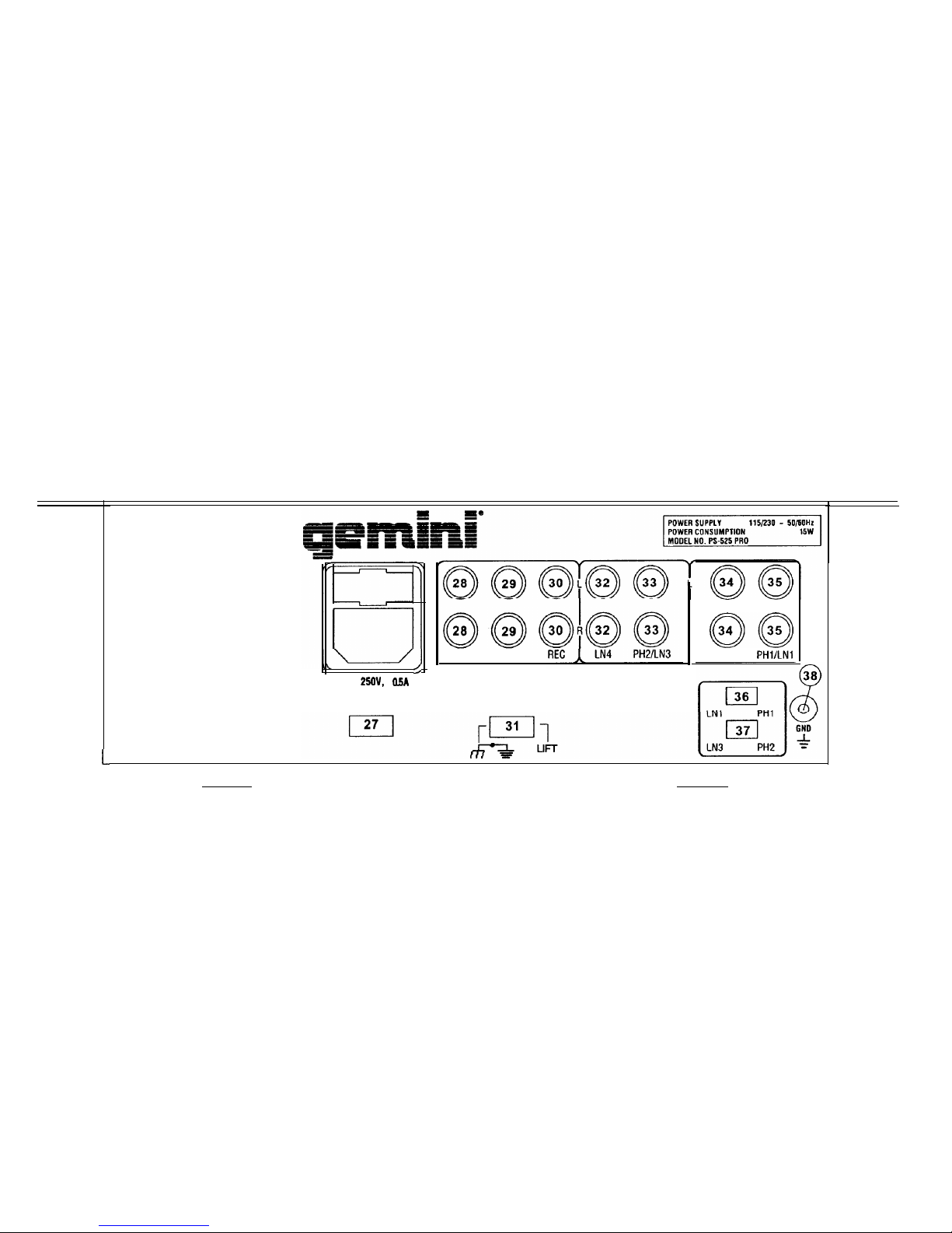
Before plugging in the power
cord,
make sure that the VOLTAGE
SELECTOR (27)
switch is
set to
the
correct voltage.
IOTE: This product is double insulated and not intended
,i be grounded.
Make
sure
that the POWER (21)
switch
is in
the
off Position.
The PS-525 PRO is supplied with 3 sets of amp output
jacks.
The
MASTER OUTPUT (28)
jacks
are
unbalanced
and used to connect to
your main amplifier. The OUTPUT REC (30)
jacks tan
be used
to
connect the mixer to
the record
input of your
recorder
enabling you
to
record
your mix. The OUTPUT BOOTH (29)
jacks allow
you to hook up
an additional amplifier.
The DJ
MIC
(1) input (found on
the
front
Panel)
accepts a 114”
connector and
balanced
and
unbalanced
microphones.
i-.On
the
rear
Panel
are 2 stereo
PHONOILINE
(33, 35) inputs and 2
stereo
LINE (32,34)
inputs. The
PHONONLINE
SWITCHES
(36,37)
enable you to set
the
(33, 35) inputs to Phono or Line. The phono
inputs
will
accept
only
turntables
with a
magnetic
cartridge. A
GROUND SCREW (38) for you to ground your
turntables is located
on
the
rear
Panel.
The stereo
line
inputs will
accept
any line
level
input
such as a CD
player,
a
cassette player,
etc.
6.
Headphones
tan
be plugged into the front
Panel mounted
HEADPHONE
(22)
jack.
Depending on your
System configuration,
sometimes applying the ground
will
create
a quieter
Signal
path. Sometimes lifting
the
ground
tan eliminate
ground loops and hum to
create
a quieter
Signal path.
1. With the mixer on, listen to
the System
in idle mode (no
Signal
present)
with
the
ground applied (the GROUND LIFT SWITCH (31) in
the left
Position).
2. Then turn the power off before moving the GROUND LIFT
SWITCH (31). Lift
the
ground by moving the GROUND LIFT SWITCH
to
the
right,
turn
the
power back on and listen to detenine
which
Position
will provide a
Signal
devoid of
background
noise and hum.
Keep the GROUND LIFT SWITCH in
the
ground
Position
if
the
noise
level
remains
the
same in either Position.
CAUTION: DO NOT TERMINATE THE AC GROUND ON THE POWER MIXER
IN ANY WAY. TERMINATION OF THE AC GROUND CAN BE HAZ4RDOUS.
POWER ON:
Once you
have made all
the
equipment connections
to
your mixer, press the POWER SWITCH (21).
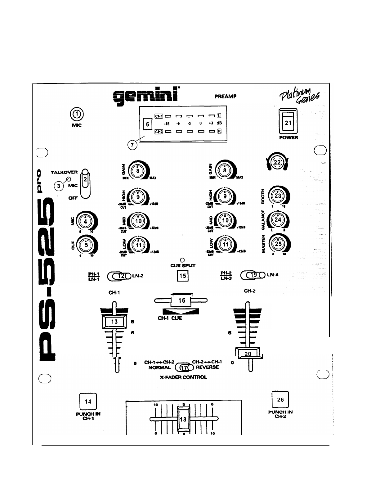
CHANNEL 1: The GAIN
(8),
HIGH
(9),
MID
(lO),
and LOW (11) controls
allow
you to
fully adjust
the selected
source. Switch #
(12)
allows you
to
select either
the
PHON0
l/LINE
1 (35) or
the LINE
2 (34) input. The
CHANNEL
SLIDE
(13) controls the output
level
of this channel.
CHANNEL 2: The GAIN
(8),
HIGH
(9),
MID
(IO),
and LOW (11) controls
allow
you to
fully adjust the
selected
Source. Switch #
(19)
allows
you
to select either the PHON0
21LINE
3 (33) or
the LINE
4 (32) input. The
CHANNEL
SLIDE
(20) controls the output
level
of
this
channel.
NOTE: There is Low, Mid and High equalization for each
channel with an extremely wide range of adjustment.
SUGGESTION:
You tan use
the Cut Features on
each channel
to
remove Low, Mid
and/or
High to
create special effects.
4.
CROSSFADER SECTION: The CROSSFADER (18) allows the mixing of
one
Source
into another. The
left
side of the CROSSFADER (18)
is
CHANNEL 1 and the right side is CHANNEL 2. The CROSSFADER
REVERSE SWITCH (17)
allows
you to reverse the crossfader so
that
CHANNEL 2 is
controlled
by the
left
side of the crossfader and
CHANNEL 1 is
controlled
by the right side of
the
crossfader.
NOTE: When the CROSSFADER REVERSE SWITCH
(17) is activated (moved to the right), only the crossfader
reverses. The Channel Slides, Punch In, Gain, and tonal
controls da not reverse.
The CROSSFADER (18) in your
unit is
removable and if
the
need
arises tan
be easily replaced. Crossfader
units
are available in three
varieties. Part # RF-45
(which
is
identical
to
the
crossfader supplied
with the mixer) has a 45 mm travel from side to side. Part # RF-30
is
available with a 30 mm
travel
distance. Also available is the PSF-45
with a
special curve
designed for scratch mixing. Just
purchase
one
of these crossfader units from your Gemini
dealer
and follow
these
instructions:
Page 3
Page 5

1.
Unscrew
the outside FADER PLATE SCREWS (B). DO
tauch the INSIDE SCREWS (C).
2. Carefully
lift
the fader and
unplug
the CABLE
(D).
3. Plug
the
new fader into the
cable
and
place
it back in
mixer.
4.
Screw
the fader to the mixer.
0
c
A
c
0
L
I
1’
i,
I
J
D-
BS!.
not
the
5.
PUNCH IN: The PUNCH IN BUTTONS
(14,26) allow
you to add a
channel’s
Signal
to the mix when the crossfader is set to the opposite
channel.
6.
OUTPUT CONTROL SECTION: The level of the
MASTER OUTPUT (28)
is
controlled
by the MASTER (25) control. The BALANCE (24) control
will
allow
the MASTER OUTPUT
Signal
to be
balanced
between the
left
and right speakers. The BOOTH (23) control adjusts the level of the
BOOTH OUTPUT (29). HINT: The booth OUTPUT is used by some
DJs
to
run
monitor speakers in their DJ booth. You
tan
also use it as a
second
ZONE or AMP output.
NOTE: The RECORD OUT (30) has no level control. The
level Is set by the channel slides and the gain controls of
the selected channel. The tonal qualities are set by the
bass, treble and mid controls of that same channel.
7. TALKOVER SECTION: The purpose of the talkover
section
is to allow
the program
playing to be muted so that
the mit tan
be heard above
the
music.
The
MIC/TALKOVER
SVVITCH (2) has three
settings.
When
the
MICTTALKOVER
SWITCH (2) is in the bottom Position, the
mit
and
talkover are both off. When the
MICITALKOVER SWITCH
(2) is in the
center Position
the
mit
is on, the
MIC
INDICATOR (3) will glow, but
talkover is off. When the
MICITALKOVER
SWITCH (2) is in the
top
Position, the
mit
and talkover will be on and the volume of all
sources
except the
Mit
input are lowered by 16
dB.
LEVEL (4) controls the
level of
the
MIC.
8.
CUE SECTION: By connecting a set of headphones to the HEADPHONE
(22)
jack,
you
tan
monitor either channel or both together. Select the
CHANNEL 1 by sliding the CUE SLIDER (16) control to the
left
or
CHANNEL 2 by sliding the CUE SLIDER (16) control to the right. Use
the
CUE LEVEL (5) control to
adjust
the headphone volume without
effecting the
Overall
mix. Use the CUE SPLIT (15) button to
Split
the
Signals
from
each
channel so that CHANNEL 1 will be heard in one
earphone and CHANNEL 2 will be heard in the other earphone.
9.
DISPLAY: The dual
function
DISPLAY (7) indicates either the MASTER
OUTPUT
(28,31)
left and right levels or the CHANNEL 1 and
CHANNEL 2 input levels. You
tan choose
the
Option
you
want
by
pressing the DISPLAY (6)
button.
NOTE: When the DISPLAY (7) is in the CHANNEL 11
CHANNEL 2 display mode, by adjusting the Individual
channel galn and tone controls, you tan increase or
decrease the slgnal to match the other channel’s Signal.
The channel slides and crossfader have no effect on the
dlsplay readlngs.
INPUTS:
DJ
Mit
...................................................
.1.5mV
2Kohm
balancec
Phono
........................................................................
.3mV
47Kohr
Line..
.....................................................................
150
mV
27Kohr
OUTPUTS:
Amp/Booth.
.....................................................
0 dB 1V 4000hr
Max..
...........................
.24V
Peak to
Pea+
Ret
........................................................................... 225mV 5Kohr
GENERAL:
Low (Channels 1 - 2) ........................................................
+ 12dB/-32 dE
Mid (Channels 1 - 2).........................................................+
12dB/-32 dE
High (Channels 1 - 2).....................................................
+ 12dBI-32 di
Gain (Channels 1 - 2)
........................................................... 0 to
-2od:
Frequency
Response
....................................
2OHz - 20KHz +/-
2dE
Distortion
................................................................................
0.02”
S/N
Ratio
...............................................................
better
than
80dt
Talkover Attenuation.
.............................................................
-16di
Headphone Impedance.........................................................
16ohn
Power Source.. ...........................................
115/23OV 50/60Hz 15\’
Dimensions..
...............
10”~
x
3S”h
x 14”d (254 x 89 x 305
mrr
Weight..
.........................................................................
.6.6
Ibs.(3kg
Page 4
Page 6

Wir gratulieren Ihnen zum Kauf eines Gemini PS-525 PRO Mischpults.
Dieses moderne Mischpult enthält die neuesten Funktionen mit dreijähriger
Garantie,
ausscheließlich
crossfader und Kanalschieber. Vor
Anwendung dieses Mischpults bitte alle Anweisungen sorgfältig
durchlesen.
CUT Funktion (Entfernungsfunktion) der
Bass-,
Mid- und
High-
Frequenzen in Kanälen 1 und 2
2 Stereokanäle
2 konvertierbare Eingänge für
PhonoleitungenILeitung,
Eingänge für 2
Leitungen, Eingang für 1 Mikrophon
Buchse für DJ Mikrophon
(1/4”)
Tief, Mittel, Hoch, Tonstarken- und Balanceregier für jeden Kanal
Punch In für jeden Kanal
Ausgänge für Master, Kabine und Aufnahme
Doppelte Tonartanzeige
Vor Anwendung dieses Geräts bitte alle Anweisungen sorgfältig
durchlesen.
Ias
Gerät nicht öffnen, um das Risiko elektrischen Schocks zu
vermeiden. Es enthält KEINE VOM ANWENDER ERSETZBAREN TEILE.
Die Wartung darf nur von
befahigten
Wartungstechnikern
durchgeführt werden.
Das Gerät von direktem Sonnenlicht oder einer Wärmequelle wie
Heizkörper oder Ofen aussetzen.
Dieses Gerät darf nur mit einem feuchten Tuch gesäubert werden.
Keine Lösungs- oder Reinigungsmittel benutzen.
Bei Umzügen sollte das Gerät in seinem ursprünglichen Versandkarton
und Verpackungsmaterial verpackt werden. Dadurch verhindert man,
daß das Gerät während des Transportes beschädigt wird.
DIESES GERÄT NICHT REGEN ODER FEUCHTIGKEIT AUSSETZEN.
AN DEN REGLERN ODER SCHALTERN KEIN SPRAY-
REINIGUNGSMITTEL ODER SCHMIERMITTEL BENUTZEN.
1. Bevor Sie das Stromkabel anschließen, darauf achten, daß der
VOLTAGE SELECTOR (27) (Spannungswähler) auf die richtige
Spannung einstellt ist.
HINWEIS: Dieses Produkt ist doppelisoliert und darf nicht
geerdet werden.
’-.Darauf achten, daß der Spannungsschalter POWER (21) in
Off-
Position geschaltet ist.
3.
Der PS-525 PRO verfügt über 3 Ausgangsbuchsenpaare. Die Buchsen
MASTER OUTPUT (28) sind unkompensiert und dienen zum Anschluß
an den Hauptverstärker. Die Buchsen OUTPUT REC (30) können dazu
dienen, das Mischpult an den Aufnahmeeingang des
Aufnahmegerätes
anzuschlieaen,
um die Tonmischung aufnehmen zu
können. Die Buchsen OUTPUT BOOTH (30) ermöglichen Anschluß an
einen zusätzlichen Verstärker.
Der Eingang DJ
MIC (1)
(an der Vorderseite) nimmt Anschlüsse mit
Durchmesser von
0,38
mm
(1/4”),
und balancierte und unbalancierte
Mikrophone auf.
An der Rückwand sind jeweils 2 Stereoeingänge
PHONOILINE
(33,
35)
2 Stereoeingänge LINE (32, 34) angebracht. Die Schalter
PHONOI
LINE (36, 37) ermöglichen Ihnen, die Eingänge (33, 35) an Phono oder
Line anzuschließen. Die Phono-Eingänge werden nur Plattenspieler mit
einem magnetischem Tonabnehmer aufnehmen. Eine Erdungschraube
GROUND (38) zur Erdung des Plattenspielers ist an der Rückwand
angebracht. Die Stereo-Leitungseingängen nehmen Geräte wie
CD-
oder Kassettenspieler auf.
Kopfhörer können an der an der Vorderwand montierten
Kopfhörer-
Buchse HEADPHONE (22) eingesteckt werden.
1.
Wenn das Mischpult eingeschaltet ist, das System im Ruhemodus
(ohne Signal) bei angelegter Masse abhorchen (der
Masse-
Trennschalter (31) ist nach links geschaltet).
2.
Dann den Leistungsschalter ausschalten bevor der
Masse-
Trennschalter (31) betätigt wird. Den Masse-Trennschalter nach
rechts legen, die Leistung wieder einschalten und horchen, um zu
bestimmen, welche Position ein Signal ohne Grundgeräusch und
Brummen erzeugt. Den Masse-Trennschalter in Masseposition halten,
falls der Geräuschpegel in beiden Position
unverandert
bleibt.
Abhängig von Ihrer Systemkonfiguration, wenn man hin und wieder
Masse anlegt, kann man damit einen ruhigeren Signalpfad schaffen.
Wenn man hin und wieder die Masse trennt, kann man dadurch
Massekreise und Brummen eliminieren, um einen ruhigeren Signalpfad
schaffen.
VORSICHT: DIE MASSE IN KEINERWEISE AM MISCHPULTABSCHLIESSEN.
DER ENDABSCHLUSS DER MASSE KANN MIT GEFAHREN VERBUNDEN
SEIN.
STROM EIN: Nachdem Sie das Gerät am Mischpult angeschlossen
haben, drücken Sie auf die Taste POWER (21).
KANAL 1: Die Regelelemente GAIN
(8),
HIGH
(9),
MID
(IO)
und LOW
(11) ermöglichen ein vollkommenes Regulieren der ausgewählten
Tonquelle. Schalter # (12) ermöglicht, den Eingang von PHON0
l/LINE
1 (35) oder LINE 2 (34) auszuwählen. CHANNEL SLIDE (13) regelt
den Ausgangstonsignal dieses Kanals.
KANAL 2: Die Regelelemente GAIN
(8),
HIGH
(9),
MID (10) und LOW
(11) ermöglichen ein vollkommenes Regulieren der
ausgewahlten
Tonquelle. Schalter # (19) ermöglicht, den Eingang von
PHON0 2/LINE
3 (33) oder LINE 4 (32) auszuwählen. CHANNEL SLIDE (20) regelt
den Ausgangstonsignal dieses Kanals.
HINWEIS: Für jeden Kanal gibt es niedrige (Low), mittlere
(Mid) und hohe (High) Entzerrung mit einem äu erst breiten
Regulierbereich, welches eine gleichförmigere Mischung
bietet.
RATSCHLAG: Sie können die CUT Funktion eine jeden Kanals
benutzen, um Low, Mid
undloder
High zu entfernen um dadurch
Spezialeffekte zu
erziehlen.
4.
ÜBERBLENDER: Der Überblender CROSSFADER (18)
ermöglichtdas
Mischen von Tonquellen. Links des CROSSFADER (18) ist KANAL 1
und die rechte ist KANAL 2. Der CROSSFADER REVERSE SWITCH
(17) ermöglicht den Rückwärtsgang des Crossfaders Kanal 2 wird
nun kontrolliert durch die linke Seite des Crossfader und Kanal 1 durch
die rechte Seite.
Page 5
Page 7

HINWEIS: Bel Aktivierung des CROSSFADER REVERSE
SWITCH (17) (nach rechts gesthieben)
geht
nur der
Crossfader rückwärts. Die Kanalschieber, Punch In, Gain
und Tonregler gehen nicht rückwärts.
Der CROSSFADER (18) Ihres Geräts kann entfernt werden und läßt
sich bei Bedarf leicht ersetzen. Überblender sind in drei Größen
verfügbar. Teile-Nr. RF-45 (die mit dem Überblender Ihres Geräts
identisch ist)
hateine Seitenverschiebbarkeit
von 45 mm. Gleichfalls ist
Teile-Nr. 30 mit einer
Verschiebbarkeit
von 30 mm verfügbar. Ebenfalls
9. ANZEIGE: Das Zweifunktionsanzeige DISPLAY (7) zeigt entweder die
linken und rechten Pegel des MASTER OUTPUT (28, 31)von KANAL
1 und KANAL 2. Sie
kt)nnen
die gewünschte Option
auswahlen, inden-
Sie DISPLAY (6) drücken.
ist Teile-Nr. PSF-45 mit einer Spezialkrümmung für
Rasp&mischen
verfügbar. Sie können einen dieser Überblender bei Ihrem
Gemini-
Händler beziehen und diese Anweisungen befolgen.
1.
Dieäußeren SCHRAUBEN DER
ÜBERBLENDERPIAITE
(B)
losschrauben. Nicht die INNENSCHRAUBEN (C)
losschrauben.
HINWEIS: Wenn DISPLAY (7) der Anzeigemodus von KANAL
PIKANAL 2 ist, können Sie, Indem Sie die individuellen
KanaLTonstärkenregelungen justieren, das Signal erhöhen
oder mindern, um es dem Signal des anderen Kanals
anzupassen. Der Kanalschieber und der Oberblender haben
keinen EinfluR auf die Anzeige.
2. Den Überblender vorsichtig anheben und das KABEL (D)
herausziehen.
3.
Den neuen Überblender in das Kabel hineinfügen und wieder
in das Mischpult setzen.
4. Den neuen Überblender mit den Schrauben am Mischpult
befestigen.
EINGÄNGE:
0
c
A
C B
DJ-Mikrophon.. .....................................
1,5 mV,
2 K-Ohm
balancec
Phono
....................................................................
3
mV,
47 K-Ohr
Leitung ..............................................................
150
mV,
27 K-Ohr:
AUSGÄNGE:
L
I
Amp/Kabine
.......................................................
0 dß 1 V 400 Ohn
max.
............................ 24 V
Spitze-SpitZ
Aufnahme..
..........................................................
.225 mV5K-Ohr
ALLGEMEINES:
D-
?&
5.
PUNCH IN: Die Taste PUNCH IN
(14,26)
ermöglicht Ihnen, ein Signal
eines Kanals dem Tongemisch hinzuzufügen, wenn der Überblender
auf den
gegenüberleigenden
Kanal eingestellt ist.
HINWEIS: RECORD OUT (30) enthält keine
Tonstärkenregelung. Die Tonstärke wlrd durch KanalSchiebevorrichtungen und die Tonstärkenregler des
ausgewählten Kanals eingestellt. Die Tonqualität wird
durch die Tiefen-, Höhen, und Mittelbereichsregler dieses
Kanals eingestellt.
Page 6
6.
AUSGANGSREGELUNG. Der Pegel des MASTER OUTPUT (28)
(Verstärkerausgang) wird mittels der Steuervorrichtung MASTER (25)
gesteuert. Die Steuervorrichtung BALANCE (24) (Ausgleich) erlaubt
einen Ausgleich des Verstärkerausgangssignals zwischen dem linken
und dem rechten Lautsprecher. Die Steuervorrichtung BOOTH (23)
(Kabine) stellt den Pegel des Kabinenausgangs BOOTH OUTPUT (29)
ein. EMPFEHLUNG: Die Kabinenausgang wird von einigen
DJs
benutzt,
um die Lautsprecher in der DJ-Kabine zu überwachen. Ebenfalls kann
es als zweiter ZONE - oder AMP-Ausgang benutzt werden.
Tiefenregler (Kanäle 1 - 2)
..............................................+12
dB/-32 dE
Mittenregler (Kanäle 1 - 2)
..............................................
+
12
dB/-32 dE
Höhenregler (Kanäle 1 - 2)..............................................
+
12
dBI-32 di
Tonstärkenregler (Kanäle 1 - 2)
.....................................
0 bis -20
dF
Frequenzgang
............................................
20 Hz - 20 KHz
+/-
2
dF
Klirrfaktor
...............................................................................
0,029
Störabstand
........................................................... besser als 80
dF
Talkover-Dämpfung.. ............................................................. -16
d:
Kopfhörerimpedanz..
..........................................................
.16
Ohr
Stromversorgung..
.................................
.l lW230
V, 50160 Hz,
15 V
Abmessungen
.......................................... 254 x 89 x 305 mr
Gewicht................................................................................
3k
7. TALKOVER: Durch die Talkover-Funktion wird das abgespielte
Programm gedämpft, um eine Ansage über das Mikrophon hören zu
können. Der Schalter
MWTALKOVER
(2) hat drei Einstellungen.
Wenn der Schalter
MICITALKOVER
(2) in der unteren Position steht,
sind MIC und Talkover beide ausgeschaltet. Steht der Schalter
MICH
TALKOVER (2) in der mittleren Position, ist MIC eingeschaltet. Der
MIC-Anzeiger (3) ist erleuchtet, jedoch ist Talkover ausgeschaltet.
Wenn der Schalter
MICITALKOVER
(2) in der oberen Position steht,
sind
MIC
und Talkover eingeschaltet, und Lautstärken aller Tonquellen,
außer des MIC-Eingangs, werden um 16 dB reduziert. LEVEL (4)
reguliert die Tonstärke von MIC.
8.
CUE: Indem Sie die Kopfhörer an der Buchse KOPFHÖRER (22)
anschließen, können Sie einen oder alle Kanäle überwachen. Wählen
die KANAL 1 aus, indem Sie den Regler CUE SLIDER (16) nach links
schieben, oder Kanals II auswählen, indem Sie den Regler CUE SLIDER
(16) nach rechts schieben. Betätigen Sie die Taste CUE LEVEL (5) um
die Tonstärke des Kopfhörers zu regulieren ohne Einfluß auf die
Mischung. Betätigen Sie die Taste CUE SPLIT
(15),
um die Signale von
jedem Kanal zu trennen, so daß KANAL 1 in einem Teil
des
Kopfhörers
und KANAL 2 im anderen Teil gehört werden kann.
Page 8

Page 9

SOUND
I
=
=
=
TH
Z
In the U.S.A., if you have any
Problems
with this
unit,
cal1 1-800-476-8633
for customer Service. DO
not return equipment to your
dealer.
I
Parts of the design of this
product
may be protected by
woridwide Patents.
Information in this manual is
subject
to
Change
without
notice
and does not represent a commitment on the
part
of the vendor. Gemini Sound Products Corp.
shall
not be
liable
for any loss or darnage whatsoever arising
from the use of information or any
error contained
in this manual.
No part of this manual may be reproduced, stored in a retrieval
System or
transmitted, in any form or by any
means,
electronie,
electrical, mechanical, Optical, Chemical, including photocopying and recording, for any
purpose without the express
written
Permission of Gemini Sound Products Corp..
lt is recommended that all maintenance and
sen/ice
on the
product
should be
carried
out by Gemini Sound
Products Corp. or it’s authorized agents. Gemini Sound Products Corp.
cannot accept
any liability whatsoever
for any loss or darnage
caused
by
Service,
maintenance or repair by unauthorized personnel.
Worldwide Headquarters l 8 Germak Drive, Carteret, NJ 07008 l USA
Tel (732) 969-9000 l Fax (732) 969-9090
Gemini Sound Products Corp. l 2851 Evans Street, Hollywood, FL
33020.
USA
Tel (954) 920-1400 . Fax (954)
920-4105
GSL France l 11 Avenue
Leon Harmel, Z.I Antony,
92160,
Antony
l France
Tel330155590470~Fax330155590480
Gemini Sound Products Ltd. l Unit C4, Hazleton Industrial Estate, Lakesmere Road
Waterlooville
PO8
9JU
l United Kingdom
Tel
(0)1705
591771 l Fax
(0)1705
593533
Gemini Sound Products GmbH l Ottostraße 6, D-85757 Karlsfeld . Germany
Tel 49-8131-39171-0 l Fax 49-8131-39171-9
0
Gemini Sound Products Corp. 1998
All Rights
Reserved
 Loading...