

Page 1
313131
31
1
3
4
5
14
15
16
14
15
16
14
15
16
14
15
16
30
2
6
17
17
17
17
32
7
21 2318 25
33
8
9
13
10
11
12
27
19
20
22
20
28
24
20
26
20
34
35
29
Page 1
Page 2
52
Page 2
36
LIFT
37
37
38
38
49
39
39
40
40
41
41
49
42
42
43
43
44
44
45
45
50
46
46
47
48
51
Page 3

Introduction
Congratulations on purchasing the Gemini PS-1000 PRO mixer. This
state of the art mixer is backed by a three year warranty, excluding
crossfader and channel slides. Prior to use, we suggest that you
carefully read all the instructions.
Features
• 4 Stereo Channels
• State of the Art Cue Section
• 1 Phono/Line Convertible, 2 Phono, 5 Line, and 3 Mic Inputs
• Cut Feature for Low, Mid and High for each channel
• Gain, High, Mid and Low tone controls for each channel
• Talkover
• Balanced and Unbalanced Master Outputs
• Booth Output
• Master Output Peak Hold LED Meters
• Prefader Input Level Peak Hold LED Meters for each channel
Cautions
1. Always test equipment before rack mounting. Retain a copy of your
sales receipt for warranty purposes.
2. All operating instructions should be read before using this
equipment.
3. To reduce the risk of electrical shock, do not open the unit. There are
NO USER REPLACEABLE PARTS INSIDE. Please refer servicing to a
qualified service technician.
In the U.S.A., if you have any problems with this unit,
call 1-732-738-9003 for customer service. Do not return
equipment to your dealer.
4. Do not expose this unit to direct sunlight or to a heat source such as
a radiator or stove.
5. This unit should be cleaned only with a damp cloth. Avoid solvents
or other cleaning detergents.
6. When moving this equipment, it should be placed in its original carton
and packaging. This will reduce the risk of damage during transit.
7. DO NOT EXPOSE THIS UNIT TO RAIN OR MOISTURE.
8. DO NOT USE ANY SPRAY CLEANER OR LUBRICANT ON ANY
CONTROLS OR SWITCHES.
Connections
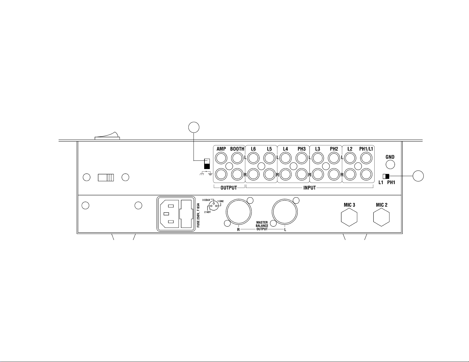
1. Before plugging in the power cord, make sure that the VOLTAGE
SELECTOR (36) switch is set to the correct voltage.
NOTE: This product is double insulated and not intended
to be grounded.
2. Make sure that the POWER (1) switch is in the off position. The
POWER LED (2) will be off.
3. The PS-1000 PRO is supplied with 2 sets of amp output jacks. The
BALANCED OUTPUT AMP (49) jacks are used to connect to your
main amplifier using standard XLR cables. We recommend using the
balanced amp outputs if the cables to your amp are 25 feet or more.
Balanced outputs have three separate conductors, two of which
are signal (positive and negative) and one shield (ground). Pin 1 is
ground (shield). Pin 2 is signal hot (positive). Pin 3 is signal cold
(negative). The OUTPUT AMP (37) jacks are unbalanced and used
to connect to your main amplifier. The OUTPUT BOOTH (38) jacks
allow you to hook up an additional amplifier.
4. The MIC 1 (3) input (found on the front panel) accepts a 1/4" or XLR
connector. The MIC 2 (51) input and the MIC 3 (50) input (found on
the rear panel) accept 1/4" connectors. All accept balanced and
unbalanced microphones.
5. On the rear panel are 1 stereo PHONO/LINE (46) input, 2 stereo
PHONO (42, 44) inputs, and 5 stereo LINE (39, 40, 41, 43, 45)
inputs. The PHONO/LINE SWITCH (48) enables you to set the (46)
input to Phono or Line. The phono inputs will accept only turntables
with a magnetic cartridge. A GROUND SCREW (47) for you to
ground your turntables is located on the rear panel. The stereo line
inputs will accept any line level input such as a CD player, a cassette
player, etc.
6. Headphones can be plugged into the front panel mounted
HEADPHONE (13) jack.
Using the Ground Lift Switch
Depending on your system configuration, sometimes applying the
ground will create a quieter signal path. Sometimes lifting the ground
can eliminate ground loops and hum to create a quieter signal path.
1. With the mixer on, listen to the system in idle mode (no signal
present) with the ground applied (the GROUND LIFT SWITCH (52) in
the bottom position).
2. Then turn the power off before moving the GROUND LIFT
SWITCH (52). Lift the ground by moving the GROUND LIFT SWITCH
to the top position, turn the power back on and listen to determine
which position will provide a signal devoid of background noise and
hum. Keep the GROUND LIFT SWITCH in the ground position if the
noise level remains the same in either position.
CAUTION: DO NOT TERMINATE THE AC GROUND ON THE POWER MIXER
IN ANY WA Y. TERMINA TION OF THE AC GROUND CAN BE
HAZARDOUS.
Operation
1. POWER ON: Once you have made all the equipment connections to
your mixer, press the POWER SWITCH (1). The power will turn on
and the POWER LED (2) will glow.
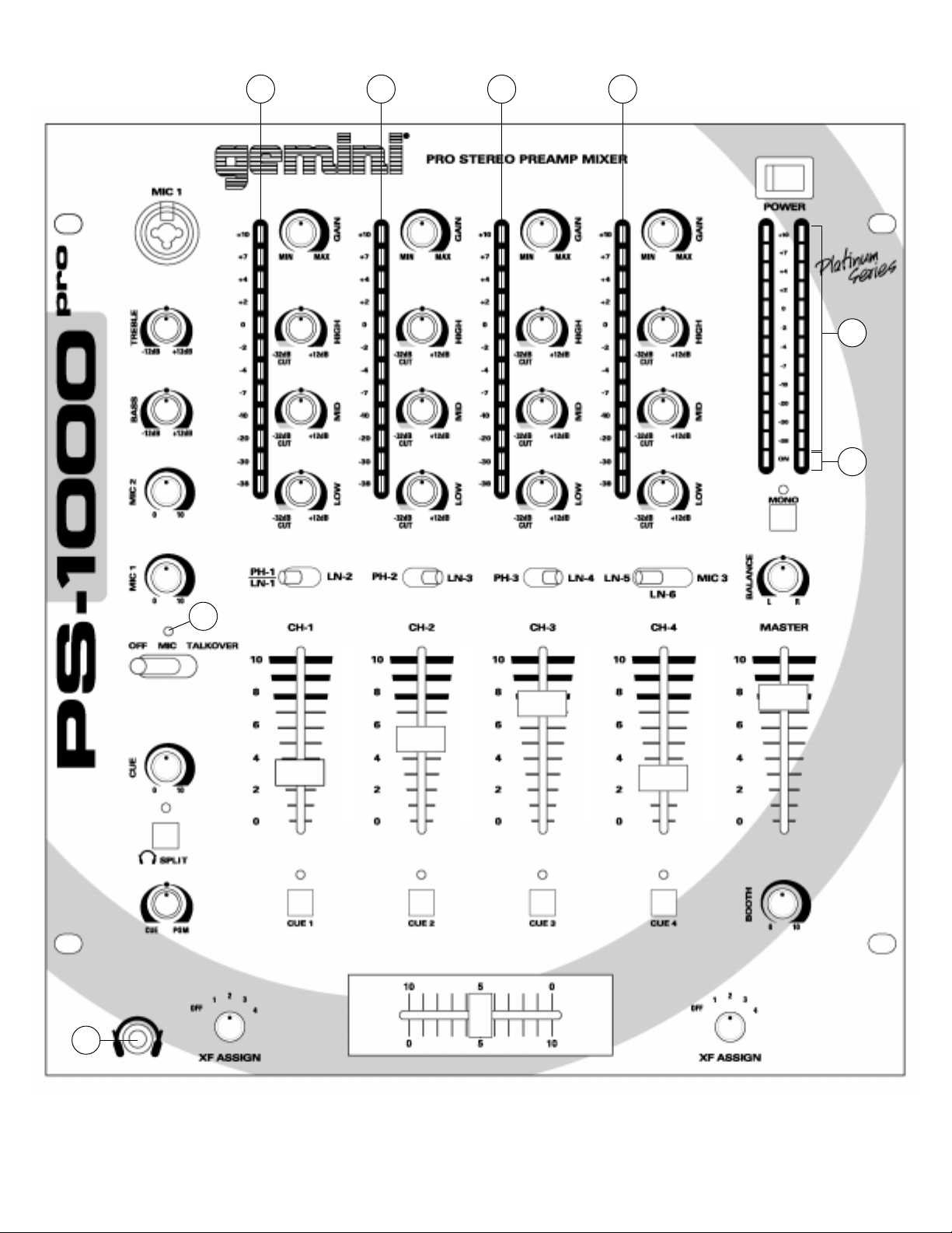
2. CHANNEL 1: The GAIN (14), HIGH (15), MID (16), and LOW (17)
controls allow you to fully adjust the selected source. Switch # (18)
allows you to select the PHONO 1/LINE 1 (46) or the LINE 2 (45)
input. The CHANNEL SLIDE (19) controls the input level of this
channel.
3. CHANNEL 2: The GAIN (14), HIGH (15), MID (16), and LOW (17)
controls allow you to fully adjust the selected source. Switch # (21)
allows you to select the PHONO 2 (44) or the LINE 3 (43) input. The
CHANNEL SLIDE (22) controls the input level of this channel.
4. CHANNEL 3: The GAIN (14), HIGH (15), MID (16), and LOW (17)
controls allow you to fully adjust the selected source. Switch # (23)
allows you to select the PHONO 3 (42) or the LINE 4 (41) input. The
CHANNEL SLIDE (24) controls the input level of this channel.
5. CHANNEL 4: The GAIN (14), HIGH (15), MID (16), and LOW (17)
controls allow you to fully adjust the selected source. Switch # (25)
allows you to select the LINE 5 (40), LINE 6 (39) or the MIC 3 (50)
input. The CHANNEL SLIDE (26) controls the input level of this
channel.
NOTE: There is Low, Mid and High equalization for each
channel with an extremely wide range of adjustment
providing a smoother mix.
Page 3
Page 4
SUGGESTION: You can use the Cut Features on each channel to
remove Low, Mid and/or High to create special effects.
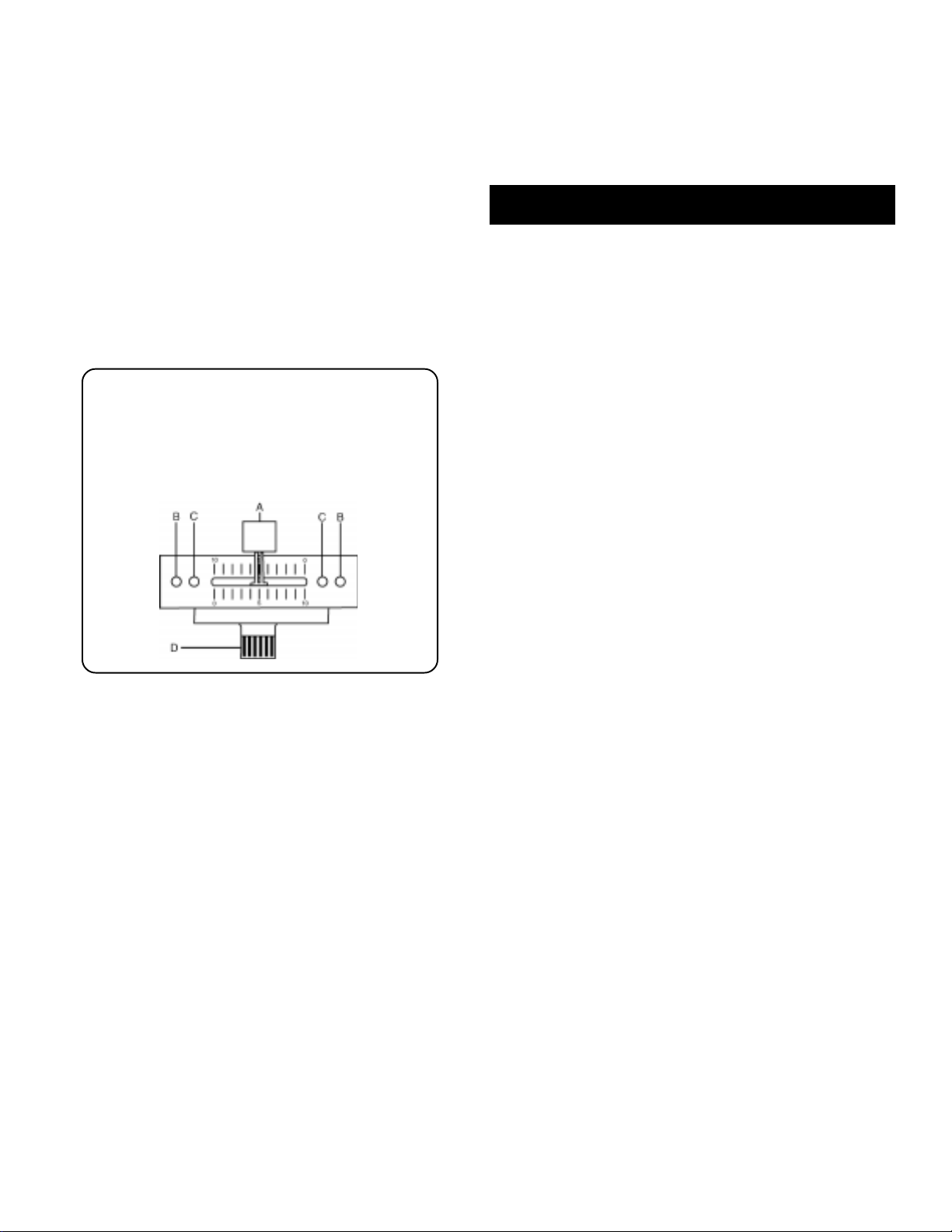
6. CROSSFADER SECTION: The CROSSFADER (28) allows the mixing
of one source into another. The PS-1000 PRO features an
assignable crossfader. The ASSIGN (27, 29) switches allow you to
select which channel will play through each side of the crossfader.
The ASSIGN (27) switch has 5 settings (OFF, 1, 2, 3 or 4) and
allows you to select channel 1, 2, 3 or 4 to play through the left side
of the crossfader. The ASSIGN (29) switch has 5 settings (OFF, 1,
2, 3 or 4) and allows you to select channel 1, 2, 3 or 4 to play
through the right side of the crossfader. With the ASSIGN switch in
the off position, that side of the crossfader will be inactive. The
CROSSFADER (28) in your unit is removable and if the need arises
can be easily replaced. Crossfader units are available in three
varieties. Part # RF-45 (which is identical to the crossfader supplied
with the mixer) has a 45 mm travel from side to side. Part # RF-30 is
available with a 30 mm travel distance. Also available is the PSF-45
with a special curve designed for scratch mixing. Just purchase one
of these crossfader units from your Gemini dealer and follow these
instructions:
1. Unscrew the outside FADER PLA TE SCREWS (B). Do not
touch the INSIDE SCREWS (C).
2. Carefully lift the fader and unplug the CABLE (D).
3. Plug the new fader into the cable and place it back in the
mixer.
4. Screw the fader to the mixer.
7. OUTPUT CONTROL SECTION: The level of the AMP OUT (37, 49) is
controlled by the MASTER (34) slide and the BALANCE CONTROL
(33). The BOOTH (35) control adjusts the level of the BOOTH
OUTPUT (38). HINT: The booth OUTPUT is used by some DJs to run
monitor speakers in their DJ booth. You can also use it as a second
ZONE or AMP output. Activating the MONO (32) button (the mono
LED will light) makes the master output mono.
8. TALKOVER SECTION: The purpose of the talkover section is to allow
the program playing to be muted so that the mic can be heard above
the music. The MIC/TALKOVER SWITCH (9) controls MIC 1 and MIC
2 and has three settings. When the MIC/TALKOVER SWITCH (9) is
in the left position, MIC 1 and MIC 2 and talkover are off. When the
MIC/TALKOVER SWITCH (9) is in the center position MIC 1 and MIC
2 are on, the MIC INDICATOR (8) will glow, but talkover is off.
When the MIC/TALKOVER SWITCH (9) is in the right position, MIC 1
and MIC 2 and talkover will be on and the volume of all sources
except the Mic inputs are lowered by 16 dB. The TREBLE (4) and
BASS (5) controls allow you to fully adjust the tone of MIC 1 and MIC
2. MIC 1 LEVEL (7) controls the level of MIC 1. The MIC 2 LEVEL
(6) controls the level of MIC 2.
9. CUE SECTION: By connecting a set of headphones to the
HEADPHONE (13) jack, you can monitor any or all of the channels.
Press the CUE ASSIGN (20) buttons for channels 1 - 4 to select the
channel or channels to be monitored and their respective LED
indicators will glow. Use the CUE LEVEL (10) control to adjust the
cue volume without effecting the overall mix. By rotating the CUE
PGM PAN (12) control to the left you will be able to monitor the
assigned cue signal. Rotating to the right will monitor the PGM
(program) output. Use the CUE SPLIT (11) button to split the signals
from cue and program so that cue will be heard in one earphone and
program will be heard in the other earphone.
10 .DISPLAYS: The PEAK HOLD LED METER (30) indicates the
MASTER OUTPUT (37, 49) left and right channel levels. The
individual channels each have their own PREFADER INPUT LEVEL
PEAK HOLD LED METERS (31) which reflect the GAIN (14), HIGH
(15), MID (16), and LOW (17) rotary control adjustments. The
CHANNNEL SLIDES (19, 22, 24, 26) will not effect the PREFADER
INPUT LEVEL PEAK HOLD LED METERS (31).
Specifications
INPUTS:
Phono.....................................................................................3mV 47Kohm
Line...................................................................................150 mV 27Kohm
Aux...................................................................................150 mV 27Kohm
OUTPUTS:
Amp/Booth..................................................................0 dB 1V 400ohm
Max..............................20V Peak to Peak
Rec.......................................................................................225mV 5Kohm
MIC 1 & MIC 2:
DJ Mic................................................................1.5mV 2Kohm balanced
Bass..................................................................................................± 12dB
High...................................................................................................± 12dB
MIC 3:
DJ Mic................................................................1.5mV 2Kohm balanced
Controls.......................................................................................Channel 4
GENERAL:
Bass (Chnls 1-4)...................................................................+ 12dB/- 32 dB
Mid (Chnls 1-4)......................................................................+ 12dB/- 32 dB
Treble (Chnls 1-4).................................................................+ 12dB/- 32 dB
Gain (Chnls 1-4)..........................................................................0 to -20dB
Frequency Response................................................20Hz - 20KHz +/- 2dB
Distortion............................................................................................0.02%
S/N Ratio...........................................................................better than 80dB
Talkover Attenuation..........................................................................-16dB
Headphone Impedance.....................................................................16ohm
Power Source.........................................................115/230V 50/60Hz 10W
Dimensions.......................................................12.5”w x 3”h x 14”d
Weight....................................................................................10 lbs
Page 4
Page 5

Einleitung
Wir gratulieren Ihnen zum Kauf eines Gemini PS-1000 PRO Mischpults.
Dieses moderne Mischpult enthält dreijährige Garantie, ausscheließlich
crossfader und Kanalschieber. Vor Anwendung dieses Mischpults bitte
alle Anweisungen sorgfältig durchlesen.
Funktionen
• 4 Stereokanäle
• Hochentwickelter Cue Funktion
• 1 Phonoleitungen/Leitung erweiterbar, 2 Phonoleitungen, Eingänge
für 5 Leitungen und 3 Mikrophone
• CUT Funktion (Entfernungsfunktion) der Low-, Mid- und HighFrequenzen in Kanälen 1 - 4
• Talkover
• Kompensierte und unkompensierte Master-Ausgänge
• Ausgänge für Kabine
• LED-Anzeige für Master-Ausgangsspitzenwertspeicherung
• Vorregler-Eingangsspitzenwertspeicherungs-LEDs für jeden Kanal
Ausgänge haben drei (3) verschiedene Leiter: zwei für Signal (positiv
und negativ) und ein für Schutz (Grund). Zu Pin 1 (Stift 1) gehört Grund
(Schutz). Zu Pin 2 (Stift 2) gehört das aktive Signal (positiv). Zu Pin 3
(Stift 3) gehört das inaktive Signal (negativ). Die Buchsen OUTPUT
AMP (37) sind unkompensiert und dienen zum Anschluß an den
Hauptverstärker. Die Buchsen OUTPUT BOOTH (38) ermöglichen
Anschluß an einen zusätzlichen Verstärker.
4. Der Eingang DJ MIC-1 (3) (an der Vorderseite) hat einen
Durchmesser von 0,38 mm (1/4"). Der Eingang DJ MIC-2 (51) und
der Eingang DJ MIC-3 (50) (an der Rückwand angebracht) nehmen
nur Anschlüsse mit Durchmesser von 0,38 mm auf. Alle nehmen
balanzierte und unbalanzierte Mikrophone auf.
5. An der Rückwand sind jeweils 1 Stereoeingänge PHONO/LINE (46),
2 Stereoeingänge PHONO (42, 44), 5 Stereoeingänge LINE (39, 40,
41, 43, 45). Der Schalter PHONO/LINE (48) ermöglicht Ihnen, die
Eingänge (46) an Phono oder Line anzuschließen. Die PhonoEingänge werden nur Plattenspieler mit einem magnetischem
Tonabnehmer aufnehmen. Eine Erdungschraube GROUND (47) zur
Erdung des Plattenspielers ist an der Rückwand angebracht. Die
Stereo-Leitungseingängen nehmen Geräte wie CD- oder
Kassettenspieler auf.
6. Kopfhörer können an der an der Vorderwand montierten KopfhörerBuchse HEADPHONE (13) eingesteckt werden.
Benutzung des Masse-Trennschalters
Vorsichtsmaßnahmen
1. Das Gerät immer vor der Gestellmontage testen. Für
Garantiezwecke eine Kopie der Quittung aufbewahren.
2. Vor Anwendung dieses Geräts bitte alle Anweisungen sorgfältig
durchlesen.
3. Das Gerät nicht öffnen, um das Risiko elektrischen Schocks zu
vermeiden. Es enthält KEINE VOM ANWENDER ERSETZBAREN TEILE.
Die Wartung darf nur von befähigten Wartungstechnikern
durchgeführt werden.
4. Das Gerät von direktem Sonnenlicht oder einer Wärmequelle wie
Heizkörper oder Ofen aussetzen.
5. Dieses Gerät darf nur mit einem feuchten Tuch gesäubert werden.
Keine Lösungs- oder Reinigungsmittel benutzen.
6. Bei Umzügen sollte das Gerät in seinem ursprünglichen
Versandkarton und Verpackungsmaterial verpackt werden. Dadurch
verhindert man, daß das Gerät während des Transportes
beschädigt wird.
7. DIESES GERÄT NICHT REGEN ODER FEUCHTIGKEIT AUSSETZEN.
8. AN DEN REGLERN ODER SCHALTERN KEIN SPRA YREINIGUNGSMITTEL ODER SCHMIERMITTEL BENUTZEN.
Anschlüsse
1. Bevor Sie das Stromkabel anschließen, darauf achten, daß der
VOLTAGE SELECTOR (36) (Spannungswähler) auf die richtige
Spannung einstellt ist.
HINWEIS: Dieses Produkt ist doppelisoliert und darf nicht
geerdet werden.
2. Darauf achten, daß der Spannungsschalter POWER (1) in OffPosition geschaltet ist. Die POWER LED (2) wird ausgeschaltet sein.
3. Der PS-1000 PRO verfügt über 2 Ausgangsbuchsenpaare. Die Buchsen
BALANCED OUTPUT AMP (49) dienen zum Anschluß an den
Hauptverstärker, wofür Standard-XLR-Kabel benutzt werden. Wir
empfehlen, kompensierte Ampereausgänge zu benutzen, wenn die
Kabel zu Ihren Ampereausgänge 8 m oder länger sind. Balanzierte
Abhängig von Ihrer Systemkonfiguration, wenn man hin und wieder
Masse anlegt, kann man damit einen ruhigeren Signalpfad schaffen.
Wenn man hin und wieder die Masse trennt, kann man dadurch
Massekreise und Brummen eliminieren, um einen ruhigeren Signalpfad
schaffen.
1. Wenn das Mischpult eingeschaltet ist, das System im Ruhemodus
(ohne Signal) bei angelegter Masse abhorchen (der Masse-
Trennschalter - GROUND LIFT SWITCH (52) ist nach unten
geschaltet).
2. Dann den Leistungsschalter ausschalten bevor der Masse-
Trennschalter - GROUND LIFT SWITCH (52) betätigt wird. Den
Masse-Trennschalter nach oben legen, die Leistung wieder
einschalten und horchen, um zu bestimmen, welche Position ein
Signal ohne Grundgeräusch und Brummen erzeugt. Den MasseTrennschalter in Masseposition halten, falls der Geräuschpegel in
beiden Position unverändert bleibt.
VORSICHT : DIE MASSE IN KEINER WEISE AM MISCHPUL T
ABSCHLIESSEN. DER ENDABSCHLUSS DER MASSE KANN MIT
GEFAHREN VERBUNDEN SEIN.
Bedienung
1. STROM EIN: Nachdem Sie das Gerät am Mischpult angeschlossen
haben, drücken Sie auf die Taste POWER (1). Der Strom wird
eingeschaltet und die POWER LED (2) erleuchtet.
2. KANAL 1: Die Regelelemente GAIN (14), HIGH (15), MID (16) und
LOW (17) ermöglichen ein vollkommenes Regulieren der
ausgewählten Tonquelle. Schalter # (18) ermöglicht, den Eingang
von PHONO 1/LINE 1 (46) oder LINE 2 (45) auszuwählen.
CHANNEL SLIDE (19) regelt den Ausgangstonsignal dieses Kanals.
3. KANAL 2: Die Regelelemente GAIN (14), HIGH (15), MID (16) und
LOW (17) ermöglichen ein vollkommenes Regulieren der
ausgewählten Tonquelle. Schalter # (21) ermöglicht, den Eingang
von PHONO 2 (44) oder LINE 3 (43) auszuwählen. CHANNEL SLIDE
(22) regelt den Ausgangstonsignal dieses Kanals.
4. KANAL 3: Die Regelelemente GAIN (14), HIGH (15), MID (16) und
LOW (17) ermöglichen ein vollkommenes Regulieren der
ausgewählten Tonquelle. Schalter # (23) ermöglicht, den Eingang
von PHONO 3 (42) oder LINE 4 (41) auszuwählen. CHANNEL SLIDE
(24) regelt den Ausgangstonsignal dieses Kanals.
Page 5
Page 6
5. KANAL 4: Die Regelelemente GAIN (14), HIGH (15), MID (16) und
LOW (17) ermöglichen ein vollkommenes Regulieren der
ausgewählten Tonquelle. Schalter # (25) ermöglicht, den Eingang
von LINE 5 (40), LINE 6 (39) oder MIC 3 (50) auszuwählen.
CHANNEL SLIDE (26) regelt den Ausgangstonsignal dieses Kanals.
HINWEIS: Für jeden Kanal gibt es niedrige (Low),
mittlere (Mid) und hohe (High) Entzerrung mit einem äu
erst breiten Regulierbereich, welches eine
gleichförmigere Mischung bietet.
RATSCHLAG: Sie können die CUT Funktion eine jeden Kanals
benutzen, um Low, Mid und/oder High zu entfernen um dadurch
Spezialeffekte zu erziehlen.
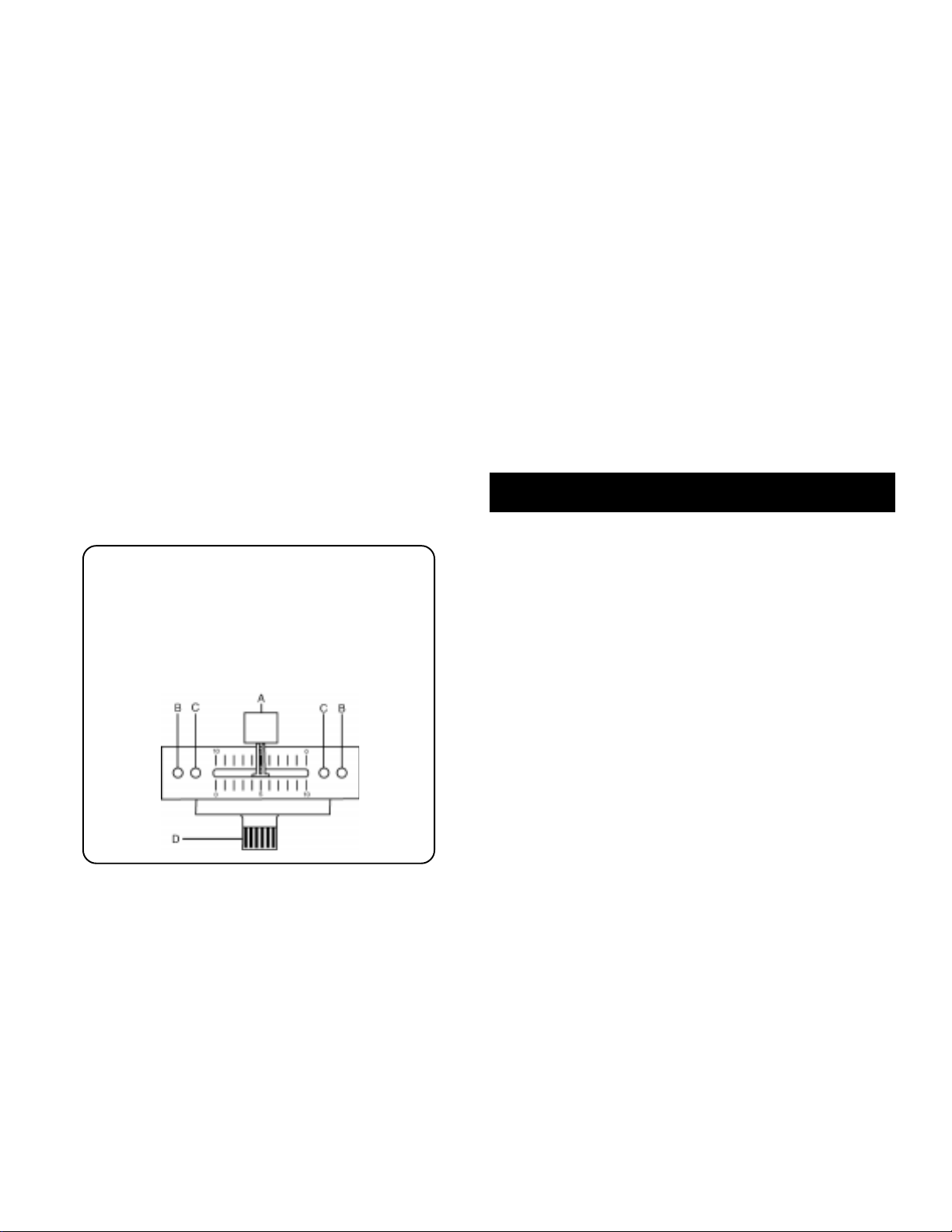
6. ÜBERBLENDER: Der Überblender CROSSFADER (28) ermöglicht das
Mischen von Tonquellen. Der PS-1000 PRO bietet einen zuweisbaren
Überblender. Die ASSIGN-Schalter (27, 29) ermöglichen Ihnen
denjenigen Kanal auszuwählen, der durch jede Seite des
Überblenders spielen wird. Der ASSIGN-Schalter (27) hat 5
Einstellungen (OFF, 1, 2, 3 oder 4) und ermöglicht Ihnen, Kanäle 1, 2,
3 oder 4 durch die linke Seite des Überblenders zu spielen. Der
ASSIGN-Schalter (29) hat 5 Einstellungen (OFF, 1, 2, 3 oder 4) und
ermöglicht Ihnen, Kanäle 1, 2, 3 oder 4 durch die rechte Seite des
Überblenders zu spielen. Wenn der ASSIGN-Schalter in OFF-Position
steht, ist diese Seite des Überblenders unwirksam. Der
CROSSFADER (28) Ihres Geräts kann entfernt werden und läßt sich
bei Bedarf leicht ersetzen. Überblender sind in drei Größen
verfügbar. Teile-Nr. RF-45 (die mit dem Überblender Ihres Geräts
identisch ist) hat eine Seitenverschiebbarkeit von 45 mm. Gleichfalls
ist Teile-Nr. 30 mit einer Verschiebbarkeit von 30 mm verfügbar.
Ebenfalls ist T eile-Nr. PSF-45 mit einer Spezialkrümmung für
Raspelmischen verfügbar. Sie können einen dieser Überblender bei
Ihrem Gemini-Händler beziehen und diese Anweisungen befolgen.
1. Die äußeren SCHRAUBEN DER ÜBERBLENDERPLATTE
(B) losschrauben. Nicht die INNENSCHRAUBEN (C)
losschrauben.
2. Den Überblender vorsichtig anheben und das KABEL (D)
herausziehen.
3. Den neuen Überblender in das Kabel hineinfügen und
wieder in das Mischpult setzen.
4. Den neuen Überblender mit den Schrauben am Mischpult
befestigen.
7. AUSGANGSREGELUNG: Der Verstärkerausgangspegel AMP OUT
(37, 49) wird vom Schieberegler MASTER (34) und BALANCE (33)
geregelt. Der Regler BOOTH (35) justiert den Pegel des BOOTH
OUTPUT (38). EMPFEHLUNG: Die Kabinenausgang wird von einigen
DJs benutzt, um die Lautsprecher in der DJ-Kabine zu überwachen.
Ebenfalls kann es als zweiter ZONE - oder AMP-Ausgang benutzt
werden. Beim Aktivieren der Taste MONO (32) (die MONO-LED
erleuchtet) ist der Ausgang Mono.
8. TALKOVER: Durch die Talkover-Funktion wird das abgespielte
Programm gedämpft, um eine Ansage über das Mikrophon hören zu
können. Der Schalter MIC/TALKOVER (9) kontrolliert MIC 1 und MIC
2, und hat drei Einstellungen. Wenn der Schalter MIC/TALKOVER (9)
in der linken Position steht, sind MIC 1/MIC 2 und T alkover beide
ausgeschaltet. Steht der Schalter MIC/TALKOVER (9) in der
mittleren Position, ist MIC 1/MIC2 eingeschaltet. Der MIC-ANZEIGER
(8) ist erleuchtet, jedoch ist Talkover ausgeschaltet. Wenn der
Schalter MIC/TALKOVER (9) in der rechten Position steht, sind MIC
1/MIC2 und Talkover eingeschaltet, und Lautstärken aller Tonquellen,
außer des MIC-Eingangs, werden um 16 dB reduziert. Die Regler
TREBLE (4) und BASS (5) ermöglichen Ihnen, den Ton von MIC 1 und
MIC 2 zu regulieren. MIC 1 LEVEL (7) reguliert die Tonstärke von MIC
1. MIC 2 LEVEL (6) reguliert die Tonstärke von MIC 2.
9. CUE: Indem Sie die Kopfhörer an der Buchse KOPFHÖRER (13)
anschließen, können Sie einen oder alle Kanäle kontrollieren.
Drücken Sie die Tasten CUE ASSIGN (20) für Kanäle 1-4, um den/die
zu kontrollierende/n Kanal/Kanäle auswählen, und deren jeweilige
LED-Anzeigen werden aufleuchten. Betätigen Sie den Regler
CUEING LEVEL (10), um die Mithörlautstärke einzustellen, ohne
dabei die allgemeine Mischung zu beeinträchtigen. Indem Sie den
Regler CUE PGM PAN (12) nach links drehen, können Sie das
zugewiesene Mithörsignal kontrollieren. Nach rechts drehen wird die
PGM- (Programm-) Ausgabe kontrolliert. Benutzen Sie die Taste CUE
SPLIT (11), um die vom Cue und Programm herleitenden Signale zu
teilen, so daß man Cue im einen Kopfhörerteil und Programm im
anderen hören kann.
10 .ANZEIGEN: Die Spitzenwertanzeige PEAK HOLD METER (3) zeigt
die linken und rechten Kanalpegel des MASTER OUTPUT (37,
49) an. Die individuellen Kanäle haben jeweils ihre eigenen
Vorregler-Eingangsspitzenwertspeicherungs-LEDs (31), die die
Drehknopfeinstellungen GAIN (14), HIGH (15), MID (16) und LOW
(17) anzeigen. Die Kanalschieberegler (19, 22, 24, 26) werden nicht
die Vorregler-Eingangsspitzenwertspeicherungs-LEDs (31)
beeinträchtigen.
Spezifikationen
EINGÄNGE:
Phono....................................................................3 mV, 47 K-Ohm
Leitung..............................................................150 mV, 27 K-Ohm
Aux...................................................................150 mV, 27 K-Ohm
AUSGÄNGE:
Amp/Kabine.......................................................0 dB 1 V 400 Ohm
max.............................20 V Spitze-Spitze
Aufnahme.............................................................225 mV 5 K-Ohm
MIKROFONE 1 & 2:
DJ-Mikrophon....................................1,5 mV, 2 K-Ohm balanzierte
Tiefe....................................................................................± 12 dB
Hoch....................................................................................± 12 dB
MIKROFONE 3:
DJ-Mikrophon....................................1,5 mV, 2 K-Ohm balanzierte
Regler.........................................................................Kanal 4
ALLGEMEINES:
Tiefenregler (Kanäle 1 - 4)........................................+ 12 dB/- 32 dB
Mittenregler (Kanäle 1 - 4)......................................+ 12 dB/- 32 dB
Höhenregler (Kanäle 1 - 4)......................................+ 12 dB/- 32 dB
Tonstärkenregler (Kanäle 1 - 4)....................................0 bis -20 dB
Frequenzgang..........................................20 Hz - 200 KHz +/- 2 dB
Klirrfaktor...............................................................................0,02%
Störabstand...........................................................besser als 80 dB
Talkover-Dämpfung...............................................................-16 dB
Kopfhörerimpedanz.............................................................16 Ohm
Stromversorgung....................................115/230 V, 50/60 Hz, 15 V
Abmessungen..........................................320 x 81 x 355 mm
Gewicht.............................................................................4.5 kg
Page 6
Page 7

Introducción
Felicitaciones por su compra del mezclador PS-1000 PRO de Gemini.
Este mezclador de la más avanzada tecnología está respaldado por una
garantía de tres años, salvo el crossfader y los mandos corredizos de
canal. Antes de usarlo, le recomendamos leer cuidadosamente todas
las instrucciones.
Características
• 4 canales estereo fonicos
• Sección Cue muy moderna
• 1 entrada fono/línea convertible, 2 entradas de fono, 5 entradas de
línea y 3 entradas para micrófono
• Característica CUT (Supresión) para Bajas, Medianas y Altas
Frecuencias para los canales 1 - 4
• Mandos de Ganancia, Bajas, Medianas y Altas para los canales 1 - 4
• Talkover
• Salidas maestras equilibradas y no equilibradas
• Salida de cabina
• Medidores DEL de Master Output Peak Hold
• Medidores DEL de Prefader Input Level Peak Hold para cada canal
Precauciones
1. Siempre haga un ensayo del equipo antes de instalarlo en su estante.
Retenga un copia de su recibo de venta para propósito de garantía.
2. Deberán leerse todas las instrucciones de operación antes de usar
el equipo.
3. Para reducir el riesgo de shock eléctrico, no abra esta unidad. No
contiene PIEZAS REEMPLAZABLES POR EL USUARIO. Por favor,
refiera el servicio a un técnico de servicio calificado.
4. No exponga la unidad a la luz solar directa ni a una fuente de calor,
por ejemplo, un radiador o estufa.
5. Esta unidad sólo deberá limpiarse con un paño húmedo. Evite el uso
de disolventes u otros detergentes de limpieza.
6. Para mover este equipo, colóquelo en la caja y empaque original, a
fin de reducir el riesgo de daños durante el transporte.
7. NO DEJE ESTA UNIDAD EXPUEST A A LLUVIA O HUMEDAD.
8. NO USE LIMPIADORES DE ROCÍO O LUBRICANTES EN
CUALESQUIER CONTROLES O INTERRUPTORES.
salida) no son equilibrados y se usan para la conexión al
amplificador principal. Los jacks OUTPUT BOOTH (38) (cabina de
salida) le permiten conectar otro amplificador.
4. La entrada DJ MIC 1 (3) (que se encuentra en el panel delantero)
acepta conector de 1/4 de pulgada o XLR. La entrada DJ MIC 2 (51)
y la entrada DJ MIC 3 (50) (que se encuentra en el panel trasero)
aceptan conector de 1/4 de pulgada. Todas aceptan micrófonos
equilibrados y no equilibrados.
5. En el panel trasero hay 1 entrada estereofónica PHONO/LINE (46), 2
entradas estereofónicas PHONO (42, 44), y 5 entradas
estereofónicas LINE (39, 40, 41, 43, 45). El conmutador PHONO/
LINE (48) le permite arreglar la entrada (46) a Phono o Line
(fonográfico o línea). Las entradas fonográficas solamente
aceptarán giradiscos con cartucha magnética. Un GROUND SCREW
(47) (tornillo de puesta a la tierra) para poner el giradiscos a tierra
se encuentra en el panel trasero. Las entradas de línea
estereofónicas aceptarán cualquier entrada de nivel de línea tal
como tocadisco de discos compactos o casetera, etc.
6. Los audífonos se enchufan en el jack de HEADPHONES (audífonos)
(13) montado en el panel delantero.
Uso del interruptor de separación de
tierra (Ground Lift)
Según la configuración de su sistema, a veces el hecho de aplicar la
tierra/masa resultará en una vía de señal con menos ruido. A veces, el
hecho de separar la tierra puede eliminar bucles de tierra y zumbido
para crear una vía de señal con menos ruido.
1. Con el mezclador prendido, escuche el sistema en modo de reposo
(sin presencia de señal) con tierra aplicada (GROUND LIFT SWITCH
(52) en la posición inferior).
2. Apague el aparato antes de desplazar el GROUND LIFT
SWITCH (52). Separe la tierra del marco moviendo el GROUND LIFT
SWITCH arriba, prenda el aparato de nuevo y escuche para
determinar cual de las posiciones le dará señal sin ruido de fondo y
sin zumbido. Mantenga el GROUND LIFT SWITCH en la posición de
puesta a tierra si el nivel del ruido permanece igual.
CUIDADO: NO TERMINE DE NINGUNA MANERA LA TIERRA C.A. EN EL
MEZCLADOR. EL HECHO DE TERMINAR LA TIERRA C.A. PUEDE SER
PELIGROSO.
Funcionamiento
Conexiones
1. Antes de conectar el cable de potencia, cerciórese de que el
SELECTOR DE VOL T AJE (36) (VOL T AGE SELECTOR) esté
posicionado en la tensión correcta.
NOTA: Este producto tiene doble aislamiento y no hace
falta ponerlo a tierra.
2. Cerciórese de que el interruptor de ENERGÍA (1) (POWER) esté en la
posición off (apagada). El DEL de ENERGÍA (2) (POWER LED)
estará apagado.
3. El aparato PS-1000 PRO está dotado de 2 series de jacks de salida
para amplificador. Los jacks BALANCED OUTPUT AMP (49)
(amplificador de salida equilibrada) se usan para la conexión al
amplificador principal con la ayuda de cables XLR estándares.
Recomendamos el uso de salidas de amplificador equilibradas si los
cables que se conectan al amplificador miden por lo menos 8 metros.
A las salidas equilibradas corresponden tres (3) conductores
distintos: dos para la función señal (positiva y negativa) y uno para
la protección (tierra). Pin 1 (espiga 1) corresponde a la tierra
(protección). Pin 2 (espiga 2) corresponde a la función de señal
activa (positiva). Pin 3 (espiga 3) corresponde a la función de señal
inactiva (negativa). Los jacks OUTPUT AMP (37) (amplificador de
1. ENCENDIDO: Una vez que haya efectuado todas las conexiones de
los equipos a su mezclador, oprima el INTERRUPT OR DE ENERGÍA -
POWER SWITCH (1). Se encenderá la unidad así como el DEL de
ENERGÍA - POWER LED (2).
2. CANAL 1: Los mandos de GAIN (14) (ganancia), HIGH (15) (alto),
MID (16) (mediano) y LOW (17) (bajo) le permiten arreglar
plenamente la fuente seleccionada. El interruptor # (18) le permite
seleccionar la entrada PHONO 1/LINE 1 (46) o LINE 2 (45). El
CHANNEL SLIDE (19) (cursor corredizo de canal) controla el
volumen de salida de este canal.
3. CANAL 2: Los mandos de GAIN (14) (ganancia), HIGH (15) (alto),
MID (16) (mediano) y LOW (17) (bajo) le permiten arreglar
plenamente la fuente seleccionada. El interruptor # (21) le permite
seleccionar la entrada PHONO 2 (44) o LINE 3 (43). El CHANNEL
SLIDE (22) (cursor corredizo de canal) controla el volumen de salida
de este canal.
4. CANAL 3: Los mandos de GAIN (14) (ganancia), HIGH (15) (alto),
MID (16) (mediano) y LOW (17) (bajo) le permiten arreglar
plenamente la fuente seleccionada. El interruptor # (23) le permite
seleccionar la entrada PHONO 3 (42) o LINE 4 (41). El CHANNEL
SLIDE (24) (cursor corredizo de canal) controla el volumen de salida
de este canal.
Page 7
Page 8

5. CANAL 4: Los mandos de GAIN (14) (ganancia), HIGH (15) (alto),
MID (16) (mediano) y LOW (17) (bajo) le permiten arreglar
plenamente la fuente seleccionada. El interruptor # (25) le permite
seleccionar la entrada LINE 5 (40), LINE 6 (39) o MIC 3 (50). El
CHANNEL SLIDE (26) (cursor corredizo de canal) controla el
volumen de salida de este canal.
NOTA: Existe igualación de los tonos bajos, medianos y
altos para cada canal con muy amplio alcance de ajuste
lo que le permite obtener mejor mezcla.
SUGESTIÓN: Puede usar las funciones CUT en cada canal para
suprimir los tonos bajos, medianos y/o altos para crear efectos
especiales.
6. SECCIÓN DE ATENUADOR DE TRANSFERENCIA: El CROSSF ADER ATENUADOR DE TRANSFERENCIA (28) le permite mezclar una
fuente en otra. El aparato PS-1000 PRO incluye un crossfader
asignable. Los interruptores ASSIGN (27, 29) le permiten
seleccionar el canal que transmitirá la música por cada lado del
crossfader. El interruptor ASSIGN (27) tiene 5 posiciones (OFF, 1, 2,
3, ó 4) et le permite seleccionar el canal 1, 2, 3 ó 4 para transmitir la
música por el lado izquierdo del crossfader. El interruptor ASSIGN
(29) tiene 5 posiciones (OFF, 1, 2, 3 ó 4) y le permite seleccionar el
canal 1, 2, 3 ó 4 para transmitir la música por el lado derecho del
crossfader. Con el interruptor ASSIGN en la posición Off (inactiva),
este lado del crossfader estará inactivo. El ATENUADOR DE
TRANSFERENCIA (28) de su aparato es removible y, en caso de
necesidad, su reemplazo es fácil. Se ofrecen unidades de
atenuador de transferencia de tres tamaños. La Pieza Nº RF-45
(idéntico al atenuador de transferencia suministrado con su unidad)
tiene un recorrido de 45mm de un lado a otro. También se ofrece la
pieza nº RF-30, que tiene un recorrido de 30mm. También se ofrece
la pieza PSF-45 con curva especial diseñada para mezclar el efecto
de frotamiento. Simplemente compre cualquiera de estas unidades
de atenuador de transferencia de su distribuidor Gemini y siga las
instrucciones siguientes:
1. Destornille los TORNILLOS EXTERIORES de la PLACA
DEL ATENUADOR (B). No toque LOS TORNILLOS
INTERNOS (C).
2. Levante cuidadosamente el atenuador y desenchufe el
CABLE (D).
3. Conecte el nuevo atenuador al cable y póngalo de nuevo
dentro del mezclador.
4. Atornille el atenuador en el mezclador.
7. SECCIÓN DE CONTROL DE LA SALIDA: El volumen de AMP OUT
(37, 49) (salida del amplificador) se controla por el cursor corredizo
MASTER (34) (principal) y BALANCE (33) (equilibrado). El mando
BOOTH (35) (cabina) ajusta el volumen de BOOTH OUTPUT (38)
(salida de cabina). SUGERENCIA: Ciertos DJs se sirven de la
SALIDA de la cabina para sus altovoces de monitoreo en la cabina
DJ. También se puede utilizar como segunda salida de ZONA o de
AMPLIFICADOR. La activación del botón MONO (32) (el DEL mono
se prenderá) transforma toda la salida en mono.
8. SECCIÓN TALKOVER: El propósito de la sección talkover es de
permitir al programa de ponerse sordina para que se pueda oír el
mensaje del micrófono por encima de la música. El interruptor MIC/
TALKOVER (9) manda MIC 1 y MIC 2, y tiene tres arreglos. Cuando
el interruptor MIC/TALKOVER (9) ocupa la posición izquierda, el MIC
1/MIC 2 y la función talkover están ambos apagados. Cuando el
interruptor MIC/TALKOVER (9) ocupa la posición central, el MIC I y
MIC 2 están activados, el INDICADOR MIC (8) se prenderá pero la
función talkover está apagada. Cuando el interruptor MIC/
TALKOVER (9) ocupa la posición derecha, el MIC 1/MIC 2 y la
función talkover estarán prendidos y el volumen de todas las
fuentes salvo las entradas Mic serán reducidas por 16 dB. Los
mandos TREBLE (4) (altos) y BASS (5) (bajos) le permiten ajustar
totalmente el tono del MIC 1 y del MIC 2. El MIC 1 LEVEL (7) controla
el volumen del MIC 1. MIC 2 LEVEL (6) controla el volumen del MIC 2.
9. SECCIÓN CUE: Conectando los audífonos al jack de HEADPHONE
(13), podrá monitorear cualquier canal o todos los canales. Oprima
los botones CUE ASSIGN (20) para los canales 1- 4 para
seleccionar el canal o los canales a monitorear y sus indicadores
DEL respectivos se prenderán. Use el control CUE LEVEL (10) para
ajustar el volumen cue sin afectar la mezcla global. Girando el
control CUE PGM PAN (12) hacia la izquierda, Ud podrá monitorear
la señal cue asignada. Girándolo a la derecha, podrá monitorear la
salida del programa (PGM). Use el botón CUE SPLIT (11) para dividir
las señales del cue y del programa de manera que se oiga la función
cue en uno de los audiófonos y el programa se oirá en el otro.
10 .DISPLAYS: El PEAK HOLD LED METER (30) indica los niveles de los
canales izquiero y derecho de la SALIDA MAESTRA - MASTER
OUTPUT (37, 49). Los canales individuales tienen cada uno sus
propios PREFADER INPUT LEVEL PEAK HOLD LED METERS (31)
los cuales reflejan los ajustes de control rotativo GAIN - GANANCIA
(14), HIGH - ELEVADO (15), MID - MEDIANO (16) y LOW -BAJO
(17). Los CHANNEL SLIDES - CURSORES CORREDIZOS DE LOS
CANALES (19, 22, 24, 26) no afectarán los PREFADER INPUT
LEVEL PEAK HOLD LED METERS (31).
Especificaciones técnicas
ENTRADAS:
Fonógrafo........................................................................3 mV 47 Kohmios
Línea............................................................................150 mV 27 Kohmios
Auxiliar.........................................................................150 mV 27 Kohmios
SALIDAS:
Amplificador/cabina.....................................................0 dB 1 V 400 ohmios
Máx......................................20 V pico-pico
Registrador....................................................................225 mV 5 Kohmios
MICRÓFONOS 1 & 2:
Micrófono DJ..............................................1,5 mV 2 Kohmios balanceados
Bajos...............................................................................................+ 12 dB
Altos................................................................................................+ 12 dB
MICRÓFONO 3:
Micrófono DJ..............................................1,5 mV 2 Kohmios balanceados
Controles........................................................................................canal 4
GENERALES:
Bajos (canales 1 - 4)........................................................+ 12 dB/- 32 dB
Medianos (canales 1 - 4)..................................................+ 12 dB/- 32 dB
Altos (canales 1 - 4).........................................................+ 12 dB/- 32 dB
Ganancia (canales 1 - 4).........................................................de 0 a -20 dB
Respuesta de frecuencia.........................................20 Hz - 20 KHz +/- 2dB
Distorsión.........................................................................................0,02%
Relación señal/ruido..........................................................superior a 80 dB
Atenuación talkover..........................................................................-16 dB
Impedancia del audífono.............................................................16 ohmios
Fuente de energía........................................115/230 V 50/60 Hz 10 Vatios
Dimensiones..............................................320 x 81 x 355 mm
Peso....................................................................................4.5 kg
Page 8
Page 9

Introduction
Nos félicitations à l’occasion de votre achat du mélangeur CDM-1000 de
Gemini. Ce mélangeur très moderne est accompagné d’une garantie de
trois ans, à l’exclusion du crossfader et des curseurs de canal. Avant
de vous en servir, lisez attentivement toutes les instructions ci-après.
Caractéristiques
• 4 canaux stéreo
• Section Cue très moderne
• 1 entrée phono/ligne convertible, 2 entrées phono, 5 entrées ligne, et
3 entrées micro
• Caractéristique CUT (Suppression) de fréquences Basses,
Moyennes et Hautes pour les canaux 1-4
• Commandes Gain, Basses, Moyennes et Hautes pour les canaux 1-4
• Talkover
• Sorties principales équilibrées et non équilibrées
• Sortie Cabine
• Compteurs DEL Master Output Peak Hold
• Compteurs DEL Prefader Input Level Peak Hold pour chaque canal
Mises en garde
1. Essayez toujours l’appareil avant son montage en étagère. Gardez
une copie de votre reçu de vente pour des raisons de garantie.
2. Toutes les instructions de fonctionnement doivent être lues avant de
vous servir de cet appareil.
3. Pour réduire le risque de commotion électrique, n’ouvrez pas
l’appareil. Il ne contient AUCUNE PIÈCE À REMPLACER PAR
L’UTILISATEUR. La solution de problèmes doit être confiée à un
technicien qualifié.
4. N’exposez pas cet appareil aux rayons directs du soleil; ne
l’exposez non plus à une source de chaleur (p.e. radiateur, poêle).
5. Cet appareil ne doit être nettoyé qu’avec un chiffon humide. N’utilisez
pas de solvants ou d’autre produits de nettoyage.
6. Lorsque vous déplacez cet appareil, il doit être placé dans son
emballage et carton d’origine. Ceci réduira le risque
d’endommagement durant le transit.
7. PROTÉGEZ CET APPAREIL CONTRE LA PLUIE OU L’HUMIDITÉ.
8. N’APPLIQUEZ AUCUN PRODUIT DE NETTOYAGE OU DE
LUBRIFICATION PUL VERISÉ SUR LES COMMANDES OU LES
INTERRUPTEURS ET COMMUTA TEURS.
recommandons l’emploi de sorties d’amplificateur équilibrées si les
câbles reliant votre amplificateur mesurent au moins 8 mètres. Aux
sorties équilibrées appartiennent trois (3) conducteurs
différents:deux pour le signal (positif et négatif) et un pour la
protection (terre). Pin 1 (cheville 1) correspond à la terre
(protection). Pin 2 (cheville 2) correspond au signal actif (positif).
Pin 3 (cheville 3) correspond au signal inactif (négatif). Les jacks
OUTPUT AMP (37) (sortie amplificateur) ne sont pas équilibrés et
s’utilisent pour brancher l’amplificateur principal. Les jacks OUTPUT
BOOTH (38) (sortie cabine) vous permettent de brancher un
amplificateur supplémentaire.
4. L’entrée DJ MIC 1 (3) (retrouvée sur le panneau avant) accepte un
connecteur de 1/4 de pouce ou XLR. L’entrée DJ MIC 2 (51) et
l’entrée DJ MIC 3 (50) (retrouvée sur le panneau arrière)
n’acceptent qu’un connecteur de 1/4 de pouce. Elles acceptent
toutes des microphones équilibrés et non équilibrés.
5. Sur le panneau arrière, 1 entrée stéréo PHONO/LINE (46), 2 entrées
stéréo PHONO (42, 44) et 5 entrées stéréo LINE (39, 40, 41, 43, 45).
Le PHONO/LINE SWITCH (48) (commutateur phono/ligne) vous
permet de régler l’entrée (46) sur Phono ou Ligne. Les entrées
phono n’acceptent que des tables tournantes avec cartouche
magnétique. Une GROUND SCREW (47) (vis de terre) pour la mise à
la masse des tables tournantes est située sur le panneau arrière.
Les entrées de ligne stéréo accepteront n’importe quelle entrée de
ligne telle que CD player, cassette player, etc.
6. Les écouteurs peuvent être branchés au jack HEADPHONE (13) que
l’on retrouve sur le panneau avant.
Emploi de l’interrupteur de soulèvement
de la terre/masse
Selon la configuration du système, parfois la mise en place d’une terre/
masse produira une voie de signalisation moins bruyante. Parfois, le
soulèvement de la terre/masse peut éliminer des circuits de terre ou le
ronronnement pour créer une voie de signalisation moins bruyante.
1. Le mélangeur étant sous tension, écoutez le système dans le mode
de repos (sans présence de signal) tout en ayant la terre/masse en
place (le GROUND LIFT SWITCH (52) occupe la position de fond).
2. Ensuite, mettez l’appareil hors tension avant de mouvoir le
GROUND LIFT SWITCH (52). Séparez la terre/masse en déplaçant
le GROUND LIFT SWITCH en haut, mettez l’appareil de nouveau sous
tension et écoutez pour déterminer quelle position fournira un signal
sans bruit de fond et sans ronronnement. Gardez le GROUND LIFT
SWITCH dans la position de terre/masse si le niveau de bruit reste le
même dans l’une ou l’autre position.
ATTENTION: NE TERMINEZ EN AUCUN CAS LA TERRE C.A. SUR LE
MÉLANGEUR. TERMINER DE LA TERRE C.A. PEUT ÊTRE DANGEREUX.
Fonctionnement
Connexions
1. Avant de brancher le cordon électrique, assurez-vous que le
VOLTAGE SELECTOR (36) (sélecteur de tension) se trouve sur la
tension correcte.
NOTE: Ce produit est doté dune double isolation et ne
doit pas être mis à la masse.
2. Le commutateur POWER (1) (puissance) doit occuper la position
OFF (hors tension). La POWER LED (2) (DEL de puissance) sera
éteinte.
3. L’appareil PS-1000 PRO comporte deux jeux de jacks de sortie
d’amplificateur. Les jacks BALANCED OUTPUT AMP (49)
(amplificateur à sortie équilibrée) sont utilisés pour le branchement à
l’amplificateur principal à l’aide de câbles XLR courants. Nous
1. POWER ON (MISE SOUS TENSION): Dès que tous les branchements
sont effectués à votre mélangeur, appuyez sur le POWER SWITCH
(1) (touche de mise sous tension). L’appareil se mettra sous tension
et la POWER LED (2) s’allumera.
2. CANAL 1: Les commandes GAIN (14), HIGH (15) (élevé), MID (16)
(moyen) et LOW (17) (bas) vous permettent de régler entièrement la
source choisie. Le commutateur # (18) vous permet de choisir
l’entrée PHONO 1/LINE 1 (46) ou LINE 2 (45). Le CHANNEL SLIDE
(19) (curseur de canal) commande la sortie de ce canal.
3. CANAL 2: Les commandes GAIN (14), HIGH (15) (élevé), MID (16)
(moyen) et LOW (17) (bas) vous permettent de régler entièrement la
source choisie. Le commutateur # (21) vous permet de choisir
l’entrée PHONO 2 (44) ou LINE 3 (43). Le CHANNEL SLIDE (22)
(curseur de canal) commande la sortie de ce canal.
Page 9
Page 10

4. CANAL 3: Les commandes GAIN (14), HIGH (15) (élevé), MID (16)
(moyen) et LOW (17) (bas) vous permettent de régler entièrement la
source choisie. Le commutateur # (23) vous permet de choisir
l’entrée PHONO 3 (42) ou LINE 4 (41). Le CHANNEL SLIDE (24)
(curseur de canal) commande la sortie de ce canal.
5. CANAL 4: Les commandes GAIN (14), HIGH (15) (élevé), MID (16)
(moyen) et LOW (17) (bas) vous permettent de régler entièrement la
source choisie. Le commutateur # (25) vous permet de choisir
l’entrée LINE 5 (40), LINE 6 (39) ou MIC 3 (50). Le CHANNEL SLIDE
(26) (curseur de canal) commande la sortie de ce canal.
NOTE: Chaque canal dispose dune égalisation des
basses, moyennes et aigües avec une très grande gamme
de réglage, ce qui vous permet un meilleur mélange.
SUGGESTION: Vous pouvez utiliser les caractéristiques CUT sur
chaque canal pour éliminer les basses, moyennes et/ou aigües
afin de créer des effets spéciaux.
6. SECTION CROSSFADER: Le CROSSF ADER (28) (l’atténuateur croisé)
permet le mélange d’une source avec une autre. L’appareil PS-1000
PRO inclut un crossfader (atténuateur croisé) assignable. Les
commutateurs ASSIGN (27, 29) vous permettent de choisir le canal à
transmettre par chaque côté du crossfader. Le commutateur
ASSIGN (27) inclut 5 positions (OFF, 1, 2, 3 ou 4) et vous permet de
choisir le canal 1, 2, 3 ou 4 à transmettre par le côté gauche du
crossfader. Le commutateur ASSIGN (29) inclut 5 positions (OFF, 1,
2, 3 ou 4) et vous permet de choisir le canal 1, 2, 3 ou 4 à
transmettre par le côté droit du crossfader. Le commutateur ASSIGN
occupant la position Off (désactivé), ce côté du crossfader sera
inactif. Le CROSSFADER (28) de votre appareil est amovible et s’il le
faut, il est facilement remplacé. Les appareils crossfader sont
disponibles en trois genres. La pièce no RF-45 (identique à celle
fournie avec le mélangeur) a une course de 45 mm d’un côté à
l’autre. La pièce no. RF-30 est disponible avec une course de 30 mm.
Puis, il y a la pièce no. PSF-45 avec courbe spéciale conçue pour le
mélange de l’effet de frottement. Il suffit d’acquérir un de ces genres
auprès de votre concessionnaire Gemini et de suivre les instructions
suivantes:
1. Dévissez les VIS externes DE LA PLAQUE DE
L’ATTÉNUATEUR (B). Ne touchez pas aux VISSES
INTERNES (C).
2. Soulevez soigneusement l’atténuateur et débranchez le
CÂBLE (D).
3. Branchez le nouvel atténuateur au câble et replacez-le
dans le mélangeur.
4. Vissez l’atténuateur au mélangeur.
7. SECTION OUTPUT CONTROL: Le volume de l’AMP OUT (37, 49) est
commandé par le curseur MASTER (34) et la commande BALANCE
(33). La commande BOOTH (35) ajuste le volume du BOOTH
OUTPUT (38). SUGGESTION: La sortie de la cabine est utilisée par
certains animateurs de disques pour se servir de haut-parleurs de
contrôle dans leur cabine. Vous pouvez aussi l’utiliser comme
deuxième sortie de ZONE ou AMP. L’activation de la touche MONO
(32) (la DEL mono s’allumera) transformera la sortie générale en
mono.
8. SECTION “TALKOVER”: Le propos de cette section est de permettre
au programme en marche d’être assourdi de sorte que le message
transmis par le micro puisse être entendu par-dessus la musique. Le
MIC/TALKOVER SWITCH (9) commande MIC 1 et MIC 2, et comporte
trois réglages. Lorsque le MIC/TALKOVER SWITCH (9) occupe la
Page 10
position de gauche, le MIC 1/MIC 2 et la fonction talkover sont au
repos. Lorsque le MIC/TALKOVER SWITCH (9) occupe la position
centrale, les MIC 1/MIC 2 est sous tension, le MIC INDICATOR (8)
s’allumera mais la fonction talkover est au repos. Lorsque le MIC/
TALKOVER SWITCH (9) occupe la position droite, le MIC 1/MIC 2 et
la fonction talkover seront activés et le volume de toutes les
sources, sauf les entrées mic, sera réduit de 16 dB. Les
commandes TREBLE (4) (aigües) et BASS (5) (basses) vous
permettent de régler entièrement le ton du MIC 1 et MIC 2. Le MIC 1
LEVEL (7) commande le volume du MIC 1. Le MIC 2 LEVEL (6)
commande le volume du MIC 2.
9. SECTION CUE: En connectant les écouteurs au jack HEADPHONE
(13), vous pouvez surveiller n’importe lequel ou tous les canaux.
Appuyez sur les touches CUE ASSIGN (20) pour les canaux 1- 4
pour choisir le canal ou les canaux à surveiller et leurs indicateurs
DEL respectifs s’allumeront. Utilisez la commande CUE LEVEL (10)
pour ajuster le volume cue sans affecter le mélange global. En
tournant la commande CUE PGM PAN (12) à gauche, vous pourrez
surveiller le signal cue assigné. Le fait de tourner à droite, surveillera
la sortie PGM (programme). Utilisez la touche CUE SPLIT (11) pour
répartir les signaux de cue et programme de sorte que cue puisse
être entendu dans un écouteur et le programme dans l’autre.
10 .AFFICHAGES: Le compteur DEL PEAK HOLD (30) indique les
niveaux des canaux gauche et droit du MASTER OUTPUT (SORTIE
PRINCIPALE) (37, 49). Les canaux individuels ont chacun leurs
compteurs DEL PREFADER INPUT LEVEL PEAK HOLD (31) qui
indiquent les réglages de commande rotative GAIN (14), HIGH
(ÉLEVÉE) (15), MID (MOYENNE) (16) ET LOW (BASSE) (17). LES
CHANNEL SLIDES (CURSEURS COULISSANTS) (19, 22, 24, 26)
n’auront aucun effet sur les compteurs DEL PREFADER INPUT
LEVEL PEAK HOLD (31).
Caractéristiques techniques
ENTRÉES:
Phono.....................................................................................3 mV 47 Kohm
Ligne..............................................................................150 mV 27 Kohm
Aux...............................................................................150 mV 27 Kohm
SORTIES:
Amplificateur/cabine........................................................0 dB 1V 400 ohm
maxi...............................................20 V crête-crête
Enregistrement................................................................225 mV 5 Kohm
MICROS 1 & 2:
DJ Mic..............................................................1,5 mV 2 Kohm équilibrés
Basses........................................................................................+12 dB
Hautes..........................................................................................+12 dB
MICRO 3:
DJ Mic.....................................................................1,5 mV 2 Kohm équilibrés
Commandes...................................................................canal 4
GÉNÉRALITÉS:
Basses (canaux 1 - 4)..................................................+ 12 dB/- 32 dB
Moyenne (canaux 1 - 4)..................................................+ 12 dB/- 32 dB
Hautes (canaux 1 - 4).........................................................+ 12 dB/- 32 dB
Gain (canaux 1 - 4)................................................................de 0 à - 20 dB
Réponse de fréquence.......................................20 Hz - 20 KHz =/- 2 dB
Distorsion..........................................................................................0,02%
Rapport signal/bruit.........................................................supérieur à 80 dB
Atténuation talkover.......................................................................-16 dB
Impédance écouteur.........................................................................16 ohm
Source d’énergie.................................................115/230 V 50/60 Hz 10 W
Dimensions................................................................320 x 81 x 355 mm
Poids.......................................................................................4.5 kg
Page 11

Introduzione
Complimenti per l’acquisto di questo miscelatore PS-1000 PRO Gemini.
Questo miscelatore d’avanguardia offre una garanzia di tre anni,
escluso il crossfader ed i cursori canale. Prima dell’uso leggere
attentamente queste istruzioni.
Caratteristiche
• 4 canali stereo
• Sezione cue d’avanguardia
• 1 ingresso Phono/Linea convertibile, 2 ingressi Phono, 5 linee e
3 Mic
• Funzione CUT (taglio) per Basso, Medio e Alto per i canali 1-4
• Regolatore di Amplificazione, Basso, Medio e Alto bilanciamento per il
Canale 1-4
• Talkover
• Controllo bilanciamento e sbilanciamento per l’uscita Master
•
Uscita Booth
•
Contatori LED Master output tenuta picco
• Contatori LED livello ingresso tenuta picco prefader per ciascun
canale
Precauzioni
dell’amplificatore sono di 8 metri o superiori. Gli uscite bilanciate
hanno tre (3) conduttori diversi: due per la funzione segnale
(positivo e negativo) ed uno per la funzione di protezione (terra). Pin
1 (spillo 1) corrisponde alla terra (protezione). Pin 2 (spillo 2)
corrisponde al segnale attivo (positivo). Pin 3 (spillo 3) corrisponde
al segnale inattivo (negativo). I jacks OUTPUT AMP (37) non sono
bilanciati e sono usati per collegare l’amplificatore principale. I jack
OUTPUT BOOTH (38) permettono di collegare un amplificatore
addizionale.
4. L’ingresso DJ MIC 1 (3) (posto sul pannello anteriore) accetta un
connettore da 1/4" o XLR. l’ingresso DJ MIC 2 (51) e l’ingresso DJ
MIC 3 (50) (posto sul pannello posteriore) accettano solamente
connettori da 1/4". Tutti accettano microfoni bilanciati e non bilanciati.
5. Sul pannello posteriore ci sono 1 ingresso PHONO/LINE (46), 2
ingressi PHONO (42, 44), e 5 ingressi LINEE stereo (39, 40, 41, 43,
45). L’interruttore PHONO/LINE (48) permette di impostare gli ingressi
su Phono o Line (46). Gli ingressi phono accetteranno solamente i
giradischi con la cartuccia magnetica. Sul pannello posteriore si
trova una vite di MESSA A TERRA (47) per la messa a terra dei
giradischi. Gli ingressi della linea stereo accettano qualsiasi ingresso
di livello di linea come ad esempio un lettore di CD, registratori a
cassette ecc.
6. Le cuffie possono essere inserite nel jack HEADPHONE (13) che si
trova sul pannello anteriore.
Impiego dell’interruttore di
scollegamento massa
1. Provare sempre l’apparecchio prima di montare nel rack. Conservare
la ricevuta e/o fattura fiscale rilasciati all’atto dell’acquisto come
documento di garanzia.
2. Leggere attentamente queste istruzioni prima di usare questo
apparecchio.
3. Per evitare scosse elettriche non aprire l’apparecchio.
INTERNAMENTE NON CI SONO COMPONENTI SOSTITUIBILI
DALL’UTENTE. Per le riparazioni rivolgersi solo a personale
qualificato.
4. Non esporre l’apparecchio alla luce diretta del sole o metterlo vicino a
fonti di calore come caloriferi o stufe.
5. Pulire questo apparecchio solo con un panno inumidito. Evitare di
usare solventi o altri detergenti.
6. Per trasportare questo apparecchio si consiglia di rimetterlo nella
scatola e usare l’imballaggio originale. Questo eviterà di danneggiarlo
durante il trasporto.
7. EVITARE DI ESPORRE L’APP ARECCHIO ALLA PIOGGIA O
ALL’UMIDIT A ’.
8. NON USARE DETERGENTI SPRAY O LUBRIFICANTI SU QUALSIASI
CONTROLLO O INTERRUTTORE.
Collegamenti
1. Prima di inserire il cavo di alimentazione, assicurarsi che il VOLTAGE
SELECTOR (36) (Interruttore selettore voltaggio) sia impostato sul
voltaggio corretto.
NOTA: Questo apparecchio è a doppio isolamento e non
deve essere messo a terra.
2. Assicurarsi che il POWER SWITCH (1) sia su off. L’indicatore
POWER LED (2) sarà spento.
3. Il PS-1000 PRO viene fornito con 2 set di jack per l’uscita
dell’amplificazione. I jacks BALANCED OUTPUT AMP (49) sono
usati per collegare l’amplificatore principale con un cavo standard
XLR. Si consiglia di usare le uscite amp bilanciate se i cavi
In base alla configurazione dell’impianto di riproduzione, talvolta il
collegamento a massa dà luogo ad un percorso del segnale più
silenzioso. Altre volte scollegando la massa si possono eliminare gli
anelli di massa ed il ronzio, creando il percorso di massa più silenzioso.
1. Ad alimentazione elettrica del mixer inserita, ascoltare l’impianto a
riposo (in assenza di segnale) con la massa collegata
(INTERRUTTORE DI SCOLLEGAMENTO MASSA - GROUND LIFT
SWITCH (52) posizionato in fondo).
2. Dopodiché, prima di agire sull’INTERRUTTORE DI
SCOLLEGAMENTO MASSA - GROUND LIFT SWITCH (52),
disinserire l’alimentazione elettrica. Scollegare la massa
spostando in alto l’INTERRUTTORE DI SCOLLEGAMENTO MASSA,
inserire nuovamente l’alimentazione elettrica e procedere all’ascolto
in modo da stabilire in quale posizione si ottiene un segnale privo di
rumore di fondo e di ronzio. Se l’intensità del rumore risulta identica in
entrambe le posizioni, mantenere l’INTERRUTTORE DI
SCOLLEGAMENTO MASSA in posizione di collegamento a massa.
ATTENZIONE: EVIT ARE ASSOLUT AMENTE DI COLLEGARE MEDIANTE
MORSETTO LA MASSA DELLA TENSIONE DI RETE ALL MIXER. T ALE
COLLEGAMENTO PUÒ ESSERE PERICOLOSO.
Funzionamento
1. ACCENSIONE: Dopo che sono stati eseguiti tutti i collegamenti degli
apparecchi con il miscelatore, premere POWER SWITCH (1). Verrà
attivata l’alimentazione e il POWER LED (2) diventerà.
2. CANALE 1: I comandi GAIN (14), HIGH (15), MID (16) e LOW (17)
permettono di regolare correttamente la sorgente selezionata.
L’interruttore # (18) permette di selezionare gli ingressi PHONO 1/
LINE 1 (46) o LINE 2 (45). Il CURSORE CANALE (CHANNEL SLIDE)
(19) controlla il livello d’uscita di questo canale.
3. CANALE 2: I comandi GAIN (14), HIGH (15), MID (16) e LOW (17)
permettono di regolare correttamente la sorgente selezionata.
L’interruttore # (21) permette di selezionare gli ingressi PHONO 2
(44) o LINE 3 (43). Il CURSORE CANALE (CHANNEL SLIDE) (22)
controlla il livello d’uscita di questo canale.
Page 11
Page 12

4. CANALE 3: I comandi GAIN (14), HIGH (15), MID (16) e LOW (17)
permettono di regolare correttamente la sorgente selezionata.
L’interruttore # (23) permette di selezionare gli ingressi PHONO 3
(42) o LINE 4 (41). Il CURSORE CANALE (CHANNEL SLIDE) (24)
controlla il livello d’uscita di questo canale.
5. CANALE 4: I comandi GAIN (14), HIGH (15), MID (16) e LOW (17)
permettono di regolare correttamente la sorgente selezionata.
L’interruttore # (25) permette di selezionare gli ingressi LINE 5 (40),
LINE 6 (39) o MIC 3 (50). Il CURSORE CANALE (CHANNEL SLIDE)
(26) controlla il livello d’uscita di questo canale.
NOTA BENE: Per ciascun canale cè un equalizzatore
individuale per i Bassi, Medi e Alti con una gamma di
regolazione estremamente ampia che permette una
miscelazione armoniosa.
SUGGERIMENTO: E’ possibile usare la funzione CUT di ciascun
canale per rimuovere i Bassi, Medi e/o Alti e creare effetti
speciali.
6. SEZIONE CROSSFADER (Dissolvenza incrociata): Il CROSSF ADER
(28) permette di miscelare una sorgente con un’altra. Il PS-1000 PRO
è dotato di un crossfader trasferibile. Gli interruttori ASSIGN (27, 29)
permettono di selezionare il canale che effettuerà la riproduzione da
ciascun lato del crossfader. L’interruttore ASSIGN (27) ha 5
impostazioni (OFF, 1, 2, 3 o 4) e permette di selezionare il canale 1,
2, 3 o 4 per eseguire la riproduzione dal lato sinistro del crossfader.
L’interruttore ASSIGN (29) ha impostazioni (OFF, 1, 2, 3, o 4) e
permette di selezionare il canale 1, 2, 3 o 4 per eseguire la
riproduzione dal lato destro del crossfader. Con l’interruttore ASSIGN
impostato su OFF, detto lato del crossfader sarà disattivato. Il
CROSSFADER (28) di questo miscelatore è rimovibile e se
necessario può essere facilmente sostituito. Il crossfader è
disponibile in tre formati. Il componente # RF-45 (che è identico al
crossfader fornito con questo miscelatore) ha un percorso di 45mm
da lato a lato. E’ anche disponibile il componente RF-30 con un
percorso di 30 mm e il componente PSF-45 con una curva speciale
studiata per la miscelazione scratch. Acquistare uno di questi
crossfader dal rivenditore Gemini e seguire queste istruzioni:
1. Svitare le VITI esterne della PIASTRA DEL FADER (B).
Non toccare le VITI INTERNE (C).
2. Sollevare con cura il fader e staccare il CAVO (D).
3. Inserire il nuovo fader nel cavo e rimetterlo nel miscelatore.
4. Avvitare il fader nel miscelatore.
7. SEZIONE CONTROLLO OUTPUT : Il livello dell’AMP OUT (37, 49) è
controllato dal cursore MASTER (34) e BALANCE (33). Il BOOTH
CONTROL (35) regola il livello dell’uscita BOOTH (38).
SUGGERIMENTO: L’uscita booth è usata da alcuni DJ per far
funzionare i monitor degli speaker nella cabina DJ. E’ anche possibile
usarlo come una seconda uscita ZONE o AMP. Attivando il pulsante
MONO (32) (il LED mono si illuminerà) e renderà tutta l’uscita mono.
8. SEZIONE TALKOVER: Questa funzione permette di attenuare la
riproduzione del programma in modo che si possa sentire il
microfono sopra la musica. L’interruttore MIC/TALKOVER (9)
controlla MIC 1 e MIC 2, e ha tre impostazioni. Quando l’interruttore
MIC/TALKOVER (9) è impostato sulla posizione sinistra, il MIC 1/MIC
2 e il talkover sono entrambi spenti. Quando l’interruttore MIC/
TALKOVER (9) è impostato sulla posizione centrale il MIC 1/MIC 2 è
acceso. L’INDICATORE MIC (8) si illuminerà, ma il talkover è spento.
Quando l’interruttore MIC/TALKOVER (9) è impostato sulla posizione
destra, il MIC 1/MIC 2 e il talkover saranno accessi e il volume delle
sorgenti ad eccezione degli ingressi Mic verranno abbassati a 16 dB.
I controlli TREBLE (4) e BASS (5) permettono di regolare
correttamente il tono del MIC 1 e del MIC 2. Il LIVELLO MIC 1 (7)
controlla il livello del MIC 1. Il LIVELLO MIC 2 (6) controlla il livello del
MIC 2.
9. SEZIONE CUE: Collegando un set di cuffie al jack HEADPHONE (13) è
possibile controllare uno qualsiasi o tutti i canali. Premere i pulsanti
CUE ASSIGN (20) per i canali 1-4 per selezionare il canale o i canali
che si desidera controllare e si illuminerà il relativo indicatore LED.
Usare il controllo CUE LEVEL (10) per regolare il volume del cue
senza influenzare la miscelazione globale. Ruotando sulla sinistra il
controllo CUE PGM PAN (12) si potrà controllare il segnale di
assegnazione cue. Ruotandolo invece sulla destra sarà possibile
controllare l’uscita PGM (programma). Usare il pulsante CUE SPLIT
(11) per separare i segnali dal cue e dal programma in modo che si
possa sentire il cue in una cuffia e il programma in un’altra cuffia.
10. DISPLAY: IL CONT A T ORE LED TENUT A PICCO (PEAK HOLD) (30)
indica i livelli del canale sinistro e destro del MASTER OUTPUT (37,
49). I singoli canali sono dotati ciascuno di CONTATORI LED
LIVELLO INGRESSO TENUTA PICCO PREF ADER (INPUT LEVEL
PEAK HOLD) (31) che considerano le regolazioni dei controlli rotativi
GAIN (14), HIGH (15), MID (16) e LOW (17). I cursori del canale
(CHANNEL SLIDE) (19, 22, 24, 26) non incidono sui CONTA T ORI LED
LIVELLO INGRESSO PREFADER (INPUT LEVEL) (31).
Specifiche Tecniche
INGRESSI:
Phono....................................................................................3mV 47Kohm
Linea..............................................................................150 mV 27Kohm
Aux................................................................................150mV 27Kohm
USCITA:
Amp/Booth....................................................................0 dB 1V 400ohm
Max.................................................20V picco a picco
Rec...........................................................................225mV 5Kohm
MIC 1 & MIC 2:
Ingresso microfono DJ.................................................1.5mV 2Kohm bilanciati
Bass...................................................................................................± 12 dB
High.....................................................................................................± 12 dB
MIC 3:
Ingresso microfono DJ..............................................1.5mV 2Kohm bilanciati
Controlli.....................................................................................Canale 4
GENERALE:
Bass (Canale 1 - 4).......................................................+ 12 dB/- 32 dB
Mid (Canale 1 - 4).................................................................+ 12 dB/- 32 dB
Treble (Canale 1 - 4)............................................................+ 12 dB/- 32 dB
Regolatore di amplificazione (Canale 1 - 4)..............................da 0 a -20dB
Risposta in frequenza...........................................20Hz - 20KHz +/- 2dB
Distorsione........................................................................................0,02%
Rapporto segnale/disturbo (S/N).....................................migliore di 80 dB
Livello talkover.................................................................................-16dB
Impedenza cuffia............................................................................16ohm
Alimentazione.......................................................115/230V 50/60Hz 10W
Dimensioni.....................................................320 x 81 x 355 mm
Peso..................................................................................4.5 kg
Page 12
Page 13

In the USA: If you experience problems with this unit,
call 1-732-738-9003 for Gemini Customer Service.
Do not attempt to return this equipment to your dealer.
Parts of the design of this product may be protected by worldwide patents.
Information in this manual is subject to change without notice and does not
represent a commitment on the part of the vendor. Gemini Sound Products Corp.
shall not be liable for any loss or damage whatsoever arising from the use of
information or any error contained in this manual.
No part of this manual may be reproduced, stored in a retrieval system or
transmitted, in any form or by any means, electronic, electrical, mechanical, optical,
chemical, including photocopying and recording, for any purpose without the
express written permission of Gemini Sound Products Corp.
It is recommended that all maintenance and service on this product is performed
by Gemini Sound Products Corp. or its authorized agents.
Gemini Sound Products Corp. will not accept liability for loss or damage caused
by maintenance or repair performed by unauthorized personnel.
Worldwide Headquarters • 120 Clover Place, Edison, NJ 08818 • USA
T el: (732) 738-9003 • Fax: (732) 738-9006
France • G.S.L. France • 11, A venue Leon Harmel, Z.I. Antony, 92160 Antony , France
Tel: + 33 (0) 1 55 59 04 70 • Fax: + 33 (0) 1 55 59 04 80
Germany • Gemini Sound Products GmbH • Ottostrasse 6, 85757 Karlsfeld, Germany
Tel: 08131 - 39171-0 • Fax: 08131 - 39171-9
UK • Gemini Sound Products • Unit C4 Hazleton Industrial Estate, Waterlooville, UK P08 9JU
Tel: 087 087 00880 • Fax: 087 087 00990
Spain • Gemini Sound Products S.A. • Mino, 112, Nave 1, 08223 Terrassa, Barcelona, Spain
Tel: 011-34-93-736-34-00 • Fax: 011-34-93-736-34-01
© Gemini Sound Products Corp. 2001 All Rights Reserved
Page 13
 Loading...