

Page 1

ps-02usb
10" 3 CHANNEL STEREO MIXER
PROFESSIONELLER 10" 3-KANAL-STEREO-MIXER
MEZCLADOR PROFESIONAL 10" 3 CANALES ESTEREO
CONSOLE DE MIXAGE PROFESSIONNELLE 3 VOIES STÉRÉO
Worldwide Offices
USA:
Gemini Sound Products Corp.
Worldwide Headquarters
120 Clover Place
Edison, New Jersey 08837
Ph: 732.738.9003
Fax: 732.738.9006
UK:
Gemini Sound Products LTD
Unit C4 Hazleton
Industrial Estate,
Waterlooville P08 9JU
Ph: +44 (0)87 087 00880
Fax: +44 (0)87 087 00990
Spain:
Gemini Sound Products S.A.
Rosellon 516 local
08026 Barcelona
Ph: + 34 93 436 37 00
Fax: + 34 93 347 69 61
In the USA: If you experience problems with this unit, please go to http://www.geminidj.com/support.html or call 1-732-738-9003 for Gemini Customer Service. Do not attempt to return this equipment to your dealer. Gemini stands behind their products with an industry-leading 3 year limited warranty on all audio products. For larger images & detailed specs visit our website @ http://www.geminidj.com. WE ARE NOT RESPONSIBLE FOR TYPOGRAPHICAL ERRORS OR OMISSIONS. WE RESERVE THE RIGHT TO CHANGE WITHOUT NOTICE. Parts of the design of this product may be protected by worldwide patents. Information in this
manual is subject to change without notice and does not represent a commitment on the part of the vendor. Gemini Sound Products Corp. shall not be liable for any loss or damage whatsoever arising from the use
of information or any error contained in this manual. No part of this manual may be reproduced, stored in a retrieval system or transmitted, in any form or by any means, electronic, electrical, mechanical, optical,
chemical, including photocopying and recording, for any purpose without the express written permission of Gemini Sound Products Corp. It is recommended that all maintenance and service on this product is performed by Gemini Sound Products Corp. or its authorized agents. Gemini Sound Products Corp. will not accept liability for loss or damage caused by maintenance or repair performed by unauthorized personnel.
France:
GSL France
1, Allée d' Effiat,
Parc de l'événement
F-91160 Longjumeau
Ph: + 33 1 69 79 97 70
Fax: + 33 1 69 79 97 80
Germany:
Gemini Sound
Products GmbH
Liebigstrasse 16
85757 Karlsfeld
Ph: + 49 8131 39171-0
Fax: + 49 8131 39171-9
Page 2

CAUTION
PLEASE READ BEFORE USING APPLIANCE,
IMPORTANT WARNING & SAFETY INSTRUCTIONS!
RISK OF ELECTRICAL SHOCK DO NOT OPEN!
CAUTION: This product satisfies FCC regulations when shielded cables
and connectors are used to connect the unit to other equipment. To prevent electromagnetic interference with electric appliances such as radios
and televisions, use shielded cables and connectors for connections.
The exclamation point within an equilateral triangle is intended to alert
the user to the presence of important operating and maintenance (servicing) instructions in the literature accompanying the appliance.
The lightning flash with arrowhead symbol, within an equilateral triangle,
is intended to alert the user to the presence of uninsulated "dangerous
voltage" within the product's enclosure that may be of sufficient magnitude
to constitute a risk of electric shock to persons.
READ INSTRUCTIONS: All the safety and operating instructions should be
read before the product is operated.
RETAIN INSTRUCTIONS: The safety and operating instructions should be
retained for future reference.
HEED WARNINGS: All warnings on the product and in the operating
instructions should be adhered to.
FOLLOW INSTRUCTIONS: All operating and use instructions should be
followed.
CLEANING: The product should be cleaned only with a polishing cloth or
a soft dry cloth. Never clean with furniture wax, benzine, insecticides or
other volatile liquids since they may corrode the cabinet.
ATTACHMENTS: Do not use attachments not recommended by the product manufacturer as they may cause hazards.
WATER & MOISTURE: Do not use this product near water, for example,
near a bathtub, wash bowl, kitchen sink, or laundry tub; in a wet basement;
or near a swimming pool; and the like.
ACCESSORIES: Do not place this product on an unstable cart, stand, tripod, bracket, or table. The product may fall, causing serious injury to a
child or adult, and serious damage to the product. Use only with a cart,
stand, tripod, bracket, or table recommended by the manufacturer, or sold
with the product. Any mounting of the product should follow the manufacturer's instructions, and should use a mounting accessory recommended
by the manufacturer.
CART: A product and cart combination should be moved with care. Quick
stops, excessive force, and uneven surfaces may cause the product and cart
combination to overturn. S
EE FIGURE A.
VENTILATION: Slots and openings in the cabinet are provided for ventila-
tion and to ensure reliable operation of the product and to protect it from
overheating, and these openings must not be blocked or covered. The
openings should never be blocked by placing the product on a bed, sofa,
rug, or other similar surface. This product should not be placed in a builtin installation such as a bookcase or rack unless proper ventilation is provided or the manufacturer's instructions have been adhered to.
POWER SOURCES: This product should be operated only from the type of
power source indicated on the marking label. If you are not sure of the type
of power supply to your home, consult your product dealer or local power
company.
LOCATION: The appliance should be installed in a stable location.
NON-USE PERIODS: The power cord of the appliance should be
unplugged from the outlet when left unused for a long period of time.
GROUNDING OR POLARIZATION:
- If this product is equipped with a polarized alternating current line plug
(a plug having one blade wider than the other), it will fit into the outlet
only one way. This is a safety feature. If you are unable to insert the plug
fully into the outlet, try reversing the plug. If the plug should still fail to fit,
contact your electrician to replace your obsolete outlet. Do not defeat the
safety purpose of the polarized plug.
- If this product is equipped with a three-wire grounding type plug, a plug
having a third (grounding) pin, it will only fit into a grounding type power
outlet. This is a safety feature. If you are unable to insert the plug into the
outlet, contact your electrician to replace your obsolete outlet. Do not
defeat the safety purpose of the grounding type plug.
POWER-CORD PROTECTION: Power-supply cords should be routed so
that they are not likely to be walked on or pinched by items placed upon
or against them, paying particular attention to cords at plugs, convenience
receptacles, and the point where they exit from the product.
OUTDOOR ANTENNA GROUNDING: If an outside antenna or cable system is connected to the product, be sure the antenna or cable system is
grounded so as to provide some protection against voltage surges and
built-up static charges. Article 810 of the National Electrical Code,
ANSI/NFPA 70, provides information with regard to proper grounding of
the mast and supporting structure, grounding of the lead-in wire to an
antenna discharge unit, size of grounding conductors, location of antennadischarge unit, connection to grounding electrodes, and requirements for
2
the grounding electrode. S
EE FIGURE B.
LIGHTNING: For added protection for this product during a lightning
storm, or when it is left unattended and unused for long periods of time,
unplug it from the wall outlet and disconnect the antenna or cable system.
This will prevent damage to the product due to lightning and power-line
surges.
POWER LINES: An outside antenna system should not be located in the
vicinity of overhead power lines or other electric light or power circuits, or
where it can fall into such power lines or circuits. When installing an outside antenna system, extreme care should be taken to keep from touching
such power lines or circuits as contact with them might be fatal.
OVERLOADING: Do not overload wall outlets, extension cords, or integral
convenience receptacles as this can result in a risk of fire or electric shock.
OBJECT & LIQUID ENTRY: Never push objects of any kind into this product through openings as they may touch dangerous voltage points or shortout parts that could result in a fire or electric shock. Never spill liquid of
any kind on the product.
SERVICING: Do not attempt to service this product yourself as opening or
removing covers may expose you to dangerous voltage or other hazards.
Refer all servicing to qualified service personnel.
DAMAGE REQUIRING SERVICE: Unplug this product from the wall outlet and refer servicing to qualified service personnel under the following
conditions:
- When the power-supply cord or plug is damaged.
- If liquid has been spilled, or objects have fallen into the product.
- If the product has been exposed to rain or water.
- If the product does not operate normally by following the operating
instructions. Adjust only those controls that are covered by the operating
instructions as an improper adjustment of other controls may result in
damage and will often require extensive work by a qualified technician to
restore the product to its normal operation.
- If the product has been dropped or damaged in any way.
- When the product exhibits a distinct change in performance, this indicates a need for service.
REPLACEMENT PARTS:When replacement parts are required, be sure the
service technician has used replacement parts specified by the manufacturer or have the same characteristics as the original part. Unauthorized substitutions may result in fire, electric shock, or other hazards.
SAFETY CHECK: Upon completion of any service or repairs to this product, ask the service technician to perform safety checks to determine that
the product is in proper operating condition.
WALL OR CEILING MOUNTING: The product should not be mounted to
a wall or ceiling.
HEAT: The product should be situated away from heat sources such as
radiators, heat registers, stoves, or other products (including amplifiers)
that produce heat.
Page 3
ps-02usb
3
Page 4
PS-02USB 10" 3 CHANNEL STEREO MIXER
INTRODUCTION:
Congratulations on your purchase of a G
bus)
PROFESSIONAL 10" 3 CHANNEL STEREO MIXER. This state-of-the-art mixer
features the latest technological advances & is backed by a T
EMINI PS-02 USB (universal serial
HREE year war-
ranty, excluding the cross fader. The cross fader is backed by a separate 90
day warranty. Prior to use we suggest that you carefully read all the instructions.
FEATURES:
- 10" 3 stereo channel mixer
- 8 line inputs, including 6 RCA inputs, 3 convertible phono/line & 2 USB
ports
- Dual USB connectors
- USB connectivity allows mixes to be recorded directly to a compatible PC
or Mac without any additional hardware
- Mix audio files of any format directly from computer (via USB) with
records & CDs
- Both USB playback & recording function can be used simultaneously
- Master, record, & zone RCA outputs
- TRS ¼" balanced outputs
- Triple ground screw for easy connectivity
F
ACE:
- Removable face plate for user replaceable Rail Glide cross fader
- 3 band EQ kill switches with flash effect
- 3 band rotary line EQ with cut feature & rotary gain channel control
- Lighted push button cue section
- Rotary zone & balance controls
- Dual VU display with bright LED & mode switch
- Master volume fader control
F
RONT:
- TRS ¼" headphone output & Mic input
- Cue section with rotary Cue volume & Cue/PGM controls with Cue
Split/Mix switch
- Mic section with rotary Mic volume, high & low EQ controls
- Fader section with hamster/reverse, slope, & assign switches
PRECAUTIONS:
1. All instructions should be read before using this equipment.
2. To reduce the risk of electrical shock, do not open the unit. Please refer
all servicing needs to a G
EMINI-qualified service technician.
3. Do not expose this unit to direct sunlight or a heat source such as a radiator or stove.
4. This unit should be cleaned only with a damp cloth. Avoid solvents or
other cleaning detergents.
5. When moving this equipment it should be placed in its original carton &
packaging. This will reduce the risk of damage during transit.
6. DO NOT EXPOSE THIS UNIT TO RAIN OR MOISTURE.
7. D
O NOT USE SPRAY CLEANERS OR LUBRICANTS ON CONTROLS, SURFACES OR
.
SWITCHES
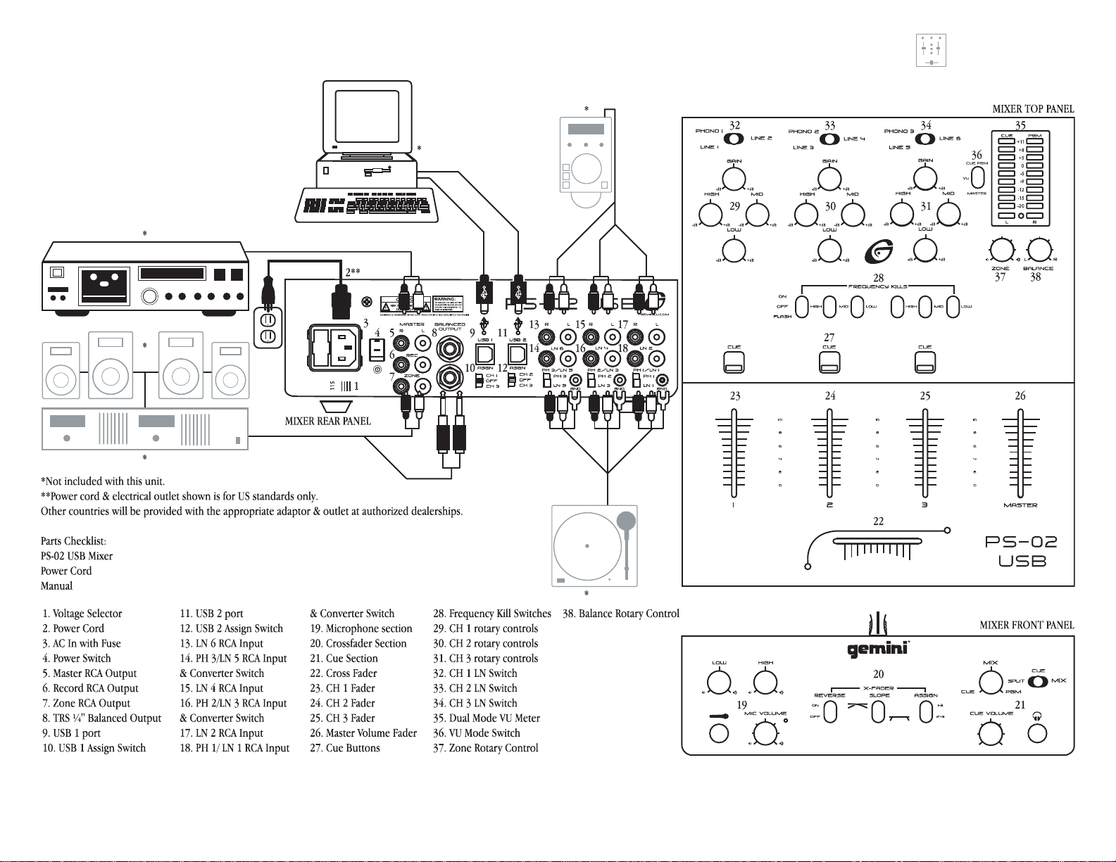
CONNECTIONS:
1. Before plugging this unit into any outlet, make sure that the
OLTAGE SELECTOR (1) is set to the proper voltage. To change the
V
selection, unscrew the hard plastic protective top with a Phillips head
screw driver. Then use a flat head screw driver to move the switch to the
proper selection (115 V/230 V).
2. Ensure that the P
making any connections. This unit comes with a P
Plug the P
OWER CORD (2) into the rear panel AC IN WITH FUSE (3) jack
OWER SWITCH (4) is in the OFF position prior to
OWER CORD (2).
before plugging it into a proper power source.
NOTE: LOCATED BY THE AC IN WITH FUSE (3) IS A 250 V FUSE TO
PROTECT AGAINST ELECTRICAL SURGES
A FLAT HEAD SCREWDRIVER INTO THE GROOVE LOCATED INSIDE THE AC
IN WITH FUSE
A
250 V FUSE.
(3) & POP THE FUSE OUT. REPLACE THE FUSE WITH ONLY
. TO REPLACE THE FUSE, PLACE
3. The PS-02 USB has six outputs located on the rear panel:
- The PS-02 USB features two USB P
ORTS (9, 11) to connect the
mixer to any Mac or PC USB (1.0 or greater) ports allowing the DJ
to either record a session onto any wave form editing software pro-
gram or add computer based DJing or audio programs, .MP3, .WMA, .WAV,
or .AIFF formatted music into the mix. The USB P
ORTS (9, 11) inputs
receive audio playback signals from a computer.
- The M
ASTER RCA OUTPUT (5) connects the mixer to your main
amplifier using standard audio cables with RCA-type connectors.
- The RECORD RCA OUTPUT (6) jacks can be used to connect the
mixer to the record input of your recording unit, thus enabling you
to record your mix with RCA cables.
- The Z
ONE RCA OUTPUT (7) jacks allow the connection of an addi-
tional amplifier with RCA cables.
- The TRS ¼" BALANCED OUTPUT (8) connects the mixer to your main
amplifier using standard cables with TRS ¼" connectors. We recommend using balanced cables if the distance to the amplifier is ten feet
or more.
4. Headphones may be plugged into the ¼" jack located in the front
panel’s C
UE SECTION (21).
5. Microphones may be plugged into the ¼" jack located in the front
panel’s MICROPHONE SECTION (19).
6. The PS-02 USB has 3 C
ONVERTIBLE PHONO/LINE (PH/LN) RCA
inputs for channel (CH) 1, CH 2, & CH 3 located on the rear
panel. Facing the rear panel, the convertible RCA input for CH
1 is PH 1/LN 1 (18), for CH 2 is PH 2/LN 3 (16), & for CH 3
is PH 3/LN 5 (14). Using the PH/LN C
ONVERTERS, located just
below each input, you may convert the input from PH to LN &
vice versa. Plug the RCA's from your playable medium into each input to
be connected to their respective channels. The PH I
turntables with a magnetic cartridge. The stereo LN I
NPUTS only accept
NPUTS for CH 1 is LN
2 (17), for CH 2 is LN 4 (15), & for CH 3 is LN 6 (13) only accept line level
inputs such as a CD, DAT, M
er LN S
WITCH (32, 33, 34) setting.
INI DISC, etc. All RCA inputs require the prop-
7. When using (a) turntable(s), you will need to ground the RCA
cable(s) by screwing in the grounding fork(s) to the TRIPLE GROUNDING
SCREWS (GND) located in the rear panel of the PS-02 USB mixer. Attach
each PH ground lines to one of the GND. These are located to the right of
each PH/LN C
NOTE:
ONVERTER.
WHEN USING TURNTABLES, NOT ATTACHING A GROUND MAY CAUSE A SYSTEM
"HUM."
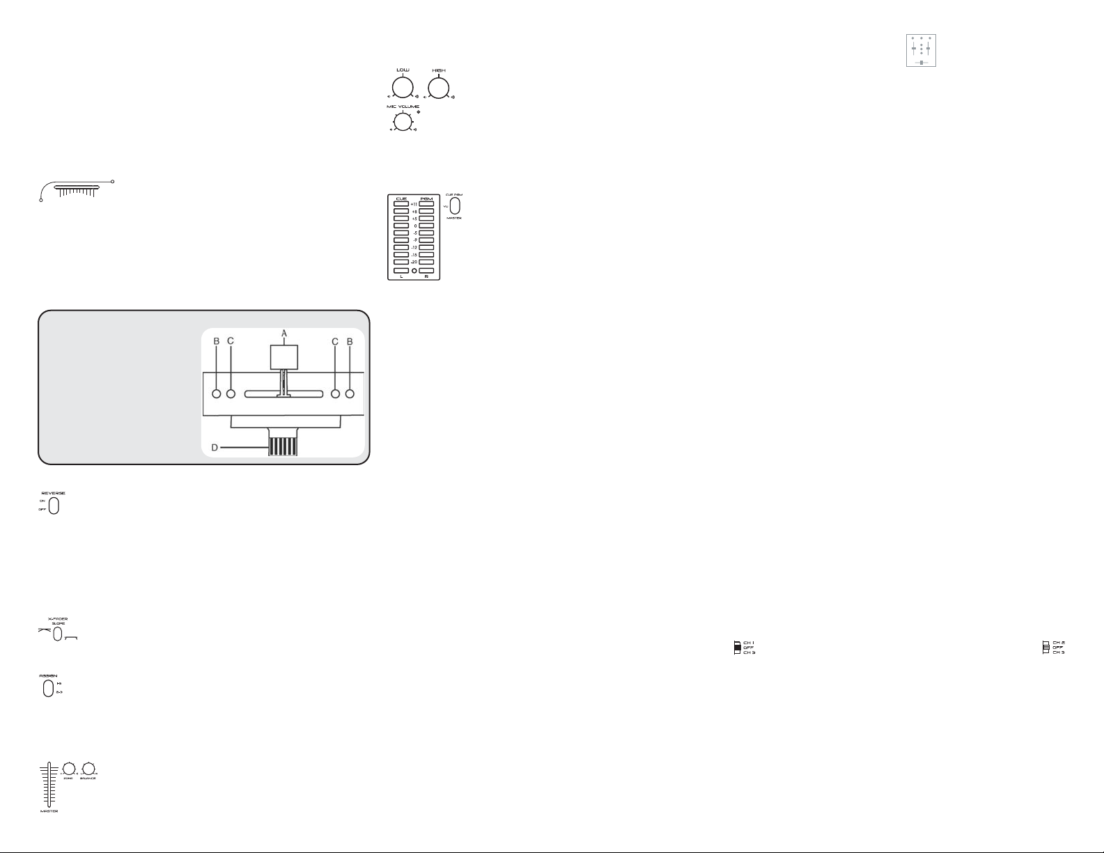
OPERATIONS:
1. Once all of your connections have been made in the rear panel, turn on
the mixer by pressing the P
OWER SWITCH (4).
4
2. CH 1: To bring this channel into program output (PGM),
you must first decide which line will be in use. Use the CH 1
LN S
WITCH (32) to toggle from PH 1/LN 1 (18) to LN 2 (17) on
this channel. Once you've selected the proper line, slowly raise
the CH 1 F
sound output of this channel by adjusting the rotary G
ADER (23) to a comfortable level. You can further modify the
AIN, HIGH, MID, LOW
(29) controls located below the CH 1 LN SWITCH (32).
3. CH 2: To bring this channel into PGM, you must first decide
which line will be in use. Use the CH 2 LN SWITCH (33) to toggle from PH 2/LN 3 (16) to LN 4 (15) on this channel. Once
you've selected the proper line, slowly raise the CH 2 F
ADER
(24) to a comfortable level. You can further modify the sound output of this
channel by adjusting the rotary G
below the CH 2 LN S
WITCH (33).
AIN, HIGH, MID, LOW (30) controls located
4. CH 3: To bring this channel in to PGM, you must first decide
which line will be in use. Use the CH 3 LN S
WITCH (34) to tog-
gle from PH 3/LN 5 (14) to LN 6 (13) on this channel. Slowly
raise the CH 3 F
ADER (25) to a comfortable level, once you've
selected the proper line. You can further modify the sound output of this
channel by adjusting the rotary G
below the CH 3 LN S
FOR OPTIMAL PERFORMANCE, BEGIN PROGRAM MIX WITH ROTARY GAIN CON-
NOTE:
TROLS SET TO MINIMUM & ROTATE IT TO THE COUNTER CLOCKWISE POSITION. MAKE
ALL ADJUSTMENTS IN SOUND OUTPUT WITH THE USE OF YOUR CH FADERS
25),
ZONE (37), BALANCE (38), & MASTER VOLUME (26) CONTROLS. THIS WILL
PREVENT SIGNAL OVERLOAD
YOUR SOUND
MAY ADJUST THE ROTARY GAIN CONTROL IF NEEDED
WITCH (34).
& WOULD LIKE TO INCREASE THE OUTPUT OF YOUR SOUND, THEN YOU
REQUENCY KILLS: There are two ways to kill, or cancel
5. F
AIN, HIGH, MID, LOW (31) controls located
(23, 24,
& DECREASE DISTORTION. ONCE YOU HAVE MODIFIED
.
out, frequencies, only on CH 2 (24) & CH 3 (25), using
the H
IGH, MID, & LOW FREQUENCY KILL SWITCHES (28). Each FREQUENCY KILL
SWITCH (28) has 3 positions: ON, OFF & FLASH. When you move the select-
ed F
REQUENCY KILL SWITCH (28) to the top ON position, the switch will stay
there, & the frequency will be killed. When you move the selected
F
REQUENCY KILL SWITCH (28) to the center position OFF the kill function is
not active, & the frequency will not be killed. When you move the selected
F
REQUENCY KILL SWITCH (28) to the bottom FLASH position & hold it there,
the frequency will be killed. Releasing the selected F
REQUENCY KILL SWITCH
(28) from the bottom position will bring it back to the center position &
the frequency will no longer be killed.
6. C
UE SECTION: By connecting a set of headphones to the ¼" jack in the
C
UE SECTION (21), you can monitor any or all channels.
UE: Press the CUE BUTTONS (27) located above CH 1 (23), CH 2
- C
(24), &/or CH 3 (25) to assign the CH(s) to be monitored in your head-
phones. The respective C
UE VOLUME: Use the front panel located rotary CUE VOLUME con-
- C
UE LED indicators will glow when in use.
trol to adjust the cue volume without changing the overall mix.
- CUE/MIX/PGM: By turning the front panel located CUE/MIX/PGM
rotary control counter clockwise you will be able to monitor the
assigned cue signal. Slowly turning the control clockwise to middle position (M
IX) allows you to monitor your CUE signal mixed with PGM. Moving
the control clockwise to the right allows you to monitor PGM output.
- C
UE SPLIT/MIX: Use the CUE SPLIT/MIX switch to split the
audio input playing in your head phones. When the C
UE
Page 5
SPLIT/MIX switch is in CUE mode you will only be able to monitor your CUE,
when the rotary C
UE/MIX/PGM control is in CUE. When the CUE SPLIT/MIX
switch is in split, you will notice the left side of your headphones will play
your C
UE signal & the right side will play PGM, thus enabling you to mon-
itor both outputs separately. This feature will only work properly if the
C
UE/MIX/PGM rotary control is placed at noon or middle position. If the
C
UE/MIX/PGM rotary control is set to CUE you will only here the CUE signal
playing on the left side of your headphones. If the C
UE/MIX/PGM rotary
control is set to PGM, the PGM will be the only signal heard from the right
side of your headphones.
7. C
ROSS FADER: The CROSS FADER (22) allows you to mix
from one source to another. The C
unit is removable & if the need arises can be easily replaced. Your G
ROSS FADER (22) in your
EMINI
mixer comes with an RG-45 (RAIL GLIDE™) dual-rail cross fader. RAIL
GLIDE™ cross faders have internal dual stainless steel rails that allow the
slider to ride smoothly & accurately from end to end. Also available is our
RG-45 P
RO (PRO GLIDE™) dual-rail cross fader. This unique cross fader fea-
tures, a special curve designed for scratch mixing. Just purchase one from
your G
EMINI dealer & follow the instructions:
USER REPLACEABLE CROSS FADER
1. UNSCREW THE OUTSIDE MIXER FACE
PLATE SCREWS
. THEN REMOVE FADER PLATE
PLATE
SCREWS
CAREFULLY LIFT THE FADER & UNPLUG
2.
THE CABLE
PLUG THE NEW FADER INTO THE CABLE
3.
& PLACE IT BACK IN THE MIXER.
SCREW FADER PLATE TO THE MIXER &
4.
REPLACE THE MIXER FACE PLATE.
8. C
ROSS FADER SECTION (20):
& REMOVE THE FACE
(B & NOT C).
(D).
EVERSE: The REVERSE switch allows you to reverse the CROSS
- R
FADER (22). When REVERSE is activated, the right side CH 2 (24) or
CH 3 (25) is controlled by the left side of the C
ROSS FADER
side CH 1 (23) or CH 2 (24) is controlled by the right side of the C
(22) & the left
ROSS
FADER (22). When REVERSE is inactive, the CROSS FADER (22) functions are
returned to normal.
NOTE: WHEN THE REVERSE SWITCH IS ACTIVATED, ONLY THE CROSS FADER (22)
REVERSES
. THE CHANNEL FADERS (23, 24, 25), KILL SWITCHES (28), GAIN & TONAL
CONTROLS
(29, 30, 31) DO NOT REVERSE.
ADER SLOPE: The X FADER SLOPE switch allows you to adjust
- X F
the kind of curve the C
ROSS FADER (22) has. Flip the X FADER SLOPE
switch up to make the slope steep & cutting (perfect for scratch-
ing). Flip the X F
- A
the C
CH 1 & CH 3 are assigned to the C
ADER SLOPE switch to make the slope gradual & gentle.
SSIGN: The ASSIGN switch is used to place CH(s) on either side of
ROSS FADER (22). When the ASSIGN switch is in the top position,
ROSS FADER (22). When the REVERSE
switch is not activated, CH 1 will be on the left & CH 3 will be on the right.
When the A
assigned to the C
SSIGN switch is in the bottom position, CH 2 & CH 3 are
ROSS FADER (22). When the REVERSE switch is not activat-
ed, CH 2 will be on the left & CH 3 will be on the right.
9. OUTPUT SELECTION CONTROL: Once you are comfortable
with the sound level of your music you may adjust the volume with the
M
ASTER VOLUME FADER (26) control. You may adjust the volume of the
zone output with the Z
audio output from left to right with the B
ONE ROTARY CONTROL (37). You may also pan the
ALANCE ROTARY CONTROL (38).
IC SECTION (19): Plug your main MIC into the 1/4" MIC
10. M
JACK located on the front panel. Connecting a microphone
to the 1/4" M
mixer to the stereo receiver through the O
This M
IC is controlled by the MIC VOLUME, HIGH, & LOW rotary con-
trols. To activate the M
IC JACK allows voice amplification through the
UTPUTS (5, 6, 7, 8, 9, 11).
IC SECTION (19), raise the level of the MIC VOLUME.
The rotary knob will click & a green LED will light up to indicate that the
M
IC is in use. To turn off the MIC SECTION (19), lower the MIC VOLUME rotary
knob until it clicks & the LED turns off.
11. VU M
M
of C
UE & PGM or left & right stereo levels of the master out-
put. With the VU M
put level of the C
mode is engaged the C
D
UAL MODE VU METER (35), while the PGM will be located on
ETER: The PS-02 USB has a DUAL MODE VU
ETER (35) that allows you to monitor the decibel levels
ODE SWITCH (36) you may monitor the out-
UE & PGM when the switch is UP. When this
UE will be located on the left of the
the right. Or you can monitor the left & right stereo decibel levels of the
PGM output when the switch is D
OWN.
USB OPERATION:
The PS-02 USB is compatible with any audio software program & media
player. You can utilize the USB P
ORTS (9, 11) to play files stored on your
computer through the mixer with the same control features as you would
playing through a CD player or turntable. Or you can record a live session
onto almost any audio software program to burn on a CD at a later time.
Each port can record & play at the same time.
S
YSTEM REQUIREMENTS:
- PC Windows 98 SE, ME, 2000, XP, or XP Professional with at least one
USB port
- Mac OS 9.1 or X with at least one USB port
- USB 1.0 or greater
PLEASE CHECK THAT THE MIXER CHASSIS & COMPUTER CHASSIS ARE CON-
NOTE:
NECTED TOGETHER IN THE GROUNDING SYSTEM.
OR MAC:
F
1. Turn on your computer & PS-02 USB mixer.
2. Connect the USB P
ORTS (9, 11) on your mixer to the USB ports on your
computer via USB cable.
3. Select the APPLE icon.
4. Select S
YSTEM PREFERENCES.
5. Select the SOUND icon.
6. Select O
UTPUT box to monitor the computer through the mixer or INPUT
box to record onto the computer through the mixer.
7. Select USB CODEC or USB AUDIO DEVICE.
8. You can begin playing audio from iTunes, Quicktime, or any other media
player available on your system.
To eliminate your computer’s sound effects from running through the
mixer transfer the computer's signal to the internal speakers:
1. Select the A
PPLE icon.
2. Select SYSTEM PREFERENCES.
3. Select S
4. Select S
OUND icon.
OUND EFFECTS.
5
ps-02usb
5. Select P
6. Select I
7. Keep SOUND open to access this area often.
F
1. Turn on your computer & PS-02 USB mixer.
2. Connect the USB P
computer via USB cable. Windows will recognize & automatically install
the necessary drivers & you can begin playing audio from any other media.
1. Select START menu.
2. Select C
3. Select S
4. Select A
5. Select S
choose USB A
is connected.
6. Select S
into the computer & choose USB A
more than one device is connected.
7. Be sure the USE ONLY DEFAULT DEVICES is not checked.
8. A
9. Keep the CONTROL PANEL open to access this area often.
mixer transfer the computer's signal to the internal speakers:
1. In the C
2. Select S
3. In the scroll down menu for SOUND SCHEME select NO SOUND.
4. A
5. Select OK.
your system.
NOTE:
SOFT WARE PROGRAM
NOTE:
DEFAULT HAS THE VOLUME LEVELS SET AT HALF
ADJUST THE VOLUME ACCORDING TO YOUR NEEDS.
USB ASSIGN:
coming in through the mixer can be assigned to a channel. After making
your connections, you must adjust the USB A
the channel you will be using. USB 1 (9) can be controlled by CH 1 or CH
3. USB 2 (11) can be controlled by CH 2 or CH 3.
1. USB 1 (9) can be assigned to CH 1, CH 3, or turned O
F
ADER (23), GAIN & EQ CONTROLS (29) & CUE SECTION (21, 27) when CH 1
is assigned to USB 1 (9).
F
ADER (25), GAIN & EQ CONTROLS (31) & CUE SECTION (21, 27) when CH 3
LAY ALERTS & SOUND EFFECTS THROUGH scroll down menu.
NTERNAL SPEAKERS.
OR PC:
ORTS (9, 11) on your mixer to the USB ports on your
If sound is not playing through the mixer:
ONTROL PANELS.
OUNDS & AUDIO DEVICES.
UDIO tab.
OUND PLAYBACK for computer sounds through the mixer &
UDIO CODEC or USB AUDIO CODEC [2] if more than one device
OUND RECORDING for external sounds recorded through the mixer
UDIO CODEC or USB AUDIO CODEC [2] if
PPLY the settings.
To eliminate your computer’s sound effects from running through the
ONTROL PANELS select SOUNDS & AUDIO DEVICES.
OUNDS tab.
PPLY the settings.
You can begin playing audio from any other media player available on
WHEN USING ADUIO SOFT WARE YOU MUST ADJUST THE PREFERENCES OF THE
.
WHEN ADDING THE PS-02USB TO YOUR SOUND DEVICE THE COMPUTER’S
. ENTER YOUR AUDIO SETTINGS &
The USB PORTS (9, 11) have USB ASSIGN SWITCHES (10, 12)
located below each port so playback signals from the computer
SSIGN SWITCHES (10, 12) for
.
FF
During playback, the signal from the computer will be sent into the CH 1
During playback, the signal from the computer will be sent into the CH 3
Page 6

is assigned to USB 1 (9).
2. USB 2 (11) can be assigned to CH 2, CH 3, or turned O
FF.
During playback, the signal from the computer will be sent into the CH 2
F
ADER (24), GAIN & EQ CONTROLS (30) & CUE SECTION (21, 27) when CH 2
is assigned to USB 2 (11).
During playback, the signal from the computer will be sent into the CH 3
F
ADER (25), GAIN & EQ CONTROLS (31) & CUE SECTION (21, 27) when CH 3
is assigned to USB 2 (11), the signal coming from CH 3, PH 3/LN 5 (14)
or LN 6 (13).
You should turn O
FF each port if you are not sending music from your
computer through the mixer via USB cables. Monitoring the computer’s
audio signal through the USB P
selected on the USB A
SSIGN SWITCHES (10, 12).
ORTS (9, 11) is not allowed when OFF is
RECORDING VIA USB:
This mixer is compatible with most wave editing software programs. You
may record from each USB PORT (9, 11) simultaneously onto the computer regardless of the USB assignment. When recording onto your computer, the signal coming from CH 1 (17, 18) will be sent to the computer via
USB 1 P
R
When the USB A
ORT (9). The signal coming from PGM outputs (MASTER (5),
ECORD (6), ZONE (7)) will be sent to the computer via USB 2 PORTS (11).
SSIGN SWITCHES (10, 12) are OFF you may still record onto
the computer.
SPECIFICATIONS:
NPUTS:
I
Phono...................................................................................3 mV, 47 KOhm
Line..................................................................................150 mV, 27 KOhm
MIC.....................................................................1.5 mV, 1 K Ohm Balanced
MIC Bass.........................................................................................± 12 dB
MIC High........................................................................................± 12 dB
O
UTPUTS:
Amp/Zone.......................................................................0 dB 1 V, 400 Ohm
Max...................................................................................20 V Peak-to-Peak
Rec.....................................................................................225 mV, 5 KOhm
Balanced Master......................................................................2 V, 400 Ohm
G
ENERAL:
Frequency Response................................................20Hz - 20KHz +/- 2 dB
Distortion.......................................................................................< 0.02%
S/N Ratio..........................................................................Better Than 80 dB
Headphone Impedance...................................................................16 Ohm
Power Source......................................................115/230 V, 60/50 Hz, 20 W
Unit Dimensions.............................................................10" x 3.3" x 10.25"
.....................................................................................(254 x 84 x 260 mm)
Weight...............................................................................8.84 .lbs (4.01kg)
S
PECIFICATIONS SUBJECT TO CHANGE WITHOUT NOTIFICATION FOR IMPROVEMENT.
NOTES:
___________________________________________________________________________________________________________
___________________________________________________________________________________________________________
___________________________________________________________________________________________________________
___________________________________________________________________________________________________________
___________________________________________________________________________________________________________
___________________________________________________________________________________________________________
___________________________________________________________________________________________________________
___________________________________________________________________________________________________________
___________________________________________________________________________________________________________
___________________________________________________________________________________________________________
___________________________________________________________________________________________________________
___________________________________________________________________________________________________________
___________________________________________________________________________________________________________
___________________________________________________________________________________________________________
___________________________________________________________________________________________________________
___________________________________________________________________________________________________________
___________________________________________________________________________________________________________
___________________________________________________________________________________________________________
___________________________________________________________________________________________________________
___________________________________________________________________________________________________________
___________________________________________________________________________________________________________
___________________________________________________________________________________________________________
___________________________________________________________________________________________________________
___________________________________________________________________________________________________________
___________________________________________________________________________________________________________
___________________________________________________________________________________________________________
___________________________________________________________________________________________________________
___________________________________________________________________________________________________________
___________________________________________________________________________________________________________
___________________________________________________________________________________________________________
___________________________________________________________________________________________________________
___________________________________________________________________________________________________________
___________________________________________________________________________________________________________
___________________________________________________________________________________________________________
___________________________________________________________________________________________________________
___________________________________________________________________________________________________________
___________________________________________________________________________________________________________
For Your Records Serial #:
6
Page 7

ACHTUNG!
BITTE UNBEDINGT VOR BENUTZUNG DES GERÄTS LESEN!
WICHTIGE HINWEISE UND SICHERHEITSANWEISUNGEN
GEFAHR EINES ELEKTRISCHEN SCHLAGS. GERÄT NICHT ÖFFNEN!
VORSICHT: Dieses Produkt erfüllt die FCC-Regeln, wenn Sie zum
Anschluss abgeschirmte Kabel und Stecker verwenden, um es mit anderen
Geräten zu verbinden. Auch um elektromagnetische Störungen anderer
elektrischer Geräte wie Radios oder Fernseher zu vermeiden, benutzen Sie
abgeschirmte Kabel und Stecker für die Verbindungen.
Das Ausrufezeichen im gleichseitigen Dreieck weißt Sie in der
Bedienungsanleitung auf wichtige Bedienungsanweisungen und Wartungs/Serviceanweisungen hin.
Das Blitzsymbol im gleichseitigen Dreieck dient dazu, den Benutzer vor
gefährlichen Spannungen an nicht isolierten Stellen im Gehäuse zu warnen, die so groß sind, dass Sie eine Gefahr für den Benutzer darstellen.
ANWEISUNGEN LESEN: Lesen Sie alle Sicherheits- und
Bedienungsanweisungen, bevor Sie mit dem Produkt arbeiten.
AUFBEWAHRUNGSHINWEIS: Bewahren Sie alle Sicherheits- und
Bedienungsanweisungen gut auf.
WARNHINWEISE: Alle Warnhinweise für das Produkt und die
Bedienungsanweisungen müssen genau eingehalten werden.
ANWEISUNGEN BEFOLGEN: Alle Anweisungen zum Betrieb des Produkts
sollten befolgt werden.
REINIGUNG: Das Produkt sollte nur mit einem Polier- oder einem
weichen trockenen Tuch gereinigt werden. Benutzen Sie dazu niemals
Möbelwachs, Benzine, Insektenmittel oder andere flüchtige
Reinigungsmittel, denn Sie könnten zur Korrosion des Gehäuses führen.
ERWEITERUNGEN: Benutzen Sie keine Erweiterungen, die nicht vom
Hersteller empfohlen sind, da sie zu Risiken führen könnten.
WASSER&FEUCHTIGKEIT: Benutzen Sie dieses Produkt nicht in der Nähe
von Wasser, z. B. in der Nähe einer Badewanne, einer Waschschüssel, eines
Küchenspülbeckens eines Waschbeckens, in einem feuchten Keller, einem
Schwimmbecken oder an ähnlichen Orten.
ZUBEHÖR: Stellen Sie das Produkt nicht auf eine wackelige und labile
Unterlage. Das Produkt könnte herunterfallen und dabei Kinder oder
Erwachsene verletzen, wie auch selber beschädigt werden. Stellen Sie das
Produkt nur auf vom Hersteller empfohlene oder verkaufte Unterlagen.
Jede Befestigung und Montage des Produkts sollte nach den Anweisungen
des Herstellers ausgeführt werden. Nutzen Sie dazu ein vom Hersteller
empfohlenes Montageset.
MOBILE UNTERLAGEN: Bewegen Sie eine Kombination aus dem Produkt
und einer mobilen Unterlage mit Vorsicht. Schnelles Anhalten, zu viel
Schub oder unebene Böden können dazu führen, dass sich Produkt und
mobile Unterlage überschlagen (S
IEHE BILD A).
BELÜFTUNG: Schlitze und Öffnungen im Gehäuse sind für die Belüftung
vorgesehen. Sie stellen den zuverlässigen Betrieb des Produkts sicher und
schützen es vor Überhitzung. Diese Öffnungen dürfen nicht verschlossen,
blockiert oder bedeckt werden. Stellen Sie deswegen das Produkt niemals
auf ein Bett, ein Sofa, einen Teppich oder Stellen mit ähnlicher Oberfläche.
Wenn Sie dieses Produkt in einer festen Installation wie z. B. in einem Regal
oder einem Rack einbauen, sorgen Sie für ausreichende Belüftung oder
sorgen Sie dafür, dass die Bestimmungen des Herstellers genau eingehalten werden.
STROMANSCHLUSS: Dieses Produkt darf nur mit dem auf dem Gerät
angegebenen Strom betrieben werden. Wenn Sie sich nicht sicher sind,
welche Stromart Sie bei sich zuhause haben, fragen Sie den Verkäufer des
Geräts oder Ihren Stromversorger.
AUFSTELLUNGSORT: Stellen Sie das Gerät an einem festen Ort auf.
ZEITEN DES NICHTGEBRAUCHS: Ziehen Sie das Stromkabel aus dem
Gerät heraus, wenn Sie es für eine längere Zeit nicht gebrauchen.
ERDUNG ODER POLUNG:
- Wenn dieses Produkt mit einem gepolten Wechselstromstecker (Ein
Stecker mit einem Kontakt mehr als andere Stecker) ausgestattet ist, passt
dieser nur in einer bestimmten Richtung in die Steckdose und ist ein
besonderes Sicherheitsmerkmal. Sollten Sie den Stecker nicht komplett in
die Steckdose stecken können, versuchen Sie ihn andersherum einzustecken. Sollte der Stecker auch dann noch nicht in die Steckdose passen, beauftragen Sie einen Elektriker, um diese veraltete Steckdose auszutauschen.
- Wenn dieses Produkt mit einem geerdeten dreipoligen Stecker ausgestattet ist, hat der Stecker einen dritten (Erdungs-)Kontakt und passt nur in
eine Steckdose mit entsprechender Erdung. Auch das ist ein
Sicherheitsmerkmal. Sollte der Stecker nicht in die Steckdose passen,
beauftragen Sie einen Elektriker, um diese veraltete Steckdose auszutauschen.
SCHUTZ DES STROMKABELS: Stromkabel sollten so verlegt werden, dass
man nicht auf sie treten kann noch dass sie von darauf stehenden oder
gegen sie stoßenden Gegenständen gequetscht werden. Achten Sie besonders auf Kanten, Sicherung, Stecker und Buchsen.
AUSSENANTENNENERDUNG: Wenn Sie eine Außenantenne oder ein
Radio-/Fernsehkabelsignal an das Produkt anschließen, achten Sie darauf,
dass die Antenne oder das Kabel geerdet sind, um dafür zu sorgen, dass
Überspannungen und elektrostatische Aufladungen nicht auftreten können. Im Artikel 810 des National Electrical Code, ANSI/NFPA 70, finden Sie
Informationen über die richtige Erdung des Antennenmasts und weitere
Informationen zu diesem Thema. (S
IEHE AUCH ABBILDUNG B).
GEWITTER: Trennen Sie das Produkt während eines Gewitters oder wenn
es unbeaufsichtigt ist oder wenn es für eine lange Zeit nicht benutzt wird
durch Ziehen des Stromkabels vom Stromnetz. Trennen Sie auch die
Verbindung zu einer Antenne oder Radio-/Fernsehkabeln. Dadurch vermei-
7
PS-02USB
den Sie Beschädigungen des Produkts durch Blitze oder Überspannungen.
STROM- UND ÜBERLANDLEITUNGEN: Stellen Sie eine Außenantenne
nicht in der Nähe von Überlandleitungen, elektrischen Licht- oder
Stromkreisen oder an Stellen, wo sie in eine solche Leitung fallen könnte
auf. Wenn Sie eine Außenantenne aufstellen, achten Sie besonders darauf,
dass Sie auf keinen Fall irgendwelche Stromleitungen berührt. Das kann zu
gefährlichen Auswirkungen führen.
ÜBERLASTUNG: Überlasten Sie keine Steckdosen, Verlängerungskabel
oder Sicherungen. Das kann zu Bränden oder elektrischen Schlägen
führen.
EINDRINGEN VON GEGENSTÄNDEN ODER FLÜSSIGKEIT: Führen Sie
niemals irgendwelche Gegenstände durch Öffnungen in das Produkt ein.
Sie könnten mit Strom führenden Stellen in Verbindung kommen oder
Kurzschlüsse verursachen, die zu Bränden oder elektrischen Schlägen
führen können. Gießen Sie niemals irgendwelche Flüssigkeiten auf oder in
das Produkt.
SERVICE: Versuchen Sie nicht, das Produkt selber zu reparieren. Durch
das Öffnen des Gehäuses oder Entfernen von Schrauben können Sie mit
gefährlichen Spannungen oder anderen Risiken in Kontakt kommen.
Beauftragen Sie im Reparaturfall nur qualifiziertes Servicepersonal.
WANN SERVICE NÖTIG IST: Unter den folgenden Bedingungen ziehen
Sie auf jeden Fall das Stromkabel aus der Steckdose und beauftragen Sie
für eine Reparatur nur qualifiziertes Servicepersonal:
- Wenn das Stromkabel defekt ist.
- Wenn Flüssigkeit auf oder in das Produkt gelaufen ist oder Gegenstände
in das Produkt gefallen sind.
- Wenn das Produkt Regen oder Wasser ausgesetzt war.
- Wenn das Produkt trotz Befolgen der Bedienungsanweisungen nicht
normal arbeitet. Stellen Sie dabei das Produkt nur nach den Anweisungen
der Bedienungsanleitung ein, andere Einstellungen können das Produkt
beschädigen und den aufwändigen Einsatz von Technikern für die
Wiederherstellung erfordern.
- Wenn das Produkt hingefallen oder auf andere Art und Weise beschädigt
ist.
- Wenn das Produkt eine eindeutige Veränderung im Betrieb zeigt.
ERSATZTEILE: Wenn Ihr Produkt Ersatzteile benötigt, achten Sie darauf,
dass der Servicetechniker nur vom Hersteller erlaubte Ersatzteile oder
Ersatzteile, die die gleichen Eigenschaften wie die originalen Teile
aufweisen, einsetzt. Falsche Ersatzteile können zu Bränden, elektrischen
Schlägen oder anderen Risiken führen.
SICHERHEITSTEST: Bevor der Service oder eine Reparatur für dieses
Produkt beendet sind, beauftragen Sie den Servicetechniker, einen
Servicetest durchzuführen, um sicher zu stellen, dass das Produkt einwandfrei funktioniert.
WAND- ODER DECKENMONTAGE: Das Produkt sollte nicht an einer
Wand oder der Decke montiert werden.
HITZE: Stellen Sie das Produkt nicht in die Nähe von Wärmequellen wie
Radiatoren, Wärmespeichern, Öfen oder anderen Produkten (auch
Verstärker), die Hitze erzeugen.
Page 8

8
Page 9

PROFESSIONELLER 10" 3-KANAL-STEREO-MIXER
EINFÜHRUNG:
Vielen Dank, dass Sie sich für einen P
(U
NIVERSAL SERIAL BUS) 10" 3-KANAL-STEREO-MIXER entschieden haben.
ROFESSIONELLEN GEMINI-PS-02 USB
Dieser State-of-the-art-Mixer ist nach dem neuesten Stand der Technik
hergestellt und mit einer Garantie von 3 Jahren versehen. Der Crossfader
hat eine Garantie von 90 Tagen. Bitte lesen Sie alle Anweisungen vor der
Inbetriebnahme sorgfältig durch.
AUSSTATTUNG:
- 10" 3-Kanal-Stereo-Mixer
- 8 Line-Eingänge mit 6 Cinch-Buchsen, 3 umschaltbare Phono/LineCinch-Buchsen und 2 USB-Anschlüsse für PC
- 2 USB-Anschlüsse
- USB-Anschlüsse ermöglichen das direkte Aufnehmen der am Mixer
anliegenden Signale mit einem PC oder Mac ohne zusätzliche Hardware.
- Audiosignale jeden Formats können vom Computer mit CDs und
Schallplatten via USB gemischt werden
- gleichzeitige Aufnahme und Wiedergabe über USB möglich
- Master-, Record- und Zone-Ausgänge mit Cinch-Buchsen
- Zusätzliche symmetrische 6.3-mm-Klinken-Ausgänge
- 3 Erdungsschrauben für einfachen Anschluss
ORDERSEITE:
V
- Abnehmbare Deckplatte ermöglicht den einfachen Austausch des Rail
Glide-Crossfaders durch den Benutzer.
- 3-Band-Kill-Switches mit Flash-Effekt
- 3-Band-EQ mit Drehreglern mit Cut-Möglichkeit & Gain-Drehregler pro
Kanal
- Beleuchtete Push-Taster in der Cue-Sektion
- Drehregler für Zone und Balance
- Zweifache VU-Meter mit hellen LEDs und umschaltbaren Anzeigemodi
- Mastervolume-Fader
BERSEITE:
O
- 6.3-mm-Klinkenbuchsen für Kopfhöreraus- und Mikrofoneingang
- Cue-Sektion mit Cue-Lautstärkedrehregler und Cue-/PGM-Regler mit
Split/Cue/Mix-Schalter
- Mikrofon-Sektion mit Drehregler für Mikrofonlautstärke, Höhen- und
Bassregler für Mikrofon-EQ
- Fader-Sektion mit Hamster-/Reverse-Schalter, Slope- und AssignSchaltern
VORSICHTSMASSNAHMEN:
1. Vor der Anwendung des Mixers, bitte alle Anweisungen durchlesen.
2. Um einen elektrischen Schlag zu vermeiden, das Gerät nicht öffnen.
Servicearbeiten dürfen nur qualifizierten Wartungstechnikern durchgeführt werden.
3. Setzen Sie das Gerät nie direkter Sonneneinstrahlung oder Hitzequellen
(Heizstrahler o. Ä.) aus.
4. Reinigen Sie die Oberflächen nur mit einem weichen Tuch. Keine scharfen Reinigungsmittel verwenden.
5. Transportieren Sie den Mixer möglichst im Originalkarton, um Schäden
zu vermeiden.
ETZEN SIE DIESES GREAT NIE REGEN ODER STARKER FEUCHTIGKEIT AUS.
6. S
ERWENDEN SIE KEIN KONTAKT-, ÖL- ODER SILIKONSPRAY AN DEN SCHALTERN,
7. V
REGLERN UND FADERN.
ANSCHLÜSSE:
1. Bevor Sie den Mixer an eine Steckdose anschließen, stellen Sie
sicher, dass der V
OLTAGE SELECTION SWITCH (1)
(Spannungswahlschalter) auf die richtige vorhandene Netzspannung
eingestellt ist. Um die Einstellung zu ändern, lösen Sie die Schraube der
Plastiksicherung mit einem Kreuzschlitzschraubendreher und drehen sie
die Plastiksicherung zur Seite. Schieben Sie nun mit einem schmalen
Schlitzschraubendreher den Spannungswahlschalter in die richtige
Position (115 V/230 V).
2. Vergewissern Sie sich, dass sich der Netzschalter P
OWER SWITCH (4)
in der Aus-Position befindet, bevor Sie den Mixer anschließen.
Stecken Sie das mitgelieferte Netzkabel P
OWER CORD (2) in die Netzbuchse
AC IN WITH FUSE (3), bevor Sie es in eine passende Steckdose stecken.
ANMERKUNG:
TER MIT EINER 250-V-NETZSICHERUNG INTEGRIERT, DIE VOR ELEK-
TRISCHEN üBERSPANNUNGEN SCHÜTZ. ZUM AUSTAUSCHEN DER
SICHERUNG STECKEN SIE EINEN SCHLITZSCHRAUBENDREHER IN DIE
INNERE AUSBUCHTUNG DER NETZBUCHSE (3) UND DRÜCKEN SIE DEN SICHERUNG-
SHALTER HERAUS. ERSETZEN SIE DIE SICHERUNG DURCH EINE NEUE GLEICHEN T YPS.
IN DIE NETZBUCHSE (3) IST EIN SICHERUNGSHAL-
3. Der PS-02 USB hat sechs Ausgänge, die sich auf der Rückseite befinden.
- Der PS-02 USB verfügt über zwei USB-Anschlüsse USB P
ORTS
(9, 11), um den Mischer mit jedem Mac oder PC mit einem USB-
Anschluss (1.0 oder höher) zu verbinden. Dadurch ist es DJs
möglich, ihre Session mit jeder Audio-Editing-Software aufzunehmen oder
mit Computer basierten DJing oder Audioprogrammen Musik in den
Formaten MP3, WMA, WAV oder AIFF in seinen Mix einzubeziehen. Die
USB-Anschlüsse USB P
ORTS (9, 11) nehmen vom Computer über USB
abgespielte Audiosignale auf.
- Die Cinch-Ausgänge M
ASTER OUTPUT (5) dienen zum Anschluss
an den Hauptverstärker mit Standardkabeln.
- Die Cinch-Buchsen R
EC RCA OUTPUT (6) sind für den Anschluss
an ein Aufnahmegerät vorgesehen. Dadurch ist es ebenfalls
möglich, eine Session auf ein geeignetes Aufnahmegerät aufzunehmen.
- Die Cinch-Buchsen Z
ONE RCA OUTPUT (7) können zum Anschluss
eines zweiten Verstärkers verwendet werden.
- Die 6.3-mm-Klinkenbuchsen B
ALANCED OUTPUT (8) dienen zum
Anschluss an den Hauptverstärker mit symmetrischen
Klinkenkabeln. Wir empfehlen bei Entfernungen von mehr als 3 m
die Verwendung von symmetrischen Kabeln.
4. Kopfhörer können an die 6.3-mm-Klinkenbuchse in der C
SECTION (21) an der Frontseite angeschlossen werden.
5. Ein Mikrofon kann an die 6.3-mm-Klinkenbuchse in der
ICROPHONE SECTION (19) angeschlossen werden.
M
6. Der PS-02 USB hat drei umschaltbare P
HONO/LINE- (PH/LN) Cinch-
Eingänge für die Kanäle 1, 2 und 3. Diese befinden sich auf der
Rückseite. Schaut man auf die Rückseite, sind die Cinch-
Buchsen PH 1/LN 1 (18) für Kanal 1, PH 2/LN 3 (16) für Kanal 2 und PH
9
ps-02usb
3/ LN 5 (14) für Kanal 3. Die Umschaltung erfolgt mit den,
unterhalb der Cinch-Buchsen befindlichen Schaltern PH/LN.
Verbinden Sie Ihr Abspielgerät mit einem Cinch-Kabel mit dem
Eingang des gewünschten Kanals. An die Phono-Eingänge PH
NPUTS können nur Plattenspieler mit Magnetsystem
I
angeschlossen werden. Die Line-Eingänge STEREO LN INPUTS (LN 2 (17) für
KANAL 1, LN 4 (15) für KANAL 2 und LN 6 (13) für KANAL 3) dienen zum
Anschluss von CD-, DAT-, MINI-DISC- oder MP3-PLAYERN mit Line-Signalen.
Achten Sie darauf, dass die Wahlschalter LN S
eiligen Cinch-Eingänge in der richtigen Position stehen.
7. Wenn Sie einen oder mehrere Plattenspieler an den Mixer
anschließen, müssen Sie ein zusätzliches Erdungskabel an die
Erdungsschraube des jeweiligen Kanals (jeweils rechts neben den Phono/Line-Umschaltern) an der Rückseite des PS-02 USB anschließen.
ANMERKUNG:
BETRIEBEN, KÖNNEN ERUMMGERÄUSCHE AUFTRETEN.
WIRD EIN PLATTENSPIELER OHNE MASSEVERBINDUNG (ERDUNG)
BEDIENUNG:
1. Wenn alle Verbindungen auf der Rückseite hergestellt sind, schalten Sie
den Mixer mit dem Schalter P
ANAL 1 (CH 1): Um diesen Kanal hören zu können, wählen
2. K
OWER SWITCH (4) ein.
Sie den gewünschten Eingang mit dem Schalter LN S
(32) zwischen PH 1/LN 1 (18) oder LN 2 (17) aus. Nun können Sie mit dem Regler GAIN und dem CH 1 FADER (23) den
Lautstärkepegel und mit den Reglern HIGH, MID und LOW den Klang des
Signals beeinflussen.
ANAL 2 (CH 2): Um diesen Kanal hören zu können, wählen
3. K
Sie den gewünschten Eingang mit dem Schalter LN SWITCH
(33) zwischen PH 2/LN 3 (16) und LN 4 (15) aus. Nun können
Sie mit dem Regler GAIN und dem CH 2 FADER (24) den
Lautstärkepegel und mit den Reglern H
Signals beeinflussen.
ANAL 3 (CH 3): Um diesen Kanal hören zu können, wählen
4. K
Sie den gewünschten Eingang mit dem Schalter LN SWITCH
(34) zwischen PH 3/LN 5 (14) und LN 6 (13) aus. Nun können Sie mit dem Regler GAIN und dem CH 3 FADER (25) den
Lautstärkepegel und mit den Reglern HIGH, MID und LOW den Klang des
Signals beeinflussen.
ANMERKUNG:
DREHREGLER AUF DIE NULLPOSITION UND DREHEN SIE DANN SCHRITT WEISE IM
UHRZEIGERSINN
BEREICH GERADE NICHT ERREICHEN. JETZT IST DER PEGEL RICHTIG EINGESTELLT.
UE
DEN EIGNTLICHEN AUSGANGPEGEL STELLEN SIE MIT DEN KANAL-FADERN (23, 24,
DEM BALANCE-REGLER (38) UND DEM MASTERVOLUME-REGLER (26) EIN.
25),
DADURCH VERMEIDEN SIE ÜBERSTEUERUNGEN UND VERZERRUNGEN. ERHÖHEN SIE
DIE GAIN
GEREGELTER FADER SU NIEDRIG IST
UM EINEN OPTIMALEN KLANG ZU ERZIELEN STELLEN SIE DIE GAIN-
, BIS LAUTE STELLEN AUF DER VU-ANZEIGE DEN ÜBERSTEUERUNGS-
-EINSTELLUNGEN NUR WENN DIE AUSGANGSLAUTSTÄRKE TROTZ HOCH
.
REQUENCY KILLS (AUSLÖSCHEN VON
5. F
FREQUENZBEREICHEN): KANAL 2 (24) und 3 (25) sind mit
WITCH (32, 33, 34) für die jew-
IGH, MID und LOW den Klang des
WITCH
Page 10

einer Kill-Sektion ausgestattet. Die Kill-Schalter LOW, MID, und HIGH (28)
haben drei Stellungen: ON, OFF und FLASH. Bewegen Sie einen der Schalter
in die Stellung O
Frequenzbereich wird ausgeblendet. In der Mittelstellung O
N, bleibt der Schalter in dieser Stellung und der jeweilige
FF ist die Kill-
Funktion nicht aktiv und die Frequenzen des jeweiligen Bereichs werden
nicht beeinflusst. Bewegen Sie den Schalter in die Position F
LASH und hal-
ten ihn fest, so wird der Frequenzbereich ausgeblendet. Lassen Sie den
Schalter wieder los, springt er in die Mittelstellung zurück (O
FF) und die
Kill-Funktion ist wieder deaktiviert. Damit können Sie durch schnelle
rhythmische Bewegungen des Schalters passend zum Tempo eines Songs
Frequenzen unterdrücken und interessante Effekte erzielen.
6. V
ORHÖREN (CUE): Wenn Sie einen Kopfhörer an die Buchse HEADPHONE
in der CUE-SECTION (21) anschließen, können Sie einen oder alle Kanäle
vorhören.
UE-TASTE: Drücken Sie die CUE-TASTE (27) des jeweiligen KANALS 1,
- C
2 oder 3 (23, 24, 25), um den jeweils abzuhörenden Kanal
anzuwählen. Die jeweils zugehörige C
UE-VOLUME: Mit dem Drehregler CUE-VOLUME auf der Frontseite
- C
UE-LED leuchtet dann auf.
stellen Sie die gewünschte Abhörlautstärke ein, ohne das
Ausgangssignal zu beeinflussen.
UE/MIX/PGM: Drehen Sie den Regler CUE/MIX/PGM auf der
- C
Frontseite ganz nach links, so hören Sie nur das Signal des
gewählten Kanals (C
UE). Je weiter Sie nun nach rechts (Uhrzeigersinn)
drehen, umso stärker hören Sie zusätzlich das Ausgangssignal (PGM), bis
am Rechtsanschlag das CUE-SIGNAL nicht mehr und nur noch das
Ausgangssignal (PGM) hörbar ist.
PLIT/MIX: Um das Signal im Kopfhörer zu trennen, verwen-
- S
den Sie den Schalter SPLIT/MIX SWITCH. Im MIX-MODUS hören
Sie die Signale im Kopfhörer, wie oben beschrieben. Steht der Schalter
SPLIT/MIX SWITCH auf SPLIT, hören Sie auf einer Seite des Kopfhörers das
UE-SIGNAL und auf der anderen Seite das Ausgangssignal (PGM). Für die
C
beschriebene Funktion muss der Drehregler CUE/MIX/PGM in
Mittelstellung stehen. Drehen Sie den Regler nach links, so hören Sie nur
UE-SIGNAL auf der linken Seite Ihres Kopfhörers. Drehen Sie den
das C
Regler nach rechts, so hören Sie nur das PGM-SIGNAL auf der rechten Seite.
AUSTAUSCH DES CROSSFADERS:
SCHRAUBEN SIE DIE ÄUSSEREN
1.
SCHRAUBEN DER PLATTE AUF DER MIXER
OBERSEITE HERAUS UND NEHMEN DIE
FRONTPLATTE AB
DIE SCHRAUBEN DER CROSSFADER
(B, NICHT C) HERAUS.
TE
HEBEN SIE DEN CROSSFADER VOR-
2.
SICHTIG HICH UND ZIEHEN DAS KABEL
. SCHRAUBEN SIE JETZT
-
-PLAT-
(D) SAMT STECKER AB.
3.
SCHLIESSEN SIE DEN NEUEN FADER AN
DAS KABEL MIT STECKER AN UND SETZEN
DEN CROSSFADER WIEDER IN DIE ÜRSPRUNGLICHE POSITION IM MIXER EIN
SCHRAUBEN SIE DIE FRONTPLATTE WIEDER FEST.
4.
7. C
ROSSFADER: Der CROSSFADER (22) ermöglicht das
.
Mixen von einem Kanal zum Anderen. Der PS-02 USB ist
mit einem RG-45 (R
AIL GLIDE™) DUAL-RAIL-CROSSFADER ausgestattet, der im
Servicefall leicht austauschbar ist. RAIL GLIDE™-CROSSFADER sind mit
Doppel-Edelstahlschienen ausgestattet, die ein sanftes Gleiten zwischen
beiden Endpunkten ermöglichen. Lieferbar ist außerdem der RG-45 P
(PRO GLIDE™), der eine andere Curve hat und speziell für das Scratchen
entwickelt wurde. Fragen Sie einfach Ihren G
passenden C
ROSSFADER. Der Austausch des Crossfaders ist ganz einfach,
EMINI-HÄNDLER nach dem
wenn Sie sich an die folgende Anleitung halten:
ROSS FADER SEKTION (20):
8. C
EVERSE: Mit dem REVERSE-SCHALTER kehren Sie die Richtung des
- R
CROSS FADERS (22) um. Ist REVERSE aktiviert, werden die KANÄLE CH
2 (24) oder CH 3 (25) auf der rechten Seite von der linken Seite des CROSS
FADERS gesteuert und die KANÄLE CH 1 (23) oder CH 2 (24) werden von der
rechten Seite des CROSS FADERS gesteuert. Wenn die REVERSE-FUNKTION nicht
aktiviert ist, arbeitet der CROSS FADER ganz normal.
ANMERKUNG:
DIE REVERSE-FUNKTION WIRKT SICH NUR AUF DEN CROSSFADER
(22) AUD. DIE KANAL-FADER (23, 24, 25), KILL SWITCHES (28), GAIN-REGLER UND
EQUALIZER
(29, 30, 31) ARBEITEN WEITERHIN NORMAL.
ADER SLOPE: Mit dem X-FADER SLOPE-SCHALTER können Sie
- X-F
die CURVE DES CROSSFADERS (22) auswählen. In der versenkten
Position des Schalters ist die Curve gleichmäßig und sanft, sodass sie
weiche Übergänge erzeugen können. In der anderen Schalterposition ist
die Curve steil und direkt und eignet sich optimal für das Scratchen.
SSIGN: Der ASSIGN-SCHALTER dient dazu, einen Kanal oder mehrere
- A
Kanäle einer Seite des CROSSFADERS (22) zuzuweisen. Ist der Schalter
nicht gedrückt, werden die KANÄLE 1 und 3 dem CROSSFADER zugewiesen.
EVERSE-FUNKTION nicht aktiviert, liegt KANAL 1 auf der linken Seite
Ist die R
des Crossfaders, KANAL 3 auf der rechten. Ist der Schalter gedrückt, werden
KANAL 2 und 3 dem Crossfader zugewiesen. Bei nicht aktivierter REVERSEFUNKTION liegt KANAL 2 auf der linken und KANAL 3 auf der rechten Seite des
Crossfaders.
USGANGSLAUTSTÄRKEN: Wenn Sie mit dem Pegel Ihrer Musik
9. A
zufrieden sind, können Sie die Ausgangslautstärke mit dem
MASTER VOLUME FADER (26) einstellen. Die Lautstärke des ZONE-
USGANGS stellen Sie mit dem Regler ZONE ROTARY CONTROL (37) ein.
A
Mit dem Regler BALANCE ROTARY CONTROL (38) können Sie das Signal zwischen linkem und rechten Stereokanal regeln.
IKROFON (MIC SECTION (19)): Schließen Sie das
10. M
Mikrofon an die 6.3-mm-Klinkenbuchse MIC INPUT auf der
Frontseite an. Das Mikrofonsignal kann durch den Mixer
verstärkt über die A
USGÄNGE (5, 6, 7, 8, 9, 11) an einen
Stereoverstärker geschickt werden. Mit dem Drehregler MIC
VOLUME stellen Sie den Pegel ein. Die Drehregler HIGH und LOW dienen zur
Klangfarbeneinstellung. Um die Mikrofon-Sektion zu aktivieren, drehen Sie
den Regler M
IC VOLUME, bis Sie einen leisen Klick hören und spüren. Eine
grüne LED leuchtet auf, die anzeigt, dass die Mikrofon-Sektion jetzt aktiv
ist. Um die Mikrofon-Sektion wieder auszuschalten, drehen Sie den Regler
IC VOLUME wieder zurück, bis er klickt und die LED erlischt.
M
11. VU-M
ETER: Der PS-02 USB verfügt über zweifache VU-METER (35), die
es erlauben, die Pegel (in Dezibel) von CUE und PGM oder den Pegel des
10
linken und rechten Kanals des Master-Ausgangs zu betrachten. Ist der Schalter VU MODE (36) nicht gedrückt, wer-
den die Pegel von C
RO
UE auf dem linken VU-METER und PGM auf dem recht-
wird C
UE & PGM angezeigt. In diesem Modus
en angezeigt. Ist der Schalter gedrückt, werden der linke und
rechte Kanal des Stereosignals am Master-Ausgang angezeigt.
USB:
Der PS-02 USB ist mit jeder Wave-Editor-Software und jedem Software
Mediaplayer kompatibel. Sie könne die USB P
ORTS (9, 11) dazu benutzen,
auf einem Computer gespeicherte Musikdaten über den Mixer abzuspielen. Dabei stehen Ihnen alle Funktionen des Mixers zur Verfügung, die
auch einem Plattenspieler oder CD-Player zur Verfügung stehen.
Ebenfalls ist es möglich, Aufnahmen einer Session, die Sie mit dem PS-02
USB mixen, auf Ihrem Computer mit einem entsprechenden
Aufnahmeprogramm aufzunehmen und gegebenenfalls später auf CD zu
brennen. Jeder USB-A
NSCHLUSS kann Musik gleichzeitig aufnehmen und
wiedergeben.
YSTEMANFORDERUNGEN:
S
- PC Windows 98 SE, ME, 2000, XP oder XP Professional mit mindestens
einem USB-Anschluss
- Mac OS 9.1 oder X mit mindestens einem USB-Anschluss
- USB 1.0 oder höher
NSCHLUSS AN EINEN APPLE MACINTOSH COMPUTER:
A
1. Schalten Sie Ihren Computer und den PS-02 USB Mixer ein.
2. Verbinden Sie einen oder beide USB-A
NSCHLÜSSE (9, 11) an Ihrem Mixer
mit einem oder zwei USB-ANSCHLÜSSEN an Ihrem Computer. Nutzen Sie
dafür ein STANDARD-USB-KABEL.
3. Wählen Sie im Finder das A
4. Klicken Sie dort auf S
5. In der Rubrik H
ARDWARE klicken sie auf das TON-SYMBOL.
6. Wählen Sie in der Rubrik A
PFEL-MENÜ aus der Kopfzeile.
YSTEMEINSTELLUNGEN.
USGABE das entsprechende Gerät, um den
Computer über den Mixer zu hören oder in der Rubrik EINGABE das
entsprechende Gerät, um über den Mixer in den Computer aufzunehmen.
7. Wählen Sie USB C
ODEC oder USB AUDIO DEVICE.
8. Sie können Audiodaten von iTunes, Quicktime oder jedem anderen
Mediaplayer, der auf Ihrem System vorhanden ist, abspielen.
Um die Klangeffekte Ihres Computers nicht über den Mixer zu hören,
stellen Sie das Computer-Signal auf die internen Lautsprecher:
1. Wählen Sie im Finder das A
2. Klicken Sie dort auf S
3. In der Rubrik H
ARDWARE klicken sie auf das TON-SYMBOL.
4. Gehe Sie in die Rubrik T
5. Wählen Sie dort im Menüpunkt W
dem Scroll-down-Menü I
PFEL-MENÜ aus der Kopfzeile.
YSTEMEINSTELLUNGEN.
ONEFFEKTE.
ARNTON & TONEFFEKTE ABSPIELEN aus
NTERNE LAUTSPRECHER.
6. Lassen Sie die Ton-Systemeinstellungen geöffnet, um die Einstellungen
schnell anpassen zu können.
NSCHLUSS AN EINEN PC:
A
1. Schalten Sie Ihren Computer und den PS-02 USB Mixer ein.
Page 11

2. Verbinden Sie einen oder beide USB-ANSCHLÜSSE (9, 11) an Ihrem Mixer
mit einem oder zwei USB-Anschlüssen an Ihrem Computer. Nutzen Sie
dafür ein Standard-USB-Kabel. Windows wird den Mixer erkennen und
automatisch die nötigen Treiber installieren. Danach können Sie sofort
Audiodaten mit Ihrem Computer aufnehmen oder abspielen.
Wenn der PC nicht über den Mixer abspielt:
1. Gehen Sie auf das S
2. Gehen Sie auf S
3. Gehe Sie auf S
4. Klicken Sie auf den A
5. Wählen Sie bei S
TART-MENÜ.
YSTEMSTEUERUNG.
OUNDS UND AUDIOGERÄTE.
UDIO-REITER.
OUNDWIEDERGABE USB AUDIO CODEC oder USB AUDIO
CODEC [2], wenn mehr als ein Audiogerät mit dem Computer verbunden
ist.
6. Wählen Sie bei S
OUNDAUFNAHME USB AUDIO CODEC oder USB AUDIO
CODEC [2], wenn mehr als ein Audiogerät mit dem Computer verbunden
ist.
7. Vergewissern Sie sich, dass das Optionskästchen N
UR STANDARDGERÄTE
VERWENDEN nicht angeklickt ist.
8. Klicken Sie auf Ü
BERNEHMEN.
9. Lassen Sie die Audio-Systemeinstellungen geöffnet, um die
Einstellungen schnell anpassen zu können.
Um die Klangeffekte Ihres Computers nicht über den Mixer zu hören,
stellen Sie das Computer-Signal auf die internen Lautsprecher:
1. Wählen Sie in der S
2. Klicken Sie auf den S
3. Im Scroll-down-Menü unter Soundschema wählen sie K
YSTEMSTEUERUNG SOUNDS UND AUDIOGERÄTE.
OUNDS-Reiter.
EINE AKUSTSHEN
SIGNALE.
4. Klicken Sie auf Ü
BERNEHMEN.
5. Klicken Sie auf OK.
Nun können Sie Audiodaten von jedem Mediaplayer auf Ihrem Computer
abspielen.
ANMERKUNG:
STELLUNGEN DER SOFT WARE ANPASSEN.
ANMERKUNG:
HINZUFÜGEN
GEHEN SIE IN DIE SYSTEMSTEUERUNG IN DEN BEREICH SOUNDS UND AUDIOGERÄTE
UND STELLEN SIE DORT UNTER DEM REITER LAUTSTÄRKE DIE GEWÜNSCHTE GERÄTE
LAUTSTÄRKE EIN.
UWEISUNG:
USB-Z
Die beiden USB-A
Anschlüsse USB ASSIGN-SCHALTER (10, 12), um vom Computer kommende
Playback-Signale einem Kanal zuweisen zu können. Nachdem Sie die
Verkabelung erledigt haben, müssen Sie die USB A
auf den gewünschten Kanal einstellen. USB 1 (9) können Sie mit KANAL 1
oder 3 regeln, USB 2 (11) mit K
1. USB 1 (9) können Sie K
Während der Wiedergabe wird das Signal vom Computer zum Fader von
K
ANAL 1 (23), GAIN & EQ (29) von Kanal 1 und der CUE SECTION (21, 27)
geleitet, wenn USB 1 (9) Kanal 1 zugewiesen ist. Ist USB 1 (9) Kanal 3
zugewiesen, läuft das Wiedergabesignal über den Fader von K
GAIN & EQ (31) von Kanal 3 und die CUE SECTION (21, 27).
2. USB 2 (11) können Sie K
Während der Wiedergabe wird das Signal vom Computer zum Fader von
ANAL 2 (24), GAIN & EQ (30) von Kanal 2 und der CUE SECTION (21, 27)
K
geleitet, wenn USB 2 (11) Kanal 2 zugewiesen ist. Ist USB 2 (11) Kanal 3
zugewiesen, läuft das Wiedergabesignal über den Fader von Kanal 3 (25),
GAIN & EQ (31) von Kanal 3 und die CUE SECTION (21, 27).
Deaktivieren Sie die USB-A
Das Abhören von Computer-Signalen über deaktivierte USB-A
nicht erlaubt.
UFNEHMEN ÜBER USB:
A
Der PS-02 USB ist kompatibel mit den meisten Wave-Editor-Programmen.
Sie können von jedem USB-A
WENN SIE AUDIO-SOFT WARE BENUTZEN, MÜSSEN SIE DIE VOREIN-
WENN SIE DEN PS-02 USB IHREM COMPUTER ALS AUDIOGERÄT
, IST DIE LAUTSTÄRKE STANDARDMÄßIG NUR AUF 50 % EINGESTELLT.
NSCHLÜSSE (9, 11) haben unterhalb der
SSIGN-SCHALTER (10, 12)
ANAL 2 oder 3.
ANAL 1 oder 3 zuweisen oder ausschalten.
ANAL 3 (25),
ANAL 2 oder 3 zuweisen oder ausschalten.
NSCHLÜSSE am Mixer, die Sie nicht benutzen.
NSCHLÜSSE ist
NSCHLUSS (9, 11) gleichzeitig aufnehmen,
ps-02usb
Computer aufnehmen, wird das Signal von K
A
NSCHLUSS 1 (9) gesendet. Das Signal der PGM-AUSGÄNGE (MASTER (5),
ECORD (6), ZONE (7)) wird über den USB-ANSCHLUSS 2 (11) gesendet. Auch
R
-
wenn die USB-ANSCHLÜSSE deaktiviert sind, können Sie trotzdem mit dem
Computer über USB aufnehmen.
TECHNISCHE SPEZIFIKATIONEN:
INGÄNGE:
E
Phono:.................................................................................3 mV, 47 KOhm
Line:.................................................................................150 mV, 27 KOhm
MIC:..............................................................1.5 mV, 1 K Ohm symmetrisch
MIC Bass-EQ:..................................................................................± 12 dB
MIC High EQ:.................................................................................± 12 dB
USGÄNGE:
A
Amp/Zone:......................................................................0 dB 1 V, 400 Ohm
Max:..................................................................................20 V Peak-to-Peak
Rec:....................................................................................225 mV, 5 KOhm
Symmetrischer Master:...........................................................2 V, 400 Ohm
ENERELL:
G
Frequenzgang:........................................................20 Hz - 20 KHz +/- 2 dB
Verzerrung:....................................................................................< 0.02 %
Geräuschspannungsabstand:..............................................besser als 80 dB
Kopfhörerimpedanz:.......................................................................16 Ohm
Stromversorgung:...............................................115/230 V, 60/50 Hz, 20 W
Abmessungen:...............................10" x 3.3" x 10.25" (254 x 84 x 260 mm)
Gewicht:............................................................................8.84 lbs (4.01 kg)
ECHNISCHE DATEN KÖNNEN OHNE BESONDERE ANKÜNDIGUNG GEÄNDERT WER-
T
DEN.
ANAL 1 (17, 18) über den USB-
unabhängig von der Zuweisung der USB-ANSCHLÜSSE. Wenn Sie mit Ihrem
ANMERKUNGS:
__________________________________________________________________________________________________________________________________________________________________
__________________________________________________________________________________________________________________________________________________________________
__________________________________________________________________________________________________________________________________________________________________
__________________________________________________________________________________________________________________________________________________________________
__________________________________________________________________________________________________________________________________________________________________
__________________________________________________________________________________________________________________________________________________________________
__________________________________________________________________________________________________________________________________________________________________
__________________________________________________________________________________________________________________________________________________________________
__________________________________________________________________________________________________________________________________________________________________
__________________________________________________________________________________________________________________________________________________________________
__________________________________________________________________________________________________________________________________________________________________
__________________________________________________________________________________________________________________________________________________________________
__________________________________________________________________________________________________________________________________________________________________
__________________________________________________________________________________________________________________________________________________________________
Serien #:
11
Page 12

PRECAUCION
POR FAVOR LEALO ANTES DE UTILIZAR LA UNIDAD,
INSTRUCCIONES IMPORTANTES DE AVISO & SEGURIDAD!
RIESGO DE SHOCK ELÉCTRICO NO ABRIR!
PRECAUCION: Este producto sigue las regulaciones FCC siempre que se
utilicen cables y conectores blindados para conectar este equipo a otras
unidades. Para prevenir interferencias electromagnéticas con otros
aparatos eléctricos como radios y televisiones, utilice siempre conectores y
cables con blindaje a masa.
El símbolo de exclamación en un triangulo equilátero alerta al usuario de
instrucciones importantes de operación y mantenimiento (servicio) en el
texto marcado.
El símbolo de luz flash con un rayo en un triangulo equilátero, alerta al
usuario de la presencia de "voltaje peligroso" no aislado en el producto
que puede ser de suficiente magnitud como para causar un shock eléctrico a personas.
LEA LAS INSTRUCCIONES: Todas las instrucciones de manejo y seguridad
deben ser leídas antes de poner en marcha el aparato.
GUARDE LAS INSTRUCCIONES: Las instrucciones deben guardarse para
futuras consultas.
OBVIAR LOS AVISOS: Todos los aviso en el propio producto y manual de
instrucciones deben ser tenidos en cuenta.
SEGUIR LAS INSTRUCCIONES: Todas las instrucciones deben ser estrictamente realizadas.
LIMPIEZA: El producto debe limpiarse solo con un trapo suave y seco.
Nunca utilice cera para muebles, gasolina, insecticidas u otro producto que
pueda corroer el chasis.
ACCESORIOS: No utilice accesorios no recomendados por el fabricante
para evitar posibles daños.
AGUA Y HUMEDAD: No use este producto cerca del agua, por ejemplo,
cerca de la ducha, el baño, la pica de la cocina, o del lavadero; en una
superficie húmeda; o cerca de una piscina o similar.
COLOCACION: No colocar este producto en mesas, soportes o brazos que
no sean totalmente estables. El producto podría caer y dañarse seriamente
o causar daños a personas. Utilice solo soportes recomendados por el fabricante, o vendidos con el producto. Al montar la unidad, siga las instrucciones del manual, y utilice los accesorios recomendados por el fabricante.
MOBILIDAD: El producto montado en soporte móvil, debe ser desplazado con cuidado. Frenazos, excesiva fuerza, y superficies deslizantes pueden
hacer volcar el conjunto entero. V
EA FIGURA A.
VENTILACION: Las ventanas y aberturas del chasis dan la ventilación nece-
saria para asegurar la correcta operativa y proteger la unidad de sobrecalentamientos, y estas aberturas no deben ser bloqueadas o tapadas en
ningún caso. Estas aberturas nunca deben bloquearse colocando el producto sobre un sofá, cama, alfombra u otra superficie similar. Este producto no debe instalarse en un sitio cerrado como una librería o rack que no
tengan la suficiente ventilación.
ALIMENTACION:Este producto debe operar solamente con fuentes de alimentación del tipo indicado en la etiqueta de voltaje. Si usted no tiene la
seguridad de la tensión que tiene en su casa, consulte a su distribuidor
local o compañía de electricidad.
COLOCACION: Este producto debe ser colocado en un sitio estable.
PERIODOS SIN USO: El cordón de alimentación debe ser desenchufado
de la corriente en caso de no uso durante un largo periodo.
MASA O POLARIZACION:
- Si este producto esta equipado con un cable de polarización alternativa
(un conector con una pata más ancha que la otra), solo se podrá conectar
en una posición. Esto es una característica de seguridad. Si usted no puede
introducir el conector, pruebe a invertir la posición. Si continua sin introducirse, contacte con un electricista para reemplazar la base. No deseche
la posibilidad de utilizar conectores de seguridad.
- Si el producto viene equipado con un conector de tres bornes, es decir
con toma de masa, solo encajara en una toma de corriente del mismo tipo.
Esto es para su seguridad. Si el conector no encaja en la toma, contacte con
un electricista para reemplazar la base. No deseche la posibilidad de utilizar conectores de seguridad.
PROTECCION DEL CABLE: Los cables de corriente deben colocarse de
forma que nadie pise o pinche los mismos, poniendo particular atención
en la unión con el conector, y en el punto donde se une a la unidad.
TOMA DE TIERRA DE ANTENA EXTERIOR: Si hay conectado a este producto un cable de antena o antena exterior, asegúrese de su correcta
conexión a tierra para proteger de posibles entradas de tensión y cargas de
electricidad estática. El Articulo 810 del Código Eléctrico Nacional,
ANSI/NFPA 70, da información de la correcta conexión de masa de los
soportes utilizados, del cable de conexión de descarga de la antena, medi-
12
das de los conductores de masa, colocación de las antenas, inserción de
electrodos de masa, y características de los electrodos. V
ER FIGURA B.
RAYOS: Para protección adicional de este producto durante una tormenta
eléctrica, o cuando este desatendido o sin utilización durante un largo
periodo de tiempo, desconecte de la toma de corriente y desconecte la
antena del sistema. Esto evitará cualquier problema debido a rayos y
subidas de tensión.
LINEA DE TENSION: Los sistemas de antena exterior nunca deben colocarse en la proximidad de líneas eléctricas de alta tensión o centrales de
transformación eléctrica, o donde puede ser afectado por este tipo de
líneas. Al instalar un sistema de este tipo, extreme la precaución de no
tocar ningún tipo de línea eléctrica ya que esto resultaría fatal.
SOBRECARGA: No sobrecargue las tomas de corriente, cables de alargo, o
ladrones de conexión ya que esto podría provocar fuego o shock eléctrico.
ENTRADA DE OBJECTOS & LIQUIDOS: Nunca introduzca objetos de
ningún tipo en las aberturas del producto ya que puedes provocar cortocircuitos o tocar con puntos de alto voltaje provocando fuego o shock eléctrico. Nunca tire líquidos en este tipo de productos.
SERVICIO TECNICO: No intente reparar la unidad usted mismo abriendo
o quitando las tapas ya que el producto funciona con niveles peligrosos de
tensión. Contacte con el servicio cualificado para cualquier reparación.
SOLICITUD DE REPARACION: Desconecte de la toma de corriente el producto y contacte con el servicio en caso de:
- Cuando la toma de corriente este dañada.
- Si se ha vertido líquido u objetos dentro de la unidad.
- Si el producto ha estado expuesto a lluvia o agua.
- Si el producto no funciona según las especificaciones del manual. Ajuste
tan solo los controles que le indique el manual ya que el modificar ajustes
internos puede dañar la unidad y eso requerirá mas trabajo del servicio
para reajustar la unidad a sus parámetros iniciales.
- Si el producto ha caído al suelo.
- Cuando el producto no actúa de forma normal.
RECAMBIOS: Cuando se necesiten recambios, asegúrese que los técnicos
han utilizado recambios originales especificados por el fabricante o tienen
las mismas características del recambio original. La substitución incorrecta
de piezas puede crear fuego, shock eléctrico, u otros daños.
COMPROBACIONES: Tras una reparación, solicite al servicio que testee la
unidad para comprobar su correcto funcionamiento.
INSTALACION EN TECHO O PARED: Los productos no deben ser instalados en techos ni paredes.
CALOR: El producto debe estar alejado de Fuentes de calor como radiadores, estufas, u otros productos (incluyendo amplificadores) que producen y emiten calor.
Page 13

ps-02usb
13
Page 14

MEZCLADOR PROFESIONAL 10" 3 CANALES ESTEREO
INTRODUCCIÓN:
Felicidades por su compra del M
EZCLADOR DE AUDIO GEMINI PS-02 USB.
Este mezclador de diseño está cubierto por una garantía limitada de TRES
años, excluyendo el crossfader. El crossfader está garantizado por su parte
durante 90 días. Antes de utilizarlo, por favor lea detenidamente estas
instrucciones.
CARACTERÍSTICAS:
- Mezclador 10" de 3 canales estéreo
- 8 entradas de línea, incluyendo 6 entradas RCA, 3 convertible
phono/linea y 2 desde PC via USB
- Doble conector USB
- La conectividad por USB permite grabar mezclas directamente en PC o
Mac sin necesidad de hardware adicional.
- Mezcla ficheros de audio de cualquier formato directamente desde el
ordenador (via USB) con vinilos y CDs
- Función USB de reproducción y grabación que pueden ser utilizadas
simultáneamente
- Salidas master, record, y zona por RCA
- Salidas balanceadas jack ¼"
- Triple toma de masa para fácil conexión
ARÁTULA:
C
- Carátula removible para intercambio por el usuario del Rail Glide cross
fader
- 3 bandas EQ kill controles con efecto flash
- 3 bandas EQ rotativo con efecto cut y ganancia rotativa por canal.
- Pulsadores iluminados para sección cue
- Controles rotativos de zona y balance
- Doble display VU con LED brillante y selección de modo
- Control de volumen Master deslizante
RONTAL:
F
- Salida auricular y entrada micrófono por jack ¼"
- Sección cue con volumen rotativo y Cue/PGM con control Split/Cue/Mix
- Sección Mic con volumen rotativo, y controles de agudos y graves
- Sección Crossfader con interruptor hamster/reverse, curva y asignación
PRECAUCIONES:
1. Lea todas estas instrucciones antes de usar esta unidad.
2. Para evitar riesgo de shock eléctrico, nunca abra esta unidad. Por favor
deje que un servicio técnico cualificado se encargue de cualquier anomalía.
3. No exponga esta unidad directamente al sol o a fuentes de calor como
radiadores y estufas.
4. Esta unidad debe limpiarse solo con un trapo seco. Evite disolventes u
otros limpiadores domésticos.
5. Si desea transportar esta unidad, debe realizarlo en el embalaje original.
Esto evitará daños durante el transporte.
O EXPONGA ESTA UNIDAD A LA LLUVIA O ROCIO.
6. N
UNCA UTILICE LIPIADORES DE SPRAY O LUBRICANTES EN NINGUN CONTROL O
7. N
INTERRUPTOR.
CONEXIONES:
1. Antes de conectar el cable de corriente, asegúrese que el S
VOLTAGE (1) esta colocado en la posición correcta. Para seleccionar el
DE
ELECTOR
correcto voltaje, desatornille la protección de plástico duro con un
destornillador Philips. Luego use un destornillador plano para mover el
interruptor al voltaje deseado.
2. En la parte trasera encontrará la conexión 115/230 V (2). Antes
de conectar el cable, asegúrese que el I
NTERRUPTOR GENERAL (4) en el
frontal está APAGADO (OFF).
AL LADO DEL CABLE PRINCIPAL (2) ENCONTRARÁ UN FUSIBLE
NOTA:
250V (3) PARA PROTEGER LA UNIDAD DE SOBRE TENSIÓN. PA RA
DE
REEMPLAZAR EL FUSIBLE, COLOQUE LA PALA DE UN DESTORNILLADOR
EN EL AGUJERO (2) Y EXTRAIGA EL FUSIBLE. REEMPLACE EL FUSIBLE
SOLO CON OTRO DE 250 V.
3. El PS-02 USB tiene 6 salidas localizadas en el panel trasero:
- El PS-02 USB incorpora dos P
el mezclador a cualquier puerto M
UERTOS USB (9,11) para conectar
AC o PC USB (1.0 o superior)
permitiendo al Dj tanto grabar su sesion en cualquier formato de
software de edición o añadir bases computerizadas o programas de audio,
y ficheros MP3, WMA, WAV o AIFF a tu mezcla. Los P
UERTOS USB (9,11)
reciben señales de audio desde el ordenador.
- La salida RCA M
ASTER (5) conecta a al amplificación principal con
cables RCA.
- La salida R
EC (6) permite conectar su mezclador a una unidad
grabadora, permitiéndole registrar su mezcla
- La salida Z
ONE (7) permite la conexión a un amplificador auxil-
iar con cables RCA.
- Otra posibilidad es utilizar la salida M
ASTER BALANCEADA (8) que
también conecta a la amplificación a través de conectores jack ¼”.
Recomendamos utilizar siempre cables balanceados cuando la distancia hasta su amplificador sea de 3'5 metros o más.
4. Los auriculares pueden conectarse en la entrada de la parte
delantera H
5. El micrófono pude conectarse a la toma frontal M
EADPHONE JACK (21).
ICRÓFONO (19) con
jack ¼".
6. El PS-02 USB tiene 3 entradas RCA C
P
HONO/LINEA
(PH/LN) en el panel trasero. Encarado con el
ONVERTIBLE
panel trasero, la entrada convertible de su derecha es para PH
1/LN 1 (18). La entrada convertible del centro es para PH 2/LN
3 (16). La entrada convertible de su izquierda es para PH 3/ LN
5 (14). Usando el C
ONVERTIDOR PH/LN localizado justo encima
de la entrada, usted puede convertir esta entrada de PH a LN y viceversa.
Conecte los RCA's de su fuente de sonido en estas entradas para conectarlo a los respectivos canales (CH). Las entradas PH solo aceptan giradiscos
con cápsula magnética. Las entradas estéreo LN (13, 15, 17) solo aceptan
unidades de nivel de línea como CD, DAT, M
INI DISC, etc y requiere la
correcta colocación del interruptor.
7. Cuando utilice giradiscos, necesitará conectar a masa los cables RCA
atornillando las horquillas de masa a los T
RIPLE TORNILLOS DE MASA del
panel posterior de su PS-02 USB. Conecte cada línea de masa de su PH a
14
uno de los TRIPLE TORNILLOS DE MASA. Estos están a la derecha de cada convertidor PH/LN.
N CASO DE USAR GIRADISCOS, EL NO CONECTAR LA MASA PUEDE CAUSAR
NOTA: E
.
RUIDOS
OPERATIVA:
1. Una vez haya realizado todas las conexiones en el panel trasero, encienda el mezclador pulsando el P
ANAL (CN) 1: Para utilizar este canal en su mezcla program
2. C
OWER SWITCH (4).
mix (PGM), primero debe decidir que LINEA (LN) va a usar. Use
el LN CONTROL (32) para elegir entre LN 1/PH 1 (18) o LN 2
(17) en este canal. Eleve suavemente el DESLIZANTE CN 1
ONTROL (23) hasta un nivel confortable, cuando haya elegido la línea cor-
C
recta. Usted puede también modificar la salida de este canal ajustando los
controles rotativos de GANANCIA, AGUDOS, MEDIOS, GRAVES (29) localizados
encima del control DESLIZANTE DE CN 1 (32).
3. CN 2: Para utilizar este canal en su mezcla program mix
(PGM), primero debe decidir que L
INEA (LN) va a usar. Use el
LN CONTROL (33) para elegir entre PH 2/LN 3 (16) o LN 4 (15)
en este canal. Eleve suavemente el DESLIZANTE CN2CONTROL
(24) hasta un nivel confortable, cuando haya elegido la línea correcta.
Usted puede también modificar la salida de este canal ajustando los controles rotativos de G
ANANCIA, AGUDOS, MEDIOS, GRAVES (30) localizados enci-
ma del control DESLIZANTE DE CN 2 (33).
4. CN 3: Para utilizar este canal en su mezcla program mix
(PGM), primero debe decidir que L
INEA (LN) va a usar. Use el
LN CONTROL (34) para elegir entre PH 3/LN 5 (14) o LN 6 (13)
en este canal. Eleve suavemente el DESLIZANTE CN 3
CONTROL(25) hasta un nivel confortable, cuando haya elegido la línea cor-
recta. Usted puede también modificar la salida de este canal ajustando los
controles rotativos de G
ANANCIA, AGUDOS, MEDIOS, GRAVES (31) localizados
encima del control DESLIZANTE CN 3 (34).
PARA UN ÓPTIMO RESULTADO, INICIE LA MEZCLA CON LOS ROTATIVOS DE
NOTA:
GANANCIA AL MÍNIMO
. REALICE TODOS LOS AJUSTES EN LOS VOLÚMENES DE SALIDA
(23, 24, 25), ZONA (37), BALANCE (38), Y MASTER (26). ESTE PREVIENE LAS
SOBRECARGAS DE SEÑAL Y DISTORSIÓN. UNA VEZ FIJADO EL SONIDO, SI USTED DESEA
ELEVAR LA POTENCIA DE LA SALIDA, AJUSTE LOS ROTATIVOS DE GANANCIA.
ILL DE FRECUENCIAS: Hay dos formas de "matar" o can-
5. K
celar frecuencias, solo en el CN 2 (24) y CN 3 (25) usando los interruptores de KILL DE AGUDOS, MEDIOS, GRAVES (28). Cada interruptor tiene tres posiciones: F
IJO, APAGADO y FLASH. Cuando mueve el inter-
ruptor hacia arriba, LATCH (FIJO) el interruptor queda trabado en posición
y la frecuencia anulada. Al mover el interruptor a la posición central, la función se desactiva y la frecuencia no es anulada. Cuando mueve el selector
hacia abajo, posición Flash, mientras lo sujete la frecuencia se anulará. Al
soltar el interruptor, este volverá a la posición central volviendo a activar la
frecuencia antes anulada.
UE: Conectando unos auriculares a la toma de AURICULARES (21), usted
6. C
podrá monitorizar cualquiera de los canales.
UE: para los CN 1 hasta el CN 3, respectivamente, para asignar que
- C
CN(s) van a ser monitorizados. Los respectivos C
UE LED se iluminarán
Page 15

cuando estén en uso.
UE VOLUMEN: para ajustar el volumen de CUE sin cambiar el nivel
- C
de la mezcla.
- C
UE/MIX/PGM: Hacia la IZQIERDA usted podrá monitorizar la
señal asignada a CUE. Moviendo el control CUE/MIX/PGM hacia el
MEDIO permite mezclar el CUE con el PGM. Moviendo el control
CUE/MIX/PGM fader hacia la DERECHA usted podrá monitorizar la salida
PGM.
PLIT/MIX: Para dividir la señal de audio entre los dos auric-
- S
ulares. Cuando el SPLIT/MIX está en MIX modo usted podrá
monitorizar su Cue. Cuando el SPLIT/MIX esta en modo SPLIT, usted tendrá
en un lado del auricular el cue y en el otro lado el PGM, permitiéndole
monitorizar ambas salidas separadas. Esta función solo se activará si el
UE/MIX/PGM está en el centro. Si el CUE/MIX/PGM está en CUE usted solo
C
oirá la señal de CUE a la izquierda de sus auriculares. Si el CUE/MIX/PGM
está en PGM, solo oirá el PGM a la derecha de sus auriculares.
ECCIÓN CROSS FADER: El CROSS FADER (22) permite
7. S
mezclar de una fuente a otra. El CROSS FADER (22) en su
unidad es reemplazable y si se necesita, de fácil intercambio. Su mezclador
GEMINI viene con un cross fader RG-45 (RAIL GLIDE™) Doble-Rail. RAIL
GLIDE™CROSS FADER tienen dos raíles internos de acero inoxidable que
permite un deslizamiento suave y preciso de un extreme al otro. También
tiene disponible el RG-45 PRO (PRO GLIDE™) Doble-Rail. Este CROSS FADER
de características únicas, tiene una curva especialmente diseñada para
scratch. Simplemente compre uno en su distribuidor habitual y sigua estas
instrucciones:
CAMBIO DE CROSSFADER:
1.
DESATORNILLE LA CARATULA DEL MEZ-
CLADOR QUITANDO LOS TORNILLOS Y
RETIRE LA CARATULA
LOS TORNILLOS DE LA PLACA
CON CUIDADO EXTAIGA EL CROSS
2.
FADER Y DESCONECTE EL CABLE (D).
CONECTE EL NUEVO CROSS FADER AL
3.
CABLE Y ALOJELO DE NUEVO EN EL MEZ
CLADOR.
ATORNILLE LA PLACA Y COLOQUE DE
4.
NUEVO LA CARATULA
8. S
ECCION CROSS FADER (20):
-R
. ENTONCES SAQUE
(B, NO C).
-
.
EVERSO: El control de reverso de CROSS FADER (22) permite inver-
tir la asignación de los canales del crossfader de manera que los
canales 2 (24) o CN 3 (25) están controlados por el lado izquierdo. Y el CN
1 (23) o CN 2 (24) se controla por el lado derecho.
CUANDO EL REVERSO DE CROSSFADER ESTA ACTIVO, SOLO SE INVIERTE LA
NOTA:
FUNCIÓN DEL CROSSFADER. LOS DESLIZANTES DE CANAL, GANANCIA, KILL, Y CON-
TROLES DE TONO NO SE INVIERTEN.
ONTROL DE CURVA: El interruptor de control de curva le per-
-C
mite ajustar el tipo de curva que usted desea en el crossfader.
Ponga el interruptor arriba para hacer la curva cuadrada y corta, perfecta
para scratch. Ponga el interruptor abajo para hacer la curva gradual y suave.
SIGNACION DE CROSS FADER: El control de asignación de crossfader
-A
se usa para colocar los canales deseados en ambos lados del C
ROSS FADER
(22). Al colocar el interruptor de asignación arriba, CN 1 y CN 3 están asignados al crossfader. Cuando el reverse no esta activo, el canal 1 esta a la
izquierda y el CN 3 esta en la derecha. Si el control de asignación está
abajo, el CN 2 y CN 3 están asignados al CROSS FADER (22). Si no esta activado el reverse, el CN 2 está en la izquierda y CN 3 en la derecha.
ONTROL DE SALIDA: Una vez usted tenga un nivel confort-
9. C
able de escucha, podrá ajustar el volumen con el control
DESLIZANTE MASTER (26). También puede ajustar el volumen de zona
con el rotativo ZONA (37). También puede balancear la salida de audio
de derecha a izquierda con el B
ECCIÓN MICRO: Al conectar su micrófono principal a la
10. S
ALANCE (38).
entrada MIC jack ¼" (19) en el panel frontal podrá amplificar voces a través de las salidas (5, 6, 7, 8, 9, 11). Esta
mezcla se controla por los controles rotativos de VOLUMEN DE
MICRÓFONO, AGUDOS y GRAVES. Para activar esta sección, suba el
VOLUMEN DE MICRO (19). El control rotativo hará clic y un LED verde se
encenderá indicando que el micro esta en uso.
11. VU M
ETER: El PS-02 USB tiene un VU METER (35) de
doble función que permite monitorizar el nivel de deci-
belios de C
UE y PGM o los niveles de salida master estéreos.
Con el INTERRUPTOR DE MODO VU (36) usted puede monitorizar la salida de CUE y PGM si el interruptor está ARRIBA. En
este modo el C
UE estará en la izquierda del VU METER, mien-
tras el PGM estará a la derecha. O usted puede monitorizar la salida estereofónica de Master si el interruptor está en la posición ABAJO.
OPERATIVA USB:
El PS-02 USB es compatible con cualquier software de edición de sonido
y reproductores de media. Puedes utilizar los P
UERTOS USB (9,11) para
reproducir ficheros guardados en tu ordenador a través del mezclador con
los mismos controles que si reprodujeras un CD o giradiscos. O puedes
grabar tu sesión en vivo utilizando cualquier software estándar para
después planchar un CD. Cada puerto puede grabar y reproducir a la vez.
R
EQUERIMIENTOS DEL SISTEMA:
- PC Windows 98 SE, ME, 2000, XP, o XP Profesional con al menos 1 puer-
to USB.
- Mac OS 9.1 o X con al menos 1 puerto USB.
- USB 1.0 o superior.
ARA MAC:
P
1. Enciende tu ordenador y tu mezclador PS-02 USB.
2. Conecta los P
UERTOS USB (9, 11) del mezclador a los puertos del orde-
nador vía cable USB.
3. Selecciona el icono A
4. Selecciona P
5. Selecciona el icono S
6. Selecciona C
PPLE.
REFERENCIAS DEL SISTEMA.
ONIDO.
AJA SALIDA para monitorizar el ordenador a través del mez-
clador o CAJA ENTRADA para grabar en el ordenador.
7. Selecciona C
ODIFICACIÓN USB o FUENTE AUDIO USB.
8. Puedes iniciar la reproducción desde Atunes, Quicktime o cualquier otro
15
ps-02usb
reproductor media.
Para eliminar los efectos de sonido del ordenador y evitar que pasen a
través del mezclador, transfiera la señal del ordenador a los altavoces internos:
1. Selecciona el icono A
2. Selecciona P
3. Selecciona el icono S
4. Selecciona Efectos de S
5. Selecciona A
en el menú.
6. Selecciona A
7. Mantén el S
ARA PC:
P
ONIDO en abierto en esta área.
1. Enciende tu ordenador y tu mezclador PS-02 USB.
2. Conecta los P
nador vía cable USB. Windows reconocerá e instalará automáticamente los
drivers necesarios y ya podrás iniciar la reproducción.
Si no hay sonido:
1. Selecciona I
NICIO.
2. Selecciona P
3. Selecciona F
4. Selecciona A
5. Selecciona R
mezclador y elige C
USB [2] si hay mas de una fuente conectada.
6. Selecciona G
del mezclador en el ordenador y elige CODIFICACIÓN DE AUDIO USB, o
CODIFICACIÓN DE AUDIO USB [2] si hay mas de una fuente conectada.
7. Asegúrate que la opción U
da.
PLICAR los cambios.
8. A
9. Mantén el P
ANEL DE CONTROL abierto para acceder mas fácilmente.
Para eliminar los efectos de sonido del ordenador y evitar que pasen a
través del mezclador, transfiera la señal del ordenador a los altavoces internos:
1. En el P
ANEL DE CONTROL, seleccione FUENTES DE AUDIO Y SONIDO.
2. Seleccione S
3. En el menú desplegable de E
PLICAR los cambios.
4. A
5. Seleccione A
Ahora puedes empezar a reproducir desde su reproductor de media.
CUANDO UTILICE SOFTWARE DE AUDIO, DEBE AJUSTAR LAS PREFERENCIAS
NOTA:
DEL PROGRAMA DE SOFT WARE.
AL INCORPORAR EL PS-02USB A LA FUENTE DE SONIDO, LOS NIVELES DE
NOTA:
VOLUMEN DEL ORDENADOR ESTÁN FIJADOS POR DEFECTO A LA MITAD
PPLE.
REFERENCIAS DEL SISTEMA.
ONIDO.
ONIDO.
LERTAS DE REPRODUCCIÓN y EFECTOS DE SONIDO A TRAVÉS, baja
LTAVOCES INTERNOS.
UERTOS USB (9,11) del mezclador a los puertos del orde-
ANEL DE CONTROL.
UENTES DE AUDIO Y SONIDO.
UDIO.
EPRODUCCIÓN DE SONIDO para enviar el audio a través del
ODIFICACIÓN DE AUDIO USB, o CODIFICACIÓN DE AUDIO
RABACIÓN DE SONIDO para grabar señales externas a través
SAR SOLO FUENTES POR DEFECTO no está marca-
ONIDO.
SQUEMA DE SONIDO pulse NO SONIDO.
CEPTAR.
. MODIFIQUE
Page 16

LOS PARÁMETROS DE VOLUMEN DE SU ORDENADOR A SUS NECESIDADES.
SIGNACION USB:
A
UERTOS USB (9, 11) tienen CONTROLES DE ASIGNACIÓN (10,
Los P
12) colocados debajo de cada puerto para asignar a que canal debe dirigirse la señal. Después de realizar las conexiones se debe realizar esta
SIGNACIÓN (10, 12) sobre el canal a utilizar. USB 1 (9) puede controlarse
A
por CN 1 o CN 3. USB 2 (11) puede controlarse por CN 2 o CN 3.
1. USB 1 (9) puede asignarse a CN 1, CN 3, o A
PAGADO. Durante la repro-
ducción, la señal del ordenador se enviará a los controles de CN 1 (23),
GANANCIA, ECUALIZACIÓN (29) y SECCIÓN CUE (21, 27) cuando se asigne a CN
1. Durante la reproducción, la señal del ordenador se enviará a los con-
troles de CN 3 (25), G
ANANCIA, ECUALIZACIÓN (31) y SECCIÓN CUE (21, 27)
cuando se asigne a CN 3.
2. USB 2 (11) puede asignarse a CN 2, CN 3, o A
PAGADO. Durante la repro-
ducción, la señal del ordenador se enviará a los controles de CN 2 (24),
ANANCIA, ECUALIZACIÓN (30) y SECCIÓN CUE (21, 27) cuando se asigne a CN
G
2. Durante la reproducción, la señal del ordenador se enviará a los con-
troles de CN 3 (25), GANANCIA, ECUALIZACIÓN (31) y SECCIÓN CUE (21, 27)
cuando se asigne a CN 3.
Se pueden cerrar los puertos cuando no se envíe música a través de ellos.
En este caso no se podrá monitorizar la señal de ordenador.
RABACION VIA USB:
G
Este mezclador es compatible con casi todos los software de edición del
mercado. Puedes grabar desde cualquier P
UERTO USB (9, 11) simultánea-
mente sea cual sea la asignación. Al grabar en tu ordenador, la señal que
viene de CN 1 (17, 18) se mandará al ordenador vía el P
UERTO USB 1 (9).
La señal con procedencia del Programa PGM (MASTER (5), GRABACIÓN (6),
ZONA (7)) se enviará a través de PUERTO USB 2 (11) Cuando las asignaciones del P
UERTO USB están en apagado, aun así podrá seguir grabando
en el ordenador.
ESPECIFICACIONES:
NTRADAS:
E
Phono...................................................................................3 mV, 47 KOhm
Linea................................................................................150 mV, 27 KOhm
MIC.................................................................1.5 mV, 1 K Ohm Balanceada
MIC Graves......................................................................................± 12dB
MIC Agudos.....................................................................................± 12dB
S
ALIDAS:
Amp/Zona........................................................................0 dB 1V, 400 Ohm
Max...................................................................................20 V Peak-to-Peak
Rec.....................................................................................225 mV, 5 KOhm
Master Balanceado...................................................................2V, 400 Ohm
G
ENERAL:
Respuesta en Frecuencia........................................20 Hz - 20 KHz +/- 2 dB
Distorsión.......................................................................................< 0.02%
Relación S/R.........................................................................Mayor de 80 dB
Impedancia de auriculares...............................................................16 Ohm
Alimentación.......................................................115/230 V, 60/50 Hz, 20 W
Dimensiones...................................................................10" x 3.3" x 10.25"
.....................................................................................(254 x 84 x 260 mm)
Peso...................................................................................8.84 lbs (4.01 kg)
E
SPECIFICACIONES SUJETAS A CAMBIO POR MEJORA SIN PREVIO AVISO.
AS:
NOT
___________________________________________________________________________________________________________
___________________________________________________________________________________________________________
___________________________________________________________________________________________________________
___________________________________________________________________________________________________________
___________________________________________________________________________________________________________
___________________________________________________________________________________________________________
___________________________________________________________________________________________________________
___________________________________________________________________________________________________________
___________________________________________________________________________________________________________
___________________________________________________________________________________________________________
___________________________________________________________________________________________________________
___________________________________________________________________________________________________________
___________________________________________________________________________________________________________
___________________________________________________________________________________________________________
___________________________________________________________________________________________________________
___________________________________________________________________________________________________________
___________________________________________________________________________________________________________
___________________________________________________________________________________________________________
___________________________________________________________________________________________________________
___________________________________________________________________________________________________________
___________________________________________________________________________________________________________
___________________________________________________________________________________________________________
___________________________________________________________________________________________________________
___________________________________________________________________________________________________________
___________________________________________________________________________________________________________
___________________________________________________________________________________________________________
___________________________________________________________________________________________________________
___________________________________________________________________________________________________________
___________________________________________________________________________________________________________
___________________________________________________________________________________________________________
___________________________________________________________________________________________________________
___________________________________________________________________________________________________________
___________________________________________________________________________________________________________
___________________________________________________________________________________________________________
___________________________________________________________________________________________________________
___________________________________________________________________________________________________________
___________________________________________________________________________________________________________
___________________________________________________________________________________________________________
___________________________________________________________________________________________________________
___________________________________________________________________________________________________________
___________________________________________________________________________________________________________
___________________________________________________________________________________________________________
___________________________________________________________________________________________________________
___________________________________________________________________________________________________________
___________________________________________________________________________________________________________
___________________________________________________________________________________________________________
___________________________________________________________________________________________________________
Número en serie:
16
Page 17

ATTENTION
AVANT TOUTE UTILISATION DE L'APPAREIL, MERCI DE PRENDRE CON-
NAISSANCE DES INSTRUCTIONS D'UTILISATION & DE SECURITE!
RISQUE DE CHOC ÉLECTRIQUE, NE PAS OUVRIR!
ATTENTION: Cet appareil répond aux certifications FCC lorsqu'il est connecté à d'autres appareils à l'aide de cordons blindés. Afin de prévenir tout
risque de parasites électromagnétiques avec un poste radio ou TV, veuillez
utiliser des cordons blindés.
Le point d'exclamation situé dans un triangle est destiné à attirer votre
attention durant l'utilisation de votre appareil ou d'un entretien périodique de ce dernier. Vous en trouverez plusieurs dans le mode d'emploi
de l'appareil.
LIRE LES INSTRUCTIONS: Toutes les instructions et consignes d'utilisation doivent être lues avant l'utilisation de l'appareil.
CONSERVEZ LES INSTRUCTIONS: Nous vous recommandons de conserver les instructions et consignes d'utilisation en cas de nécessité
ultérieure.
RESPECT DES CONDITIONS D'UTILISATION: Nous vous recommandons de respecter les instructions d'utilisation.
SUIVRE LES INSTRUCTIONS D'UTILISATION: Nous vous recommandons de respecter la chronologie des instructions d'utilisation.
NETTOYAGE: L'appareil doit être nettoyé avec un chiffon légèrement
humide. Ne pas utiliser de produits chimiques corrosifs & volatiles (cire,
essence, insecticide…) afin de ne pas endommager l'appareil.
CORDON: Ne pas utiliser de cordons non préconisés par le fabricant afin
de ne pas endommager l'appareil.
EAU & HUMIDITE: Ne pas utiliser l'appareil à proximité d'une source
d'eau (cuisine, salle de bain, lavabo…), ni dans un endroit sujet à l'humidité (piscine…).
ACCESSOIRES: Ne pas installer cet appareil sur un support ou dans un
endroit instable. L'appareil pourrait tomber au risque de blesser une personne et être endommagé. Veiller à utiliser des accessoires (Pied, support,
crochet..) recommandés par le fournisseur ou vendu avec l'appareil. Tout
montage ou installation doit respecter les instructions du fabricant et utiliser des accessoires d'installation recommandés par le fabricant.
TRANSPORT SUR CHARIOT: Tout produit installé sur un chariot doit être
manipulé avec précaution. Un déplacement brusque ou trop rapide sur
une surface non plane pourrait entraîner la chute de l'ensemble et endommager l'appareil. V
OIR FIGURE A.
VENTILATION: Les ouvertures et ouïes d'aération situées sur l'appareil
permettent une ventilation optimale de ce dernier afin d'éviter toute surchauffe. Ces ouvertures ne doivent jamais être obstruées. Ne pas placer
l'appareil sur un support souple risquant de bloquer les ouïes d'aération
(Lit, sofa, canapé…). Si l'appareil est intégré dans une installation ou dans
un rack, veillez à la ventilation et consultez le fabricant pour toute information complémentaire.
ALIMENTATION: Veillez à respecter la tension d'alimentation située au dos
de l'appareil. Si vous n'êtes pas certain de la tension d'utilisation dans votre
pays, contactez votre revendeur.
EMPLACEMENT: Veillez à installer l'appareil sur un support stable.
PERIODE DE NON UTILISATION: Débranchez le cordon d'alimentation
de l'appareil en cas de non utilisation prolongée.
MISE A LA TERRE:
- Si l'appareil est équipé d'une alimentation à courant alternatif (Prise possédant un contact plus large que l'autre), celle-ci se connectera correctement à la prise uniquement si vous respectez le sens de branchement. Il
s'agit là d'une mesure de sécurité. Si vous n'arrivez pas à insérer la fiche
dans la prise, inversez la fiche. Si vous ne pouvez toujours pas insérer cette
dernière, contactez un électricien afin de remplacer votre prise électrique
qui est obsolète. Veillez à respecter cette consigne.
- Si l'appareil est équipé d'une fiche d'alimentation avec terre, veillez à la
connecter à une prise électrique équipée d'une connexion à la terre. Il s'agit d'une mesure de sécurité. Si vous ne pouvez insérer la fiche dans la prise
électrique, contactez un électricien afin de remplacer votre prise électrique
qui est obsolète. Il est important de respecter cette mesure de sécurité.
INSTALLATION DU CORDON D'ALIMENTATION: Les cordons d'alimentation doivent être déroulés et rangés proprement afin d'éviter de se prendre les pieds dedans, en particulier les cordons reliés aux prises électriques.
ANTENNE EXTERIEURE: Si vous reliez votre appareil à une antenne ou
un câble extérieur, assurez-vous de la présence d'une connexion à la terre
afin d'éviter les surtensions et les décharges d'électricité statique. L'article
810 du National Electrical Code, ANSI/NFPAS 70, précise toutes les informations nécessaires afin d'effectuer correctement le branchement à la terre
du pylône ou de la structure porteuse, la connexion du câble à l'antenne
de décharge, dimensions des connecteurs de mise à la terre, connexions
17
PS-02USB
des électrodes, consignes de mise à la terre des électrodes. V
ORAGE/FOUDRE: En cas d'orage et de non utilisation prolongée,
débranchez le cordon d'alimentation, le câble d'antenne et les cordons
audio. Ceci afin d'éviter les dégâts occasionnés par la foudre et les surcharges électriques.
LIGNES ELECTRIQUES: Une antenne extérieure ne doit pas être située à
proximité immédiate de lignes électriques et/ou d'un transformateur électrique, afin de ne pas tomber dessus en cas de chute. Lors de l'installation
d'une antenne extérieure, veillez à éviter tout contact avec des lignes électriques : tout contact peut être fatal.
SURCHARGE: Ne surchargez pas les prises électriques, blocs multiprises &
rallonges en y connectant trop d'appareils. Ceci afin d'éviter tout risque de
surcharge électrique ou d'incendie (Surchauffe).
INSERTION D'OBJET & DE LIQUIDE: N'insérez pas d'objets dans les
fentes ou ouvertures de l'appareil afin d'éviter tout risque de choc électrique et d'incendie. Ne jamais renverser de liquide sur l'appareil.
SERVICE APRES VENTE: N'essayez pas de réparer cet appareil ; en l'ouvrant ou en le démontant afin d'éviter tout risque de choc électrique. En
cas de problème, veuillez prendre contact avec votre revendeur.
PANNE/SITUATION NECESSITANT UN RETOUR EN SAV: Débranchez
l'appareil de la prise électrique, remettez le dans son emballage d'origine
et contactez votre revendeur en tenant compte des situations suivantes :
- Lorsque le cordon d'alimentation est endommagé.
- Si un liquide a été renversé dessus.
- Si l'appareil a été exposé à la pluie.
- Si l'appareil ne fonctionne pas correctement malgré le respect des
instructions d'utilisation. Ajustez uniquement les réglages préconisés dans
le mode d'emploi, toute manipulation ou réglage non conseillés dans ce
dernier peut endommager l'appareil et procurer plus de travail en cas d'intervention SAV afin de remettre l'appareil en état de marche.
PIECES DE RECHANGE: Lorsque vous avez besoin de remplacer des
pièces de l'appareil, veillez à utiliser des pièces d'origine ou possédant des
caractéristiques identiques. L'utilisation de pièces non autorisées peut
endommager l'appareil : surchauffe, court-circuit, choc électrique…
CONTROLE DE SECURITE: Avant de récupérer votre appareil, assurez
vous que le SAV a effectué tous les contrôles de sécurité nécessaires afin de
vous restituer un appareil en état de marche.
INSTALLATION AU PLAFOND OU SUR UN MUR: Ce type d'installation
est déconseillé.
CHALEUR: Veillez à installer l'appareil loin de toute source de chaleur telle
que radiateur, réchaud ou tout autre appareil produisant de la chaleur.
OIR SCHÉMA B.
Page 18

18
Page 19

CONSOLE DE MIXAGE PROFESSIONNELLE 3 VOIES STÉRÉO
INTRODUCTION:
Nos félicitations à l'occasion de l'achat de votre C
ONSOLE DE MIXAGE 3
VOIES GEMINI PS-02 USB. Cet appareil, doté des dernières innovations
technologiques, est couvert par une garantie de trois ans, à l'exception du
crossfader (- 3 mois -). Avant toute utilisation, veuillez lire attentivement
toutes les instructions ci-après.
CARACTÉRISTIQUES:
- 10" / 3 voies stéréo
- 8 lignes, 6 entrées RCA, 3 entrées commutables phono/ligne & 2 ports
USB pour PC, 1 micro
- 2 connecteurs USB
- La connexion via USB autorise l'enregistrement sur PC ou Mac sans
appareil supplémentaire
- Permet de mixer tout format de fichier audio en provenance d'un ordinateur (PC ou Mac) en complément des disques vinyles & CDs
- Les 2 ports USB autorisent simultanément la lecture et l'enregistrement
- Sorties séparées: Master, Enregistrement & Zone sur connecteurs RCA
- Sortie Master symétrique sur Jack 6.35mm
- 3 vis de connexion pour mise à la terre des platines vinyles
ACE AVANT:
F
- Crossfader Rail Glide interchangeable
- Effet Kill (Coupure totale du son sur 3 bandes) + effet flash
- Corrections paramétriques 3 bandes avec coupure totale et gain réglable
sur chaque voie
- Touches de préécoute rétro-éclairées
- Réglages sortie auxiliaire (Zone) & balance
- Vu-mètre à leds avec sélection d'affichage (Pré-écoute/Niveau de sortie)
- Réglage du volume général (Master)
ÉGLAGES FRONTAUX:
R
- Connections micro & casque en face avant sur Jack 6.35mm
- Réglages volume casque & réglage Cue/PGM
- Section micro en face avant avec contrôle de niveau et double correction
grave/aigu
- Réglages crossfader en face avant: inverseur, réglage de courbe & assignation
MISES EN GARDE:
1. Toutes les instructions de fonctionnement doivent être lues avant utilisation de l'appareil.
2. Afin de réduire les risques de chocs électriques veuillez ne pas ouvrir
l'appareil. En cas de problème merci de prendre contact auprès de votre
revendeur.
3. Ne pas exposer l'appareil au soleil; ne pas l'exposer non plus à toute
source de chaleur (Ex.: radiateur, poêle).
4. Cet appareil ne doit être nettoyé qu'avec un chiffon humide. N'utilisez
pas de solvant ou autre produit de nettoyage.
5. Lorsque vous déplacez cet appareil, veillez à le placer dans son emballage et carton d'origine. Ceci réduira tout risque d'endommagement
durant le transport.
ROTÉGEZ CET APPAREIL CONTRE LA PLUIE L'HUMIDITÉ.
6. P
APPLIQUEZ AUCUN PROUIT DE NETTOYAGE OU DE LUBRIFICATIONSURE LES COM-
7. N'
MANDES (FADERS & CROSSFADERS), LES INTERRUPTEURS ET COMMUTATEURS.
CONNEXIONS:
1. Avant de brancher le cordon d'alimentation, assurez vous que le
ÉLECTEUR DE TENSION (1) soit commuté sur 230 V. Pour modifier la
S
tension d'alimentation, vous devez enlever le cache de protection à l'aide
d'un tournevis Philips. Puis utilisez un tournevis à tête plate afin de sélectionner la tension appropriée (115 V/230 V).
2. Avant de brancher le cordon d'alimentation, assurez vous que l'interrupteur de M
ISE EN SERVICE (4) soit en position OFF. L'appareil est
livré avec un cordon d'alimentation. Branchez celui-ci sur l'embase
OWER CORD (2) avant de relier le cordon à une prise électrique.
P
VOUS TROUVEREZ UN FUSIBLE DE PROTECTION 250 V SUR
NOTE:
L'EMBASE DU CORDON D'ALIMENTATION (3) AFIN DE PROTÉGER L'AP-
PAREIL CONTE LES SURCHARGES ÉLECTRIQUES. POUR REMPLACER LE
, PLACEZ UNTOURNEVIS À TÊTE PLATE AU NIVEAU DU CACHE
FUSIBLE
AFIN DE DÉMONTER CE DERNIER ; PUIS ENLEVER LE FUSIBLE EN PLACE À L'AIDE DU
TOURNEVIS. N'UTILISEZ QUE DES FUSIBLES DE 250 V.
3. La PS-02 USB possède 6 sorties:
- La PS-02 USB possède 2 ports USB (9, 11) permettant de reli-
er un ordinateur M
AC ou PC via une connexion USB (1.0 et au
delà). Ces connecteurs permettent l'enregistrement de fichiers
musicaux à partir de logiciels compatibles avec les formats suivants: .MP3,
.WMA, .WAV ou .AIFF. La lecture s'effectue aussi au travers de ces connecteurs USB (9, 11).
- Sortie principale M
ASTER (5) équipée de connecteurs RCA pour
relier la console de mixage à l'amplificateur à l'aide d'un cordon
RCA.
- La sortie E
NREGISTREMENT (6) permet de relier la console de mix-
age à l'entrée d'un appareil enregistreur à l'aide d'un cordon RCA
lorsque vous souhaitez enregistrer votre mix.
- La sortie Z
ONE (7) permet la connexion d'un amplificateur addi-
tionnel à l'aide d'un cordon RCA.
- Sortie principale S
YMÉTRIQUE (8) utilisant des jacks 6.35 mm. Cette
dernière est à utiliser lorsque la distance entre l'amplificateur et la
console de mixage dépasse 3 m.
4. Le casque se branche à la prise C
ASQUE (21) (jack 6.35 mm) située
en face avant.
5. Le micro se branche à la prise M
ICROPHONE (19) ( jack 6.35 mm)
située en face avant.
6. La PS-02 USB possède 3V
OIES COMMUTABLES PHONO
(PH)/LIGNE (LN) (Canal 1 / 2 / 3) SUR CONNECTUERS RCA
situées à l'arrière de la console de mixage. Le CANAL 1 concerne les sources PH 1/ LN 1 (18). Le canal 2 concerne les
sources PH 2/ LN 3 (16). Le CN 3 concerne les sources PH 3/
LN 5 (14). Utilisez les commutateurs PH/LN (32, 33, 34) situés
au dessus de chaque entrée afin de sélectionner un niveau Phono ou Ligne,
et inversement. Les entrées PH (14, 16, 18) acceptent les platines vinyles
équipées de cellule magnétique. Les entrées LN (13, 15, 17) acceptent les
sources de niveau ligne telles que: CD, DAT, M
INI DISC, etc. et nécessite le
19
ps-02usb
réglage du bon niveau d'entrée.
7. Lorsque vous utilisez une ou plusieurs platine(s) vinyle(s), il vous
faut relier la masse du cordon RCA de chaque platine utilisée aux
ORNES DE MASSE de la console de mixage situées à l'arrière de la PS-02
B
USB. Ces dernières sont situées sous les ENTREES PH/LN (14, 16, 18).
NE PAS RELIER LA MASSE À LA CONSOLE DE MIXAGE PROVOQUERA DES BURITS
NOTE:
PARASITES (BOURDONNEMENTS).
FONCTIONNEMENT:
1. Lorsque toutes les connexions ont été effectuées à l'arrière de l'appareil,
mettez l'appareil sous tension en appuyant sur l'interrupteur P
2. CH 1/ C
tionner la source. Utilisez le C
ANAL 1: Avant d'utiliser cette voie, vous devez sélec-
OMMUTATEUR LN (32) et mettez
le sur l'une des positions suivantes: PH 1/LN 1 (18) ou LN 2
(17). Après avoir sélectionné la source, montez le niveau de la
voie à l'aide du POTENTIOMÈTRE LINÉAIRE CH 1 (23). Vous pouvez aussi
ajuster le son à l'aide des réglages suivants: G
AIN, AIGU, MEDIUM, BASS (29)
situés sous le COMMUTATEUR LN (32).
3. CH 2/ C
ANAL 2: Avant d'utiliser cette voie, vous devez sélec-
tionner la source. Utilisez le COMMUTATEUR LN (33) et mettez le
sur l'une des positions suivantes: PH 2/LN 3 (16) ou LN 4
(15). Après avoir sélectionné la source, montez le niveau de la
voie à l'aide du P
OTENTIOMÈTRE LINÉAIRE CH 2 (24). Vous pouvez aussi
ajuster le son à l'aide des réglages suivants: GAIN, AIGU, MEDIUM, BASS (30)
situés sous le C
OMMUTATEUR LN (33).
4. CH 3/ C
ANAL 3: Avant d'utiliser cette voie, vous devez sélec-
tionner la source. Utilisez le COMMUTATEUR LN (34) et mettez le
sur l'une des positions suivantes: PH 3/LN 5 (14) ou LN 6 (13).
Après avoir sélectionné la source, montez le niveau de la voie
à l'aide du P
OTENTIOMÈTRE LINÉAIRE CH 3 (25). Vous pouvez aussi ajuster le
son à l'aide des réglages suivants: GAIN, AIGU, MEDIUM, BASS (31) situés sous
le COMMUTATEUR LN (34).
VEUILLEZ EFFECTUER LES RÉGLAGES AVEC LES POTENTIOMÈTRES DE GAIN
NOTE:
RÉGLÉS AU MINIMUM ET TOURNEZ LES DANS LES SENS DES AIGUILLES D
EFFECTUEZ TOUS LES RÉGLAGES DU NIVEAU DE SORTIE À L'AIDE DES FADERS
LINÉAIRES DE VOLUME (23, 24, 25), DU VOLUME DE LA SORTIE ZONE (37), DU
RÉGLAGE DE BALANCE
ECI AFIN D'ÉVITER TOUT RISQUE DE DITORSION. LORSQUE CES RÉGLAGES ONT ÉTÉ
C
EFFECTUÉS, VOUS POUVEZ AUGMENTER LE NIVEAU AUDIO À L'AIDE DU GAIN DE
CHAQUE CANAL
(38) ET DU VOLUME DE SORTIE GÉNÉRALE (MASTER) (26).
.
UPPRESSION DES FRÉQUENCES: Il y a deux moyens pour
5. S
supprimer les fréquences des CANAUX 2 (24) et CANAUX
3 (25) à l'aide des INTERRUPTEURS BASSE, MEDIUM, & AIGU (28) (commutateurs de suppression de fréquences basses, médium et aigus). Chaque
commutateur de suppression peut occuper trois positions: O
FF et FLASH (éclair). Lorsque vous mettez le KILL SWITCH (28) choisi
lage), O
sur la position supérieure de verrouillage (ON), il se maintiendra sur cette
position et la fréquence sélectionnée sera supprimée. Lorsque vous mettez
le K
ILL SWITCH (28) choisi sur la position centrale, la fonction suppression
OWER (4).
'UNE MONTRE.
N (verrouil-
Page 20

n'est pas active et la fréquence ne sera pas supprimée. Lorsque vous met-
ILL SWITCH (28) choisi sur la position inférieure en le maintenant
tez le K
enfoncé, la fréquence sera supprimée. Si vous libérez le K
ILL SWITCH (28)
de cette position, il reviendra en position centrale et la fréquence ne sera
plus supprimée.
RÉ-ÉCOUTE: Vous pouvez PRÉ-ÉCOUTER l'ensemble des voies, individuelle-
6. P
ment ou simultanément, à l'aide d'un casque relié à la prise C
ASQUE (21)
(Jack 6.35 mm).
- Sélectionnez l'une des voies 1 à 3, à l'aide des touches C
UE (27)
situées au dessus des FADERS LINEAIRES (23, 24, 25). Lorsque la PRÉ-
ÉCOUTE est enclenchée, la touche CUE s'illuminera.
EGLAGE DU VOLUME CASQUE: Utilisez le potentiomètre de VOLUME
- R
CUE (21) afin de régler le niveau du casque.
UE/MIX/PGM: Positionnez le potentiomètre rotatif
- C
UE/MIX/PGM à gauche pour entendre uniquement le signal de la
C
source sélectionnée. En positionnant le potentiomètre rotatif
C
UE/MIX/PGM sur MIX (au milieu) vous entendrez à la fois la source sélec-
tionnée & le signal de la sortie générale (PGM). En positionnant ce même
potentiomètre sur PGM (à droite), vous entendrez uniquement le signal de
la sortie principale (PGM).
UE SPLIT/MIX: Utilisez la touche CUE SPLIT/MIX (21) afin de
- C
diviser le son de la pré-écoute de votre casque. Lorsque le
OMMUTATEUR CUE SPLIT/MIX est en position CUE, ainsi que le potentiomètre
C
rotatif CUE/MIX/PGM, vous entendrez uniquement la source sélectionnée
en pré-écoute. Lorsque le COMMUTATEUR CUE SPLIT/MIX est en position
SPLIT, vous entendrez dans le côté gauche de votre casque le signal de la
RÉ-ÉCOUTE (CUE) et dans le côté droit, vous entendrez le programme prin-
P
cipal (PGM). Ceci afin de permettre d'écouter séparément les deux.
Attention pour le bon fonctionnement de cette option, vous devez positionner le potentiomètre CUE/MIX/PGM sur MIX. Si ce potentiomètre est en
position C
UE, vous n'entendrez que le signal en mode pré-écoute dans le
côté gauche de votre casque. Si le potentiomètre CUE/MIX/PGM est positionné sur PGM, vous n'entendrez que le son de la sortie principale (PGM)
dans le côté droit de votre casque.
REMPLACEMENT DU CROSSFADER
DÉVISSEZ LES VIS EXTÉRIEURES DE LA
1.
FACE AVANT
CONSOLE DE MIXAGE
TONS SITUES SUR LES FADERS (POTEN-
TIOMETRES LINEAIRES) ET LA CROSS
FADER
2.
(B). NE TOUCHEZ PAS LES VIS
INTÉRIEURES
MENT LE CROSS FADER DEFECTUEUX ET
DEBRANCHEZ LE CONNECTEUR DU CABLE
(D).
3.
SA PLACE DANS LA CONSOLE DE MIXAGE
4.
AVANT EN PLACE, AINSI QUE TOUTES LES VIS DEMONTESS PREALABLEMENT.
(PARTIE INFERIEURE) DE LA
. ENLEVEZ LES BOU-
.
DÉVISSEZ LES VIS DU CROSS FADER
(C). ENLEVEZ SOIGNEUSE-
BRANCHEZ LE NOUVEAU CROSS FADER AU CABLE (D) ET REMETTEZ L'ENSEMBLE A
VISSEZ LE CROSS FADER A SA PLACE ( VIS B UNIQUEMENT ) ET REMETTEZ LA FACE
7. S
ECTION CROSS FADER: Le CROSS FADER (22) permet de
.
passer d'une source à une autre. Le CROSS FADER (22) de
votre appareil est amovible et remplaçable par l'utilisateur. Cet appareil est
équipé d'un C
R
AIL) possédant deux rails en acier inoxydable et procurant un toucher
ROSS FADER RG- 45 (RAIL GLIDE™) à DOUBLE GLISSIÈRE (DUA L-
souple & précis. Vous pouvez aussi équiper votre console de mixage d'un
ROSS FADER RG-45 Pro (PRO GLIDE™) possédant une courbe et une
C
coupure plus appropriées au scratch. Cette pièce est disponible auprès de
tout revendeur G
EGLAGES DU CROSS FADER:
8. R
- C
EMINI. Veuillez respecter les instructions suivantes:
ROSS FADER REVERSE: L’INTERRUPTEUR CROSS FADER REVERSE (20)
vous permet d'inverser le fonctionnement du CROSS FADER (22); en
position haute (1-3), le canal 1 sera à droite du CROSS FADER (22) et le canal
3 sera à gauche. En sélectionnant la position basse (2-3), le canal 2 sera à
droite du C
REMARQUE: L
TION HAUTE), SEUL LE CROSS FADER SERA INVERSÉ. LES FADER LINEAIRES CORRE-
SPONDANTS AU CANAUX 1, 2, & 3 (23, 24, 25), LE GAIN, LES INTERRUPTEURS KILL
ROSS FADER (22) et le canal 3 sera à gauche.
ORSQUE LE CROSS FADER REVERSE SWITCH (20) EST ACTIVÉ (POSI-
(28) ET LES CORRECTEURS PARAMETRIQUES (29, 30, 31) NE SONT PAS INVERSÉS.
EGLAGE DE LA COUPURE DU CROSS FADER: Le COMMUTATEUR CROSS
- R
FADER CURVE (20) vous permet d'ajuster la courbe du CROSS FADER
(22). Appuyez sur le bouton poussoir CROSS FADER CURVE pour produire
une coupure courte (parfaite pour le "scratch"). Utilisez l'autre position
afin d'obtenir une coupure plus progressive (Mix électro par exemple).
- C
ROSS FADER ASSIGNATION: Le CROSS FADER (22) est assignable.
Quand le COMMUTATEUR D'ASSIGNATION (20) est en position haute (1-
3), les canaux 1 & 3 sont assignés au CROSS FADER (22). Lorsque la commande CROSS FADER REVERSE (20) n'est pas activée (position basse), le canal
1 sera du côté gauche et le canal 3 du côté droit. Quand le C
D'ASSIGNATION (20) est en position inférieure (2-3), les canaux 2 & 3 sont
OMMUTATEUR
assignés au CROSS FADER (22). Lorsque la commande CROSS FADER REVERSE
(20) est désactivée (position basse), le canal 2 sera du côté gauche et le
canal 3 du côté droit.
EGLAGE DU NIVEAU DE SORTIE: Le réglage du niveau général
9. R
s'effectue à l'aide du P
OTENTIOMÈTRE LINÉAIRE MASTER (26).
Vous pouvez régler le niveau de la sortie Zone à l'aide du potentiomètre rotatif Z
ONE (37). Vous pouvez corriger l'image stéréo
(Gauche/Droite) à l'aide du potentiomètre rotatif BALANCE (38).
ECTION MICRO: Connectez votre MICRO à l'entrée MIC
10. S
(jack mono 6.35 mm) (19) situé en face avant. Ainsi vous
pouvez utiliser un micro au travers des sorties (5, 6, 7, 8,
9, 11) de la console de mixage. Le micro est commandé par les
potentiomètres rotatifs V
OLUME MIC, AIGUS, et BASS (19). Pour
activer le MICRO (19), utilisez le potentiomètre rotatif MIC VOLUME. Tournez
ce dernier, vous entendrez un ''clic'' et la led verte s'allumera. Pour étein-
ICRO, tournez ce potentiomètre dans l'autre sens jusqu'à ce que la
dre le M
led s'éteigne.
ÈTRE: La PS-02 USB possède un VU-MÈTRE (35)
13. VU-M
commutable permettant de visualiser le niveau de sortie
principal (PGM) et le niveau d'entrée (C
UE) ou les niveaux de
sortie gauche & droit. Lorsque le COMMUTATEUR VU-MÈTRE (36)
est en position haute (CUE PGM), vous visualisez les niveaux
20
CUE & PGM. Lorsque ce mode est activé le niveau de PRÉ-ÉCOUTE (CUE) est
situé à gauche sur le VU-MÈTRE, et le niveau de sortie général ( PGM) est
situé à droite. Si vous commutez cette touche en position basse (M
vous visualiserez le niveau de sortie principal (M
ASTER) sur les canaux
ASTER),
gauche & droit.
ODE USB:
M
La PS-02 USB est compatible avec l'ensemble des logiciels
musicaux et lecteurs multimédia présents sur le marché. Vous pouvez
utiliser les P
ORTS USB (9, 11) afin de lire des fichiers musicaux stockés dans
votre ordinateur par l'intermédiaire de votre console de mixage. Ceci avec
la même facilité que si vous utilisiez une platine vinyle ou un lecteur CD.
Vous pouvez aussi enregistrer votre mix par l'intermédiaire de ces ports et
d'un logiciel musical afin de graver, par la suite, un CD de votre mix par
exemple. Les P
ORTS USB permettent la lecture et l'enregistrement simul-
tanément.
ONFIGURATION REQUISE:
C
- PC Windows 98 SE, ME, 2000, XP & XP Professionnel avec un port USB
au minimum
- Mac OS 9.1 ou X avec un port USB au minimum
- Port USB 1.0 et au delà
TILISATION AVEC UN MAC:
U
1. Allumez votre ordinateur et la PS-02 USB
2. Connectez la PS-02 USB à l'ordinateur par l'intermédiaire de cordon(s)
USB.
3. Sélectionnez l'icône A
4. Sélectionnez O
5. Sélectionnez l'icône S
6. Sélectionnez le mode S
PPLE.
UTILS SYSTEME.
ON.
ORTIE afin d'utiliser l'ordinateur en tant que
source avec la PS-02 USB. Sélectionner le mode ENTREE afin d'utiliser l'ordinateur comme enregistreur avec la PS-02 USB.
7. Sélectionnez l'option USB C
ODEC ou USB SONS & PERIPHERIQUES AUDIO.
8. Vous pouvez utiliser un logiciel tel que iTunes, Quicktime ou tout autre
lecteur multimédia.
Pour éliminer les bruits en provenance de l'ordinateur via la console de
mixage transférez le son aux enceintes internes de l'ordinateur:
1. Sélectionnez l'icône A
PPLE
2. Sélectionnez OUTILS SYSTEME.
3. Sélectionnez l'icône S
4. Sélectionnez E
5. Sélectionnez L
ON.
FFETS SONORES.
ECTURES & EFFETS SONORES dans le menu déroulant
6. Sélectionnez enceintes internes ou intégrées.
7. Laissez le S
TILISATION AVEC UN PC:
U
ON actif.
1. Allumez votre ordinateur et la PS-02 USB.
2. Connectez la PS-02 USB à l'ordinateur par l'intermédiaire de cordon(s)
USB. Windows reconnaîtra et installera automatiquement les éléments
(drivers) nécessaires. Vous pourrez alors démarrer la lecture d'un fichier à
l'aide du lecteur multimédia.
Page 21

Si vous n'avez pas de son dans la console de mixage:
1. Sélectionnez D
EMARRER dans le menu principal (en bas à gauche de votre
écran)
2. Sélectionner P
3. Sélectionner l'icône S
4. Sélectionnez le menu A
5. Cliquez sur V
ANNEAU DE CONFIGURATION.
ONS & PERIPHERIQUES AUDIO.
UDIO.
OLUME et dans la fenêtre CONTROLE DU VOLUME, sélectionnez
OPTIONS, puis PROPRIETES. Dans cette fenêtre, sélectionner AJUSTER LE
VOLUME pour lecture (Cochez la case).
6. Cliquez sur V
PTIONS, puis PROPRIETES. Dans cette fenêtre, sélectionner AJUSTER LE
O
OLUME et dans la fenêtre CONTROLE DU VOLUME, sélectionnez
VOLUME pour enregistrement (Cochez la case).
7. Dans la fenêtre P
ROPRIETES DE SONS & PERIPHERIQUES AUDIO, puis dans le
menu AUDIO, assurez vous que la case ''utiliser uniquement les
périphériques par défaut'' ne soit pas cochée.
PPLIQUEZ les réglages.
8. A
9. Conservez la fenêtre P
ANNEAU DE CONFIGURATION ouverte afin d'y accéder
rapidement.
Pour éliminer les bruits et effets sonores (liés aux manipulations) en
provenance de l'ordinateur, veuillez respecter la procédure ci-après:
1. Dans le P
ERIPHERIQUES AUDIO.
P
2. Sélectionnez le menu S
3. Puis dans le menu déroulant M
PPLIQUEZ les réglages.
4. A
ANNEAU DE CONFIGURATION, sélectionnez l'icône SONS &
ONS.
ODÈLES DE SON, sélectionnez AUCUN SON.
5. Sélectionnez OK.
Vous pouvez lire tout fichier audio à partir de n'importe quel lecteur mul-
timédia présent sur votre ordinateur.
LORSQUE VOUS UTILISEZ UN LOGICIEL AUDIO, VOUS DEVEZ RÉGLER LES
NOTE:
OPTIONS SPÉCIFIQUES DU PROGRAMME.
NOTE:
LORSQUE VOUS AJOUTEZ LA PS 02 USB EN TANT QUE PÉRIPHÉRIQUE AUDIO
SUR VOTRE ORDINATEUR, PAR DÉFAUT LE VOLUME EST RÉGLÉ À LA MOITIÉ, RÉGLEZ LE
À VOTRE CONVENANCE
SSIGNATION DES PORTS USB:
A
Les P
'ASSIGNATION (10, 12) située sous chaque embase USB, ainsi lorsque vous
D
.
ORTS USB (9, 11) possèdent chacun une TOUCHE
utilisez votre ordinateur comme source, vous pouvez décider par quelle
voie le signal USB sera géré. Après avoir effectué les branchements, vous
devez décider de l'assignation des ports USB à l'aide des C
D'ASSIGNATION USB (10, 12) en fonction des voies que vous utiliserez. Le
OMMUTATEURS
port USB 1 (9) peut être assigné aux voies 1 ou 3. Le port USB 2 (11) peut
être assigné aux voies 2 ou 3.
USB 1 (9) peut être assigné aux voies 1 & 3, ou éteint. Durant la lecture,
le signal en provenance de l'ordinateur assigné à la voie 1 sera géré par les
contrôles de la voie 1: P
OTENTIOMETRE LINEAIRE (23), GAIN & CORRECTEURS
PARAMETRIQUES (29) & PRÉ-ÉCOUTE (21, 27). Lorsque le port USB 1 est
assigné à la voie 3, l'ensemble des contrôles de cette voie permettront de
gérer le signal (Idem lorsque USB 1 assigné sur la voie 1).
USB 2 (11) peut être assigné aux voies 2 & 3, ou éteint. Durant la lecture,
le signal en provenance de l'ordinateur assigné à la voie 2 sera géré par les
contrôles de la voie 2: P
OTENTIOMETRE LINEAIRE (24), GAIN & CORRECTEURS
PARAMETRIQUES (30) & PRÉ-ÉCOUTE (21, 27). Lorsque le port USB 2 est
assigné à la voie 3, l'ensemble des contrôles de cette voie permettront de
gérer le signal (Idem lorsque USB 2 assigné sur la voie 2).
Nous vous recommandons de mettre les C
OMMUTATEURS D’ASSIGNATION
USB (10, 12) en position haute (OFF) lorsque vous n'utilisez votre ordina-
teur comme source de musique. Vous ne pouvez pas visualiser les niveaux
audio en provenance de l'ordinateur lorsque les C
D’ASSIGNATION USB (10, 12) sont situés en position OFF (éteint).
NREGISTREMENT VIA LES PORTS USB:
E
OMMUTATEURS
Cette console de mixage est compatible avec la majorité des logiciels
musicaux présents sur la marché. Vous pouvez enregistrer, via les 2 ports
ps-02usb
USB (9, 11) tout en écoutant des fichiers en provenance de votre ordinateur et sans tenir compte de l'assignation des ports USB. Lorsque vous
enregistrez sur votre ordinateur, les signaux en provenance de la voie 1
(17, 18) seront envoyés à l'ordinateur via le port USB 1 (9). Le signal en
provenance des sorties (M
envoyé à l'ordinateur via le port USB 2 (11). Lorsque les COMMUTATEURS
'ASSIGNATION USB (10, 12) sont en position OFF (éteint) vous pouvez
D
quand même enregistrer sur l'ordinateur.
CARACTÉRISTIQUES TECHNIQUES:
NTREES:
E
Phono:................................................................................3 mV, 47 KOhms
Ligne:..............................................................................150 mV, 27 KOhms
MICRO:..........................................................1.5 mV, 1 K Ohms Symétrique
MICRO Basse:..................................................................................±12 dB
MICRO Aigu:....................................................................................±12 dB
ORTIES:
S
Amplificateur/Zone:......................................................0 dB 1 V, 400 Ohms
Max:....................................................................................20 V Crête/Crête
Enregistrement:................................................................225 mV, 5 KOhms
Symétrique:............................................................................2 V 400 Ohms
ENERAL:
G
Bande passante:.......................................................20Hz - 20KHz +/- 2 dB
Distorsion:......................................................................................< 0.02%
Rapport Signal/Bruit:......................................................................> 80 dB
Impédance casque:........................................................................16 Ohms
Alimentation:......................................................115/230 V, 60/50 Hz, 20 W
Dimensions:.................................................................(254 x 84 x 303 mm)
Poids:................................................................................8.84 lbs (4.01 kg)
EMINI, DANS LE CADRE D’UN SOUCI CONSTANT D’AMÉLIORATION DE SES PRO-
G
DUITS, SE RESERVE LE DROIT DE LES MODIFIER SANS AUCUN PRÉAVIS.
ASTER (5), ENREGISTREMENT (6), ZONE ( 7)) sera
REMAR
QUES:
__________________________________________________________________________________________________________________________________________________________________
__________________________________________________________________________________________________________________________________________________________________
__________________________________________________________________________________________________________________________________________________________________
__________________________________________________________________________________________________________________________________________________________________
__________________________________________________________________________________________________________________________________________________________________
__________________________________________________________________________________________________________________________________________________________________
__________________________________________________________________________________________________________________________________________________________________
__________________________________________________________________________________________________________________________________________________________________
__________________________________________________________________________________________________________________________________________________________________
__________________________________________________________________________________________________________________________________________________________________
__________________________________________________________________________________________________________________________________________________________________
__________________________________________________________________________________________________________________________________________________________________
__________________________________________________________________________________________________________________________________________________________________
__________________________________________________________________________________________________________________________________________________________________
__________________________________________________________________________________________________________________________________________________________________
Numéro en série.:
21
 Loading...