

Page 1

OPERA TIONS MANUAL
Bedienungsanleltung
Manual de funcionamiento
Manual de fonctionnement
Manual del utente
PMX-80
PROFESSIONAL STEREO PREAMP MIXER
Professionneller Stereo V orverstärkermischpult
Mezclador-preamplificador estereofónico para el profesional
Mélangeur-préamplificateur stéréophonique pour le
professionnel
Miscelatore-preamplificatore stereofonico per il professionale
Page 1
Page 2

9
7 6
1
1
2
2
3
3
4
4
5
5
8 10
Page 2
Page 3
19
11
12 20
13
14
21
22
15
23
24
29
30
31
32
33
17
16
34
25
26
35
27
18
36
28
Page 3
Page 4
Introduction
Operation
Congratulations on purchasing the Gemini PMX-80 mixer. This state of the
art mixer includes the latest features and is backed by a three year limited
warranty, excluding crossfader and channel slides. Prior to use, we
suggest that you carefully read all the instructions.
Features
• 2 Stereo channels
• 2 Phono/Line Convertible, 1 Phono, 1 Line and 1 Mic input
• 1/4" DJ Mic jack
• Low, Mid, High and Gain controls on each channel
• Master output control
• Cue section
Cautions
1. All operating instructions should be read before using this equipment.
2. To reduce the risk of electrical shock, do not open the unit. There are
NO USER REPLACEABLE PARTS INSIDE. Please refer servicing to a
qualified service technician.
In the U.S.A., if you have any problems with this unit,
call 1-732-738-9003 for customer service. Do not return
equipment to your dealer.
3. Do not expose this unit to direct sunlight or to a heat source such as a
radiator or stove.
4. This unit should be cleaned only with a damp cloth. Avoid solvents or
other cleaning detergents.
5. When moving this equipment, it should be placed in its original carton
and packaging. This will reduce the risk of damage during transit.
6. DO NOT EXPOSE THIS UNIT TO RAIN OR MOISTURE.
7. DO NOT USE ANY SPRAY CLEANER OR LUBRICANT ON ANY
CONTROLS OR SWITCHES.
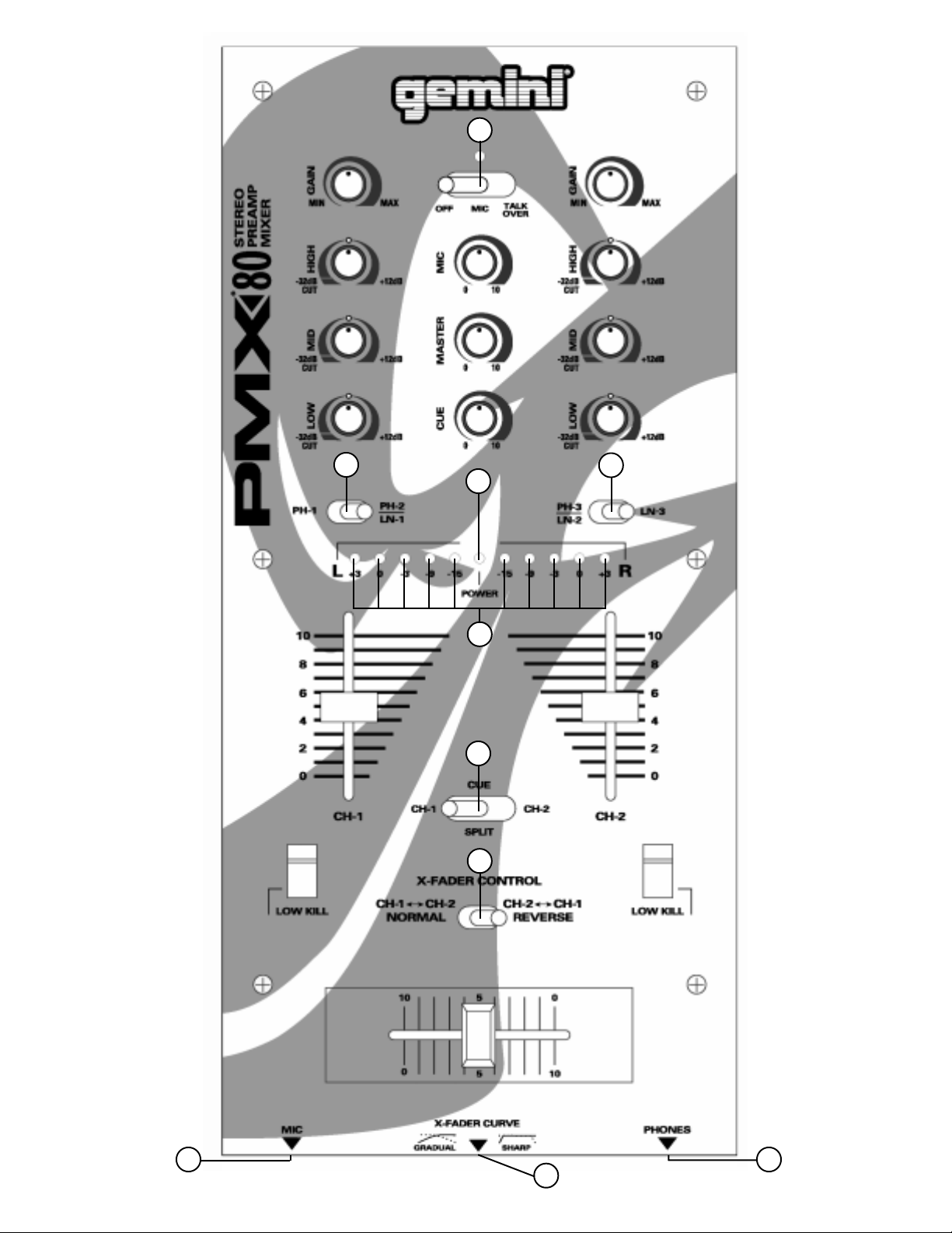
1. POWER ON: Once you have made all the equipment connections to
your mixer, press the POWER (6) switch. The power will turn on and
the POWER LED (23) will glow RED.
2. CHANNEL 1: The GAIN (11), HIGH (12), MID (13), and LOW (14)
controls allow you to fully adjust the selected source. Switch # (15)
allows you to select either the PHONO 1 (5) or the PHONO 2/LINE 1
(4) input. The CHANNEL SLIDE (16) controls the output level of this
channel.
3. CHANNEL 2: The GAIN (29), HIGH (30), MID (31), and LOW (32)
controls allow you to fully adjust the selected source. Switch # (33)
allows you to select either the PHONO 3/LINE 2 (3) or the LINE 3 (2)
input. The CHANNEL SLIDE (34) controls the output level of this
channel.
4. KILLING LOW FREQUENCIES: Y ou can use the Kill Feature on each
channel to remove Low band frequencies to create special effects
and improve your mix. Move the KILL SWITCH (17) down to remove
the low band of Channel 1 from your mix. Move the KILL SWITCH (35)
down to remove the low band of Channel 2 from your mix.
5. CROSSFADER SECTION: The CROSSF ADER (27) allows the mixing of
one source into another. The left side of the CROSSFADER (27) is
CHANNEL 1 and the right side is CHANNEL 2. The CROSSFADER (27)
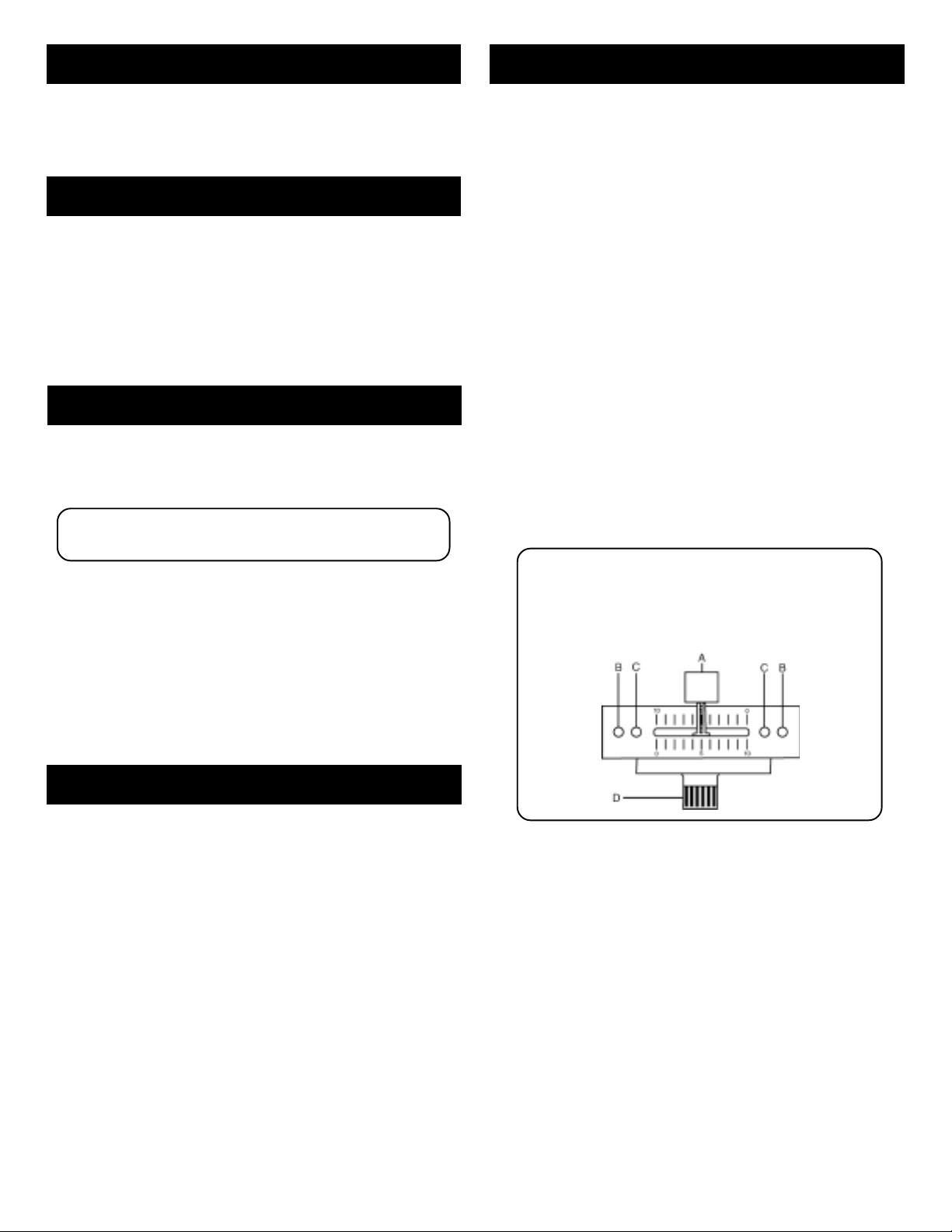
in your unit is removable and if the need arises can be easily replaced.
Crossfader units are available in three varieties. Part # RF-45 (which
is identical to the crossfader supplied with the mixer) has a 45 mm
travel from side to side. Part # RF-30 is available with a 30 mm travel
distance. Also available is the PSF-45 with a special curve designed
for scratch mixing. Just purchase one of these crossfader units from
your Gemini dealer and follow these instructions:
1. Unscrew the outside FADER PLATE SCREWS (B). Do not
touch the INSIDE SCREWS (C).
2. Carefully lift the fader and unplug the CABLE (D).
3. Plug the new fader into the cable and place it back in the
mixer.
4. Screw the fader to the mixer.
Connections
1. Make sure that the POWER (6) switch is in the OFF position. This unit
comes supplied with a 15 volt AC adaptor. Plug the male pin of the
adaptor into the rear panel POWER JACK (7). Then plug the adaptor
into a proper power source.
2. The MASTER OUTPUT (1) jacks are unbalanced and used to connect
to your main amplifier.
3. The DJ MIC (18) input (found on the front panel) accepts a 1/4"
connector and balanced and unbalanced microphones.
4. On the rear panel are 2 stereo PHONO/LINE (3, 4) inputs, 1 stereo
PHONO (5) input and 1 stereo LINE (2) input. The PHONO/LINE
SWITCHES (8, 10) enable you to set the (3, 4) inputs to Phono or Line.
The phono inputs will accept only turntables with a magnetic cartridge.
A GROUND SCREW (9) for you to ground your turntables is located on
the rear panel. The stereo line inputs will accept any line level input
such as a CD player, a cassette player, etc.
5. Headphones can be plugged into the front panel mounted
HEADPHONE (36) jack.
The CROSSFADER CURVE SWITCH (28) allows you to adjust the kind
of curve the crossfader has. When the switch is in the left position,
the curve is gradual and gentle. When the switch is in the right
position, the curve is steep and cutting (perfect for scratching). The
CROSSFADER REVERSE SWITCH (26) allows you to reverse the
crossfader so that CHANNEL 2 is controlled by the left side of the
crossfader and CHANNEL 1 is controlled by the right side of the
crossfader.
NOTE: When the CROSSFADER REVERSE SWITCH
(26) is activated (moved to the right), only the crossfader
reverses. The Channel Slides, Gain, Kill Switches and tonal
controls do not reverse.
6. OUTPUT CONTROL SECTION: The level of the MASTER OUTPUT (1) is
controlled by the MASTER (21) control.
7. TALKOVER SECTION: The purpose of the talkover section is to allow
the program playing to be muted so that the mic can be heard above
the music. The MIC/TALKOVER (19) switch has three settings. When
the MIC/TALKOVER (19) switch is in the left position, the mic and
talkover are both off. When the MIC/TALKOVER (19) switch is in the
center position the mic is on, the MIC INDICATOR will glow, but
talkover is off. When the MIC/TALKOVER (19) switch is in the right
Page 4
Page 5

position, the mic and talkover will be on and the volume of all sources
except the Mic input are lowered by 16 dB. MIC LEVEL (20) controls
the level of the MIC.
8. CUE SECTION: By connecting a set of headphones to the HEADPHONE
(36) jack, you can monitor either channel or both together. Move the
CUE SWITCH (25) to the left to monitor CHANNEL 1. Move the CUE
SWITCH (25) to the right to monitor CHANNEL 2. Move the CUE
SWITCH (25) to the center position to split the signals from each
channel so that CHANNEL 1 will be heard in one earphone and
CHANNEL 2 will be heard in the other earphone. Use the CUE LEVEL
(22) control to adjust the headphone volume without effecting the
overall mix.
9. DISPLAY: The DISPLAY (24) indicates the MASTER output.
Specifications
INPUTS:
DJ Mic..................................................................................1.5 mV 600 Ohm
Phono......................................................................................3mV 47 kOhm
Line...................................................................................150 mV 27 kOhm
OUTPUTS:
Amp.........................................................................0 dB 1V 400 Ohm
Max..............................20V Peak to Peak
GENERAL:
Low (Channels 1 - 2).........................................................+ 12 dB/-32 dB
Mid (Channels 1 - 2)................................................................+ 12 dB/-32 dB
High (Channels 1 - 2).........................................................+ 12 dB/-32 dB
Gain (Channels 1 - 2)..............................................................0 to -20 dB
Frequency Response..........................................20 Hz - 20 kHz +/- 2 dB
Distortion.............................................................................................0.02%
S/N Ratio...........................................................................better than 80 dB
Talkover Attenuation...........................................................................-16 dB
Headphone Impedance.....................................................................16 Ohm
Power Source.................................................................115V/15V AC 7.5 W
230V/15V AC 7.5 W
Dimensions.......................................6.5” x 14” x 3” (165 x 355 x 85 mm)
Weight........................................................................................5 lbs (2.27 kg)
Page 5
Page 6

Einleitung
Bedienung
Wir gratulieren Ihnen zum Kauf eines Gemini PMX-80 Mischpults. Dieses
moderne Mischpult enthält die neuesten Funktionen mit dreijähriger
Garantie, ausscheließlich crossfader und Kanalschieber. Vor
Anwendung dieses Mischpults bitte alle Anweisungen sorgfältig
durchlesen.
Funktionen
• 2 Stereokanäle
• 2 konvertierbare Eingänge für Phonoleitungen/Leitung, Eingänge für 1
Phonoleitungen, Eingänge für 1 Leitungen, Eingang für 1 Mikrophon
• Buchse für DJ Mikrophon (1/4")
• Steuerungen für Tiefton, Mitte, Hochton und Verstärkungsfaktor für
jeden Kanal
• Ausgänge für Master mit regler
• Cue
Vorsichtsmaßnahmen
1. Vor Anwendung dieses Geräts bitte alle Anweisungen sorgfältig
durchlesen.
2. Das Gerät nicht öffnen, um das Risiko elektrischen Schocks zu
vermeiden. Es enthält KEINE VOM ANWENDER ERSETZBAREN TEILE.
Die Wartung darf nur von befähigten Wartungstechnikern
durchgeführt werden.
3. Das Gerät von direktem Sonnenlicht oder einer Wärmequelle wie
Heizkörper oder Ofen aussetzen.
4. Dieses Gerät darf nur mit einem feuchten Tuch gesäubert werden.
Keine Lösungs- oder Reinigungsmittel benutzen.
5. Bei Umzügen sollte das Gerät in seinem ursprünglichen Versandkarton
und Verpackungsmaterial verpackt werden. Dadurch verhindert man,
daß das Gerät während des Transportes beschädigt wird.
6. DIESES GERÄT NICHT REGEN ODER FEUCHTIGKEIT AUSSETZEN.
7. AN DEN REGLERN ODER SCHALTERN KEIN SPRAY-
REINIGUNGSMITTEL ODER SCHMIERMITTEL BENUTZEN.
1. STROM EIN: Nachdem Sie das Gerät am Mischpult angeschlossen
haben, drücken Sie auf die Taste POWER (6). Der Strom wird
eingeschaltet und die rote LEISTUNGS - POWER LED (23) wird
erleuchten.
2. KANAL 1: Die Regelelemente GAIN (11), HIGH (12), MID (13) und
LOW (14) ermöglichen ein vollkommenes Regulieren der
ausgewählten Tonquelle. Schalter # (15) ermöglicht, den Eingang von
PHONO 1 (5) oder PHONO 2/LINE 1 (4) auszuwählen. CHANNEL
SLIDE (16) regelt den Ausgangstonsignal dieses Kanals.
3. KANAL 2: Die Regelelemente GAIN (29), HIGH (30), MID (31) und
LOW (32) ermöglichen ein vollkommenes Regulieren der
ausgewählten Tonquelle. Schalter # (33) ermöglicht, den Eingang von
PHONO 3/LINE 2 (3) oder LINE 3 (2) auszuwählen. CHANNEL SLIDE
(34) regelt den Ausgangstonsignal dieses Kanals.
4. NIEDERFREQUENZEN ABBRECHEN: Sie können die Abbrechfunktion
an jedem Kanal zum Entfernen der Tiefbandfrequenzen benutzen, um
Spezialeffekte zu erzeugen und die Tonmischung zu verbessern. Den
KILL-SCHALTER (17) nach unten zu schieben, um die
Niederfrequenz des Kanal 1 von der Tonmischung zu entfernen. Den
KILL-SCHALTER (35) nach unten schieben, um die Niederfrequenz
des Kanal 2 von der Tonmischung zu entfernen.
5. ÜBERBLENDER: Der Überblender CROSSFADER (27) ermöglicht das
Mischen von Tonquellen. Links des CROSSFADER (27) ist KANAL 1
und die rechte ist KANAL 2. Der CROSSFADER (27) Ihres Geräts kann
entfernt werden und läßt sich bei Bedarf leicht ersetzen. Überblender
sind in drei Größen verfügbar. Teile-Nr. RF-45 (die mit dem Überblender
Ihres Geräts identisch ist) hat eine Seitenverschiebbarkeit von 45 mm.
Gleichfalls ist Teile-Nr. 30 mit einer Verschiebbarkeit von 30 mm
verfügbar. Ebenfalls ist Teile-Nr. PSF-45 mit einer Spezialkrümmung für
Raspelmischen verfügbar. Sie können einen dieser Überblender bei
Ihrem Gemini-Händler beziehen und diese Anweisungen befolgen.
1. Die äußeren SCHRAUBEN DER ÜBERBLENDERPLATTE (B)
losschrauben. Nicht die INNENSCHRAUBEN (C)
losschrauben.
2. Den Überblender vorsichtig anheben und das KABEL (D)
herausziehen.
3. Den neuen Überblender in das Kabel hineinfügen und wieder
in das Mischpult setzen.
4. Den neuen Überblender mit den Schrauben am Mischpult
befestigen.
Anschlüsse
1. Darauf achten, daß der Spannungsschalter POWER (6) in Off-Position
geschaltet ist. Dieses Gerät wird mit einem 15-VWechselstromadapter geliefert. Den Adapterstecker in die
LEISTUNGSBUCHSE - POWER JACK (7) an der Rückwand stecken.
Dann den Adapter an der vorschriftsmäigen Stromquelle anschlieen.
2. Die Buchsen MASTER OUTPUT (1) sind unkompensiert und dienen
zum Anschluß an den Hauptverstärker.
3. Der Eingang DJ MIC (18) (an der Vorderseite) nimmt Anschlüsse mit
Durchmesser von 0,38 mm (1/4"), und balancierte und unbalancierte
Mikrophone auf.
4. An der Rückwand sind jeweils 2 Stereoeingänge PHONO/LINE (3, 4),
1 Stereoeingänge für PHONO (5) und 1 LEITUNG - LINE (2)
angebracht. Die Schalter PHONO/LINE SWITCHES (8, 10) ermöglichen
Ihnen, die Eingänge (3, 4) an Phono oder Line anzuschließen. Die
Phono-Eingänge werden nur Plattenspieler mit einem magnetischem
T onabnehmer aufnehmen. Eine Erdungschraube GROUND SCREW (9)
zur Erdung des Plattenspielers ist an der Rückwand angebracht. Die
Stereo-Leitungseingängen nehmen Geräte wie CD- oder
Kassettenspieler auf.
5. Kopfhörer können an der an der Vorderwand montierten KopfhörerBuchse HEADPHONE (36) eingesteckt werden.
Der CROSSFADER CURVE-SCHAL TER (28) ermöglicht, die jeweilige
Art der Kurve des Überblenders einzustellen. Ist der Schalter nach
links gedreht, verläuft die Kurve sanft und stufenweise. Ist er nach
rechts gedreht, verläuft sie steil und scharf (ideal für
Raspelgeräusch). Der CROSSFADER REVERSE SWITCH (26)
ermöglicht den Rückwärtsgang des Crossfaders Kanal 2 wird nun
kontrolliert durch die linke Seite des Crossfader und Kanal 1 durch die
rechte Seite.
HINWEIS: Ist der CROSSFADER REVERSE-SCHALTER
(26) aktiviert (nach rechts geschoben), läuft nur der
Überblender in Gegenrichtung. Die Kanal-Schieberegler,
Tonstärke- und Überblenderschalter sowie die Tonregler
laufen nicht in Gegenrichtung.
6. AUSGANGSREGELUNG. Der Pegel des MASTER OUTPUT (1)
(Verstärkerausgang) wird mittels der Steuervorrichtung MASTER (21)
gesteuert.
Page 6
Page 7

7. TALKOVER: Durch die Talkover-Funktion wird das abgespielte
Programm gedämpft, um eine Ansage über das Mikrophon hören zu
können. Der Schalter MIC/TALKOVER (19) hat drei Einstellungen.
Wenn der Schalter MIC/TALKOVER (19) in der links Position steht,
sind MIC und Talkover beide ausgeschaltet. Steht der Schalter MIC/
TALKOVER (19) in der mittleren Position, ist MIC eingeschaltet. Der
MIC-Anzeiger ist erleuchtet, jedoch ist Talkover ausgeschaltet. Wenn
der Schalter MIC/TALKOVER (19) in der rechts Position steht, sind
MIC und Talkover eingeschaltet, und Lautstärken aller Tonquellen,
außer des MIC-Eingangs, werden um 16 dB reduziert. MIC LEVEL
(20) reguliert die Tonstärke von MIC.
8. CUE: Indem Sie die Kopfhörer an der KOPFHÖRER-Buchse (36)
anschlieben, können Sie einen oder beide Kanäle zusammen
überwachen. Den CUE-SCHALTER (25) nach links schieben, um
KANAL 1 zu überwachen. Den CUE-SCHALTER (25) nach rechts
schieben, um KANAL 2 zu überwachen. Den CUE-SCHALTER (25)
zur Mitte schieben, um die Signale der beiden Kanäle zu spalten, so
dab man KANAL 1 im einen Kopfhörer und KANAL 2 im anderen
Kopfhörer hören kann. Mit Hilfe des CUE-PEGEL-Reglers (22) kann
die Kopfhörerlautstärke eingestellt werden, ohne dabei die allgemeine
Tonmischung zu beeinträchtigen.
9. ANZEIGE: Die ANZEIGE - DISPLA Y (24) zeigt den REGIEPUL T-
Ausgangspegel an.
Spezifikationen
EINGÄNGE:
DJ-Mikrophon.......................................................................1.5mV 600 Ohm
Phono...................................................................................3 mV, 47 kOhm
Leitung.................................................................................150 mV , 27 kOhm
AUSGÄNGE:
Amp..................................................................................0 dB 1 V 400 Ohm
max............................20 V Spitze-Spitze
ALLGEMEINES:
Tiefenregler (Kanäle 1 - 2)....................................................+ 12 dB/-32 dB
Mittenregler (Kanäle 1 - 2).....................................................+ 12 dB/-32 dB
Höhenregler (Kanäle 1 - 2)......................................................+ 12 dB/-32 dB
Tonstärkenregler (Kanäle 1 - 2)................................................0 bis -20 dB
Frequenzgang......................................................20 Hz - 200 kHz +/- 2 dB
Klirrfaktor..............................................................................................0,02%
Störabstand.......................................................................besser als 80 dB
Talkover-Dämpfung.............................................................................-16 dB
Kopfhörerimpedanz..........................................................................16 Ohm
Stromversorgung.............................................................115V/15V AC 7.5W
230V/15V AC 7.5W
Abmessungen................................................................165 x 355 x 85 mm
Gewicht................................................................................................2.27 kg
Page 7
Page 8

Introducción
Funcionamiento
Felicitaciones por su compra del mezclador PMX-80 de Gemini. Este
mezclador de la más avanzada tecnología está dotado de características
ultramodernas y está respaldado por una garantía de tres años, salvo el
crossfader y los mandos corredizos de canal. Antes de usarlo, le
recomendamos leer cuidadosamente todas las instrucciones.
Características
• 2 canales estereofónicos
• 2 entradas fono/línea convertibles, 1 entrada de fono, 1 entrada de
línea, y 1 entrada para micrófono
• Jack para micrófono DJ tipo 1/4 de pulgada
• Controles de tonos Bajos, Medios y Agudos y de Ganancia en cada
canal
• Salidas para maestras con la llave corrediza maestra
• Seccion de referencia
Precauciones
1. Deberán leerse todas las instrucciones de operación antes de usar el
equipo.
2. Para reducir el riesgo de shock eléctrico, no abra esta unidad. No
contiene PIEZAS REEMPLAZABLES POR EL USUARIO. Por favor,
refiera el servicio a un técnico de servicio calificado.
3. No exponga la unidad a la luz solar directa ni a una fuente de calor,
por ejemplo, un radiador o estufa.
4. Esta unidad sólo deberá limpiarse con un paño húmedo. Evite el uso
de disolventes u otros detergentes de limpieza.
5. Para mover este equipo, colóquelo en la caja y empaque original, a fin
de reducir el riesgo de daños durante el transporte.
6. NO DEJE ESTA UNIDAD EXPUEST A A LLUVIA O HUMEDAD.
7. NO USE LIMPIADORES DE ROCÍO O LUBRICANTES EN CUALESQUIER
CONTROLES O INTERRUPTORES.
Conexiones
1. ENCENDIDO: Una vez que haya efectuado todas las conexiones de
los equipos a su mezclador, oprima el INTERRUPT OR DE ENERGÍA -
POWER (6). Se encenderá la unidad y el LED ROJO de ENERGÍA POWER LED (23).
2. CANAL 1: Los mandos de GAIN (11) (ganancia), HIGH (12) (alto), MID
(13) (mediano) y LOW (14) (bajo) le permiten arreglar plenamente la
fuente seleccionada. El interruptor # (15) le permite seleccionar la
entrada PHONO 1 (5) o PHONO 2/LINE 1 (4). El CHANNEL SLIDE (16)
(cursor corredizo de canal) controla el volumen de salida de este
canal.
3. CANAL 2: Los mandos de GAIN (29) (ganancia), HIGH (30) (alto), MID
(31) (mediano) y LOW (32) (bajo) le permiten arreglar plenamente la
fuente seleccionada. El interruptor # (33) le permite seleccionar la
entrada PHONO 3/LINE 2 (3), o LINE 3 (2). El CHANNEL SLIDE (34)
(cursor corredizo de canal) controla el volumen de salida de este
canal.
4. KILLING LOW FREQUENCIES: Se puede utilizar la función Kill en cada
canal para eliminar las bajas frecuencias de banda para crear efectos
especiales y para mejorar la mezcla. Mueva el KILL SWITCH (17)
hacia abajo para eliminar la baja frecuencia del Canal 1 de su mezcla.
Mueva el KILL SWITCH (35) hacia abajo para eliminar la baja
frecuencia del Canal 2 de su mezcla.
5. SECCIÓN DE ATENUADOR DE TRANSFERENCIA: El A TENUADOR DE
TRANSFERENCIA - CROSSFADER (27) le permite mezclar una fuente
en otra. El lado izquierdo del CROSSFADER (27) corresponde al
CANAL 1 y el lado derecho corresponde al CANAL 2. El
CROSSFADER (27) de su aparato es removible y, en caso de
necesidad, su reemplazo es fácil. Se ofrecen unidades de atenuador
de transferencia de tres tamaños. La Pieza Nº RF-45 (idéntico al
atenuador de transferencia suministrado con su unidad) tiene un
recorrido de 45mm de un lado a otro. También se ofrece la pieza nº
RF-30, que tiene un recorrido de 30mm. También se ofrece la pieza
PSF-45 con curva especial diseñada para la mezcla del efecto de
frotamiento. Simplemente compre cualquiera de estas unidades de
atenuador de transferencia de su distribuidor Gemini y siga las
instrucciones siguientes:
1. Destornille los TORNILLOS EXTERIORES de la PLACA DEL
ATENUADOR (B). No toque LOS TORNILLOS INTERNOS
(C).
2. Levante cuidadosamente el atenuador y desenchufe el
CABLE (D).
3. Conecte el nuevo atenuador al cable y póngalo de nuevo
dentro del mezclador.
4. Atornille el atenuador en el mezclador.
1. Cerciórese de que el interruptor de ENERGÍA - POWER (6) esté en la
posición off (apagada). Esta unidad se suministra con un adaptador
CA de 15 voltios. Enchufe la clavija macho del adaptador en el JACK
DE ENERGÍA - POWER JACK (7) del panel trasero. Luego enchufe el
adaptador en una fuente de energía apropiada.
2. Los jacks MASTER OUTPUT (1) (amplificador de salida) no son
equilibrados y se usan para la conexión al amplificador principal.
3. La entrada DJ MIC (18) (que se encuentra en el panel delantero)
acepta conector de 1/4 de pulgada y micrófonos equilibrados y no
equilibrados.
4. En el panel trasero hay 2 entradas estereofónicas FONÓGRAFO/
LÍNEA - PHONO/LINE (3, 4), 1 entrada estereofónica de FONÓGRAFO
- PHONO (5) y 1 entrada estereofónica de LÍNEA - LINE (2). Los
conmutadores PHONO/LINE SWITCHES (8, 10) le permiten arreglar
las entradas (3, 4) a Phono o Line (fonográfico o línea). Las entradas
fonográficas solamente aceptarán giradiscos con cartucha
magnética. Un GROUND SCREW (9) para poner el giradiscos a tierra
se encuentra en el panel trasero. Las entradas de línea
estereofónicas aceptarán cualquier entrada de nivel de línea tal como
tocadisco de discos compactos o casetera, etc.
5. Los audífonos se enchufan en el jack de HEADPHONE (36)
(audífonos) montado en el panel delantero.
El CROSSF ADER CUR VE SWITCH (28) le permite ajustar la curva del
crossfader. Con el interruptor en la posición de izquierda, la curva es
progresiva y suave. Con el interruptor en la posición de derecha, la
curva tiene pendiente fuerte y cortante (perfecto para realizar el
“scratching”). El CROSSFADER REVERSE SWITCH (26) le permite
invertir el crossfader; asi el canal 2 será mandado por el lado
izquierdo del crossfader y el canal 1 lo será por el lado derecho del
crossfader.
NOTA: Cuando se activa el CROSSFADER REVERSE
SWITCH (26) (posicionado a la derecha), solamente se
produce la inversión del crossfader. No se produce en los
cursores corredizos de canales, en el Gain, en los
interruptores Kill y en los mandos de tonalidad.
Page 8
Page 9

6. SECCIÓN DE CONTROL DE LA SALIDA: El nivel de la salida del
amplificador MASTER OUTPUT (1) se controla con la llave corrediza
maestra MASTER (21).
7. SECCIÓN TALKOVER: El propósito de la sección talkover es de permitir
al programa de ponerse sordina para que se pueda oír el mensaje del
micrófono por encima de la música. El interruptor MIC/TALKOVER
(19) tiene tres arreglos. Cuando el interruptor MIC/TALKOVER (19)
ocupa la posición izquierda, el MIC y la función talkover están ambos
apagados. Cuando el interruptor MIC/TALKOVER (19) ocupa la
posición central, el MIC está activado, el INDICADOR MIC se prenderá
pero la función talkover está apagada. Cuando el interruptor MIC/
TALKOVER (19) ocupa la posición derecha, el MIC y la función
talkover estarán prendidos y el volumen de todas las fuentes salvo las
entradas Mic serán reducidas por 16 dB. El MIC LEVEL (20) controla
el volumen del micrófono.
8. SECCIÓN CUE (DE REFERENCIA): Al conectar audífonos al jack de
HEADPHONE (36), se puede monitorear el canal 1, el canal 2 o ambos
a la vez. Mueva el CUE SWITCH (25) a la izquierda para monitorear el
CANAL 1. Mueva el CUE SWITCH (25) a la derecha para monitorear el
CANAL 2. Mueva el CUE SWITCH (25) a la posición central para
dividir las señales de cada canal para que se oiga el CANAL 1 en un
audífono y el CANAL 2 en el otro. Utilice el mando del CUE LEVEL (22)
para ajustar el volumen del audífono sin afectar la mezcla global.
9. PRESENTACIÓN: La PRESENTACIÓN - DISPLAY (24) indica los niveles
de salida del control MAESTRO.
Especificaciones técnicas
ENTRADAS:
Micrófono DJ......................................................................1.5 mV 600 Ohm
Fonógrafo........................................................................3 mV 47 Kohmios
Línea..............................................................................150 mV 27 Kohmios
SALIDAS:
Amplificador................................................................0 dB 1 V 400 ohmios
Máx....................................20 V pico-pico
GENERALES:
Bajos (canales 1 - 2)........................................................+ 12 dB/-32 dB
Medianos (canales 1 - 2)....................................................+ 12 dB/-32 dB
Altos (canales 1 - 2)............................................................+ 12 dB/-32 dB
Ganancia (canales 1 - 2)..........................................................de 0 a -20 dB
Respuesta de frecuencia.........................................20 Hz - 20 kHz +/- 2dB
Distorsión..............................................................................................0,02%
Relación señal/ruido.........................................................superior a 80 dB
Atenuación talkover..........................................................................-16 dB
Impedancia del audífono.............................................................16 ohmios
Fuente de energía........................................................115V/15V AC 7.5 W
230V/15V AC 7.5 W
Dimensiones....................................................................165 x 355 x 85 mm
Peso........................................................................................................2.27
k g
Page 9
Page 10

Introduction
Fonctionnement
Nos félicitations à l’occasion de votre achat du mélangeur PMX-80 de
Gemini. Ce mélangeur très moderne inclut les caractéristiques
technologiques les plus récentes et il est accompagné d’une garantie de
trois ans, à l’exclusion du crossfader et des curseurs de canal. Avant de
vous en servir, lisez attentivement toutes les instructions ci-après.
Caractéristiques
• 2 canaux stéreo
• 2 entrées phono/ligne convertibles, 1 entrée phono, 1 entrée ligne et 1
entrée micro
• Jack for micro d’animateur à raccord 1/4 de pouce
• Basse, médiane, aigu et réglage du gain sur chaque canal
• Sorties principales et la commande master
• Cue
Avertissements
1. On devrait lire toutes les consignes d’exploitation avant d’utiliser ce
matériel.
2. Afin de réduire le risque de choc électrique, n’ouvrez pas l’appareil. Il
n’y a pas de PIÈCES REMPLAÇABLES À L’INTÉRIEUR. V euillez
soumettre l’entretien/la réparation à un technicien qualifié.
3. Ne pas exposer cet appareil aux rayons du soleil direct ou à une
source de chaleur telle qu’un radiateur ou un poêle.
4. Cet appareil devrait être nettoyé seulement avec un chiffon humide.
Evitez les solvants et autres détergents de nettoyage.
5. Quand on déplace ce matériel, il devrait être mis dans son carton et
son emballage d’origine. Ceci réduira le risque de dégâts pendant le
transport.
6. NE PAS EXPOSER CET APPAREIL À LA PLUIE OU À L ’HUMIDITÉ.
7. N’UTILISEZ PAS DE PRODUIT DE NETTOY AGE A VEC V APORISATEUR
OU LUBRIFIANT SUR AUCUN DES BOUTONS OU DES
INTERRUPTEURS.
1. POWER ON (MISE SOUS TENSION): Dès que tous les branchements
sont effectués à votre mélangeur, appuyez sur le POWER (6) (touche
de mise sous tension). L’appareil sera en fonction et la DEL - POWER
LED (23) ROUGE s’allumera.
2. CANAL 1: Les commandes GAIN (11), HIGH (12) (élevé), MID (13)
(moyen) et LOW (14) (bas) vous permettent de régler entièrement la
source choisie. Le commutateur # (15) vous permet de choisir l’entrée
PHONO 1 (5) ou PHONO 2/LINE 1 (4). Le CHANNEL SLIDE (16)
(curseur de canal) commande la sortie de ce canal.
3. CANAL 2: Les commandes GAIN (29), HIGH (30) (élevé), MID (31)
(moyen) et LOW (32) (bas) vous permettent de régler entièrement la
source choisie. Le commutateur # (33) vous permet de choisir l’entrée
PHONO 3/LINE 2 (3) ou LINE 3 (2). Le CHANNEL SLIDE (34) (curseur
de canal) commande la sortie de ce canal.
4. SUPPRESSION BASSES FRÉQUENCES: Vous pouvez vous servir de la
fonction Kill (suppression) sur chaque canal pour supprimer les
basses fréquences afin de créer des effets spéciaux et afin
d’améliorer le mélange. Déplacez le KILL SWITCH (17) en bas pour
supprimer les basses fréquences du Canal 1 de votre mélange.
Déplacez le KILL SWITCH (35) en bas pour supprimer les basses
fréquences du Canal 2 de votre mélange.
5. SECTION CROSSFADER: Le CROSSF ADER (27) (l’atténuateur croisé)
permet le mélange d’une source avec une autre. Le côté gauche du
CROSSFADER (27) est le CANAL 1 et le côté droit est le CANAL 2. Le
CROSSFADER (27) de votre appareil est amovible et s’il le faut, il est
facilement remplacé. Des appareils crossfader sont disponibles en
trois genres. La pièce no RF-45 (identique à celui fourni avec le
mélangeur) a une course de 45 mm d’un côté à l’autre. La pièce no.
RF-30 est disponible avec une course de 30 mm. Puis, il y a la pièce
no. PSF-45 avec courbe spéciale conçue pour le mélange de l’effet de
“frottement”. Il suffit d’acquérir un de ces genres auprès de votre
concessionnaire Gemini et de suivre les instructions suivantes:
1. Dévissez les VIS externes DE LA PLAQUE DE
L’A TTÉNUA TEUR (B). Ne touchez pas aux VISSES INTERNES
(C).
2. Soulevez soigneusement l’atténuateur et débranchez le
CÂBLE (D).
3. Branchez le nouvel atténuateur au câble et replacez-le
dans le mélangeur.
4. Vissez l’atténuateur au mélangeur.
Connexions
1. Le commutateur POWER (6) (puissance) doit occuper la position OFF
(hors tension). Cet appareil est doté d’un adaptateur de 15 Vca.
Raccordez la broche mâle de l’adaptateur à la prise - POWER JACK
(7) sur le panneau arrière. Puis, raccordez l’adaptateur à une source
électrique appropriée.
2. Les jacks MASTER OUTPUT (1) (sortie amplificateur) ne sont pas
équilibrés et s’utilisent pour brancher l’amplificateur principal.
3. L’entrée DJ MIC (18) (retrouvée sur le panneau avant) accepte un
connecteur de 1/4 de pouce et des microphones équilibrés et non
équilibrés.
4. Sur le panneau arrière, il y a 2 entrées stéréo PHONO/LINE (3, 4), 1
entrée PHONO (5) stéréo et 1 entrée LINE (2) stéréo. Les PHONO/
LINE SWITCHES (8, 10) (commutateurs phono/ligne) vous permettent
de régler les entrées (3, 4) sur Phono ou Ligne. Les entrées phono
n’acceptent que des tables tournantes avec cartouche magnétique.
Une GROUND SCREW (9) (vis de terre) pour la mise à la masse des
tables tournantes est située sur le panneau arrière. Les entrées de
ligne stéréo accepteront n’importe quelle entrée de ligne telle que CD
player, cassette player, etc.
5. Les écouteurs peuvent être branchés au jack HEADPHONE (36) que
l’on retrouve sur le panneau avant.
Le CROSSFADER CURVE SWITCH (28) vous permet d’ajuster la
courbe du crossfader. Lorsque l’interrupteur occupe la position de
gauche, la courbe est progressive et modérée. Lorsque l’interrupteur
occupe la position de droite, la courbe est raide et coupante (parfaite
pour le “scratching”). Le CROSSFADER REVERSE SWITCH (26) vous
permet de renverser le crossfader; ainsi le canal 2 ser commandé par
le côté gauche du crossfader et le canal 1 par le côté droit du
crossfader.
REMARQUE: Lorsque le CROSSFADER REVERSE
SWITCH (26) est activé (déplacé à droite), seul le
crossfader sera renversé. Les curseurs coulissants des
canaux, le gain, les interrupteurs Kill et les commandes de
tonalité ne sont pas renversés.
6. SECTION OUTPUT CONTROL: Le niveau de MASTER OUTPUT (1) est
commandé par la commande MASTER (21).
Page 10
Page 11

7. SECTION “TALKOVER”: Le propos de cette section est de permettre
au programme en marche d’être assourdi de sorte que le message
transmis par le micro puisse être entendu par-dessus la musique. Le
MIC/TALKOVER (19) comporte trois réglages. Lorsque le MIC/MIC/
TALKOVER (19) occupe la position de gauche, le MIC et la fonction
talkover sont au repos. Lorsque le MIC/TALKOVER (19) occupe la
position centrale, le MIC est sous tension, le MIC INDICATOR
s’allumera mais la fonction talkover est au repos. Lorsque le MIC/
TALKOVER (19) occupe la position droite, le MIC et la fonction talkover
seront activés et le volume de toutes les sources, sauf les entrées
mic, sera réduit de 16 dB. Le MIC LEVEL (20) commande le volume du
microphone.
8. SECTION “CUE”: En branchant des écouteurs au jack de HEADPHONE
(36), vous pouvez suivre le canal 1, le canal 2 ou les deux à la fois.
Déplacez le CUE SWITCH (25) à gauche pour suivre le CANAL 1.
Déplacez le CUE SWITCH (25) à droite pour suivre le CANAL 2.
Déplacez le CUE SWITCH (25) vers le centre pour diviser les signaux
de chaque canal de sorte que le CANAL 1 puisse être entendu dans
un écouteur et le CANAL 2 dans l’autre. Servez-vous de la commande
CUE LEVEL (22) pour ajuster le volume des écouteurs sans affecter
le mélange global.
9. DISPLAY (Affichage): L’AFFICHAGE - DISPLAY (24) indique les
volumes de sortie du MASTER.
Caractéristiques techniques
ENTRÉES:
DJ Mic..................................................................................1.5mV 600 Ohm
Phono......................................................................................3 mV 47 kOhm
Ligne......................................................................................150 mV 27 kOhm
SORTIES:
Amplificateur...............................................................0 dB 1V 400 Ohm
GÉNÉRALITÉS:
Basses (canaux 1 - 2)...................................................+ 12 dB/-32 dB
Moyenne (canaux 1 - 2)..................................................+ 12 dB/-32 dB
Hautes (canaux 1 - 2)........................................................+ 12 dB/-32 dB
Gain (canaux 1 - 2)..................................................................de 0 à - 20 dB
Réponse de fréquence.........................................20 Hz - 20 kHz+/- 2 dB
Distorsion..............................................................................................0,02%
Rapport signal/bruit..........................................................supérieur à 80 dB
Atténuation talkover...............................................................................-16 dB
Impédance écouteur..........................................................................16 ohm
Source d’énergie..........................................................115V/15V AC 7.5 W
Dimensions......................................................................165 x 355 x 85 mm
Poids..................................................................................................2.27 kg
maxi........................................20V crête-crête
230V/15V AC 7.5 W
Page 11
Page 12

Introduzione
Funzionamento
Complimenti per l’acquisto di questo miscelatore PMX-80 Gemini. Questo
miscelatore d’avanguardia ha incorporato i componenti più recenti e offre
una garanzia di tre anni, escluso il crossfader ed i cursori canale. Prima
dell’uso leggere attentamente queste istruzioni.
Caratteristiche
• 2 canali stereo
• 2 ingressi Phono/Linea convertibile, 1 per phono, 1 per linee ed 1 per Mic
• Jack per microfono DJ per connettore 1/4"
• Controlli per i toni bassi, medi e acuti e per il guadagno in
amplificazione
• Uscite master con la levetta
• Sezione preascolto
Precauzioni
1. Leggere attentamente queste istruzioni prima di usare questo
apparecchio.
2. Per evitare scosse elettriche non aprire l’apparecchio. INTERNAMENTE
NON CI SONO COMPONENTI SOSTITUIBILI DALL’UTENTE. Per le
riparazioni rivolgersi solo a personale qualificato.
3. Non esporre l’apparecchio alla luce diretta del sole o metterlo vicino a
fonti di calore come caloriferi o stufe.
4. Pulire questo apparecchio solo con un panno inumidito. Evitare di
usare solventi o altri detergenti.
5. Per trasportare questo apparecchio si consiglia di rimetterlo nella
scatola e usare l’imballaggio originale. Questo eviterà di danneggiarlo
durante il trasporto.
6. EVITARE DI ESPORRE L’APP ARECCHIO ALLA PIOGGIA O ALL ’UMIDIT A ’.
7. NON USARE DETERGENTI SPRAY O LUBRIFICANTI SU QUALSIASI
CONTROLLO O INTERRUTTORE.
1. ACCENSIONE: Dopo che sono stati eseguiti tutti i collegamenti degli
apparecchi con il miscelatore, premere POWER (6). Verrà attivata
l’alimentazione e l’INDICAT ORE POWER- POWER LED (23) diventerà
ROSSO.
2. CANALE 1: I comandi GAIN (11), HIGH (12), MID (13) e LOW (14)
permettono di regolare correttamente la sorgente selezionata.
L’interruttore # (15) permette di selezionare gli ingressi PHONO 1 (5) o
PHONO 2/LINE 1 (4). Il CURSORE CANALE - CHANNEL SLIDE (16)
controlla il livello d’uscita di questo canale.
3. CANALE 2: I controlli GAIN (29), HIGH (30), MID (31) e LOW (32)
permettono di regolare correttamente la sorgente selezionata.
L’interruttore # (33) permette di selezionare l’ingresso PHONO 3/LINE 2
(3) o LINE 3 (2). Il CURSORE CANALE - CHANNEL SLIDE (34)
controlla il livello d’uscita di questo canale.
4. SOPPRESSIONE DEI BASSE FREQUENZE: Si può usare la funzione Kill
(Soppressione) in ogni canale per rimuovere i basse frequenze de
banda per creare effetti speciali e per migliorare la miscelazione.
Muovere il KILL SWITCH (17) abbasso per rimuovere la bassa
frequenza (Low) del Canale 1 della miscelazione. Muovere il KILL
SWITCH (35) abbasso per rimuovere la bassa frequenza (Low) del
Canale 2 della miscelazione.
5. SEZIONE CROSSFADER (Dissolvenza incrociata): Il CROSSF ADER
(27) permette di miscelare una sorgente con un’altra. La parte sinistra
del CROSSFADER (27) corrisponde al CANALE 1 e quella destra
corrisponde al CANALE 2. Il CROSSFADER (27) di questo miscelatore
è rimovibile e se necessario può essere facilmente sostituito. Il
crossfader è disponibile in tre formati. Il componente # RF-45 (che è
identico al crossfader fornito con questo miscelatore) ha un percorso
di 45mm da lato a lato. E’ anche disponibile il componente RF-30 con un
percorso di 30 mm e il componente PSF-45 con una curva speciale
studiata per la miscelazione scratch. Acquistare uno di questi
crossfader dal rivenditore Gemini e seguire queste istruzioni:
1. Svitare le VITI esterne della PIASTRA DEL FADER (B). Non
toccare le VITI INTERNE (C).
2. Sollevare con cura il fader e staccare il CAVO (D).
3. Inserire il nuovo fader nel cavo e rimetterlo nel miscelatore.
4. Avvitare il fader nel miscelatore.
Collegamenti
1. Assicurarsi che il POWER (6) sia su off. Questo apparecchio viene
fornito con un adattatore di 15 volt CA. Inserire la spina maschio
dell’adattatore nel POWER JACK (7) posto sul pannello posteriore.
Inserire poi l’adattatore nell’appropriata presa di corrente.
2. I jacks MASTER OUTPUT (1) non sono bilanciati e sono usati per
collegare l’amplificatore principale.
3. L’ingresso DJ MIC (18) (posto sul pannello anteriore) accetta un
connettore da 1/4" e microfoni bilanciati e non bilanciati.
4. Sul pannello posteriore ci sono 2 ingressi PHONO/LINE (3, 4), 1
ingresso stereo PHONO (5) e 1 ingresso LINEE STEREO - LINE (2). Gli
interruttori PHONO/LINE SWITCHES (8, 10) permettono di impostare gli
ingressi (3, 4) su Phono o Line. Gli ingressi phono accetteranno
solamente i giradischi con la cartuccia magnetica. Sul pannello
posteriore si trova una vite di MESSA A TERRA - GROUND SCREW
(9) per la messa a terra dei giradischi. Gli ingressi della linea stereo
accettano qualsiasi ingresso di livello di linea come ad esempio un
lettore di CD, registratori a cassette ecc.
5. Le cuffie possono essere inserite nel jack HEADPHONE (36) che si
trova sul pannello anteriore.
Il CROSSFADER CUR VE SWITCH (28) permette di regolare la curva
del crossfader. Quando l’interruptore è impostato sulla posizione
sinistra, la curva è progressiva e moderata. Quando l’interruptore è
impostato sulla posizione destra, la curva è erta e tagliente (perfetto
per il “scratching”). Con il CROSSFADER REVERSE SWITCH (26) è
possibile rovesclare il crossfader cossichè il canale 2 sarà controllato
per il lato sinistro del crossfader ed il canale 1 per il lato destro.
NOTA: Quando il CROSSFADER REVERSE SWITCH (26) si
attiva (spostato alla destra), solo il crossfader funziona in
senso inverso. La marcia in senso inverso non si fa per i
cursori scorrevole canale, il gain, gli interruttori
Soppressione ed i controlli della tonalità.
6. SEZIONE CONTROLLO OUTPUT : Il livello del MASTER OUTPUT (1) è
controllato con la levetta scorrevole MASTER (21).
Page 12
Page 13

7. SEZIONE TALKOVER: Questa funzione permette di attenuare la
riproduzione del programma in modo che si possa sentire il microfono
sopra la musica. L’interruttore MIC/TALKOVER (19) ha tre
impostazioni. Quando l’interruttore MIC/TALKOVER (19) è impostato
sulla posizione sinistra, il MIC e il talkover sono entrambi spenti.
Quando l’interruttore MIC/TALKOVER (19) è impostato sulla posizione
centrale il MIC è acceso. L’INDICA T ORE MIC si illuminerà, ma il talkover
è spento. Quando l’interruttore MIC/TALKOVER (19) è impostato sulla
posizione destra, il MIC e il talkover saranno accessi e il volume delle
sorgenti ad eccezione degli ingressi Mic verranno abbassati a 16 dB. Il
MIC LEVEL (20) controlla il livello del microfono.
8. Sezione CUE: Collegando un set di cuffie al jack HEADPHONE (36), é
possibile controllare sia il canale 1 sia il canale 2 o entrambi. Far
scorrere il CUE SWITCH (25) sulla sinistra per controllare il CANALE
1. Far scorrera il CUE SWITCH (25) sulla destra per controllare il
CANALE 2. Far scorrere il CUE SWITCH sulla posizione centrale per
dividere i segnali di ogni canale in modo che si possa sentire il Canale
1 in una cuffia ed il CANALE 2 in l’altra. Usare il controllo CUE LEVEL
(22) per regolare il volume della cuffia senza influenzare la
miscellazione globale.
9. DISPLAY: Il DISPLAY (24) indica i livelli di uscita di destra e di sinistra
del MASTER.
Specifiche Tecniche
INGRESSI:
Ingresso microfono DJ.........................................................1.5mV 600 Ohm
Phono..........................................................................................3mV 47Kohm
Linea...................................................................................150 mV 27Kohm
USCITA:
Amp...................................................................................0 dB 1V 400ohm
GENERALE:
Low (Canale 1 - 2).................................................................+ 12 dB/-32 dB
Mid (Canale 1 - 2)................................................................+ 12 dB/-32 dB
High (Canale 1 - 2)...............................................................+ 12 dB/-32 dB
Regolatore di amplificazione (Canale 1 - 2).............................da 0 a -20dB
Risposta in frequenza.................................................20Hz - 20KHz +/- 2dB
Distorsione..............................................................................................0,02%
Rapporto segnale/disturbo (S/N)...........................................migliore di 80 dB
Livello talkover.....................................................................................-16dB
Impedenza cuffia................................................................................16ohm
Alimentazione..................................................................115V/15V AC 7.5 W
Dimensioni........................................................................165 x 355 x 85 mm
Peso....................................................................................................2.27 kg
Max.....................................20V picco a picco
230V/15V AC 7.5 W
Page 13
Page 14

In the USA: If you experience problems with this unit,
call 1-732-738-9003 for Gemini Customer Service.
Do not attempt to return this equipment to your dealer.
Parts of the design of this product may be protected by worldwide patents.
Information in this manual is subject to change without notice and does not
represent a commitment on the part of the vendor. Gemini Sound Products Corp.
shall not be liable for any loss or damage whatsoever arising from the use of
information or any error contained in this manual.
No part of this manual may be reproduced, stored in a retrieval system or
transmitted, in any form or by any means, electronic, electrical, mechanical, optical,
chemical, including photocopying and recording, for any purpose without the
express written permission of Gemini Sound Products Corp.
It is recommended that all maintenance and service on this product is performed
by Gemini Sound Products Corp. or its authorized agents.
Gemini Sound Products Corp. will not accept liability for loss or damage caused
by maintenance or repair performed by unauthorized personnel.
Worldwide Headquarters • 120 Clover Place, Edison, NJ 08818 • USA
T el: (732) 738-9003 • Fax: (732) 738-9006
France • G.S.L. France • 11, A venue Leon Harmel, Z.I. Antony, 92160 Antony, France
Tel: + 33 (0) 1 55 59 04 70 • Fax: + 33 (0) 1 55 59 04 80
Germany • Gemini Sound Products GmbH • Ottostrasse 6, 85757 Karlsfeld, Germany
Tel: 08131 - 39171-0 • Fax: 08131 - 39171-9
UK • Gemini Sound Products • Unit C4 Hazleton Industrial Estate, Waterlooville, UK P08 9JU
Tel: 087 087 00880 • Fax: 087 087 00990
Spain • Gemini Sound Products S.A. • Mino, 112, Nave 1, 08223 Terrassa, Barcelona, Spain
Tel: 011-34-93-736-34-00 • Fax: 011-34-93-736-34-01
© Gemini Sound Products Corp. 2001 All Rights Reserved
Page 14
 Loading...