

Page 1
Professional 2 Channel Stereo Mixer
Professioneller 2-Kanal Stereo-Mixer
Mezclador Estereo de 2 Canales Profesional
Mixer Stereo 2 Voies Professionnel
OPERATIONS MANUAL
BEDIENUNGSHANDBUCH
MANUAL DEL OPERADOR
MANUEL D’INSTRUCTIONS
Page 2
MULTI LANGUAGE INSTRUCTIONS
ENGLISH........................................................................................................................................................................................................................PAGE 4
DEUTSCH......................................................................................................................................................................................................................PAGE 7
ESPAÑOL.......................................................................................................................................................................................................................PAGE 10
FRANCAIS......................................................................................................................................................................................................................PAGE 13
PLEASE READ BEFORE USING APPLIANCE, IMPORTANT WARNING & SAFETY INSTRUCTIONS!
CAUTION
RISK OF ELECTRICAL SHOCK DO NOT OPEN!
CAUTION: This product satisfies FCC regulations when shielded cables and connec-
tors are used to connect the unit to other equipment. To prevent electromagnetic
interference with electric appliances such as radios and televisions, use shielded
cables and connectors for connections.
The exclamation point within an equilateral triangle is intended to alert the user to
the presence of important operating and maintenance (servicing) instructions in
the literature accompanying the appliance.
The lightening flash with arrowhead symbol, within an equilateral triangle, is
intended to alert the user to the presence of uninsulated “dangerous voltage” within the product’s enclosure that may be of sufficient magnitude to constitute a risk
of electric shock to persons.
READ INSTRUCTIONS: All the safety and operating instructions should be read
before the product is operated.
RETAIN INSTRUCTIONS: The safety and operating instructions should be retained
for future reference.
HEED WARNINGS: All warnings on the product and in the operating instructions
should be adhered to.
FOLLOW INSTRUCTIONS: All operating and use instructions should be followed.
CLEANING: The product should be cleaned only with a polishing cloth or a soft dry
cloth. Never clean with furniture wax, benzine, insecticides or other volatile liquids
since they may corrode the cabinet.
ATTACHMENTS: Do not use attachments not recommended by the product manu-
acturer as they may cause hazards.
WATER AND MOISTURE: Do not use this product near water, for example, near a
bathtub, wash bowl, kitchen sink, or laundry tub; in a wet basement; or near a
swimming pool; and the like.
ACCESSORIES: Do not place this product on an unstable cart, stand, tripod, brack-
et, or table. The product may fall, causing serious injury to a child or adult, and
serious damage to the product. Use only with a cart, stand, tripod, bracket, or table
recommended by the manufacturer, or sold with the product. Any mounting of the
product should follow the manufacturer’s instructions, and should use a mounting
accessory recommended by the manufacturer.
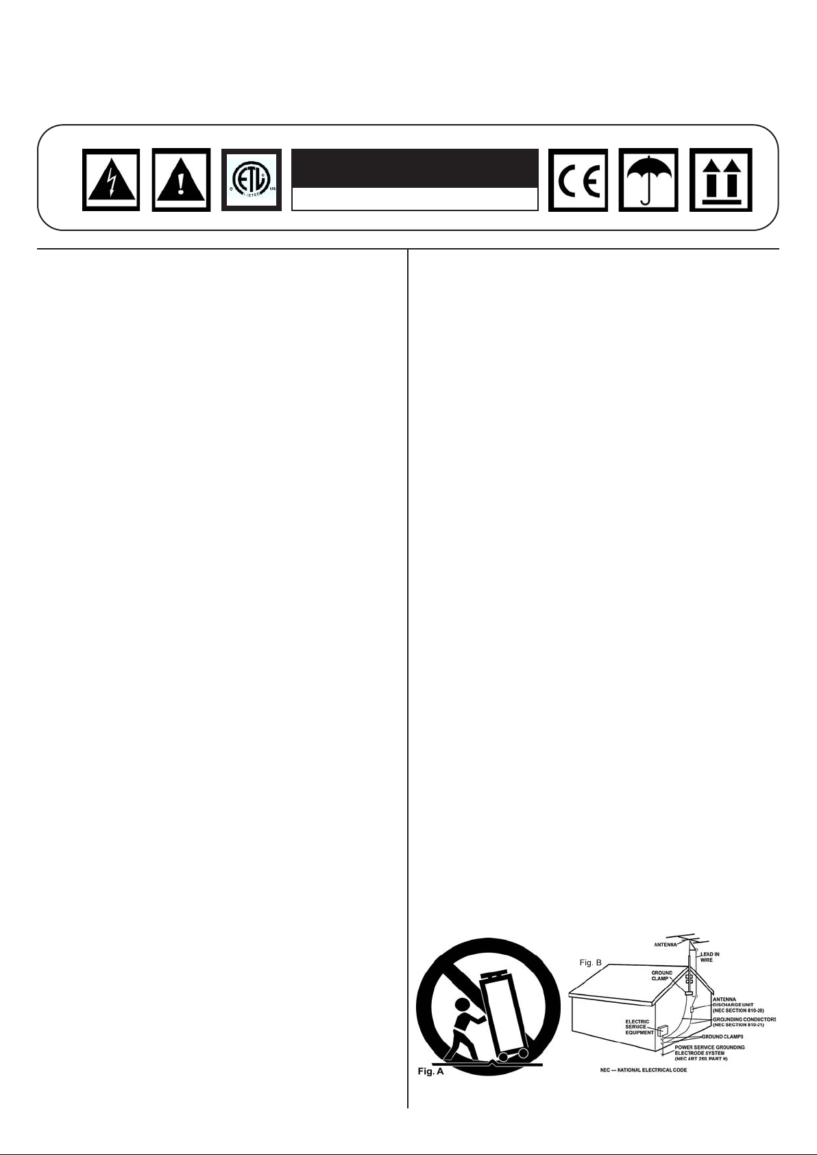
CART: A product and cart combination should be moved with care. Quick stops,
excessive force, and uneven surfaces may cause the product and cart combination to overturn. See Figure A.
VENTILATION: Slots and openings in the cabinet are provided for ventilation and to
ensure reliable operation of the product and to protect it from overheating, and
these openings must not be blocked or covered. The openings should never be
blocked by placing the product on a bed, sofa, rug, or other similar surface. This
product should not be placed in a built-in installation such as a bookcase or rack
unless proper ventilation is provided or the manufacturer’s instructions have been
adhered to.
POWER SOURCES: This product should be operated only from the type of power
source indicated on the marking label. If you are not sure of the type of power supply to your home, consult your product dealer or local power company.
LOCATION: The appliance should be installed in a stable location.
NON-USE PERIODS: The power cord of the appliance should be unplugged from the
outlet when left unused for a long period of time.
GROUNDING OR POLARIZATION:
• If this product is equipped with a polarized alternating current line plug (a plug
having one blade wider than the other), it will fit into the outlet only one way. This
is a safety feature. If you are unable to insert the plug fully into the outlet, try
reversing the plug. If the plug should still fail to fit, contact your electrician to
replace your obsolete outlet. Do not defeat the safety purpose of the polarized
plug.
• If this product is equipped with a three-wire grounding type plug, a plug having
a third (grounding) pin, it will only fit into a grounding type power outlet. This is a
safety feature. If you are unable to insert the plug into the outlet, contact your electrician to replace your obsolete outlet. Do not defeat the safety purpose of the
grounding type plug.
POWER-CORD PROTECTION: Power-supply cords should be routed so that they
are not likely to be walked on or pinched by items placed upon or against them,
paying particular attention to cords at plugs, convenience receptacles, and the
point where they exit from the product.
OUTDOOR ANTENNA GROUNDING: If an outside antenna or cable system is con-
nected to the product, be sure the antenna or cable system is grounded so as to
provide some protection against voltage surges and built-up static charges. Article
810 of the National Electrical Code, ANSI/NFPA 70, provides information with
regard to proper grounding of the mast and supporting structure, grounding of the
lead-in wire to an antenna discharge unit, size of grounding conductors, location
of antenna-discharge unit, connection to grounding electrodes, and requirements
for the grounding electrode. See Figure B.
LIGHTENING: For added protection for this product during a lightening storm, or
when it is left unattended and unused for long periods of time, unplug it from the
wall outlet and disconnect the antenna or cable system. This will prevent damage
to the product due to lightening and power-line surges.
POWER LINES: An outside antenna system should not be located in the vicinity of
overhead power lines or other electric light or power circuits, or where it can fall
into such power lines or circuits. When installing an outside antenna system,
extreme care should be taken to keep from touching such power lines or circuits
as contact with them might be fatal.
OVERLOADING: Do not overload wall outlets, extension cords, or integral conven-
ience receptacles as this can result in a risk of fire or electric shock.
OBJECT AND LIQUID ENTRY: Never push objects of any kind into this product
through openings as they may touch dangerous voltage points or short-out parts
that could result in a fire or electric shock. Never spill liquid of any kind on the
product.
SERVICING: Do not attempt to service this product yourself as opening or removing
covers may expose you to dangerous voltage or other hazards. Refer all servicing to qualified service personnel.
DAMAGE REQUIRING SERVICE: Unplug this product from the wall outlet and refer
servicing to qualified service personnel under the following conditions:
• When the power-supply cord or plug is damaged.
• If liquid has been spilled, or objects have fallen into the product.
• If the product has been exposed to rain or water.
• If the product does not operate normally by following the operating instructions.
Adjust only those controls that are covered by the operating instructions as an
improper adjustment of other controls may result in damage and will often require
extensive work by a qualified technician to restore the product to its normal operation.
• If the product has been dropped or damaged in any way.
• When the product exhibits a distinct change in performance, this indicates a
need for service.
REPLACEMENT PARTS: When replacement parts are required, be sure the service
technician has used replacement parts specified by the manufacturer or have the
same characteristics as the original part. Unauthorized substitutions may result in
fire, electric shock, or other hazards.
SAFETY CHECK: Upon completion of any service or repairs to this product, ask the
service technician to perform safety checks to determine that the product is in
proper operating condition.
WALL OR CEILING MOUNTING: The product should not be mounted to a wall or
ceiling.
HEAT: The product should be situated away from heat sources such as radiators,
heat registers, stoves, or other products (including amplifiers) that produce heat.
(2)
Page 3
(3)
Page 4

INTRODUCTION:
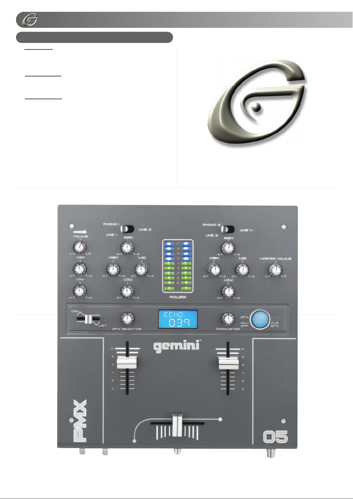
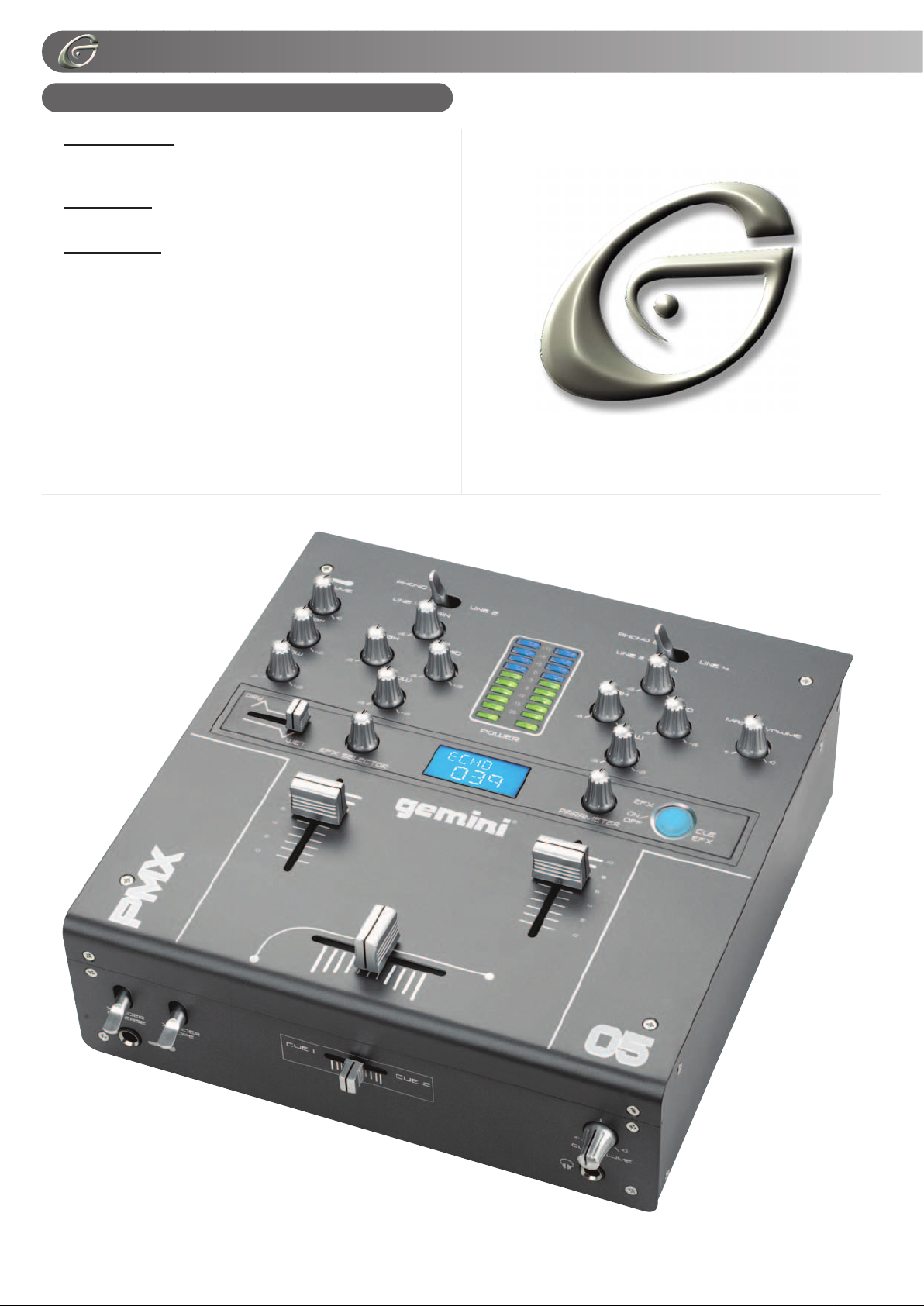
Congratulations on your purchase of a GEMINI PMX-05 10" 2
Channel Stereo Mixer. This state-of-the-art mixer features the
latest technological advances and is backed by a 3 year warranty, excluding the crossfader. The crossfader is backed by a separate 90 day warranty. Prior to use we suggest that you carefully read all the instructions.
FEATURES:
- 10" 2 stereo channel EFX mixer
- 4 line, 2 convertible phono/line, RCA inputs
- Dual ground screws for easy connectivity
- Master and record RCA outputs
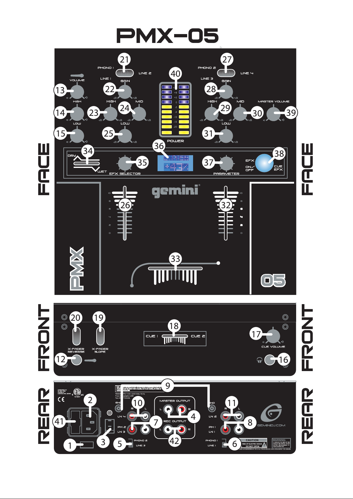
FACE:
- 3 band rotary EQ control with cut feature
- Bright blue LCD display
- DSP module with 26 effects & a wide range of parameters
- Dry/Wet fader control
- Rotary control EFX selector
- Rotary parameter control
- Large backlit soft touch on/off button
- Removable face plate for user replaceable Rail Glide cross fader
- Ergonomically designed to be flush with turntable
- Smooth curved face plate
- Rotary gain channel control
- Dual VU display with bright LED
- 2 band rotary Mic EQ & volume controls
FRONT:
- Hamster/reverse & cross fader curve control switches
- Rotary cue volume control & cue section fader allowing cue mix
- 1/4" Mic input & headphone output
PRECAUTIONS:
1. All instructions should be read before using this equipment.
2. To reduce the risk of electrical shock, do not open the unit.
Please refer all servicing needs to a GEMINI-qualified service
technician.
IN THE USA ~ IF YOU EXPERIENCE PROBLEMS WITH THIS UNIT
CALL GEMINI CUSTOMER SERVICE AT: 1 (732) 738-9003. DO NOT
ATTEMPT TO RETURN THIS EQUIPMENT TO YOUR DEALER.
3. Do not expose this unit to direct sunlight or a heat source such
as a radiator or stove.
4. This unit should be cleaned only with a damp cloth. Avoid solvents or other cleaning detergents.
5. When moving this equipment it should be placed in its original carton and packaging. This will reduce the risk of damage
during transit.
6. DO NOT EXPOSE THIS UNIT TO RAIN OR MOISTURE.
7. DO NOT USE SPRAY CLEANERS OR LUBRICANTS ON
CONTROLS, SURFACES OR SWITCHES.
CONNECTIONS:
1. Before plugging this unit into any outlet, make sure that the
VOLTAGE SELECTION SWITCH (1) is set to the proper voltage. To change the selection, unscrew the hard plastic protective top with a Phillips head screw driver. Then use a flat head
screw driver to move the switch to the proper selection
(115V/230V). Replace the hard plastic protective top, and screw
into the unit.
2. Ensure that the POWER SWITCH (3) is in the OFF position
prior to making any connections. Plug into the rear panel
POWER JACK (2) before plugging it into a proper power
source.
NOTE: LOCATED BY THE POWER CORD JACK (2) IS A 250V FUSE (41) TO
PROTECT AGAINST ELECTRICAL SURGES. TO REPLACE THE FUSE,
PLACE AFLAT HEAD SCREWDRIVER INTO THE GROOVE LOCATED INSIDE
THE POWER CORD JACK (2) AND POPTHE FUSE OUT. REPLACE THE FUSE
WITH ONLYA250V FUSE.
3. The PMX-05 has 2 sets of outputs:
- The MASTER OUTPUT (4) jacks also connect to the main
amplifier with RCA cables.
- The REC OUTPUT (42) jacks can be used to connect the
mixer to the record input of your recording unit, thus enabling
you to record your mix by connecting these units with RCA
cables.
4. Headphones may be plugged into the front panel-mounted
HEADPHONES (16) ¼" jack.
5. Microphones may be plugged into the front panel-mounted
MICROPHONE (12) ¼" jack.
6. The PMX-05 has 2 CONVERTIBLE PHONO/LINE (7, 8) RCA
inputs located on the rear panel on either side of the MASTER
RCA (4) input. Facing the rear panel, the convertible RCA Input
on your right is for PHONO 1/ LINE 1 (8). The convertible RCA
input on your left is for PHONO 2/ LINE 3 (7). Using the
PHONO/ LINE CONVERTER (5, 6) SWITCHES, located just
below each input, you may convert the PHONO (PH) to LINE
(LN) and vice versa. Plug the RCA's from your playable medium
into each input to be connected to their respective channels
(CH). The PH INPUTS only accept turntables with a magnetic
cartridge. The STEREO LINE INPUTS only accept line level
inputs such as a CD, DAT, MiniDisc, etc and require the LINE
setting using the PH/LN CONVERTER (5, 6) switches.
7. When using (a) turntable(s), you will need to ground the RCA
cable(s) by screwing in the grounding fork(s) to the GROUND-
ING SCREWS (9) located in the rear panel of the PMX-05 mixer.
Attach each PH ground line to one of the DUAL GROUND
THUMB SCREWS (9). These are adjacent to each RCA PH
input.
NOTE: WHEN USING TURNTABLES, NOT ATTACHING A GROUND MAY
CAUSE A SYSTEM "HUM."
OPERATING INSTRUCTIONS:
1. POWER ON: Once all equipment connections have been
made, press POWER SWITCH (3). Power is ON when the VU
METER LED (40) is illuminated.
2. CH 1: The GAIN (22), HIGH (23), MID (24), and LOW (25)
controls allow you to fully adjust the selected source. The PH-
1/LN-1 CONVERTER (6) switch located on the rear panel
allows you to select PH 1 or LN 1. The LN SWITCH (21) located on the front allows you to switch from PH 1 to LN 2 or LN 1
to LN 2. CH 1 FADER (26) controls the input level of this chan-
nel.
3. CH 2: The GAIN (28), HIGH (29), MID (30), and LOW (31)
controls allow you to fully adjust the selected source. The PH-
2/LN-3 CONVERTER (5) located on the rear panel allows you to
select PH 2 or LN 3. The LN SWITCH (27) located on the front
allows you to switch from PH 2 to LN 4 or LN 3 to LN 4. CH 2
FADER (32) controls the input level of this channel.
NOTE: FOR OPTIMAL PERFORMANCE, BEGIN PROGRAM MIX WITH
ROTARY GAIN (22, 28) CONTROLS SET TO ZERO (ROTATE IT COUNTERCLOCKWISE TO THE LEFT POSITION). MAKE ALL ADJUSTMENTS IN
SOUND OUTPUT WITH THE USE OF YOUR CH FADER CONTROLS (26, 32)
AND MASTER (39) VOLUME ROTARY CONTROLS. THIS WILL PREVENT SIGNAL OVERLOAD AND DECREASE DISTORTION. ONCE YOU HAVE MODIFIED YOUR SOUND AND WOULD LIKE TO INCREASE THE OUTPUT OF
YOUR SOUND, THEN YOU MAY ADJUST THE ROTARY GAIN CONTROL IF
NEEDED.
4. CROSSFADER SECTION: The CROSSFADER (33) allows
the mixing of one source into another. The left side of the
CROSSFADER (33) is CH 1 (26) while the right belongs to CH
2 (32). You may also reverse this default by flipping the
REVERSE (20) switch. See the CROSSFADER REVERSE sec-
tion for more info. The CROSSFADER(33) in your unit is removable and if the need arises can be easily replaced. Your GEMINI
mixer comes with an RG-45 (RAILGLIDE™) DUAL-RAIL
CROSSFADER. RAIL GLIDE™ CROSSFADERS have internal
dual stainless steel rails that allow the slider to ride smoothly and
accurately from end to end. Also available is our is the RG-45
PRO (RAIL GLIDE™) CROSSFADER with a special curve
(44)
Page 5
PPMMXX-0055
PPMMXX-0055
designed for scratch mixing. Just purchase one from your
GEMINI dealer and follow the instructions:
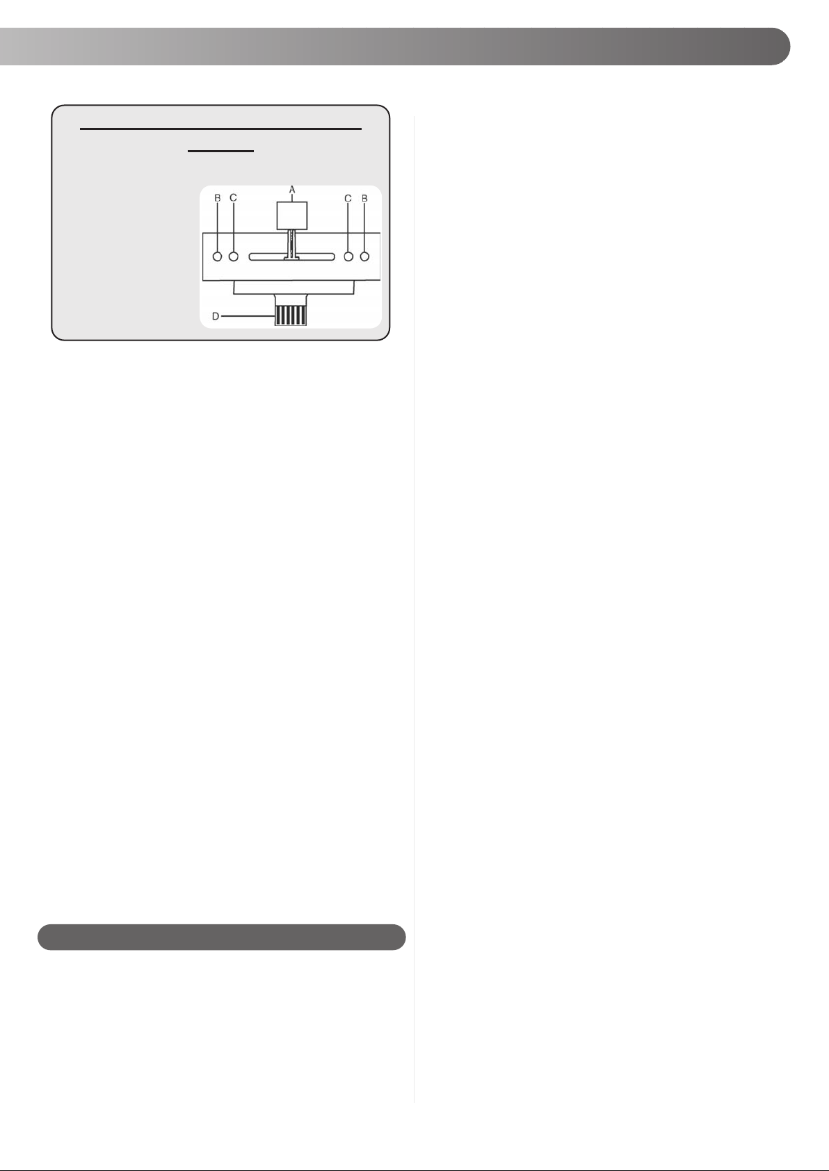
USER REPLACEABLE CROSS
FADER
1. UNSCREW THE OUTSIDE MIXER FACE PLATE SCREWS AND
REMOVE THE FACE PLATE. THEN REMOVE FADER PLATE SCREWS
(B & C).
2. CAREFULLY LIFT THE
FADER AND UNPLUG THE
CABLE (D).
3. PLUG THE NEW FADER
INTO THE CABLE AND
PLACE IT BACK IN THE
MIXER.
4. SCREW FADER PLATE
TO THE MIXER AND
REPLACE THE MIXER FACE
PLATE.
NOTE: DO NOT APPLY PRESSURE WHILE USING THE CROSSFADER.
LIGHTLY GLIDE THE CROSSFADER BACK AND FORTH. PRESSING DOWN
ON THE CONTROLS CAN BEND CONTACTS AND CAUSE A LOSS OF
SOUND.
5. CROSSFADER SLOPE: The CROSSFADER SLOPE
SWITCH (19) allows you to adjust the kind of slope the CROSSFADER (33) has. Flip the CROSSFADER SLOPE SWITCH (19)
up to make the slope steep and cutting (perfect for scratching).
Flip the CROSSFADER SLOPE SWITCH (19) down to make
the slope gradual and gentle.
6. CROSSFADER REVERSE: The CROSSFADER REVERSE
SWITCH (20) allows you to reverse the CROSSFADER (33) so
that CH 2 (32) is controlled by the left side of the CROSSFAD-
ER (33) and CH 1 (26) is controlled by the right side of the
CROSSFADER (33).
7. CUE: The CUE FADER (18) facilitates the seamless blending
of one recorded track into another. Connecting a set of headphones to the HEADPHONES (16) jack allows you to monitor
either CH 1 (26) or CH 2 (32). Select CH 1 (26) by moving CUE
FADER (18), located on the front panel, to CUE 1 on the left.
Listen to CH 2 (32) by moving CUE FADER (18) to CUE 2 on
the right. To mix both Channels bring CUE FADER (18) to the
middle so that both tracks may be heard. Use CUE VOLUME
(17) to adjust the headphone volume without affecting the
speaker-driven mix.
8. MIC SECTION: Connecting a microphone to the 1/4" MIC
JACK (12) allows voice amplification through the mixer to the
stereo through the MASTER RCA OUTPUTS (4). This is controlled by the MIC VOLUME (13), HIGH (14), LOW (15) rotary
controls.
9. OUTPUT CONTROL SECTION: The level of the MASTER
RCA (4) output is controlled by the MASTER VOLUME (39)
rotary control.
10. DISPLAYS: The DUAL VU METER (40) indicates the level
of the MASTER RCA (4) output left and right channel levels
respectively.
DUAL VU METER (40) reflects the MASTER VOLUME (39), GAIN (22, 28), HIGH (23, 29), MID (24, 30) and LOW
(25, 31) rotary control adjustments for each channel. The CH
FADER (26, 32) also affect each of the DUAL VU METER (40).
EFX SECTION:
NOTE: WHEN USING THE EFX SECTION, YOU MAY EXPERIENCE A TONAL
BOOST THAT WILLSEND YOUR MASTER OUTPUT LEVELS INTO THE BLUE
(0 THROUGH +11), AS INDICATED IN YOUR VU METER (40). ADJUST THE
CHANNEL FADERS (26, 32), IN ORDER TO PROTECT YOUR EQUIPMENT
FROM A SYSTEM OVERLOAD. TO BEGIN EFX EXPERIMENTATION, START
WITH ALOW PARAMETER SETTING WITH YOUR CHANNEL FADERS (26, 32)
AT MID LEVEL. THEN MOVE SLOWLY THROUGH THE EFX PARAMETERS TO
EXAMINE THE TONAL BOOST, SAFELY.
The PMX-05 is equipped with DIGITALSIGNAL PROCESSOR
(DSP) effects. This means you may augment the audio output of
your program mix by processing tones through the 26 different
effects. When an audio signal is processed through the DSP, a
wide range of effects can be achieved with the PMX-05 EFX
section. Please follow these instructions to operate the EFX sec-
tion of your mixer:
1. DRY/WET FADER:To control this section you must adjust the
DRY/WET FADER (34) in order to increase the level of the
effect. Glide the DRY/WET FADER (34) to the RIGHT to
increase the effect, saturating the PGM with WET effects. Glide
the DRY/WET FADER (34) to the LEFT or DRY area to
decrease the effect, thus disabling all effects.
2. EFX ON/OFF: The EFX ON/OFF (38) button has multiple
functions:
- PGM MODE: Tap the EFXON/OFF (38) button. The blue LED
will turn on to indicate that the DSP effects feature has been
engaged in PGM mode. Tap the EFX ON/OFF (38) button again
and the DSP effects will be disengaged as the LED turns off.
When using the EFX ON/OFF (38) button, you will notice that
once an effect has been engaged, the effect will not change
when scrolling through the EFX selections, using the EFX
SELECTOR (35) as instructed below to find a new effect.
Adjusting the PARAMETER (37) rotary control setting will only
change the engaged effect. In order to change the effect you
must press the EFX ON/OFF (38) button to engage the next
effect and adjust PARAMETER settings.
- CUE MODE: For monitoring in your headphones without
changing the PGM, press and hold the EFX ON/OFF (38) button
until the button starts to blink slowly to indicate that the DSP
effects are engaged in CUE mode. To disengage the CUE
mode, press and hold the EFX ON/OFF
(38) button until the
EFX ON/OFF (38) stops blinking.
To disengage the EFX in CUE mode, tap the EFX ON/OFF (38)
button, and you will monitor the CUE without effects. The EFX
ON/OFF (38) button begins blinking shortly indicating that the
DSP effects are not engaged in CUE MODE. To engage the
DSP, tap the EFX ON/OFF (38) button to engage the DSP EFX.
3. PARAMETER: To adjust the PARAMETER, or dynamics of
the effect signal, use the PARAMETER (37) rotary knob to
expand or minimize the effect level of the DSP effects. Rotate
this knob clockwise to expand the effect. Rotate this knob counter clockwise to minimize the effect.
When an effect has been engaged, you will notice that scanning through the effects selection will not change the effect.
Adjusting the parameter setting will only change the engaged
effect. Follow the EFX instructions to change the effect and then
you may use the parameter control to adjust the parameter setting of the engaged effect.
4. LCD: The blue LCD (36) shows the EFX selection abbreviated name, to indicate which effect is activated or which effect
may be activated at the top part of the screen. While the bottom
part of the screen displays the PARAMETER level as controlled by
the PARAMETER (37) rotary knob.
5. EFX SELECTOR: Use the EFX (35) rotary knob to scan
through the 26 DSP effects as indicated in the blue LCD (36)
display. Once you have found an effect you would like to
engage, press the EFX ON/OFF (38) button to preview the DSP
effect. The EFX (35) rotary control can rotate 360owhile scanning through the effects. Rotate the EFX (35) knob clockwise to
scan forward through the EFX list. Rotate the
EFX (35) rotary
control counterclockwise to scan backwards through the EFX
list. The effects are listed on page 15.
NOTE: WHEN SCROLLING THROUGH THE EFFECTS YOU WIL FIRST SEE
THE NUMBER OF THE EFFECT, THEN THE LCD (36) WILL AUTOMATICALLY
SWITCH THE VIEW TO THE PARAMETER SETTING. THIS WILL AID IN
SCROLLING TO AN EFFECT QUICKLY BY FINDING THE NUMBER OF THE
EFFECT.
(5)
Page 6
SPECIFICATIONS:
INPUTS:
DJ Mic................................................1.5 mV 1 kOhm Balanced
Phono.................................................................3 mV 47 kOhm
Line................................................................150 mV 10 kOhm
OUTPUTS:
Amp................................................................0 dB 1V 400 Ohm
Max................................................................20V Peak to Peak
GENERAL:
Bass (Channels 1-2)............................................+12 dB -32 dB
Mid (Channels 1-2)..............................................+12 dB -32 dB
High (Channels 1-2)............................................+12 dB -32 dB
Gain (Channels 1-2)................................................. 0 to -20 dB
Frequency Response...............................20 Hz-20 kHz +/- 2 dB
Distortion........................................................Less Than 0.02%
S/N Ratio.......................................................Better Than 80 dB
Headphone Impedance.................................................16 Ohm
Power Source......................................................1 15V/60Hz AC
........................................................................or 230V/50Hz AC
Unit Dimensions...W 10" x H 3.3" x D 10.25" (254 x 84 x 260 mm)
Weight...............................................................7.48 lbs (3.4 kg)
SPECIFICATIONS AND DESIGN ARE SUBJECT TO CHANGE WITHOUT NOTICE FOR PURPOSE OF IMPROVEMENT.
(6)
Page 7

EINLEITUNG:
Wir gratulieren Ihnen zum Kauf eines GEMINI PMX-05
Mischpults. Dieses moderne Mischpult ist nach dem neuesten
Stand der Technik hergestellt und mit dreijähriger Garantie,
ausschließlich Crossfader und Kanalfader, ausgestattet. Vor
Anwendung dieses Mischpults bitte alle Anweisungen sorgfältig
durchlesen.
FUNKTIONEN:
- 10" 2-Kanal-Stereo-Effekt-Mixer
- 4 Line, 2 umschaltbare Phono/Line, Cincheingänge
- 2 Erdunsschrauben für Maseanschluß
- Master und record cinchausgänge
FRONTPLATTE:
- 3 Band-EQ mit Cutfunktion und Drehreglern
- Blaues-LCD-Display
- 26 DSP-Effektsektion mit Parametern funktion
- Dry/Wet- Regelung per Fader
- Drehschalter für Effektwahl
- Drehschalter zur Parametereinstellung
- Großer, beleuchteter On/Off-Knopf
- Einfach auszutauschender Rail-Glide-Crossfader
- Ergonomisches Design
- Abgerundete Fronplatte
- Gaindrehregler pro Kanal
- Zweifach-Mode-Anzeige mit LED
- 2-Band-Eq und Volumedrehregler für Mikrofon auf der
Frontplatte
FRONTSEITE:
- Schalter für X-Fader-Reverse und Kurveneinstellung auf der
Vorderseite
- Cuesektion mit Volumedrehregler und Cue-Mix-Fader auf der
Frontseite
- 6.3 mm Klinkenbuchsen für Kopfhörer und Mikrofon auf der
Vorderseite
VORSICHTSMAßNAHMEN:
1. Vor Anwendung dieses Geräts bitte alle Anweisungen
sorgfältig durchlesen.
2. Das Gerät nicht öffnen, um das Risiko elektrischen Schocks
zu vermeiden. Es enthält KEINE VOM ANWENDER ERSET-
ZBAREN TEILE. Die Wartung darf nur von befähigten
Wartungstechnikern durchgeführt werden.
3. Das Gerät nicht direktem Sonnenlicht oder einer
Wärmequelle wie Heizkörper oder Ofen aussetzen.
4. Dieses Gerät darf nur mit einem feuchten Tuch gesäubert
werden. Keine Lösungs- oder Reinigungsmittel benutzen.
5. Bei Umzügen sollte das Gerät in seinem ursprünglichen
Versandkarton und Verpackungsmaterial verpackt werden.
Dadurch verhindert man, daß das Gerät während des
Transportes beschädigt wird.
6. DIESES GERÄT NICHT REGEN ODER FEUCHTIGKEIT
AUSSETZEN.
7. AN DEN REGLERN ODER SCHALTERN KEIN SPRAYREINIGUNGSMITTEL ODER SCHMIERMITTEL BENUTZEN.
SONST ERLISCHT DER GARANTIEANSPRUCH.
ANSCHLÜSSE:
1. Bevor Sie den Mixer an eine Steckdose anschließen, stellen
Sie sicher, daß der VOLTAGE SELECTION SWITCH (1)
(SPANNUNGSWAHLSCHALTER) auf die vorhandene
Netzspannung eingestellt ist. Um die Einstellung zu ändern,
lösen Sie die Schraube der Plastiksicherung mit einem
Kreuzschlitzschraubendreher und drehen sie die
Plastiksicherung zur Seite. Schieben Sie nun mit einem
schmalen Schlitzschraubendreher den Spannungswahlschalter
in die richtige Position (115 V/230 V).
PPMMXX-0055
PPMMXX-0055
Vergewissern Sie sich das der NETZSCHALTER POWER
SWITCH (3) ausgeschaltet ist bevor Sie den Mixer
anschliessen. Stecken Sie das mitgelieferte Netzkabel in die
Netzbuchse POWER CORD (2) jack bevor Sie es in die
Steckdose stecken.
ANMERKUNG: IN DIE NETZBUCHSE (2) INTEGRIERT IST EIN
SICHERUNGSHALTER MIT EINER NETZSICHERUNG. ZUM AUSTAUSCHEN
DER SICHERUNG STECKEN SIE EINEN SCHLITZSCHRAUBENDREHER IN
DIE INNERE AUSBUCHTUNG DER NETZBUCHSE UND DRÜCKEN SIE DEN
SICHERUNGSHALTER HERAUS. ERSETZEN SIE DIE SICHERUNG DURCH
EINE NEUE GLEICHEN TYPS.
3. Der PMX-05 verfügt über 2 Ausgangsbuchsenpaare:
- Die Buchsen MASTER OUTPUT (4) sind unsymmetrisch und
dienen zum Anschluß an den Hauptverstärker (kurze Kabel).
- Die Buchsen REC OUTPUT (42) können dazu dienen, das
Mischpult an den Aufnahmeeingang des Aufnahmegerätes
anzuschließen um die Tonmischung aufnehmen zu können.
4. Kopfhörer können an die 6.3 mm Klinkenbuchse HEAD-
PHONE (16) an der Frontseite angeschlossen werden.
5. Ein Mikrofon ist an die 6.3 mm Klinkenbuchse MICRO-
PHONE (12) anschliessbar.
6. Der PMX-05 hat 2 umschaltbare PHONO/LINE (PH/LN)
Cincheingänge (7, 8). Diese befinden sich auf der Rückseite.
Auf die Rückseite gesehen sind die rechten Cinchbuchsen für
PH 1/LN 1 (8), die mittleren für PH 2/LN 3 (7). Die Umschaltung
erfolgt mit den, unter den Cinchbuchsen befindlichen Schaltern
PH/LN (5, 6). Verbinden Sie Ihr Abspielgerät mit einem
Cinchkabel mit dem Eingang des gewünschten KANALS (CH).
An die Phonoeingänge PH INPUTS (7, 8) können nur
Plattenspieler mit Magnetsystem angeschlossen werden. Die
Lineeingänge STEREO LN INPUTS (7, 8, 10, 11) dienen zum
Anschluß von CD, DAT, Mini Disc- Playern usw.
7. Wenn Sie Plattenspieler an den Mixer anschliessen, achten
Sie darauf, daß das Massekabel der Cinchleitung an die
Erdungsschrauben GROUNDING SCREWS (9) an der
Rückseite des PMX-05 angeschlossen wird.
ANMERKUNG: WIRD EIN PLATTENSPIELER OHNE MASSEVERBINDUNG
2.
BEDIENUNG:
(ERDUNG) BETRIEBEN, KÖNNEN BRUMMGERÄUSCHE AUFTRETEN.
1. STROM EIN: Nachdem Sie alle Geräte am Mischpult
angeschlossen haben, stecken Sie das Steckernetzteil in eine
Schukosteckdose (230V)und drücken Sie auf die Taste POWER
(3). Die Aussteuerungsanzeige VU-METER (40)leuchtet auf.
2. KANAL 1: Die EQ-Regler GAIN (22), HIGH (23), MID (24),
LOW (25) dienen zur Anhebung /Absenkung der Höhen, Mitten
und Tiefen.Der GAIN (22)-Regler erlaubt Ihnen, die Signalstärke
des Kanals individuell zu regulieren. SCHALTER (21)
ermöglicht, den Eingang von PHONO 1/LINE 1 (8) oder LINE 2
(1 1) auszuwählen. CHANNEL1 FADER(26) (Kanalfader) regelt
den Ausgangspegel dieses Kanals.
3. KANAL 2: Die EQ-Regler GAIN (28), HIGH (29), MID (30),
LOW (31) dienen zur Anhebung /Absenkung der Höhen, Mitten
und Tiefen.Der GAIN (28)-Regler erlaubt Ihnen, die Signalstärke
des Kanals individuell zu regulieren. SCHALTER (27)
ermöglicht, den Eingang von PHONO 2/LINE 3 (7) oder LINE 4
(10) auszuwählen. CHANNEL 2 FADER (32) (Kanalfader) regelt
den Ausgangspegel dieses Kanals.
HINWEIS: ZUR INDIVIDUELLEN KLANGREGELUNG, IST JEDER KANAL MIT
EINEM 3-BAND EQ AUSGESTATTET. DADURCH IST EINE
KLANGVERÄNDERUNG IN WEITEN BEREICHEN MÖGLICH.
4. CROSSFADER SEKTION (ÜBERBLENDER): Der
CROSSFADER (33) ermöglicht das Mixen von einem Kanal
zum Anderen. Der PMX-05 ist mit einem RG-45 (RAILGLIDE™)
DUAL-RAIL CROSSFADER ausgestattet, welcher im
Servicefall leicht austauschbar ist. RAIL GLIDE™
CROSSFADER sind mit Doppel-Edelstahlschienen ausgestat-
tet, die ein sanftes Gleiten zwischen beiden Endpunkten
(77)
Page 8

ermöglichen. Lieferbar ist ausserdem der RG-45 PRO
(PROGLIDE™), der speziell für das Scratchen designed wurde:
EINFACH AUSZUTAUSCHENDER
RAIL-GLIDE-CROSSFADER
1. DIE ÄUßEREN SCHRAUBEN DER CROSSFADERPLATTE (B) LOSSCHRAUBEN. NICHT DIE INNENSCHRAUBEN (C) LOSSCHRAUBEN.
2. DEN ÜBERBLENDER VORSICHTIG ANHEBEN UND DAS
KABEL (D) ABZIEHEN.
3. DAS KABEL AUF DEN
NEUEN FADER STECKEN
UND WIEDER IN DAS
MISCHPULT SETZEN.
4. DEN NEUEN
CROSSFADER MIT DEN
SCHRAUBEN AM
MISCHPULT BEFESTIGEN.
ANMERKUNG: ÜBEN SIE KEINEN STARKEN DRUCK VON OBEN AUF DEN
CROSSFADER (33) AUS. ES KANN SONST ZU AUSSETZERN UND
KONTAKTPROBLEMEN KOMMEN.
5. Die CROSSFADER CURVE-TASTE (19) ermöglicht die jew-
eilige Art der Kurve des CROSSFADERS einzustellen. Drücken
Sie auf die CROSSFADER CURVE-TASTE um die Kurve steil
und scharf zu machen (ideal für Scratchen). Lösen Sie die
CROSSFADER CURVE-TASTE aus um die Kurve sanft und
weich zu machen.
6. Der CROSSFADER REVERSE SWITCH (20) ermöglicht die
Umkehrfunktion des CROSSFADERS KANAL 2 (32) wird nun
kontrolliert durch die linke Seite des Crossfader und KANAL 1
(26) durch die rechte Seite.
HINWEIS: IST DER CROSSFADER REVERSE-SCHALTER (20) AKTIVIERT
(NACH RECHTS GESCHOBEN), LÄUFT NUR DER CROSSFADER GEGENLÄUFIG. DIE KANALFADER UND ALLE ANDEREN DREHREGLER UND
SCHALTERN NICHT!
7. AUSGANGSREGELUNG: Der Pegel des MASTER OUTPUT
(4) (Verstärkerausgang) wird mittels des Drehreglers MASTER
(39) gesteuert.
8. MIC SECTION: Ein Mikrophon bis das erlaubt 1/4" MIC
JACK (12) anschließend,Sprachverstärkung durch den Mischer
zum Stereo durch dieVorlagenausgänge. Dieses wird durch die
Drehsteuerungs des HIGH (14), LOW (15) VOLUMENS MIC
(13) gesteuert.
9. CUE: Indem Sie die Kopfhörer an der KOPFHÖRER-
BUCHSE (16) anschließen, können Sie einen oder beide
Kanäle zusammen überwachen. Den CUE-SCHALTER (18)
nach links schieben, um KANAL 1 (26) zu überwachen. Den
CUE-SCHALTER (18) nach rechts schieben, um KANAL 2 (32)
zu überwachen. Mit Hilfe des CUE-PEGEL-REGLERS (17)
kann die Kopfhörerlautstärke eingestellt werden, ohne dabei die
allgemeine Tonmischung zu beeinträchtigen.
10. DISPLAY: Die Doppelfunktionsanzeige DISPLAY (40) gibt
eine Darstellung entweder der Pegel des MASTER-(4)
Ausgangs links und rechts oder der Pegel der Kanäle 1 und 2.
Die gewünschte Option kann durch Druck auf die Taste DIS-
PLAY (40) gewählt werden.
ZU BEACHTEN: WENN DAS DISPLAY(40) SICH IM ANZEIGEMODUS KANAL
1/KANAL 2 BEFINDET, KANN DAS SIGNAL MITTELS DER JEWEILIGEN
GAINREGLER VERSTÄRKT ODER VERRINGERT WERDEN, UM ES DEM
SIGNAL DES ANDEREN KANALS ANZUPASSEN. DIE KANALFADER UND
DER CROSSFADER HABEN KEINEN EINFLUß AUF DIE ANZEIGEWERTE.
EFFEKT-SEKTION:
ACHTUNG: WENN SIE DIE EFFEKT-SEKTION BENUTZEN, KANN ES SEIN,
DASS DURCH DIE EFFEKTE EINE ZUSÄTZLICHE ERHÖHUNG DES PEGELS
AUFTRITT UND DER AUSGANGSPEGEL DEUTLICH ANSTEIGT, WAS SIE
AUCH AN DEN VU-METERN (40) ABLESEN KÖNNEN. STELLEN SIE DIE
KANAL-FADER (26, 32) SO EIN, DASS DER PEGEL NACHFOLGENDES
EQUIPMENT NICHT SCHÄDIGEN ODER ÜBERSTEUERUNGEN ERZEUGEN
KANN. WENN SIE DIE EFFEKTE AUSPROBIEREN, REGELN SIE DIE
PARAMETER AUF EIN NIEDRIGES NIVEAU UND STELLEN SIE DIE KANALFADER (26, 32) AUF EINEN MITTLEREN WERT. JETZT KÖNNEN SIE
LANGSAM DIE EFX PARAMETERS ERHÖHEN, UM HERAUSZUFINDEN, WIE
STARK DER PEGELANSTIEG IST.
Der PMX-05 ist mit DSP- (Digitaler Signalprozessor) Effekten
ausgestattet. Der Einsatz der 26 unterschiedlichen Effekte kann
dazu führen, dass der Ausgangspegel Ihres Mischers sich
erhöht. Wenn Sie ein Audiosignal mit den DSP-Effekten bearbeiten, können Sie mit der Effektsektion des PMX-05 eine
Vielzahl unterschiedlicher Ergebnisse erzielen.
1. DRY/WET FADER: Um die Effekt-Sektion einzustellen,
müssen Sie durch Regeln des DRY/WET FADER (34) den
Effektanteil erhöhen. Schieben Sie den DRY/WET FADER (34)
nach rechts, um den Effektanteil zu erhöhen und den
Programmmix mit Effektklang anzureichern. Schieben Sie den
DRY/WET FADER (34) nach links, um den Effektanteil zu verringern oder die Effekte komplett zu deaktivieren.
2. EFX ON/OFF: Der EFX ON/OFF-KNOPF (38) hat ver-
schiedene Funktionen:
- PGM MODUS: Betätigen Sie den EFX ON/OFF-KNOPF (38)
an. Die blaue LED geht an und zeigt, dass die Effektsektion jetzt
im PGM-MODUS arbeitet. Erneutes Betätigen des Knopfs
schaltet die Effektsektion aus und die LED erlischt.
Wenn Sie den EFX ON/OFF-KNOPF (38) benutzen, werden
Sie feststellen, dass der gewählte Effekt sich auch dann nicht
verändert, wenn Sie die Effektsektion mit dem EFX SELECTOR
(35) wie unten beschrieben durchsuchen, um einen neuen
Effekt zu finden. Änderungen am PARAMTER-DREHREGLER
(37) betreffen nur den gerade aktiven Effekt.
Um den neuen Effekt zu aktivieren, müssen Sie den EFX
ON/OFF-KNOPF (38) drücken und können dann dessen
Parameter einstellen.
- CUE MODE: Zum Abhören im Kopfhörer mit Effekt, ohne
dabei das Programmsignal verändern zu müssen, drücken Sie
den EFX ON/OFF-KNOPF (38) so lange, bis der EFX ON/OFF-
KNOPF (38)anfängt, langsam zu blinken und damit anzeigt,
dass die DSP-Effekte im CUE-MODUS eingeschaltet sind. Um
sie wieder auszuschalten, halten Sie den EFX ON/OFF-KNOPF
(38) erneut gedrückt, bis der EFX ON/OFF-KNOPF (38)aufhört,
zu blinken.
Um die Effekte im CUE-MODUS zu deaktivieren, drücken Sie
den EFX ON/OFF-KNOPF (38) und Sie werden den CUE ohne
Effekte hören. Der EFX ON/OFF-KNOPF (38) beginnt kurz zu
blinken und zeigt damit an, dass keine DSP-Effekte mehr aktiv
sind. Um die DSP-Effekte wieder einzuschalten, drücken Sie
den EFX ON/OFF-KNOPF (38).
3.
PARAMETER: Wenn Sie Parameter oder die Dynamik des
Effektsignals einstellen möchten, benutzen Sie den PARAME-
TER-Drehregler (37), um den Effektanteil zu erhöhen oder zu
verringern. Drehen Sie den PARAMETER-Drehregler (37) im
Uhrzeigersinn, um den Effektanteil zu erhöhen. Drehen Sie den
PARAMETER-Drehregler (37) gegen den Uhrzeigersinn, um
den Effektanteil zu verringern.
4. LCD: Das blaue LCD-Display (36) zeigt die Namenskürzel
der Effektsektion im oberen Bereich, damit Sie wissen, welcher
Effekt aktiviert ist oder welcher Effekt als nächster aktiviert werden kann. Im unteren Bereich wird der jeweilige Parameter
angezeigt, der vom PARAMETER-Drehregler (37) verändert
werden kann.
5. EFX SELECTOR: Benutzen Sie den EFX SELECTORDrehregler (35), um durch die 26 DSP-Effekte zu scrollen, die im
blauen LCD-Display angezeigt werden (36). Haben Sie einen
Effekt gefunden, den Sie gerne benutzen würden, halten Sie
den EFX ON/OFF-Knopf (38) gedrückt, um eine Vorschau des
DSP-Effekts zu erhalten. Der EFX SELECTOR-Drehregler (35)
ist ein Endlosdrehregler. Drehen Sie den EFX SELECTORDrehregler (35) im Uhrzeigersinn, um vorwärts durch die
Effektliste zu scrollen. Drehen Sie den EFX SELECTORDrehregler (35) entgegen dem Uhrzeigersinn, um rückwärts
durch die Effektliste zu scrollen. Eine Übersicht der Effekte finden Sie auf Seite 15.
ACHTUNG: WENN SIE DURCH DIE EFFEKTLISTE SCROLLEN, SEHEN SIE
ZUERST DIE NUMMER DES EFFEKTS. DAS LCD-DISPLAY (36) SCHALTET
AUTOMATISCH AUF DIE PARAMETER UM. DADURCH KÖNNEN SIE
EFFEKTE SCHNELLER NUR ANHAND DER NUMMERN FINDEN.
(8)
Page 9

SPEZIFIKATIONEN:
EINGÄNGE:
DJ-Mikrophon......................................1.5 mV 1 kOhm Balanced
Phono..................................................................3 mV, 47 kOhm
Line..................................................................150 mV, 10 kOhm
AUSGÄNGE:
Verstärker........................................................0 dB 1 V 400 Ohm
Max.................................................................20 V Spitze-Spitze
ALLGEMEINES:
Tiefenregler (Kanäle 1 - 2)....................................+ 12 dB/-32 dB
Mittenregler (Kanäle 1 - 2)....................................+ 12 dB/-32 dB
Höhenregler (Kanäle 1 - 2)...................................+ 12 dB/-32 dB
Gainregler (Kanäle 1 - 2)...........................................0 bis -20 dB
Frequenzgang.......................................20 Hz - 20 kHz +/- 2 dB
Klirrfaktor.........................................................................< 0.02%
Störabstand.......................................................besser als 80 dB
Kopfhörerimpedanz.........................................................16 Ohm
Stromversorgung.....................................115V/230V 60Hz/50Hz
Abmessungen................................................254 x 84 x 260 mm
Gewicht..............................................................................3.4 kg
TECHNISCHE ÄNDERUNGEN VORBEHALTEN.
PPMMXX-0055
PPMMXX-0055
(9)
Page 10

INTRODUCCIÓN:
Felicitaciones por su compra del mezclador PMX-05 de
Gemini. Este mezclador de la más avanzada tecnología está
dotado de características ultramodernas y está respaldado por
una garantía de tres años, salvo el crossfader y los faders de
canal. Antes de usarlo, le recomendamos leer cuidadosamente
todas las instrucciones.
CARACTERÍSTICAS:
- Mezclador Estéreo 10" de 2 canales
- Entradas RCA 4 Línea, 2 convertibles Phono/Línea
- Doble toma de tierra para fácil conexión
- Salida RCA para master y grabación
CARATULA:
- EQ rotativo de 3 Bandas con sistema Cut
- Display brillante azul LCD
- Modulo de 26 efectos DSP
- Nivel de efectos
- Control rotativo de selección EFX
- Control rotativo de parámetros
- Control On/Off de efectos con luz trasera
- Carátula fácilmente removible para cambiar el Crossfader por
parte del usuario
- Diseño ergonómico para encajar con los giradiscos
- Carátula curvada suavemente
- Control de Ganancia rotativo
- Doble Display de Modo con LED
- EQ rotativo de 2 bandas para micrófono en panel principal
FRONTAL:
- Reverse & Control de curva del Cross Fader en frontal
- Volumen Cue rotativo y Fader de Cue en p anel frontal con Cue Mix
- Salida auriculares y entrada micrófono jack ¼" en panel frontal
PRECAUCIONES:
1. Deberán leerse todas las instrucciones de operación antes
de usar el equipo.
2. Para reducir el riesgo de shock eléctrico, no abra esta
unidad. NO CONTIENE PIEZAS REEMPLAZABLES POR EL
USUARIO. Por favor, refiera el servicio a un técnico de servicio calificado.
3. No exponga la unidad a la luz solar directa ni a una fuente
de calor, por ejemplo, un radiador o estufa.
4. Esta unidad sólo deberá limpiarse con un paño húmedo.
Evite el uso de disolventes u otros detergentes de limpieza.
5. Para mover este equipo, colóquelo en la caja y embalaje
original, a fin de reducir el riesgo de daños durante el transporte.
6. NO DEJE ESTA UNIDAD EXPUESTAA LLUVIA O
HUMEDAD.
7. NO USE LIMPIADORES DE SPRAY O LUBRICANTES EN
CUALESQUIER CONTROLES O INTERRUPTORES.
CONEXIONES:
1. Antes de conectar el cable de corriente, asegúrese que el
SELECTOR DE VOL TAGE (1) esta colocado en la posición correcta. Para seleccionar el correcto voltaje, desatornille la protección de plástico duro con un destornillador Philips. Luego use un
destornillador plano para mover el interruptor al voltaje deseado.
2. Antes de enchufar el ADAPTADOR de la CA 15V en la ali-
mentación POWER JACK (2) en panel trasero, cerciórese de
que el interruptor de la ALIMENTACION - POWER (3) está en
la posición de reposo.
NOTA: ESTE PRODUCTO TIENE DOBLE AISLAMIENTO Y NO DEBE CONECTARSE ATIERRA.
3. Asegúrese de que la llave de alimentación POWER (3) esté
en posición de desconexión.
4. El PMX-05 tiene 2 salidas:
- SALIDA MASTER (4) también conecta el mezclador con el
amplificador principal, pero con conectores RCA.
- SALIDA DE GRABACIÓN (42) puede ser utilizada para
conectar con cables RCA el mezclador a una entrada de un dsipositivo de grabación, así como permitir grabar tu propia
sesión.
5. La entrada DJ MIC (12) (que se encuentra en el panel
delantero) acepta conector de jack ¼" y micrófonos balanceados y no balanceados.
6. En el panel trasero hay 2 entradas estereofónicas
PHONO/LÍNEA - PHONO/LINE (7, 8), y 2 entradas estereofónica de LÍNEA - LINE (10, 11). Los conmutadores PHONO/LINE
switches (5, 6) le permiten conmutar las ENTRADAS a Phono o
Line (giradiscos o línea). Las entradas phonp solamente aceptarán giradiscos con cápsula magnética. Un GROUND SCREW
(9) para poner el giradiscos a tierra se encuentra en el panel
trasero. Las entradas de línea estereofónicas aceptarán
cualquier entrada de nivel de línea tal como reproductor de discos compactos o cintas, etc.
NOTA: AL CONECTAR UNA MASA PUEDE CAUSAR RUIDOS.
7. Los auriculares se enchufan en el jack de HEADPHONE (16)
(auriculares) montado en el panel delantero.
FUNCIONAMIENTO:
1. ENCENDIDO: Una vez que haya efectuado todas las conexiones de los equipos a su mezclador, oprima el INTERRUPTOR
DE ALIMENTACIÓN - POWER (3).
2. CANAL 1: Los mandos de GAIN (22) (ganancia), HIGH (23)
(alto), MID (24) (medios) y LOW (25) (bajo) le permiten
ecualizar la fuente seleccionada. El SWITCH # (21) le permite
seleccionar la entrada LINE 2 (11) o PHONO 1/LINE 1 (8). El
CHANNEL 1 FADER (26) (fader de canal) controla el volumen
de salida de este canal.
3. CANAL 2: Los mandos de GAIN (28) (ganancia), HIGH (29)
(alto), MID (30) (medios) y LOW (31) (bajo) le permiten
ecualizar la fuente seleccionada. El SWITCH # (27) le permite
seleccionar la entrada PHONO 2/LINE 3 (7), o LINE 4 (10). El
CHANNEL 2 FADER (32) (fader de canal) controla el volumen
de salida de este canal.
NOTA: LA ECUALIZACIÓN DE GRAVES, MEDIOS Y AGUDOS POR CADA
CANAL CON MUY AMPLIO ESPECTRO LE PERMITE OBTENER MEJOR MEZCLA.
4. SECCIÓN CROSS FADER: El CROSS FADER (33) permite
mezclar de una fuente a otra. El CROSS FADER (33) en su
unidad es reemplazable y si se necesita, de fácil intercambio.
Su mezclador GEMINI viene con un cross fader RG-45 (RAIL-
GLIDE™) Doble-Rail. Rail Glide™ cross fader tienen dos
raíles internos de acero inoxidable que permite un deslizamiento suave y preciso de un extreme al otro. También tiene
disponible el RG-45 PRO (PROGLIDE™) Doble-Rail. Este
crossfader de características únicas, tiene una curva especialmente diseñada para scratch. Simplemente compre uno en su
distribuidor habitual y sigua estas instrucciones:
5. PULSADOR CROSSFADER CURVE: El PULSADOR
CROSSFADER CURVE (19) le permite ajustar la curva del
crossfader. Oprima el pulsador crossfader curve para producir
una curva fuerte y cortante (perfecto para realizar el "scratching"). Suelte el pulsador crossfader curve para producir una
curva progresiva y suave.
(10)
Page 11

FÁCILMENTE REMOVIBLE PARA
CAMBIAR EL CROSSFADER
1. DESATORNILLAR LOS
TORNILLOS EXTERIORES
DE LA PLACA DEL FADER
(B). NO TOCAR LOS
TORNILLOS INTERNOS (C).
2. CON CUIDADO SACAR
EL CROSSFADER
ANTIGUO Y DESCONECTAR EL CABLE (D).
3. CONECTAR EL NUEVO
CROSSFADER EN EL
CABLE (D) Y VOLVER A
COLOCAR EN EL MEZCLADOR.
4. ATORNILLAR EL CROSSFADER AL MIXER CON LOS TORNILLOS
DE LA PLACA DEL CROSSFADER (B).
6. CROSSFADER REVERSE SWITCH: El CROSSFADER
REVERSE SWITCH (20) le permite invertir el CROSSFADER;
así el CANAL 2 será mandado por el lado izquierdo del crossfader y el CANAL 1 lo será por el lado derecho del crossfader.
NOTA: CUANDO SE ACTIVA EL CROSSFADER REVERSE SWITCH (20)
(POSICIONADO ALA DERECHA), SOLAMENTE SE PRODUCE LAINVERSIÓN
DEL CROSSFADER. NO SE PRODUCE EN LOS FADERS DE CANALES, EN
LAS GANANCIAS, EN LOS INTERRUPTORES KILL NI EN LOS MANDOS DE
TONALIDAD.
7. SECCIÓN DE CONTROL DE SALIDA: El nivel de la salida
del amplificador MASTER OUTPUT (4) se controla con el fader
MASTER (39).
8. SECCION DE MIC: Conectar un micrófono con los 1/4" MIC
GATO (12) permite la amplificación de la voz a través del mezclador ala estereofonia a través del amo Salidas. Esto es controlada por los controles rotatorios del VOLUMEN MIC (13),
HIGH (14) (altos), y LOW (15) (bajos).
9. SECCIÓN CUE (DE PREESCUCHA):Al conectar auriculares
al jack de HEADPHONE (16), se puede monitorear el canal 1,
el canal 2 o ambos a la vez. Mueva el CUE FADER (18) a la
izquierda para monitorear el CANAL 1 (26). Mueva el CUE
FADER (18) a la derecha para monitorear el CANAL 2 (32).
Utilice el mando del CUE VOLUME (17) para ajustar el volumen
del auricular sin afectar la mezcla global.
10. DISPLAY: El DISPLAY (40), de doble función, indica ya sea
los niveles de salida principal izquierda y derecha MASTER (39)
o los niveles del CANAL 1 y del CANAL 2. Se puede elegir la
opción apretando el botón de visualizador DISPLAY (40).
NOTA: CUANDO ELVISUALIZADOR DISPLAY (40) ESTÁ EN MODALIDAD DE
CANAL 1/CANAL 2, SE PUEDE AUMENTAR O DISMINUIR LA SEÑAL PARA
IGUALARLA A LA SEÑAL DEL OTRO CANAL GRADUANDO LOS CONTROLES DE GANANCIA DE CADA CANAL. LOS FADERS DE CANAL Y EL
CROSSFADER NO TIENEN EFECTO SOBRE LA LECTURA DEL VISUAL-
SECCIÓN EFX:
IZADOR.
NOTA: AL USAR LA SECCIÓN EFX, PUEDE EXPERIMENTAR UN AUMENTO
TONAL QUE HARÁ QUE LA SALIDA MASTER ENTRE EN LA FRANJA DE
LEDS AZULES (0 A+11), TALCOMO INDICA EN SU VU METER (40). AJUATE
LOS FADERS DE CANAL (26, 32),PARA PROTEGER SU EQUIPO DE SOBRECARGA. PARAEMPEZAR AEXPERIMENTAR CON LOS EFECTOS, EMPEZAR
POR SELECCIONAR UN PARÁMETRO TÉNUE CON SUS FADERS DE CANAL
(26, 32) A MEDIO NIVEL. ENTONCES MOVER LENTAMENTE A TRAVÉS DE
LOS PARÁMETROS EFX PARA EXAMINAR EL AUMENTO TONAL.
El mezclador PMX-05 está equipado con un procesador digital
de señal (DSP). Esto significa que puede aumentar la salida de
audio de la mezcla mediante el procesado tonal a través de los
26 diferentes efectos. Cuando se procesa una señal de audio a
través del DSP, un amplio rango de efectos puede ser conseguidocon la sección EFX del PMX-05. Por favor siga estas
PPMMXX-0055
PPMMXX-0055
1. DRY/WET FADER: Para controlar esta sección debe ajustar
el FADER DRY/WET (34) para aumentar el nivel del efecto.
Deslice el FADER DRY/WET (34) hacia la derecha para aumentar el efecto, saturando el PGM con presencia de
efectos.Deslice el FADER DRY/WET (34) hacia la izquierda o
Area Dry para disminuir el efecto, inutilizando todos los efectos.
2. EFX ON/OFF: El botón EFX ON/OFF (38) tiene múltiples fun-
ciones:
- MODO PGM: Pulse el botón EFX ON/OFF (38).El LED azul
se encenderá para indicar que la función efectos DSP ha sido
activada en modo PGM. Pulse el botón EFX ON/OFF (38) de
nuevo y la función de efectos se desactivará y se apagará el
LED azul.
Al usar el botón EFX ON/OFF (38), notará que una vez un
efecto ha sido activado, el efecto no cambiará al pasar a través
de selecciones de EFX, usando el selector EFX (35) tal y como
se indica más abajo para encontrar un nuevo efecto. Ajustando
el potenciómetro de control de selección de PARÁMETROS
(37) cambiará sólo el efecto activado. Para cambiar los efectos
debe presionar el botón EFX ON/OFF (38) para activar el siguiente efecto y seleccionar los ajustes de parámetros.
- MODO CUE: Para monitorizar en sus auriculares sin cambiar
el PGM, presione y mantenga el botón EFX ON/OFF (38) presionado hasta que la luz del botón empiece a parpadear lentamente , indicando que los efectos DSP estan activados en modo
CUE. Para desactivar el modo CUE, presione y mantenga presionado el botón EFX ON/OFF (38) hasta que la luz deje de
parpadear.
Para desactivar el EFX en modo CUE, pulse el botón EFX
ON/OFF (38), y monitorizará el CUE sin efectos. El botón EFX
ON/OFF (38) empezará a parpadear durante poco tiempo indi-
cando que los efectos DSP no estan activados en modo CUE.
Para activar el DSP, presione el botón EFX ON/OFF (38).
3. PARAMETER: Para ajustarr el parámetro, o la dinámica del
efecto, use el control rotativo PARAMETER (37) para expandir
o minimizar el nivel del efecto DSP
.
Gire este control en sentido horario para expandir el
efecto.Gire este control en sentido anti-horario para minimizar el
efecto.
Cuando un efecto ha sido activado, notará que buscando a
través del selector de efectos no cambiará de efecto.
Ajustando la selección de parámetro sólo cambiará el efecto
activado. Siga las instrucciones del EFX para cambiar el efecto
y entonces puede utilizar el control de parámetro para ajustar la
selección de parámetro del efecto activado.
4. LCD: El LCD azul (36) muestra el nombre abreviado en la
selección de EFX, para indicar qué efecto está activado o cual
puede ser activado en la parte de arriba de la pantalla. Mientras
la parte de abajo de la pantalla muestra el nivel de parámetro tal
como se controla mediante el control rotatorio PARAMETER
(37).
5. EFX SELECTOR: Use el CONTROL (35) para escanear a
través de los 26 efectos DSP tal como se indica en el LCD azul
(36). Una vez haya encontrado un efecto que le gustaría activar,
presione el botón EFX ON/OFF (38) para realizar la preescucha
del efecto DSP. El control EFX (35) puede girar 360º mientras
se escanea a través de los efectos. Gire el control EFX (35) en
sentido horario para buscar hacia adelante a través de la lista
de EFX. Gire el control EFX (35) en sentido anti-horario para
realizar la búsqueda hacia atrás a través de la lista de EFX. Los
efectos están listados en la página - 16.
NOTA: DURANTE LA BÚSQUEDA A TRAVÉS DE LOS EFECTOS VERÁ
PRIMERO EL NÚMERO DEL EFECTO, ENTONCES EL LCD (36) AUTOMÁTICAMENTE CAMBIARÁ LA VISTA A LA DE SELECCIÓN DE PARÁMETROS.
ESTO AYUDARÁ PARA ACCEDER A UN EFECTO RÁPIDAMENTE SÓLO CON
ENCONTRAR EL NÚMERO DEL EFECTO.
(11)
Page 12
ESPECIFICACIONES:
ENTRADAS:
DJ Mic............................................1.5 mV 1 kOhm Balanceado
Phono.................................................................3 mV 47 kOhm
Line.................................................................150 mV 10 kOhm
SALIDAS:
Amp................................................................0 dB 1V 400 Ohm
Max......................................................................20V Pico-Pico
GENERAL:
Graves (Canales 1-2)................................................+12 -32 dB
Medios (Canales 1-2)...............................................+12 - 32 dB
Agudos (Canales 1-2)..............................................+12 - 32 dB
Ganancia (Canales 1-2)........................................... 0 to -20 dB
Respuesta Frecuencial...........................20 Hz-20 kHz +/- 2 dB
Distorsión........................................................Less Than 0.02%
Relación señal/ruido...........................................Mejor de 80 dB
Impedancia Auriculares.................................................16 Ohm
Alimentación........................................................1 15V/60Hz AC
........................................................................or 230V/50Hz AC
Dimensiones.....W 10" x H 3.3" x D 10.25" (254 x 84 x 260mm)
Peso..................................................................7.48 lbs (3.4 kg)
LAS ESPECIFICACIONES Y EL DISEÑO ESTÁN SUJETOS A CAMBIOS SIN
AVISO PREVIO CON LAINTENCIÓN DE MEJORAR.
(12)
Page 13

PPMMXX-0055
PPMMXX-0055
INTRODUCTION:
Nos félicitations à l'occasion de votre achat du mélangeur
PMX-05 de Gemini. Ce mélangeur très moderne inclut les car-
actéristiques technologiques les plus récentes et il est accompagné d'une garantie de trois ans, à l'exclusion du crossfader et
des curseurs de canal. Avant toute utilisation, lisez attentivement les instructions ci-après.
CARACTÉRISTIQUES:
- Mixer stéréo 2 voies 10'' avec multi-effets DSP
- 4 lignes dont 2 commutables Phono/Ligne
- 2 visses de terre (Platine vinyle)
- Sorties master et enregistrement sur connecteurs RCA
FACE A
- Corrections 3 Bandes avec coupure totale
- Large écran bleu LCD
- DSP à 26 effets avec paramètres réglables
- Réglade de l'effet Dry/Wet
- Sélection des effets par potentiomètre rotatif
- Contrôle des paramètres par potentiomètre rotatif
- Touche On/Off rétro-éclairée permettant le déclenchement des effets
- Crossfader Rail Glide interchangeable
- Hauteur identique aux platines vinyles pour une installation optimale
- Soft design face avant
- Gain réglable sur chaque voie
- VU-mètre à leds
- Réglage niveau micro en face avant + correction 2 bandes
VANT:
FAÇADE:
- Réglage volume casque & fader Cue /PGM en face
- Inverseur & réglage de courbe du crossfader en face avant
- Prises micro & casque Jack 6.35mm en face avant
AVERTISSEMENTS:
1. Toutes les instructions de fonctionnement doivent être lues
avant d'utiliser ce matériel.
2. Afin de réduire le risque de choc électrique, n'ouvrez pas l'appareil. IL NE CONTIENT À L'INTÉRIEUR AUCUNE PIÈCE
REMPLAÇABLE PAR L'UTILISATEUR. Veuillez soumettre
l'entretien/la réparation à un technicien qualifié.
3. Ne pas exposer cet appareil aux rayons du soleil direct ou à
une source de chaleur telle qu'un radiateur ou un poêle.
4. Cet appareil doit être nettoyé seulement avec un chiffon
humide. Evitez les solvants et autres détergents de nettoyage.
5. Lorsque vous déplacez ce matériel, il doit être mis dans son
carton et son emballage d'origine. Ceci réduira le risque de
dégâts pendant le transport.
6. NE PAS EXPOSER CET APPAREIL À LA PLUIE OU À
L'HUMIDITÉ.
7. N'UTILISEZ PAS DE PRODUIT DE NETTOYAGE AVEC
VAPORISATEUR OU LUBRIFIANT SUR AUCUN DES BOUTONS OU DES INTERRUPTEURS.
CONNEXIONS:
1. Antes de conectar el cable de corriente, asegúrese que el
SELECTOR DE VOL TAGE (1) esta colocado en la posición correcta. Para seleccionar el correcto voltaje, desatornille la protección de plástico duro con un destornillador Philips. Luego use un
destornillador plano para mover el interruptor al voltaje deseado.
2. Avant le branchement de l'ADAPTEUR 15V dans le connecteur POWER JACK (2) sur le panneau arrière, assurez-vous
que le commutateur POWER (3) est dans la position OFF.
NOTE: CE PRODUIT EST POURVU D'UNE DOUBLE ISOLATION ET IL N'EST
PAS DESTINÉ À LAMISE À LA TERRE.
3. Assurez-vous que l'INTERRUPTEUR GÉNÉRAL - POWER
(3) est en position OFF (ARRÊT).
4. L'appareil comporte 2 sorties séparées:
- MASTER OUTPUT (4) (sortie principale asymétrique): elle sert
à relier la console à l'amplificateur de puissance.
- REC OUTPUT (42) (sortie enregistrement): sert à relier votre
console à l'entrée enregistrement de votre enregistreur.
5. L'entrée DJ MIC (12) (retrouvée sur le panneau avant)
accepte un connecteur jack de 6.35 mm et des microphones
équilibrés et non équilibrés.
6. Sur le panneau arrière, il y a 2 entrées stéréo PHONO/LINE
(7, 8) et 2 entrées LINE (10, 11) stéréo. Les PHONO/LINE
SWITCHES (7, 8) (commutateurs phono/ligne) vous permettent
de régler les ENTRÉES (5, 6) sur PHONO ou LIGNE. Les
entrées PHONO (5, 6) n'acceptent que des tourne-disques avec
cellules magnétique. Une DUAL GROUND SCREW (9) (VIS DE
TERRE) pour mise à la masse des tourne- disques est située
sur le panneau arrière. Les entrées de LIGNE STÉRÉO (7, 8,
10, 11) accepteront n'importe quelle entrée en niveau ligne telle
que Lecteur CD, Lecteur cassette, etc.
7. Les écouteurs peuvent être branchés au jack HEADPHONE
(16) que l'on retrouve sur le panneau avant.
FONCTIONNEMENT:
1. POWER ON (MISE SOUS TENSION): Dès que tous les
branchements sont effectués à votre mélangeur, appuyez sur le
POWER (3) (touche de mise sous tension).
2. CANAL1: Les commandes GAIN (22), HIGH (23) (aigu), MID
(24) (médium) et LOW (25) (bass) vous permettent de régler
entièrement la source choisie. Le COMMUTATEUR # (21) vous
permet de choisir l'entrée LINE 2 (11) ou PHONO 1/LINE 1 (8).
Le CHANNEL 1 FADER (26) (CURSEUR DE CANAL) com-
mande la sortie de ce canal.
3. CANAL2: Les commandes GAIN (28), HIGH (29) (aigu), MID
(30) (médium) et LOW (31) (bass) vous permettent de régler
entièrement la source choisie. Le COMMUTATEUR #
permet de choisir l'entrée PHONO 2/LINE 3 (7) ou LINE 4 (10).
Le CHANNEL 2 FADER (32) (CURSEUR DE CANAL) com-
mande la sortie de ce canal.
NOTE: CHAQUE CANAL DISPOSE D'UNE ÉGALISATION DES BASSES,
MÉDIUMS ET AIGÜS AVEC UNE TRÈS GRANDE PLAGE DE RÉGLAGE, CE
QUI VOUS PERMET UN MEILLEUR MÉLANGE.
4. SECTION CROSSFADER: Le CROSSFADER (33) permet
de passer d'une source à une autre. Le CROSSFADER (33) de
votre appareil est amovible et remplaçable par l'utilisateur. Cet
appareil est équipé d'un CROSSFADER RG- 45 (RAIL-
GLIDE™) à DOUBLE GLISSIÈRE (DUAL-RAIL) possèdant
deux rails en acier inoxydable et procurant un toucher souple &
précis. Vous pouvez aussi équiper votre console de mixage d'un
CROSSFADER RG-45 PRO (PROGLIDE™) possédant une
courbe et une coupure plus appropriées au scratch. Cette pièce
est disponible auprès de tout revendeur GEMINI. Veuillez
respecter les instructions suivantes:
FÁCILMENTE REMOVIBLE P ARACAMBIAR
EL CROSSF ADER
1. DESATORNILLAR LOS TORNILLOS EXTERIORES DE LA PLACA
DEL FADER (B). NO TOCAR LOS TORNILLOS INTERNOS (C)
2. CON CUIDADO SACAR EL
CROSSFADER ANTIGUO Y
DESCONECTAR EL CABLE
(D)
3. CONECTAR EL NUEVO
CROSSFADER EN EL
CABLE (D) Y VOLVER A
COLOCAR EN EL MEZCLADOR.
4. ATORNILLAR EL
CROSSFADER AL MIXER
CON LOS TORNILLOS DE
LA PLACA DEL CROSSFADER (B).
5. POUSSOIR CROSSFADER CURVE: Le BOUTON POUS-
SOIR CROSSFADER CURVE (19) vous permet d'ajuster la
courbe du crossfader. Appuyez sur le bouton poussoir crossfad-
(27) vous
(13)
Page 14

er curve pour produire une courbe raide et coupante (parfaite
pour le "scratching"). La libération du bouton poussoir crossfader curve produira une courbe progressive et modérée.
6. CROSSFADER REVERSE SWITCH: Le CROSSFADER
REVERSE SWITCH (20) vous permet de renverser le crossfader; ainsi le canal 2 sera commandé par le côté gauche du crossfader et le canal 1 par le côté droit du crossfader.
REMARQUE: LORSQUE LE CROSSFADER REVERSE SWITCH (20) EST
ACTIVÉ (DÉPLACÉ À DROITE), SEUL LE CROSSFADER SERA RENVERSÉ.
LES CURSEURS COULISSANTS DES CANAUX, LE GAIN, LES INTERRUPTEURS KILL ET LES COMMANDES DE TONALITÉ NE SONT PAS RENVERSÉS.
7. SECTION OUTPUT CONTROL: Le niveau de MASTER
OUTPUT (4) est commandé par la commande MASTER (39).
8. SECTION MIC: Reliant un microphone aux 1/4" MIC JACK
(12) permet l'amplification de voixpar le mélangeur au stéréo par
les sorties principales. Ceci est commandés par la commande
rotatoire du VOLUME MIC (13), HIGH (14), et LOW (15).
9. SECTION "CUE": En branchant des écouteurs au jack de
HEADPHONE (16), vous pouvez écouter le CANAL 1, le
CANAL 2 ou les deux à la fois. Déplacez le CUE FADER (18) à
gauche pour suivre le CANAL 1 (26). Déplacez le CUE FADER
(18) à droite pour suivre le CANAL 2 (32). Servez-vous de la
commande CUE VOLUME (17) pour ajuster le volume des
écouteurs sans affecter le mélange global.
10. AFFICHAGE: Le DISPLAY (40) (Affichage) de maintien de
crête à double fonction indique soit les niveaux gauche et droit
de la sortie MASTER (4) ou les niveaux CANAL 1 (26) et
CANAL 2 (32). Vous pouvez choisir l'option que vous désirez en
appuyant sur le bouton DISPLAY (40).
NOTE: QUAND LE DISPLAY (40) EST EN MODE D'AFFICHAGE CANAL
1/CANAL 2, EN RÉGLANT LES COMMANDES INDIVIDUELLES DE GAIN,
VOUS POUVEZ AUGMENTER OU DIMINUER LE SIGNAL POUR S'AJUSTER
AU SIGNAL DE L'AUTRE CANAL. LES GLISSIÈRES DE CANAL ET LE
CROSSFADER N'ONT PAS D'EFFET SUR LES LECTURES D'AFFICHAGE.
SECTION EFX:
NOTE: QUAND VOUS UTILISEZ LA SECTION UFX, IL PEUT SE PRODUIRE
UNE TONALITÉ QUI ALLUMERA VOS NIVEAUX DE SORTIE EN BLEU ( DE 0
À +11)COMME INDIQUÉ SUR VOTRE VU-MÈTRE (40). RÉGLER LES POTENTIOMÈTRES ( 26 ET 32) DE FAÇON À PROTÉGER VOTRE ÉQUIPEMENT
D'UNE SATURATION.POUR FAIRE UN TEST DE VOTRE SECTION EFX,
DÉMARREZ AVEC UN PARAMÈTRE FAIBLE EN RÉGLANT À MI-NIVEAU LES
POTENTIOMÈTRES DE VOIE( 26 ET 32 ).ENSUITE AJUSTEZ DÉLICATEMENT
LA SECTION EFX PARAMÈTRE AFIN D'APPRÉCIER L'EFFET SPÉCIAL
SÉLECTIONNEZ EN TOUTE SÉCURITÉ.
La PMX-05 est équipée d'une processeur d'effet digitaux
(DSP).Cela signifie que vous pouvez augmenter le la sortie
audio de votre programme de mix en utilisant les tonalités parmi
26 effets différents. Quand un signal audio est traité au travers
un DSP une gamme importante d'effets peuvent être obtenues
avec la section EFX de votre table PMX-05. S'il vous plaît suivez ces instructions pour utiliser la section EFX de votre table de
mixage.
1. POTENTIOMÈTRE DRY/WET: Pour contrôler cette section
vous devez régler le POTENTIOMÈTRE DRY/WET (34) de
façon à augmenter le niveau de l'effet. Tournez le potentiomètre
(34) vers la droite pour augmenter l'effet, saturant le PGM avec
des effets de type "Wet". Tourner le POTENTIOMÈTRE (34)
vers la gauche (vers le symbole "dry") pour diminuer l'effet
jusqu'à supprimer complètement tout effet.
2 EFX ON/OFF: Le bouton EFX ON/OFF (38) a des fonctions
multiples:
- MODE PGM: appuyer sur le bouton EFX ON/OFF (38).La led
bleu s'allumera pour indiquer que les effets DSP sont sélectionnés en mode PGM. Appuyer à nouveau sur le bouton EFX
ON/OFF (38) dés enclenchera les effets DSP et la led bleu
s'éteindra.
Quand vous utilisez EFX ON/OFF (38), vous remarquerez
qu'une fois que l'effet a été sélectionné, l'effet ne change pas
même si vous vous déplacez au travers de la sélection EFX en
utilisant le SÉLECTEUR (35) EFX comme mentionné plus bas
pour choisir une nouvelle effet. En ajustant le POTEN-
TIOMÈTRE ROTATIF (37) vous changerez uniquement l'effet
sélectionné.
Pour changer l'effet vous devez appuyer sur le bouton EFX
ON/OFF (50) de façon à sélectionner une nouvelle effet et
ensuite régler les paramètres.
- MODE CUE (SECTION PRÉ ÉCOUTE): Pour contrôler avec
votre casque sans changer le programme PGM, appuyer et
maintenez le bouton EFX ON/OFF (38) jusqu'au clignotement
lent qui indiqué que la section effets DSP est sélectionnée en
mode CUE.
Pour arrêter le mode CUE appuyez et maintenez le bouton
EFX ON/OFF (38) jusqu'à l'arrêt du clignotement. Pour arrêter le
EFX en mode CUE appuyez sur le bouton EFX ON/OFF (38) et
vous effectuerez une pré écoute sans effets. Le bouton
EFX
ON/OFF (38) commence à clignoter doucement indiquant que
l'effet DSP n'est plus en fonction en mode CUE.
3. PARAMETER: pour régler un paramètre ou la dynamique de
l'effet, utilisez le bouton rotatif PARAMETER (37) pour aug-
menter ou diminuer le niveau de l'effet DSP. Tournez ce bouton
dans le sens des aiguilles d'une montre pour augmenter l'effet.
Tournez en sens inverse pour diminuer l'effet. Quand un effet a
été sélectionné vous remarquerez que le déplacement au travers de la sélection d'effets ne modifiera pas l'effet. Le réglage
de paramètre changera uniquement l'effet sélectionné. Suivez
les instructions EFX pour changer l'effet et alors vous pourrez
utiliser vos contrôles de paramètre pour régler l'effet sélectionné.
4 LCD: L'afficheur LCD (36) bleu indique le type d'effet sélectionné en mode abrégé ou quelle effet peut être activé dans la
partie supérieur de l'écran. La partie inférieure indique le
paramètre ajustable à partir du bouton rotatif PARAMETER
(37).
5 SELECTEUR EFX: utilisez le bouton rotatif EFX (35) pour
vous déplacer parmi les 26 effets DSP qui s'afficheront sur l'afficheur bleu LCD (36). Dès que vous avez trouver une effet que
vous voulez sélectionner, appuyez sur le bouton EFX ON/OFF
(38) pour choisir l'effet DSP. Le potentiomètre rotatif EFX (35)
permets sur une rotation de 360° de se déplacer au travers des
effets. Tournez le bouton EFX (35) dans le sens des aiguilles
d'une montre pour avancer dans la liste des effets EFX. Tournez
le bouton dans le sens inverse pour revenir en arrière dans la
liste des effets. Les effets sont listés sur la page 16.
NOTE: EN VOUS DÉPLACENT PARMI LES EFFETS VOUS VERREZ TOUT
CARACTÉRISTIQUES TECHNIQUES:
D'ABORD LE NUMÉRO DE L'EFFET PUIS L'AFFICHEUR LCD (36) COMMUTERA AUTOMATIQUEMENT SUR L'AFFICHAGE DU PARAMÈTRE. CECI
VOUS PERMETTRA DE TROUVER RAPIDEMENT UN EFFET À PARTIR DE
SON NUMÉRO.
ENTREES:
DJ Mic..........................................1.5 mV 1 kOhms Symétrique
Phono...............................................................3 mV 47 kOhms
Ligne............................................................150 mV 10 kOhms
SORTIES:
Amp.............................................................0 dB 1V 400 Ohms
Max...............................................................20V Peak to Peak
GENERAL:
Basses (Canaux 1-2)...............................................+12 -32 dB
Medium (Canaux 1-2).............................................+12 - 32 dB
Aigue (Canaux 1-2).................................................+12 - 32 dB
Gains (Canaux 1-2)................................................. 0 to -20 dB
Fréquence de réponse...........................20 Hz-20 kHz +/- 2 dB
Distorsion.......................................................Inférieur à 0.02%
Rapport signal/ bruit......................................Supérieur à 80 dB
Impédance casque......................................................16 Ohms
Alimentation........................................................115V/60Hz AC
.......................................................................or 230V/50Hz AC
Dimensions......L 10" x H 3.3" x P 10.25" (254 x 84 x 260mm)
Poids................................................................7.48 lbs (3.4 kg)
LES SPÉCIFICATIONS ET LE DESIGN PEUVENT CHANGER SANS PRÉAVIS.
(144)
Page 15
PPMMXX-0055
PPMMXX-0055
MUTE 001
PASS 002
APAN 003
TRANCE 004
PHASER 005
LASER 006
FLAN1 007
FLAN2 008
SHIFT 009
PREVB 010
LPASS 011
HPASS 012
BPASS 013
BSFILT 014
LPLFO 015
HPLFO 016
BPLFO 017
BSLFO 018
ORIDE 019
TPAN 020
TREM 021
VIBE 022
VOCO 023
DECIM 024
DELAY 025
ECHO 026
MUTE: Cancels audio signal. No sound through outputs.
PASS: All effects are cancelled and the aduio signal runs
clear of effects.
AUTO PAN: Stereo signal transfers from left to right and
right to l ef t automatically.
TRANCE: Modulates the frequency sound by giving the
waveform a triangular shape.
PHASER: Type of flanger that creates phaser effect by
adding phase lagged sound.
LASER: Type of flanger effect that gives a metallic sound to
each frequency hit or where the sound is first introduced.
FLANGER 1: This creates a whoosing sound like that of a
plane flying over head. The delay signal increases and
decreases overtime to create this effect.
FLANGER 2: This creates a whoosing sound like that of a
plane flying over head. The delay signal increases and
decreases overtime to create this effect.
SHIFT: This modulation effect causes the frequency to
expand and retract as the sound spectrum shifts from high to
low frequency again and again as the waveforms tempo is
increased and decreased.
PLATE REVERBERATION: Simulated echo effect that is
reflected again and again from different sources as the
sound bounces around metallic walls.
LOW PASS: Filter effect that muffles all frequency signals
except low frequency.
HIGH PASS: Filter effect that muffles all frequency signals
except high frequency.
BAND PASS: Filter effect that muffles all frequency signals
except band or mid range.
BAND STOP FILTER: Filter effect the muffles the high-mid
and low-mid frequency signals.
LOW PASS LOW FREQUENCY OSCILLATOR: This effect
creates a vibrato or smooth up and down varying of the low
pitch frequency and patterns the frequency waveform in a
sine shape.
HIGH PASS LOW FREQUENCY OSCILLATOR: This effect
creates a vibrato or smooth up and down variation of the
high pitch frequency and patterns the frequency waveform in
a sine shape.
BAND PASS LOW FREQUENCYOSCILLATOR:This effect
creates a vibrato or smooth up and down variation of the
high pitch frequency and patterns the frequency waveform in
a sine shape.
BAND STOP LOW FREQUENCY OSCILLATOR:This effect
creates a vibrato or smooth up and down variation of the
high-mid and low-mid pitch frequency and patterns the frequency waveform in a sine shape.
OVERRIDE: This feature distorts the frequency levels as
they raise above normal capacity using non linear sound
transformations. The signal sounds louder than normal, with
noise added to the effected frequency as the parameter
increases.
TRANSFORM PAN:This features turns the audio signals on
and off again and again.
TREMOLO: This feature is a cyclic change in volume or
amplitude modulation.
VIBE: This feature is a cyclic change in pitch or pitch modulation, a variation of the tremolo effect.
VOCODER: "VOice operated reCOrDER" replaces the
sound of the original signal, with a sound from another
source without changing the message. The original signal
runs through a low frequency filter, then the signal is
exchanged with the carrier frequency source which is then
modulated with a sine waveform.
DECIMATOR: This feature decreases the digit capacity of
the sound as clear signals sound increasingly distorted as
the parameter increases.
DELAY: This feature plays the signal after the signal hits or
is first introduced.
ECHO: This feature simply repeats the audio signal again
and again with a slight delay.
MUTE 001
PASS 002
APAN 003
TRANCE 004
PHASER 005
LASER 006
FLAN1 007
FLAN2 008
SHIFT 009
PREVB 010
LPASS 011
HPASS 012
BPASS 013
BSFILT 014
LPLFO 015
HPLFO 016
BPLFO 017
BSLFO 018
ORIDE 019
TPAN 020
TREM 021
VIBE 022
VOCO 023
DECIM 024
DELAY 025
ECHO 026
MUTE: Schaltet das Audiosignal stumm, sodass kein Signal
mehr aus den Ausgängen gelangt.
PASS: Alle Effekte werden deaktiviert und das Audiosignal
wird ohne Effektanteil ausgegeben.
AUTO PAN: Das Stereosignal wandert automatisch im
Stereopanorama von links nach rechts und rechts nach links.
TRANCE: Ein Flanger-Effekt, der etwas härter klingt.
PHASER: Eine besondere Art eines Flangers, der etwas
knackiger als ein Flanger klingt.
LASER: Eine Art Flanger-Effekt, der einen metallischen
Klang erzeugt.
FLANGER 1: Erzeugt einen Sound wie ein Flugzeug, das
über einen hinweg fliegt. Das Signal wird über seinen Verlauf
verzögert.
FLANGER 2: Variante von Flanger 1.
SHIFT: Dieser Modulationseffekt verändert den gesamten
Klang abhängig vom Eingangssignal.
PLATE REVERBERATION: Simuliert einen metallischen
Echo-Effekt.
LOW PASS:Filter-Effekt, der nur Frequenzen unterhalb einer
bestimmten Frequenz passieren lässt und alle anderen
Frequenzen ausfiltert.
HIGH PASS: Filter-Effekt, der nur Frequenzen oberhalb einer
bestimmten Frequenz passieren lässt und alle anderen
Frequenzen ausfiltert.
BAND PASS: Filter-Effekt, der nur Frequenzen innerhalb
eines bestimmten Frequenzbandes im Mittenbereich
passieren lässt und die darüber und darunter befindlichen
Frequenzen ausfiltert.
BAND STOP FILTER: Filter-Effekt, der das Hochmitten- und
Tiefmitten-Signal ausfiltert, alle anderen Frequenzen aber
passieren lässt.
LOW PASS LOW FREQUENCY OSCILLATOR: Dieser
Effekt kombiniert ein Low Pass Filter mit einem LFO. Dabei
entstehen Vibrato-Effekte und leichte Variationen.
HIGH PASS LOW FREQUENCY OSCILLATOR: Dieser
Effekt kombiniert ein High Pass Filter mit einem LFO. Dabei
entstehen Vibrato-Effekte und leichte Variationen.
BAND PASS LOW FREQUENCY OSCILLATOR: Dieser
Effekt kombiniert ein Band Pass Filter mit einem LFO. Dabei
entstehen Vibrato-Effekte und leichte Variationen.
BAND STOP LOW FREQUENCY OSCILLATOR: Dieser
Effekt kombiniert ein Band Stop Filter mit einem LFO. Dabei
entstehen Vibrato-Effekte und leichte Variationen.
OVERRIDE: Mit diesem Effekt kann das Signal mit nicht harmonischen Verzerrungen angereichert werden.
TRANSFORM PAN: Dieser Effekt schaltet das Signal permanent ein und aus.
TREMOLO: Dieser Effekt arbeitet wie ein automatischer
Lautstärkeregler, der das Signal schnell laut und leise regelt
und dadurch den typischen Tremolo-Effekt erzielt.
VIBE: Dieser Effekt ähnelt dem Tremolo-Effekt, nur dass hier
nicht die Lautstärke, sondern die Tonhöhe des Signals
automatisch verändert wird, sodass ein leichtes Vibrieren zu
hören ist.
VOCODER: Der "VOice operated reCOrDER" ändert die
Klangfarbe eines Signals durch einen anderen Klang, ohne
jedoch dessen Inhalt zu beeinflussen. Aus einer
Gesangsstimme wird z. B. ein Synthesizersound, der aber
immer noch den Text der Gesangsstimme wiedergibt, nur mit
dem Klang eines Synthesizers. Toller Effekt für spektakuläre
Ergebnisse.
DECIMATOR: Dieser Ef fekt vermindert die digitale Auflösung
des Signals durch Bit-Reduktion. Signale klingen so immer
verzerrter und schmutziger, je höher die Intensität des Effekts
ist.
DELAY: Dieser Effekt verzögert das Signal leicht.
ECHO: Dieser Effekt wiederholt das Signal permanent, fügt
jedoch eine leichte Verzögerung hinzu.
(15)
Page 16

MUTE 001
PASS 002
APAN 003
TRANCE 004
PHASER 005
LASER 006
FLAN1 007
FLAN2 008
SHIFT 009
PREVB 010
LPASS 011
HPASS 012
BPASS 013
BSFILT 014
LPLFO 015
HPLFO 016
BPLFO 017
BSLFO 018
ORIDE 019
TPAN 020
TREM 021
VIBE 022
VOCO 023
DECIM 024
DELAY 025
ECHO 026
MUTE: Cancela la señal de audio. Ausencia de sonido en las
salidas.
PASS: Todos los efectos se cancelan y la señal de audio
pasa sin pasar por los efectos.
AUTO PAN: La señal estereo pasa de izquierda a derecha y
derecha a izquierda automáticamente.
TRANCE: Modula la frecuencia dándole a la forma de onda
una forma triangular.
PHASER: Un tipo de efecto flanger que crea un efecto de
fase añadiendo un retraso de fase en el sonido.
LASER: Un tipo de efecto flanger que da un sonido metálico
a cada golpe de frecuencia o donde el sonido se introduce
primero.
FLANGER 1: Crea un sonido parecido al de un avión volando por encima suyo. El retraso de la señal se incrementa y
disminuye en el tiempo para crear este efecto.
FLANGER 2: Crea un sonido parecido al de un avión volando encima suyo. El retraso de la señal se incrementa y disminuye en el tiempo para crear este efecto.
SHIFT: Este efecto de modulación hace que la frecuencia se
expanda y se encoja, tal como el espectro de sonido va cambiando de altas a bajas frecuencias, una vez y otra,tal como
el tempo de la onda se va incrementando y disminuyendo.
PLATE REVERBERATION: Simula un efecto de Eco, que se
va reflejando una y otra vez, desde diferentes fuentes simulando que el sonido rebote sobre paredes metálicas.
LOW PASS: Efecto Filtro que enmascara todas las frecuencias excepto la baja frecuencia.
HIGH PASS: Efecto Filtro que enmascara todas las frecuencias excepto la alta frecuencia.
BAND PASS: Efecto Filtro que enmascara todas las frecuencias excepto banda o rango de frecuencias medias.
BAND STOP FILTER: Efecto Filtro que enmascara las frecuencias medio-altas y medio-bajas.
LOW PASS LOW FREQUENCY OSCILLATOR: Este efecto
crea un vibrato o una suave variación de la baja frecuencia y
modela la frecuencia de la forma de onda en una forma sinusoidal.
HIGH PASS LOW FREQUENCY OSCILLATOR: Este efecto
crea un vibrato o una suave variación de la alta frecuencia y
modela la frecuencia de la forma de onda en una forma
senoidal.
BAND PASS LOW FREQUENCY OSCILLATOR: Este efecto crea un vibrato o una suave variación de la banda de paso
de frecuencia y modela la frecuencia de la forma de onda en
una forma sinusoidal.
BAND STOP LOW FREQUENCY OSCILLATOR: Este efecto crea un vibrato o una suave variación de las frecuencias
medio-altas y medio-bajas y modela la frecuencia de la forma
de onda en una forma sinusoidal.
OVERRIDE: Esta función distorsiona los niveles de frecuencia usando transformaciones de sonido no lineales. La señal
suena más potente que normalmente, con adición de ruido
sobre las frecuencias aplicadas al incrementar los parámetros.
TRANSFORM PAN: Esta función anula o reproduce la señal
de audio una y otra vez.
TREMOLO: Esta función es un cambio cíclico en modulación
de amplitud o volúmen.
VIBE: Esta función es un cambio cíclico de pitch o de modulación de pitch, es una variación del efecto Tremolo.
VOCODER: "Voice operated reCOrDER" reemplaza el
sonido de la señal original, por un sonido de otra fuente sin
cambiar el mensaje. La señal original pasa por un filtro de
baja frecuencia, la señal se cambia con la fuente de frecuencia portadora la cual es modulada mediante una forma de
onda senoidal.
DECIMATOR: Esta función disminuye la capacidad del
sonido a señales claras de sonido incrementando la distorsión a medida que varian los parámetros.
DELAY: Esta función reproduce la señal después del primer
golpe de señal o entra por primera vez.
ECHO: Esta función simplemente repite la señal de audio
una y otra vez con un leve retraso.
MUTE 001
PASS 002
APAN 003
TRANCE 004
PHASER 005
LASER 006
FLAN1 007
FLAN2 008
SHIFT 009
PREVB 010
LPASS 011
HPASS 012
BPASS 013
BSFILT 014
LPLFO 015
HPLFO 016
BPLFO 017
BSLFO 018
ORIDE 019
TPAN 020
TREM 021
VIBE 022
VOCO 023
DECIM 024
DELAY 025
ECHO 026
MUTE: Elimine tout signal audio. Aucun son ne sort de la
console de mixage.
PASS: Tous les effets sont annulés et seul le signal audio est
audible.
AUTO PAN: Le son stéréo passe automatiquement du côté
gauche au côté droit et inversement.
TRANCE: Module les fréquences afin de donner un effet de
vague au son.
PHASER: Effet de type flanger accompagné d'un déphasage
et d'un retard.
LASER: Effet de type flanger accompagné d'un son
métallique.
FLANGER 1: Effet de type avion en phase de décollage avec
le son passant au dessus de la tête.
Flanger 2: Idem Flanger 1 avec un son différent.
SHIFT: Cette modulation déforme le son en le comprimant
des aigus vers les basses, et inversement, de façon continue. Vitesse de l'effet réglable (Tempo).
RÉVERBÉRATION PLATE: Effet d'écho à réflection mutliple
simulant une réflection du son sur des murs métalliques.
FILTRE PASSE-BAS: Coupe toutes les fréquences médiums & aigus.
FILTRE PASSE-HAUT: Coupe toutes les fréquences médi-
ums & basses.
FILTRE PASSE-BANDE: Coupe toutes les fréquences sauf
celles sélectionnées et les médiums.
FILTRE BAND STOP: Coupe les haut-médiums & bas-médi-
ums.
OSCILLATEUR PASSE BAS - BASSES FRÉQUENCES:
Crée un effet vibrato ou une modulation de son basses
fréquences.
OSCILLATEUR PASSE HAUT - BASSES FRÉQUENCES:
Crée un effet vibrato ou une modulation de son hautes
fréquences.
OSCILLATEUR PASSE BANDE - BASSES FRÉQUENCES:
Crée un effet vibrato ou une modulation de son.
OSCILLATEUR BAND STOP - BASSES FRÉQUENCES:
Crée un effet vibrato ou une modulation de son sur les
fréquences.bas-médiums & haut-médiums.
OVERRIDE: Cet effet ajoute de la distorsion au signal. Le
signal sonne plus grave et des sons sont ajoutés au signal de
base. Possibilité de régler l'effet.
TRANSFORM PAN:Cet effet coupe et remet le son de façon
continue.
TREMOLO: Cet effet modifie de façon cyclique le volume et
l'amplitude de la modulation.
VIBE: Cet effet modifie de façon cyclique la vitesse de la
modulation. C'est une variation de l'effet tremolo.
VOCODER ("VOice operated recorder"): Cet effet remplace le son du signal original par un autre son sans modification du message. Le signal original passe dans un filtre
basse fréquence, puis le signal est remplacé par une autre
fréquence porteuse dont la modulation a été modifiée.
DECIMATOR: Cette fonction clarifie le son puis lui adjoint de
plus en plus de distorsion.
DELAY/ RETARD:Cet effet continue à lire le signal plusieurs
fois après la première lecture.
ECHO: Cet effet répète le son après sa première lecture en
y ajoutant un peu de retard (Effet de repetition).
(16)
Page 17

NOTES:
PPMMXX-0055
PPMMXX-0055
(177)
Page 18

NOTES:
(18)
Page 19

NOTES:
PPMMXX-0055
PPMMXX-0055
(19)
Page 20

IN THE USA: IF YOU EXPERIENCE PROBLEMS
WITH THIS UNIT, CALL 1-732-738-9003 FOR GEMINI
CUSTOMER SERVICE. DO NOT ATTEMPT TO RETURN
THIS EQUIPMENT TO YOUR DEALER.
Parts of the design of this product may be protected by worldwide patents.
Information in this manual is subject to change without notice and does not
represent a commitment on the part of the vendor. Gemini Sound Products
Corp. shall not be liable for any loss or damage whatsoever arising from the
use of information or any error contained in this manual. No part of this manual may be reproduced, stored in a retrieval system or transmitted, in any
form or by any means, electronic, electrical, mechanical, optical, chemical,
including photocopying and recording, for any purpose without the express
written permission of Gemini Sound Products Corp. It is recommended that
all maintenance and service on this product is performed by Gemini Sound
Products Corp. or its authorized agents. Gemini Sound Products Corp. will
not accept liability for loss or damage caused by maintenance or repair performed by unauthorized personnel.
Worldwide Headquarters • 120 Clover Place, Edison, NJ 08837 • USA
Tel: (732) 738-9003 • Fax: (732) 738-9006
France • Gemini France (GSL) • 1, Allee d’Effiat, Parc de l’evénement, 91160 Longjumeau, France
Tél: + 33 1 69 79 97 70 • Fax: + 33 1 69 79 97 80
Germany • Gemini Sound Products GmbH • Liebigstr. 16, Haus B - 3.0G, 85757 Karlsfeld, Germany
Tel: 08131 - 39171-0 • Fax: 08131 - 39171-9
UK • Gemini Sound Products • Unit C4 Hazleton Industrial Estate, P08 9JU Waterlooville, UK
Tel: 087 087 00880 • Fax: 087 087 00990
Spain • Gemini Sound Products S.A. • Rosello, 516, 08026 Barcelona, Spain,
Tel: 349-3435-0814 • Fax: 3493-347-6961
___________________________________________________
© Gemini Sound Products Corp. 2004 All Rights Reserved.
 Loading...