

Page 1
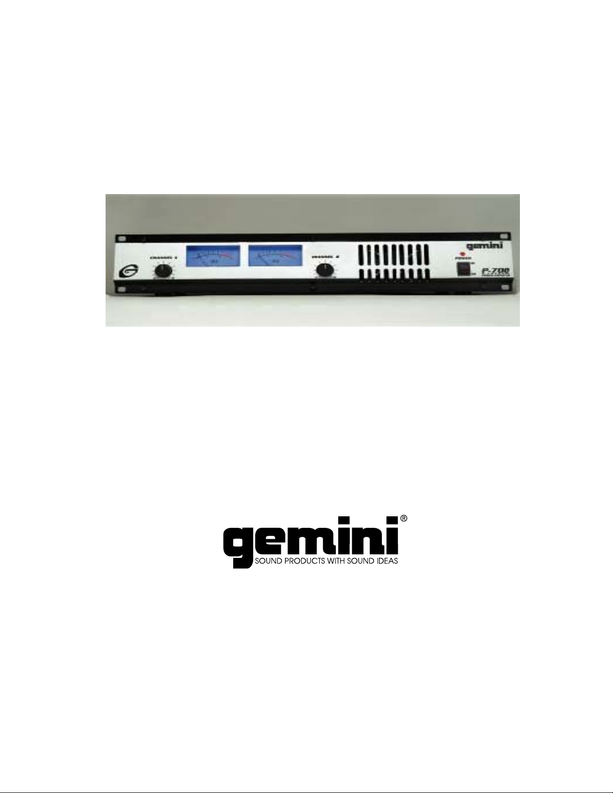
SERVICE MANUAL
P-700
PR PR
PR
PR PR
Features, Operating Instructions…………… .. Page 2
Specifications……………………………………. Page 4
Troubleshooting…………………………………. Page 5
Diagrams………………………………………….. Page 6
Parts List………………………………………….. Page 8
Schematics……………………………………….. Page 11
OFESSIONOFESSION
OFESSION
OFESSIONOFESSION
AL AL
AL
AL AL
AMPLIFIERAMPLIFIER
AMPLIFIER
AMPLIFIERAMPLIFIER
Page 2

introduction
Congratulations
P-700 Power Amplifier! You’ve made a really
wise choice because this state-of-the-art amplifier
has the latest features and technolo gy a nd is
backed by a three-year warranty! We know
you’re anxious to hook everything up and start
mixing beats and cranking up the volume on
those hot dance tracks, but we suggest reading
this instruction manual first as there are some
really cool features on this amplifier that we
wouldn’t want you to miss!
on purchasing this Gemini
features
State-of-the-art circuitry for the finest sound
•
quality and reliability
High output power to drive professional
•
speakers without clipping but also tame
enough for home use
Protection Circuitry (short circuit, thermal cut-
•
off, sub/ultrasonic freq uency fil ter s, tur n -on
delay, main fuse, secondary fuses)
Unbalanced stereo inputs with RCA type jacks
•
Ground lift switch for achieving the quietest
•
possible operation
Large blue-light illuminated VU meters to
•
give you greater control… and they look really
cool
Ultra-modern design with professional 19”
•
rack mounts.
Front-to-rear airflow with variable speed fan
•
control for maximum cooling and quietest
possible operation.
Variable speed fan for quieter operation with
•
softer music and home use.
Compact 2U well balanced enclosure
•
Steel reinforced chassis construction for
•
durability and longevity.
Common sense
Some of these things go without saying, but we’re
going to say them anyway!
Read all operating instructions before
•
using this equipment.
To reduce the risk of electrical shock,
•
do not open the unit. There are NO USER
REPLACEABLE PARTS INSIDE. For all repairs
or service questions please contact the Gemini
Service Department or your authorized dealer to
speak to a qualified Gemini Sound Products
technician.
Be sure to allow adequate front and
•
rear ventilation to avoid possible heat damage to
your equipment.
Be sure that AC power is OFF and all
•
level controls are set to MINIMUM before making
connections. This will eliminate any chance of
unexpected loud buzzes, pops or clicks that could
damage your speakers.
DO NOT EXPOSE THIS UNIT TO RAIN
•
OR MOISTURE.
Operators of electronic equipment should
•
never be in contact with water
Keep your power amplifier grounded for
•
maximum safety by always using a 3-prong plug.
If you are using an extension cord, always use a
3-prong cord as well.
DO NOT USE ANY SPRAY CLEANER OR
•
LUBRICANT ON ANY CONTROLS OR
SWITCHES.
Page 3

hook it up
Okay, let’s get connected!
REAR PANEL
Input Section:
Input Jacks
stereo RCA type jacks, with the tip of the jack
being positive (+) and the sleeve part being
negative (-)/ground.
Connect the output of your mixer here.
Output Section:
Disconnect unit from the AC power source before
making any connections. Pay close attention to
polarity when connecting your speakers.
(Connect the positive wire to the red terminal and
the negative wire to the black terminal).
Connecting your speakers using the wrong
polarity will not damage your speakers, but
will impact the quality of the sound (lack of bass
and incorrect stereo image).
Speaker Outputs
connectors are terminals that will accept a
standard banana plug, or bare wire.
Make sure that all the connections are clean
when using bare wire connections. If any strands
of wire from one connector touch the connector
next to it, the sound will distort, and your amplifier
will overheat.
✰
NOTE:
be lower than 4Ω (Ohm) per channel
AC Power Section:
Fuse
•
AC Inlet
•
the unit.
AC line voltage switch
•
amplifier for either 110-120 V or 220-240 V AC
lines.
Ground Lift Switch
•
from the chassis. (See the Ground Lift Switch
Instructions for more detail.)
(4):
Your amplifier has unbal ance d
(1)
the speaker output
(3):
Total speaker impedance must not
replace with proper type and rating.
is used to attach the power cord to
(6)
allows reconfiguring
(5)
is used to lift the ground
(2)
FRONT PANEL
Power Switch
•
Power LED
•
power is on. If the power LED does not light, refer
to the trouble-shooting guide.
Level Controls
•
each channel.
Large blue-light illuminated VU meters
•
display the output level of each channel.
Stereo Operation
The unit has two channels for stereo operation.
Each channel provides a separate signal at the
speaker outputs. The following instructions are
for use with 4Ω or 8Ω speakers of matched
power ratings.
1. With the power OFF, connect your input
cables to the Channel A and Channel B inputs
using the RCA INPUT JACKS
2. Connect your speakers to the Channel A and
Channel B SPEAKER OUTPUTS
speaker load must be at least 4Ω per channel.)
3. With the LEVEL CONTROLS
channels set to zero (fully counterclockwise), turn
the POWER SWITCH
playing some music and/or talking into your
microphone, and set the level of your input as
high as you think you’ll need it. This way it will be
as high above the amplifier’s noise floor as
possible so you’ll get the best possible sound
with the least amount of noise.
4. Now adjust your LEVEL CONTROLS for each
channel to your desired listening level. You also
have the choice of keeping the volume of both
speakers equal, or for certain situations you can
adjust the volume so one side will be louder than
the other.
turns the unit on and off.
(10):
the power LED lights when the
(9):
control the input levels for
(7):
operation
(1)
(3).
of both
(7)
ON. Okay, now try
(10)
(8)
(The total
Page 4

Using the Ground Lift Switch
Depending on how your sound system is hooked
up, sometimes applying the ground will create a
quieter signal path. Sometimes lifting the ground
can eliminate ground loops and that annoying
hum to give you quieter and cleaner overall
sound.
1. With the power amp ON, listen to the system in
idle mode (no music or signal) with the ground
ON. The GROUND LIFT SWITCH
will be in
(3)
the left position.
2. Turn the power OFF before moving the
GROUND LIFT SWITCH
Now lift the ground
(3).
by moving the GROUND LIFT SWITCH to the
right. Turn the power back ON and listen to
determine which position makes the overall
sound quieter with the least amount of noise and
hum.
✰
CAUTION
: DO NOT DISCONNECT THE AC
GROUND ON THE POWER AMPLIFIER IN ANY
WAY. THIS CAN BE VERY HAZARDOUS!!
Should you experience any difficulties or
problems, you can first refer to the
TROUBLESHOOTING GUIDE located on the
following page. If you still cannot fix the problem,
please call
Service.
1 (732) 738-9003 for Gemini Customer
That’s it !
Okay, that just about covers everything! NOW
you’re ready to grab a couple of great CD’s or
records, crank it up and get the party started!
specifications
Output Power EIA: 1kHz @ 1% THD, Wrms
Both Channels Driven 8Ω: ………….………………………………70
Both Channels Driven 4Ω: ………….………………………………90
Dynamic Headroom, dB:
At 8Ω:…………………………………………………………………1.5
At 4Ω:…………………………………………………………………3.3
Frequency Response:………………………………..30 Hz – 50 kHz
Total Harmonic Distortion: …………………………..less than 0.1%,
typical 0.05% at 1 kHz
Signal to Noise ratio:………………90 dB below rated power @ 8Ω
Damping factor: ……………………………..greater than 150 @ 8Ω
Slew rate:……………………………………………………….10 V/µS
Voltage gain, dB:……………………………………………………..27
Input Sensitivity (for rated power at 8Ω):…………….……….1Vrms
Input Impedance (unbalanced):...………………………………10 kΩ
Power consumption (at rated power at 4Ω,
both channels driven): ………………………………..……..…400 W
AC Power Requirements: ……………..….110-120 V or 220-240 V
60 / 50 Hz.
Indicators:……………………………………1VU-meter per Channel
1 Power LED
Cooling: ……………Variable Speed Fan, Front-to-Rear Forced Air
Protection: ……………………………Short Circuit, Thermal Cut-off,
Sub/Ultrasonic Frequency Filters,
Turn-on Delay, Main Fuse,
Secondary DC Fuses
Connectors:
Inputs:……………………………………………………….RCA Jacks
Speaker Outputs:……………………………………….Binding Posts
Dimensions:……………………………………..19”W x 11”D x 3.5”H
(483 x 280 x 89 mm)
Weight :……………………………………………..12.9 lbs (5.85 kg)
✰
Specifications and design are subject to
change without notice for purpose of
improvement
Page 5

troubleshooting
SYM PTO M
UNIT DO E S NOT PRODUCE SO UND.
POW ER L ED DO ES NOT LIGHT.
POW ER LED LIGHTS, B UT NO SOUND
IS PRO DUCED BY AM PLIFIER.
PO W ER SW ITCH NOT IN ON P OS ITION.
♦
PO W ER CAB LE N OT CONNECTED TO
♦
AM PLIFIER OR T O O U T L E T .
AC OUTLET NO T ACTIVE . ♦ REPLAC E AM PLIFIER MAIN PO W ER FUSE ON.
♦
M A I N A M PLI FI ER FU S E D EFEC TI V E.
♦
NO INPUT SO U RC E SIGNAL. ♦ CHECK F OR P ROPER FU N CT ION OF IN P U T
♦
INPUT SOURCE NOT CONNECTED. SOURCE DEVICE (M I XER, CD PLAYER, ET C .).
♦
DEFEC TIVE INPUT CONNECTING CABLE. ♦ CHECK INPUT CABLES & CONNECTIONS.
♦
SPEAK ERS NOT CONNECTED. ♦ REPLAC E CABLES IN QUESTION WITH KNOW N
♦
DEFEC TIVE SP EA K ER CABLES. GOOD CA BLES.
♦
SPEAK ER SYSTEM INOPERATIVE .
♦
AM PLIFIER’S LEV EL C O NTROLS ARE STA TUS OF SP EA KER SYSTEM .
♦
SET TO ZERO.
CAUSE
MOVE POW ER SW ITCH TO ON PO SITION.
♦
CONNECT PO W ER CABLE TO AC SUPPLY.
♦
CHECK CONDITION OF O UTLET.
♦
REA R PA N EL WITH CORRECT TYPE & RATING.
CHECK OPERATING CONDITION, CABLES AND
♦
BE SURE THE LEV EL CONTROLS ARE PROPERLY SET.
♦
SO LU TIO N
SOUND IS PRES ENT BUT VOLUM E IS
TOO LO W EV E N THO UG H SOURCE SET TOO LOW. INSTR UCTIONS.
DEVICE (i .e.: CD PLA YER, MIXER)
OUTPUT IS SET TO A HIGH LEV EL.
AM PLIFIER INP UT LEVEL CO NTRO LS ARE ♦ A DJUST LEVEL CONTROLS AS P ER
♦
LOUD 50/60 HZ OR 1 00/120 HZ HUM HE ARD ♦ IM PROPER OR D EF EC T IVE GR OUND
AT ALL TIMES THROUGH THE SPEAK ERS. C ONN EC TION AT INPUTS. PO W ER AM P AND ALL INPUT DEVICES.
IM PROPER OR DEFECTIVE GROUND
C ONN ECTION ON AC OUTLET. ♦ CHECK PO SITION OF GROUND LIFT SW ITC H
PO W ER AM PLIFIER. IF YO U ARE NOT
TO TALLY FA M ILIAR WITH GROUND LIFT ING
O R U N IF I CATION PROCEDURES, DO NOT
ATTEM PT THEM WITHO UT FIRST C O NSULT ING YO UR DE ALER OR A QUALIFIE D SO UN D
TECHNICIAN FO R M ORE IN F O R M A T I ON ON
GROUNDING. IM PROPERLY DONE, SUC H
PRO C ED UR ES CAN POSE A SAFETY AND/OR
FIRE HAZARD.
AT INP UT SOUR CE DEVIC E (S ). AND SIGNAL PROC ESSING AS WELL AS INP UT
IM PROPER OR D EF EC T IVE GROUND C ABLES TO PO W ER AM PLIFIER .
♦
GROUND LO O P TH RO UG H AC LINE AS PER INST RUCTIONS FO R LIFT ING THE
♦
CONNECTION / RACK M OUNTING . GRO UND.
CHECK F OR P ROPER AC LINE GROUND AT
♦
CHECK INPUT CABLES FO R ALL DEVICES
♦
NEV ER LIFT TH E AC LINE GROUND ON TH E
♦
SOUND IS DISTO RTED. ♦ DISTORTION OCCURRING IN SOURCE
DEVICE (C D PLAYER, MIXER, ETC .).
INPUT LEV EL IS SET TOO HIGH. INSTR UC TIONS.
♦
CHECK VU M ETERS
♦
A DJUST LEVEL CONTROLS AS PER
♦
FUSE BL OWS INTERM ITTENTLY.
ARE CORRECT.
SPEA KER LOAD IMPEDANCE IS TOO LO W .
♦
TYPE OR RAT ING OF THE FUS E IS N OT ♦ CHECK YO U R SPEA KER IMPEDANCE.
♦
CORRECT. ♦ CHECK THA T TH E FUS E TYP E AND RATING
CHECK FOR SHO RTS ON TH E O UTPUTS.
♦
em ail
For serv ic e -re lated questions you can em ail us at: se rv ice@ ge m inidj.co m
For te c h n ical support you can em ail us a t: techhelp@ ge m inidj.co m
Page 6

Page 7

B
9
7
6
4
5
8
3
8
7
2
3
1
10
Page 8

PARTS LIST
PART # QUANTITY NAME
1 012-037 1 PANEL CONTROL
2 021-467 1 MAIN CHASSIS
3 031-046 1 TOP COVER
4 041-430 1 HEAT SINK
5
6 003-111 2 KNOB ROTARY
(SMALL)
7 047-496 3 PCB SUPPORT
8 049-206 4 PAD FOOT
9
10 153-220 1 POLYFORM
11 196-137 3 SERIAL NO:LABEL
12 255-209 1 GIFT BOX
13 257-006 1 OWNER’S MANUAL
14 156-089 1 WARRANTY CARD
15
16 099-238 2 UK LABEL
17 099-232 2 LABEL-GREEN
18 099-233 2 LABEL-RED
19 099-234 2 LABEL-YELLOW
20
21 095-057 3 VDE LABEL
22 099-167 1 A LABEL
23 099-169 1 V LABEL
24 099-014 1 LABEL-MADE IN
TAIWAN
25 099-214 1 LABEL-MADE IN
CHINA
26 190-062 1 SILICON GEL
27 160-044 1 PE BAG 160×250mm
28 160-052 1 PE BAG 650×650mm
29 160-009 1 PE BAG 23×30cm
30
31 121-007A 14 BAND-HEAD TAP
PING SCREW
BTB-3 3×6(AB)
32 110-138 3 BAND-HEAD TAP
PING SCREW
BTS-2 3×8(B)
33 111-046A 2 BAND-HEAD TAP
PING SCREW
BTS-3 3×6(AB)
33 111-046A 2 BAND-HEAD TAP
PING SCREW
BTS-3 3×6(AB)
34 110-187A 2 BAND-HEAD TAP
PING SCREW/TWIN
SCREW 3×12(AB)
35 110-172A 1 BAND-HEAD TAP
PING SCREW/TWIN
SCREW
36 146-717 6 HEXAGON MACHINE
SCREW
37 111-060 1 PAN-HEAD TAPPING
SCREW PTS-3
4×8(N)
38 102-111 2 PAN-HEAD MACHINE
SCREW PMS
5×8(B)
39 107-022A 4 BAND-HEAD MA-
CHINE SCREW
M4×15(AB)
40 131-074 4 NUT (KNUT)4φ(B)
41 142-008 2 PLAIN WASHER4φ(Y)
42 143-008 2 SPRING
WASHER4φ(Y)
43 102-161 1 PAN-HEAD MACHINE
SCREW 3×12(Y)
44 131-081 1 NUT/WASHER 3φ(B)
45 102-068 2 PAN-HEAD MACHINE
SCREW
46
47 170-367 MASTER CARTON
48
49
50
1 262-352 1 PRINTED CIRCUIT
BOARD P-700-1
2 262-353 1 PRINTED CIRCUIT
BOARD P-700-2
3 262-354 2 PRINTED CIRCUIT
BOARD P-700-3
Page 9

5 074-189 2 INTEGRATED CIR-
CUIT TDA7294V
6
7 076-075 1 SILICON TRANSIS-
TORS 2SA1358
8 076-077 SILICON TRANSIS-
TORS OR 2SB631
9 076-074 1 SILICON TRANSIS-
TORS 2SC3421
10 076-076 SILICON TRANSIS-
TORS OR 2SD600
11 076-020 1 SILICON TRANSIS-
TORS 2SA733 (Q)(P)
12 076-023 SILICON TRANSIS-
TORS OR 2SA1015
(GR)(Y)
13
14 086-019 1 BRIDGE RECTIFIER
KBPC804W
15 087-027 2 VU METER
16
17 079-003 11 SILICON DIODE
1N4148
18 079-020 2 ZENER DIODE 1/2W
24V (RD24EB2)
19
20 080-086 1 LED (GREEN) 5φ
21
22 071-202 2 ROTARY VR 10KA
L:15MM
23 081-023 1 SLIDE SWITCH 2P2C
UL
24 081-030 1 SLIDE SWITCH
25 083-099 1 POWER SWITCH
26 001-613 1 DC FAN 24V
(80×80×25mm)
27
28 092-105 1 AC INLET
(IEC+FUSE)
29
30 100-072 2 FUSE 20mm VBS UTE
5A 250V
31 100-063 1 FUSE 20mm VBS UTE
4A 250V
32 100-064 1 FUSE 20mm VBS UTE
2A 250V
33
34 161-160 1 2P RCA JACK
35 161-172 1 4P SPEAKER TERMI-
NAL
36 161-109 4 FUSE CLIP JH-6
37
38 059-239 1 POWER TRANS-
FORMER EI-76×60
39 147-024 2 COIL 1.3µH 1.0φ×9φ×
9 1/2T
40
41 093-370 1 AC CORD SVT AWG
18×3C VW-1 UL
42 093-371 1 AC CORD 220V VDE
43 093-410 1 AC CORD ARGEN-
TINA
44 093-369 1 AC CORD 230V BS
45
46 061-102 2 METAL FILM RESIS-
TORS 2W 8.2Ω
47 060-842 2 CARBON FILM RE-
SISTORS 1/2W 22KΩ
48 060-240 1 CARBON FILM RE-
SISTORS 1/4W 82 Ω
49 060-250 2 CARBON FILM RE-
SISTORS 1/4W 220 Ω
50 060-263 4 CARBON FILM RE-
SISTORS 1/4W 750 Ω
51 060-279 3 CARBON FILM RE-
SISTORS 1/4W 2.2KΩ
52 060-288 13 CARBON FILM RE-
SISTORS 1/4W 5.1KΩ
53 060-293 3 CARBON FILM RE-
SISTORS 1/4W 8.2KΩ
54 060-303 5 CARBON FILM RE-
SISTORS 1/4W 22KΩ
55 060-351 1 CARBON FILM RE-
SISTORS 1/4W 1MΩ
56
57 050-153 2 ELECTROLYTIC
CAPACITORS N.P
10µ/50V
58 050-162 1 ELECTROLYTIC
CAPACITORS
10µ/50V
59 050-121 7 ELECTROLYTIC
CAPACITORS
22µ/50V
Page 10

62
63 051-010 2 CERAMIC CAPACI-
TOR 10P/50V
64 051-048 2 CERAMIC CAPACI-
TOR 390P/50V
65 051-156 1 CERAMIC CAPACI-
TOR UL 0.0047µ/400V
66
67 054-022 1 POLYESTER CE-
RAMIC CAPACITOR
0.047µ/50V
82
83 209-004 1 LEAD WIRE (WHITE)
UL1015#18AWG 6×6
310mm
84 202-110 1 LEAD WIRE (RED)
UL1015#18AWG 6×6
310mm
85 200-096 1 LEAD WIRE (BLACK)
UL1007#24AWG 9×9
150mm
86
87 060-703 4 JUMPER WIRE 0.7φ
T/52mm P=10mm
88 060-703 5 JUMPER WIRE 0.7φ
T/52mm P=15mm
89 060-703 1 JUMPER WIRE 0.7φ
T/52mm P=20mm
90
91 146-509 4 PIN CONNECTOR
92
93 190-075 1 HEAT-SHRINK TUB
ING UL 28φ 35mm
94 190-230 2 HEAT-SHRINK TUB
ING UL 35φ 35mm
95 190-063 2 TUBE 1φ5mm
96 190-063 2 TUBE 1φ 10mm
97
98 003-605 3 CABLE TIES CV-100
Page 11

D
C
B
A
RevDWG No.
+
M1
1
Y2
X2
1
1N4148
D6
R5
R3
D4
C24
42 13
FAN1
R21
5.1K
R26
5.1K
R29
A
Left ch. OUTPUT
22K
-E
TDA7294V
R19
24V 0.13A
2
1
Y11
X11
2
1
2SA1358
Q1
C9
2SA1015
Q3
2.2K
R13
5.1K
R11
1N4148
D3
R12
5.1K
R10
+E
5.1K
R35
22uF25V
C14
5.1K
R23
8.2K
100uF25V
T
D13
1N4148
82
R30
22K
ZD2
24V 0.5W
22K
R12
10pF
C21
5.1K
R27
10uF25V
C12
R17
8.2K
8.2K
R18
X8B
1
2
1N4148
D11
1N4148
D12
0.1uF100V
C25
R37
8R2 1W
1.0uH
L2
22uF50V
C22
0.1
C15
+E
14
13
6
7
15
8
-Vs
+Vs
OUT
BOOTSTRAP
MUTE
IN+MUTE
IN +9STBY
4
3
10
22K
R28
22uF25V
C16
390pF
C23
-PWVs
STBY-GND
1
+PWVs
22K
R32
IN -
U2
2
750
R34
432
432
B
1N4148
D8
750
220
R4
X8A
4
5.1K
22uF50V
C4
1N4148
2.2K
R14
10pF
22K
R31
3
1N4148
D10
0.1uF100V
C10
R22
1.0uH
L1
8R2 1W
C17
22uF50V
+E
14
13
6
7
15
8
-Vs
+Vs
OUT
-PWVs
+PWVs
BOOTSTRAP
MUTE
IN -
IN+MUTE
IN +9STBY
U1
2
750
R33
STBY-GND
1
4
3
10
C18
22uF25V
390pF
C19
22K
R25
0.1
C20
1N4148
D2
Right ch. OUTPUT
1N4148
D1
-E
TDA7294V
M2
Y3
X3
"Ground lift"
0.15
C13
C1
SW1
10uF25V NP
2 3 4
MAIN PCB
5.1K
R15
X1
Left ch. INPUT
1M
R9
0.047
C8
Y7
X7
GRN
C3
J1
Right ch. INPUT
GRN
10uF25V NP
5.1K
R16
0.15
C5
2
1
X5
X9
+
42 13
432
1
432
1
POWER AMPLIFIER P-6
B
+24V
750
R1
220
R2
5.1K
R6
22uF50V
C2
2.2K
R7
+24V
24V 0.5W
ZD1
5.1K
R8
2SC3421
Q2
+E
5A
F1
4700uF50V
C6
4
KBPS08-02
REC1
3
5.1K
R38
2
X10
Y1
Y2
RED
C7
D5
4700uF50V
1N4148
-E
5A
F2
A
1
REDX6BLKX4RED
REDY3BLK
Gemini Sound Products Corp.
FCSM No.
Size
Orcad D
0 of 0
SheetScale
4321
Y1
321
2
3
1
10K
RV3
Left ch. GAIN
1
D
2
1
RV3
C
Y5
321
3
10K
Right ch. GAIN
Y9
P3
POWER PCB
2
1
6
T1
5
BRN
P4
P5
GRN
LD1
"POWER"
SW2
SW-POWER
P1
B
C101
BLU
P2
FUSE
4A 115V / 2A 230V
7
3
4
F
ORG
SW3
VOLTAGE SELECTOR
NEL
8
1
2
BLK
WHT
115v 230v
AC INLET
A
Page 12

In the USA: If you experience problems with this unit,
call 1-732-738-9003 for Gemini Customer Service.
Do not attempt to return this equipment to your dealer.
Parts of the design of this product may be protected by worldwide patents.
Information in this manual is subject to change without notice and does
not represent a commitment on the part of the vendor. Gemini Sound
Products Corp. shall not be liable for any loss or damage whatsoever
arising from the use of information or any error contained in this manual.
No part of this manual may be reproduced, stored in a retrieval system or
transmitted, in any form or by any means, electronic, electrical,
mechanical, optical, chemical, including photocopying and recording, for
any purpose without the express written permission of Gemini Sound
Products Corp.
It is recommended that all maintenance and service on this product is
performed by Gemini Sound Products Corp. or its authorized agents.
Gemini Sound Products Corp. will not accept liability for loss or damage
caused by maintenance or repair performed by unauthorized personnel.
Worldwide Headquarters • 120 Clover Place, Edison, NJ 08837 • USA
Tel: (732) 738-9003 • Fax: (732) 738-9006
France • G.S.L. France • 11, Avenue Leon Harmel, Z.I. Antony, 92160 Antony, France
Germany • Gemini Sound Products GmbH • Ottostrasse 6, 85757 Karlsfeld, Germany
UK • Gemini Sound Products • Unit C4 Hazleton Industrial Estate, Waterlooville, UK P08 9JU
Spain • Gemini Sound Products S.A. • Rosello, 516, Barcelona, Spain, 08026
© Gemini Sound Products Corp. 2002 All Rights Reserved
Tel: + 33 (0) 1 55 59 04 70 • Fax: + 33 (0) 1 55 59 04 80
Tel: 08131 - 39171-0 • Fax: 08131 - 39171-9
Tel: 087 087 00880 • Fax: 087 087 00990
Tel: 349-3435-0814 • Fax: 3493-347-6961
 Loading...