

Page 1

OPERA TIONS MANUAL
Bedienungsanleltung
Manual de funcionamiento
Manual de fonctionnement
Manual del utente
KL-10
PROFESSIONAL STEREO PREAMP MIXER
Professionneller Stereo V orverstärkermischpult
Mezclador-preamplificador estereofónico para el profesional
Mélangeur-préamplificateur stéréophonique pour le
professionnel
Miscelatore-preamplificatore stereofonico per il professionale
Page 1
Page 2
3
12 13
32
31
2
5
10
10
4
11
11
25
1
26
6
28
7
27
14
8
15
30
29
16
23
24
20
17
18
16
19
21 22 20 21 22
Page 2
17
18
23
24
9
Page 3
Page 3
45
LIFT
46
34
34
33
35
35
36
36
37
37
38
38
39
39
40
40
43
41
41
42
42
44
Page 4

Introduction
Congratulations on purchasing the Gemini KL-10 mixer. This state of the
art mixer is backed by a three year warranty, excluding crossfader and
channel slides. Prior to use, we suggest that you carefully read all the
instructions.
Features
• Kill Feature for Bass, Mid and High of each channel
• 2 Stereo channels
• 2 Phono/Line Convertible, 2 Line and 1 Mic inputs
• Combo XLR or 1/4" DJ Mic jack
• Low, Mid, High, Gain and Balance controls on each channel
• Punch In and Punch Out for each channel
• Loop
• Master, Booth and Record outputs
• Dual mode display
Cautions
1. All operating instructions should be read before using this
equipment.
2. To reduce the risk of electrical shock, do not open the unit. There are
NO USER REPLACEABLE PARTS INSIDE. Please refer servicing to a
qualified service technician.
In the U.S.A., if you have any problems with this unit,
call 1-732-738-9003 for customer service. Do not return
equipment to your dealer.
3. Do not expose this unit to direct sunlight or to a heat source such as
a radiator or stove.
4. This unit should be cleaned only with a damp cloth. Avoid solvents
or other cleaning detergents.
5. When moving this equipment, it should be placed in its original carton
and packaging. This will reduce the risk of damage during transit.
6. DO NOT EXPOSE THIS UNIT TO RAIN OR MOISTURE.
7. DO NOT USE ANY SPRAY CLEANER OR LUBRICANT ON ANY
CONTROLS OR SWITCHES.
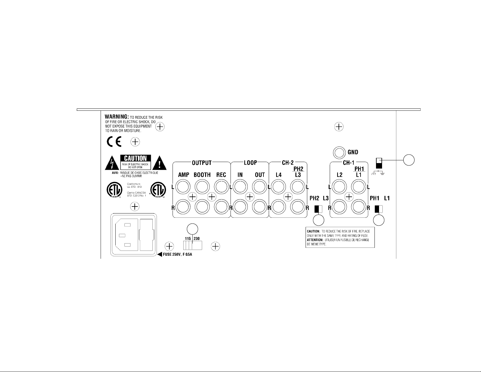
Connections
1. Before plugging in the power cord, make sure that the VOLTAGE
SELECTOR (33) switch is set to the correct voltage.
2. Make sure that the POWER (1) switch is in the off position. The
POWER LED (2) will be off.
3. The KL-10 is supplied with 3 sets of output jacks. The OUTPUT
AMP (34) jacks are used to connect to your main amplifier. The
OUTPUT REC (36) jacks can be used to connect the mixer to the
record input of your recorder enabling you to record your mix. The
OUTPUT BOOTH (35) jacks allow you to hook up an additional
amplifier.
4. The DJ MIC (3) input (found on the front panel) accepts a 1/4" or
XLR connector and balanced and unbalanced microphones.
5. On the rear panel are 2 stereo PHONO/LINE (40, 42) inputs and 2
stereo LINE (39, 41) inputs. The PHONO/LINE SWITCHES (43, 44)
enable you to set the (40, 42) inputs to Phono or Line. The phono
inputs will accept only turntables with a magnetic cartridge. A
GROUND SCREW (45) for you to ground your turntables is located
on the rear panel. The stereo line inputs will accept any line level
input such as a CD player, a cassette player, etc.
6. Headphones can be plugged into the front panel mounted
HEADPHONE (9) jack.
7. There are LOOP INPUTS (37) and LOOP OUTPUTS (38) located on
the rear panel. If you are using an outboard signal enhancer, you
can use the LOOP OUTPUTS (38) to send the signal to the device
and the LOOP INPUTS (37) to bring the signal back in to the mixer.
The unit comes with jumpers to be used with the loop inputs and
outputs. Keep the jumpers in the unit if you are not using the loop to
prevent interruptions in your music program by the accidental
touching of the loop button.
Using the Ground Lift Switch
Depending on your system configuration, sometimes applying the
ground will create a quieter signal path. Sometimes lifting the ground
can eliminate ground loops and hum to create a quieter signal path.
1. With the mixer on, listen to the system in idle mode (no signal
present) with the ground applied (the GROUND LIFT SWITCH (46) in
the bottom position).
2. Then turn the power off before moving the GROUND LIFT
SWITCH (46). Lift the ground by moving the GROUND LIFT SWITCH
to the top position, turn the power back on and listen to determine
which position will provide a signal devoid of background noise and
hum. Keep the GROUND LIFT SWITCH in the ground position if the
noise level remains the same in either position.
CAUTION: DO NOT TERMINATE THE AC GROUND ON THE POWER MIXER
IN ANY WA Y. TERMINA TION OF THE AC GROUND CAN BE
HAZARDOUS.
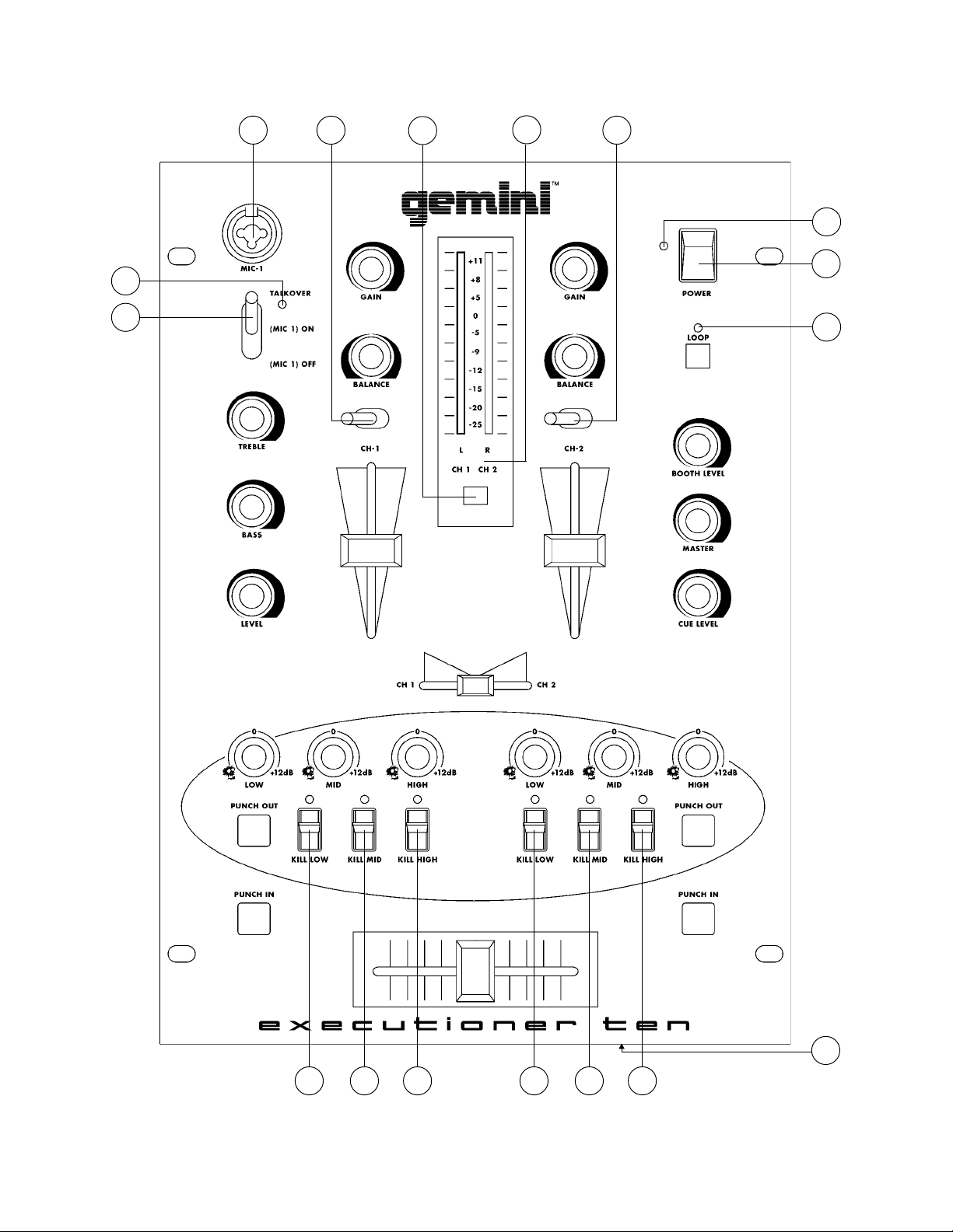
Operation
1. POWER ON: Once you have made all the equipment connections to
your mixer, press the POWER SWITCH (1). The power will turn on
and the POWER LED (2) will glow RED.
2. CHANNEL I: The GAIN (10), BALANCE (11), HIGH (18), MID (17),
and LOW (16) controls allow you to fully adjust the selected source.
Switch # (12) allows you to select either the PHONO 1/LINE 1 (42)
or the LINE 2 (41) input. The CHANNEL SLIDE (14) controls the
output level of this channel.
3. CHANNEL II: The GAIN (10), BALANCE (11), HIGH (18), MID (17),
and LOW (16) controls allow you to fully adjust the selected source.
Switch # (13) allows you to select either the PHONO 2/LINE 3 (40)
or the LINE 4 (39) input. The CHANNEL SLIDE (15) controls the
output level of this channel.
4. CROSSFADER SECTION: The CROSSFADER (19) allows the mixing
of one source into another. The left side of the CROSSFADER (19) is
channel I and the right side is channel II. The CROSSFADER (19) in
your unit is removable and if the need arises can be easily replaced.
Crossfader units are available in three varieties. Part # RF-45 (which
is identical to the crossfader supplied with the mixer) has a 45 mm
travel from side to side. Part # RF-30 is available with a 30 mm travel
distance. Also available is the PSF-45 with a special curve designed
for scratch mixing. Just purchase one of these crossfader units
from your Gemini dealer and follow these instructions:
Page 4
Page 5
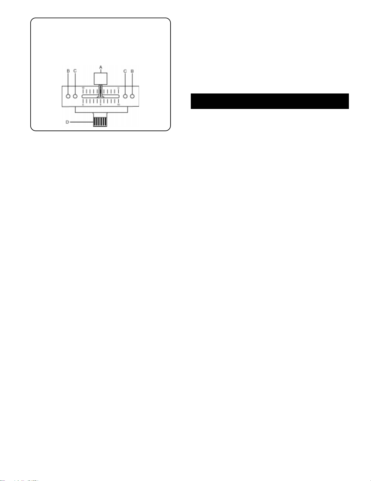
1. Unscrew the outside FADER PLA TE SCREWS (B). Do not
touch the INSIDE SCREWS (C).
2. Carefully lift the fader and unplug the CABLE (D).
3. Plug the new fader into the cable and place it back in the
mixer.
4. Screw the fader to the mixer.
5. KILLING FREQUENCIES: There are two ways to kill frequencies,
using the LOW, MID and HIGH KILL SWITCHES (20, 21, 22) and
using the LOW, MID and HIGH ROTARY CONTROLS (16, 17, 18).
When the selected KILL SWITCH is activated the LED will light and
the frequency will be killed. When the selected ROTARY CONTROL
is turned all the way to the left, the frequency will be killed. You can
also use the ROTARY CONTROLS to boost frequencies up to +12
dB. The normal setting for the ROTARY CONTROLS is zero.
SUGGESTION: You can use the Kill Features on each channel to
remove Low, Mid and/or High bands for a smoother mix and mix
frequencies from both channels to create special effects.
6. PUNCH IN: The PUNCH IN BUTTON (23) allows you to add a
channel’s signal to the mix when the crossfader is set to the
opposite channel.
7. PUNCH OUT: The PUNCH OUT BUTTON (24) allows you to remove a
channel’s signal from the mix when the crossfader is set to that
channel.
SUGGESTION: Keep the crossfader in the center and use the
punch in and punch out of both channels together to create
scratch type effects.
8. LOOP SECTION: T o activate loop, press the LOOP BUTTON (25) and
the LOOP LED (26) will light. When the LOOP LED is lit, any device
connected to the LOOP OUTPUT (38) and INPUT (37) jacks will be
inserted into the signal path.
9. OUTPUT CONTROL SECTION: The level of the AMP OUT (34) is
controlled by the MASTER (27) control. The BOOTH (28) control
adjusts the level of the BOOTH OUTPUT (35). HINT: The booth
OUTPUT is used by some DJs to run monitor speakers in their DJ
booth. You can also use it as a second ZONE or AMP output.
NOTE: The RECORD OUT (36) has no level control.
The level is set by the channel slides and the gain
controls of the selected channel. The tonal qualities are
set by the bass, treble and mid controls of that same
channel.
10. TALKOVER SECTION: The purpose of the talkover section is to allow
the program playing to be muted so that the mic can be heard above
the music. The MIC/TALKOVER SWITCH (4) has three settings.
When the MIC/TALKOVER SWITCH (4) is in the bottom position, the
mic and talkover are both off. When the MIC/TALKOVER SWITCH
(4) is in the center position the mic is on, the MIC INDICATOR (5) will
glow, but talkover is off. When the MIC/TALKOVER SWITCH (4) is
in the top position, the mic and talkover will be on and the volume of
all sources except the Mic input are lowered by 16 dB. The TREBLE
(6), BASS (7), and LEVEL (8) controls allow you to fully adjust the
mic signal.
11. CUE SECTION: By connecting a set of headphones to the
HEADPHONE (9) jack, you can monitor either channel or both. Select
the Channel I by sliding the CUE SLIDER (29) control to the left or
Channel II by sliding the CUE SLIDER (29) control to the right. Use
the CUE LEVEL (30) control to adjust the headphone volume without
effecting the overall mix.
Page 5
12.DISPLAY: The dual function DISPLAY (31) indicates either the
MASTER OUTPUT (34) left and right levels or the channel I and
channel II levels. You can choose the option you want by pressing
the DISPLAY (32) button.
NOTE: When the DISPLAY (31) is in the channel I/
channel II display mode, by adjusting the individual
channel gain and tone controls, you can increase or
decrease the signal to match the other channels signal.
The channel slides and crossfader have no effect on the
display readings.
Specifications
INPUTS:
DJ Mic....................................................1.5mV 2Kohm balanced
Phono.........................................................................3mV 47Kohm
Line.......................................................................150 mV 27Kohm
OUTPUTS:
Amp/Booth......................................................0 dB 1V 400ohm
Max..............................24V Peak to Peak
Rec...........................................................................225mV 5Kohm
MIC:
Bass......................................................................................± 12dB
High.......................................................................................± 12dB
GENERAL:
Bass (Channels I - II)........................................................+ 12dB/Kill
Mid (Channels I - II).........................................................+ 12dB/Kill
Treble (Channels I - II).....................................................+ 12dB/Kill
Gain (Channels I - II)...........................................................0 to -20dB
Frequency Response....................................20Hz - 20KHz +/- 2dB
Distortion................................................................................0.02%
S/N Ratio...............................................................better than 80dB
Talkover Attenuation..............................................................-16dB
Headphone Impedance.........................................................16ohm
Power Source.............................................115/230V 50/60Hz 10W
Dimensions...........................................10”w x 4 5/8”h x 14”d
Weight........................................................................8.3 lbs.
Page 6

Einleitung
Wir gratulieren Ihnen zum Kauf eines Gemini KL-10 Mischpults. Dieses
moderne Mischpult enthält dreijährige Garantie, ausscheließlich
crossfader und Kanalschieber. Vor Anwendung dieses Mischpults bitte
alle Anweisungen sorgfältig durchlesen.
Funktionen
• Beseitigung der Low-, Mid- und High-Frequenzen in jedem Kanal
• 2 Stereokanäle
• 2 konvertierbare Eingänge für Phonoleitungen/Leitung, Eingänge für
2 Leitungen, Eingang für 1 Mikrophon
• Buchse für DJ Mikrophon: XLR oder 1/4"
• Tief, Mittel, Hoch, Tonstärken- und Balanceregler für jeden Kanal
• Punch In und Punch Out für jeden Kanal
• Regelkreis
• Master Ausgang und Ausgänge für Kabine und Aufnahme
• Doppelte Tonartanzeige
Vorsichtsmaßnahmen
1. Vor Anwendung dieses Geräts bitte alle Anweisungen sorgfältig
durchlesen.
2. Das Gerät nicht öffnen, um das Risiko elektrischen Schocks zu
vermeiden. Es enthält KEINE VOM ANWENDER ERSETZBAREN TEILE.
Die Wartung darf nur von befähigten Wartungstechnikern
durchgeführt werden.
3. Das Gerät von direktem Sonnenlicht oder einer Wärmequelle wie
Heizkörper oder Ofen aussetzen.
4. Dieses Gerät darf nur mit einem feuchten Tuch gesäubert werden.
Keine Lösungs- oder Reinigungsmittel benutzen.
5. Bei Umzügen sollte das Gerät in seinem ursprünglichen
Versandkarton und Verpackungsmaterial verpackt werden. Dadurch
verhindert man, daß das Gerät während des Transportes
beschädigt wird.
6. DIESES GERÄT NICHT REGEN ODER FEUCHTIGKEIT AUSSETZEN.
7. AN DEN REGLERN ODER SCHALTERN KEIN SPRAYREINIGUNGSMITTEL ODER SCHMIERMITTEL BENUTZEN.
5. An der Rückwand sind jeweils 2 Stereoeingänge PHONO/LINE
(40,42), 2 Stereoeingänge LINE (39,41) angebracht. Die Schalter
PHONO/LINE (43,44) ermöglichen Ihnen, die Eingänge (40,42) an
Phono oder Line anzuschließen. Die Phono-Eingänge werden nur
Plattenspieler mit einem magnetischem T onabnehmer aufnehmen.
Eine Erdungschraube GROUND (45) zur Erdung des Plattenspielers
ist an der Rückwand angebracht. Die Stereo-Leitungseingängen
nehmen Geräte wie CD- oder Kassettenspieler auf.
6. Kopfhörer können an der an der Vorderwand montierten KopfhörerBuchse HEADPHONE (9) eingesteckt werden.
7. Die LOOP INPUTS (37) (Regelkreiseingänge) und die LOOP
OUTPUTS (38) (Regelkreisausgänge) sind an der Rückwand
angebracht. Falls Sie Ausgangssignalanreicherung benutzen,
können Sie die LOOP OUTPUTS (38) benutzen, um das Signal zum
Gerät zu senden, und die LOOP INPUTS (37) benutzen, um zum
Mischpult zurückzusignalisieren. Dieses Gerät wird mit Jumpers
geliefert, die mit den Regelkreiseingängen und -ausgängen zu
benutzen sind. Wenn Sie den Regelkreis nicht benutzen, sollten die
Jumpers im Gerät bleiben, um Unterbrechungen im Abspielprogramm
durch versehentliches Berühren der Regelkreistaste zu verhindern.
Benutzung des Masse-Trennschalters
Abhängig von Ihrer Systemkonfiguration, wenn man hin und wieder
Masse anlegt, kann man damit einen ruhigeren Signalpfad schaffen.
Wenn man hin und wieder die Masse trennt, kann man dadurch
Massekreise und Brummen eliminieren, um einen ruhigeren Signalpfad
schaffen.
1. Wenn das Mischpult eingeschaltet ist, das System im Ruhemodus
(ohne Signal) bei angelegter Masse abhorchen (der Masse-
Trennschalter - GROUND LIFT SWITCH (46) ist nach unten
geschalt).
2. Dann den Leistungsschalter ausschalten bevor der Masse-
Trennschalter - GROUND LIFT SWITCH (46) betätigt wird. Den
Masse-Trennschalter nach oben legen, die Leistung wieder
einschalten und horchen, um zu bestimmen, welche Position ein
Signal ohne Grundgeräusch und Brummen erzeugt. Den MasseTrennschalter in Masseposition halten, falls der Geräuschpegel in
beiden Position unverändert bleibt.
VORSICHT : DIE MASSE IN KEINER WEISE AM MISCHPUL T
ABSCHLIESSEN. DER ENDABSCHLUSS DER MASSE KANN MIT
GEFAHREN VERBUNDEN SEIN.
Bedienung
Anschlüsse
1. Bevor Sie das Stromkabel anschließen, darauf achten, daß der
VOLTAGE SELECTOR (33) (Spannungswähler) auf die richtige
Spannung einstellt ist.
2. Darauf achten, daß der Spannungsschalter POWER (1) in OffPosition geschaltet ist. Die POWER LED (2) wird ausgeschaltet sein.
3. Der KL-10 verfügt über 3 Ausgangsbuchsenpaare. Die Buchsen
OUTPUT AMP (34) dienen zum Anschluß an den Hauptverstärker.
Die Buchsen OUTPUT REC (36) können dazu dienen, das Mischpult
an den Aufnahmeeingang des Aufnahmegerätes anzuschließen, um
die Tonmischung aufnehmen zu können. Die Buchsen OUTPUT
BOOTH (35) ermöglichen Anschluß an einen zusätzlichen
Verstärker.
4. Der Eingang DJ MIC (3) (an der Vorderseite) nimmt Anschlüsse mit
Durchmesser von 0,38 mm (1/4") oder XLR auf, und balancierte und
unbalancierte Mikrophone auf.
1. STROM EIN: Nachdem Sie das Gerät am Mischpult angeschlossen
haben, drücken Sie auf die Taste POWER (1). Der Strom wird
eingeschaltet und die POWER LED (2) erleuchtet ROT .
2. KANAL I: Die Regelelemente GAIN (10), BALANCE (11), HIGH (18),
MID (17) und LOW (16) ermöglichen ein vollkommenes Regulieren
der ausgewählten Tonquelle. Schalter # (12) ermöglicht, den Eingang
von PHONO 1/LINE 1 (42) oder LINE 2 (41) auszuwählen.
CHANNEL SLIDE (14) regelt den Ausgangstonsignal dieses Kanals.
3. KANAL II: Die Regelelemente GAIN (10), BALANCE (11), HIGH (18),
MID (17) und LOW (16) ermöglichen ein vollkommenes Regulieren
der ausgewählten Tonquelle. Schalter # (13) ermöglicht, den Eingang
von PHONO 2/LINE 3 (40) oder LINE 4 (39) auszuwählen.
CHANNEL SLIDE (15) regelt den Ausgangstonsignal dieses Kanals.
4. ÜBERBLENDER: Der Überblender CROSSFADER (19) ermöglicht das
Mischen von Tonquellen. Links des CROSSFADER (19) ist Kanal I
und die rechte ist Kanal II. Der CROSSFADER (19) Ihres Geräts kann
entfernt werden und läßt sich bei Bedarf leicht ersetzen.
Überblender sind in drei Größen verfügbar. Teile-Nr. RF-45 (die mit
dem Überblender Ihres Geräts identisch ist) hat eine
Seitenverschiebbarkeit von 45 mm. Gleichfalls ist Teile-Nr. 30 mit
einer Verschiebbarkeit von 30 mm verfügbar. Ebenfalls ist Teile-Nr.
Page 6
Page 7

PSF-45 mit einer Spezialkrümmung für Raspelmischen verfügbar. Sie
können einen dieser Überblender bei Ihrem Gemini-Händler beziehen
und diese Anweisungen befolgen.
1. Die äußeren SCHRAUBEN DER ÜBERBLENDERPLATTE
(B) losschrauben. Nicht die INNENSCHRAUBEN (C)
losschrauben.
2. Den Überblender vorsichtig anheben und das KABEL (D)
herausziehen.
3. Den neuen Überblender in das Kabel hineinfügen und
wieder in das Mischpult setzen.
4. Den neuen Überblender mit den Schrauben am Mischpult
befestigen.
5. BESEITIGUNG VON FREQUENZEN: Es gibt zwei Möglichkeiten,
Frequenzen zu beseitigen, indem man die Schalter LOW, MID und
HIGH (20,21,22) drückt, wobei man die Drehschalter LOW, MID und
HIGH (16,17,18) benutzt. Wenn der ausgewählte KILL SWITCH
aktiviert ist, erleuchtet die LED, und die Frequenz wird beseitigt.
Wenn der ausgewählte ROTARY SWITCH ganz nach links
durchgedreht wird, wird die Frequenz beseitigt. Die Drehschalter
können ebenfalls benutzt werden, um die Frequenzen bis auf +12
dB anzuheben. Die normale Einstellung für Drehschalter ist Null.
EMPFEHLUNG: Sie können die Kill-Features mit jedem Kanal
benutzen, um die Frequenzbänder Low, Mid und High zwecks
Erzeugung einer glatteren Frequenzmischung zu entfernen, und um
Frequenzen von beiden Kanälen zu mischen, um Spezialeffekte zu
erzielen.
6. PUNCH IN: Die T aste PUNCH IN (23) ermöglicht Ihnen, ein Signal
eines Kanals dem Tongemisch hinzuzufügen, wenn der Überblender
auf den gegenüberleigenden Kanal eingestellt ist.
7. PUNCH OUT : Die Taste PUNCH OUT (24) ermöglicht Ihnen, ein Signal
eines Kanals vom Tongemisch zu entfernen, wenn der Überblender
auf diesen Kanal eingestellt ist.
EMPFEHLUNG: Sie können den Überblender in der Mitte halten, und
wenn beide Kanäle gleichzeitig ein- und ausgedrückt werden, erzielt
dies eine Art Raspelgeräusch.
8. REGELKREIS: Um einen Regelkreis zu aktivieren, müssen Sie die
T aste LOOP (25) drücken, und die LOOP LED (26) erleuchtet. Wenn
die LOOP LED erleuchtet ist, wird jedes Gerät, das an den Buchsen
LOOP OUTPUT (38) und LOOP INPUT (37) angeschlossen ist, in
den Signalweg eingeführt.
9. AUSGANGSREGELUNG. Der Verstärkerausgangspegel AMP OUT
(34) wird vom Schieberegler MASTER (27) geregelt. Der Regler
BOOTH (28) justiert den Pegel des BOOTH OUTPUT (35).
EMPFEHLUNG: Die Kabinenausgang wird von einigen DJs benutzt,
um die Lautsprecher in der DJ-Kabine zu überwachen. Ebenfalls
kann es als zweiter ZONE - oder AMP-Ausgang benutzt werden.
HINWEIS: RECORD OUT (36) enthält keine
Tonstärkenregelung. Die Tonstärke wird durch KanalSchiebevorrichtungen und die Tonstärkenregler des
ausgewählten Kanals eingestellt. Die Tonqualität wird
durch die Tiefen-, Höhen, und Mittelbereichsregler dieses
Kanals eingestellt.
10. TALKOVER: Durch die Talkover-Funktion wird das abgespielte
Programm gedämpft, um eine Ansage über das Mikrophon hören zu
können. Der Schalter MIC/TALKOVER (4) hat drei Einstellungen.
Wenn der Schalter MIC/TALKOVER (4) in der unteren Position steht,
sind MIC I und Talkover beide ausgeschaltet. Steht der Schalter MIC/
TALKOVER (4) in der mittleren Position, ist MIC I eingeschaltet. Der
MIC-Anzeiger (5) ist erleuchtet, jedoch ist Talkover ausgeschaltet.
Wenn der Schalter MIC/TALKOVER (4) in der oberen Position steht,
sind MIC I und Talkover eingeschaltet, und Lautstärken aller
Tonquellen, außer des MIC-Eingangs, werden um 16 dB reduziert.
Die Regler TREBLE (6), BASS (7) und LEVEL (8) ermöglichen Ihnen,
den Mikrofontonstärke zu regulieren.
1 1. CUE: Indem Sie die Kopfhörer an der Buchse KOPFHÖRER (9)
anschließen, können Sie einen oder alle Kanäle überwachen.
Wählen die Kanal I aus, indem Sie den Regler CUE SLIDER (29) nach
links schieben, oder Kanals II auswählen, indem Sie den Regler CUE
SLIDER (29) nach rechts schieben. Betätigen Sie die Taste CUE
LEVEL (30), um die Tonstärke des Kopfhörers zu regulieren ohne
Einfluß auf die Mischung.
12. ANZEIGE: Das Zweifunktionsanzeige DISPLAY (31) zeigt entweder
die linken und rechten Pegel des MASTER OUTPUT (34) von Kanal I
und Kanal II. Sie können die gewünschte Option auswählen, indem
Sie DISPLAY (32) drücken.
HINWEIS: Wenn DISPLAY (31) der Anzeigemodus von
Kanal I/Kanal II ist, können Sie, indem Sie die
individuellen Kanal-Tonstärkenregelungen justieren, das
Signal erhöhen oder mindern, um es dem Signal des
anderen Kanals anzupassen. Der Kanalschieber und der
Überblender haben keinen Einfluß auf die Anzeige.
Spezifikationen
EINGÄNGE:
DJ-Mikrophon....................................1,5 mV, 2 K-Ohm unbalanced
Phono....................................................................3 mV, 47 K-Ohm
Leitung..............................................................150 mV, 27 K-Ohm
AUSGÄNGE:
Amp/Kabine.......................................................0 dB 1 V 400 Ohm
max.............................24 V Spitze-Spitze
Aufnahme.............................................................225 mV 5 K-Ohm
MIKROFONE:
Tiefe....................................................................................± 12 dB
Hoch....................................................................................± 12 dB
ALLGEMEINES:
Tiefenregler (Kanäle I - II)..............................................+ 12 dB/Kill
Mittenregler (Kanäle I - II)..............................................+ 12 dB/Kill
Höhenregler (Kanäle I - II)..............................................+ 12 dB/Kill
Tonstärkenregler (Kanäle I - II).....................................0 bis -20 dB
Frequenzgang..........................................20 Hz - 200 KHz +/- 2 dB
Klirrfaktor...............................................................................0,02%
Störabstand...........................................................besser als 80 dB
Talkover-Dämpfung...............................................................-16 dB
Kopfhörerimpedanz.............................................................16 Ohm
Stromversorgung....................................115/230 V, 50/60 Hz, 15 V
Abmessungen..........................................254 x 117.47 x 355.6 mm
Gewicht................................................................................3.77 kg
Page 7
Page 8

Introducción
Felicitaciones por su compra del mezclador KL-10 de Gemini. Este
mezclador de la más avanzada tecnología está respaldado por una
garantía de tres años, salvo el crossfader y los mandos corredizos de
canal. Antes de usarlo, le recomendamos leer cuidadosamente todas
las instrucciones.
Características
• Función de supresión para Bajas, Medianas y Altas Frecuencia para
cada canal
• 2 canales estereofónicos
• 2 entradas fono/línea convertibles, 2 entradas de línea, y 1 entrada
para micrófono
• Jack para micrófono DJ tipo XLR o 1/4 de pulgada
• Mandos de bajas, medianas, altas, ganancia y balance en cada
canal
• Funciones Punch In y Punch Out para cada canal
• Bucle
• Salidas maestra, cabina y registro
• Visualización de modo doble
Precauciones
1. Deberán leerse todas las instrucciones de operación antes de usar
el equipo.
2. Para reducir el riesgo de shock eléctrico, no abra esta unidad. No
contiene PIEZAS REEMPLAZABLES POR EL USUARIO. Por favor,
refiera el servicio a un técnico de servicio calificado.
3. No exponga la unidad a la luz solar directa ni a una fuente de calor,
por ejemplo, un radiador o estufa.
4. Esta unidad sólo deberá limpiarse con un paño húmedo. Evite el uso
de disolventes u otros detergentes de limpieza.
5. Para mover este equipo, colóquelo en la caja y empaque original, a
fin de reducir el riesgo de daños durante el transporte.
6. NO DEJE ESTA UNIDAD EXPUEST A A LLUVIA O HUMEDAD.
7. NO USE LIMPIADORES DE ROCÍO O LUBRICANTES EN
CUALESQUIER CONTROLES O INTERRUPTORES.
5. En el panel trasero hay 2 entradas estereofónicas PHONO/LINE (40,
42), y 2 entradas estereofónicas LINE (39, 41). Los conmutadores
PHONO/LINE (43, 44) le permiten arreglar las entradas (40, 42) a
Phono o Line (fonográfico o línea). Las entradas fonográficas
solamente aceptarán giradiscos con cartucha magnética. Un
GROUND SCREW (45) para poner el giradiscos a tierra se encuentra
en el panel trasero. Las entradas de línea estereofónicas aceptarán
cualquier entrada de nivel de línea tal como tocadisco de discos
compactos o casetera, etc.
6. Los audífonos se enchufan en el jack de HEADPHONES (9)
(audífonos) montado en el panel delantero.
7. Hay LOOP INPUTS (37) (entradas de bucle) y LOOP OUTPUTS (38)
(salidas de bucle) en el panel trasero. Si Ud usa un acentuador de
señal externo, puede usar los LOOP OUTPUTS (38) para mandar la
señal al dispositivo y los LOOP INPUTS (37) para llevar la señal otra
vez al mezclador. El aparato está dotado con conexiones volantes
que se usan con las entradas y las salidas de bucle. Mantenga las
conexiones volantes dentro del aparato si no usa la bucle para
prevenir interrupciones en su programa de música por tocar
accidentalmente el botón de la bucle.
Uso del interruptor de separación de
tierra (Ground Lift)
Según la configuración de su sistema, a veces el hecho de aplicar la
tierra/masa resultará en una vía de señal con menos ruido. A veces, el
hecho de separar la tierra puede eliminar bucles de tierra y zumbido
para crear una vía de señal con menos ruido.
1. Con el mezclador prendido, escuche el sistema en modo de reposo
(sin presencia de señal) con tierra aplicada (GROUND LIFT SWITCH
(46) en la posición inferior).
2. Apague el aparato antes de desplazar el GROUND LIFT
SWITCH (46). Separe la tierra del marco moviendo el GROUND LIFT
SWITCH arriba, prenda el aparato de nuevo y escuche para
determinar cual de las posiciones le dará señal sin ruido de fondo y
sin zumbido. Mantenga el GROUND LIFT SWITCH en la posición de
puesta a tierra si el nivel del ruido permanece igual.
CUIDADO: NO TERMINE DE NINGUNA MANERA LA TIERRA C.A. EN EL
MEZCLADOR. EL HECHO DE TERMINAR LA TIERRA C.A. PUEDE SER
PELIGROSO.
Funcionamiento
Conexiones
1. Antes de conectar el cable de potencia, cerciórese de que el
SELECTOR DE VOL T AJE (33) (VOL T AGE SELECTOR) esté
posicionado en la tensión correcta.
2. Cerciórese de que el interruptor de ENERGÍA (1) (POWER) esté en la
posición off (apagada). El DEL de ENERGÍA (2) (POWER LED)
estará apagado.
3. El aparato KL-10 está dotado de 3 series de jacks de salida. Los
jacks OUTPUT AMP (34) (amplificador de salida) se usan para la
conexión al amplificador principal. Los jacks OUTPUT REC (36) se
usan para conectar el mezclador a la entrada de su registrador lo
que le permite registrar su propia mezcla de música. Los jacks
OUTPUT BOOTH (35) (cabina de salida) le permiten conectar otro
amplificador.
4. La entrada DJ MIC (3) (que se encuentra en el panel delantero)
acepta conector de 1/4 de pulgada o XLR y micrófonos equilibrados
y no equilibrados.
1. ENCENDIDO: Una vez que haya efectuado todas las conexiones de
los equipos a su mezclador, oprima el INTERRUPT OR DE ENERGÍA -
POWER SWITCH (1). Se encenderá la unidad así como el DEL ROJO
de ENERGÍA - POWER LED (2).
2. CANAL I: Los mandos de GAIN (10) (ganancia), BALANCE (11)
(equilibrado), HIGH (18) (alto), MID (17) (mediano) y LOW (16)
(bajo) le permiten arreglar plenamente la fuente seleccionada. El
interruptor # (12) le permite seleccionar la entrada PHONO 1/LINE 1
(42) o LINE 2 (41). El CHANNEL SLIDE (14) (cursor corredizo de
canal) controla el volumen de salida de este canal.
3. CANAL II: Los mandos de GAIN (10) (ganancia), BALANCE (11)
(equilibrado), HIGH (18) (alto), MID (17) (mediano) y LOW (16)
(bajo) le permiten arreglar plenamente la fuente seleccionada. El
interruptor # (13) le permite seleccionar la entrada PHONO 2/LINE 3
(40), o LINE 4 (39). El CHANNEL SLIDE (15) (cursor corredizo de
canal) controla el volumen de salida de este canal.
4. SECCIÓN DE ATENUADOR DE TRANSFERENCIA: El CROSSF ADER -
ATENUADOR DE TRANSFERENCIA (19) le permite mezclar una
fuente en otra. El lado izquierdo del A TENUADOR DE
TRANSFERENCIA (19) corresponde al canal I y el lado derecho
corresponde al canal II. El ATENUADOR DE TRANSFERENCIA (19)
de su aparato es removible y, en caso de necesidad, su reemplazo
Page 8
Page 9

es fácil. Se ofrecen unidades de atenuador de transferencia de tres
tamaños. La Pieza Nº RF-45 (idéntico al atenuador de transferencia
suministrado con su unidad) tiene un recorrido de 45mm de un lado a
otro. También se ofrece la pieza nº RF-30, que tiene un recorrido de
30mm. También se ofrece la pieza PSF-45 con curva especial
diseñada para la mezcla del efecto de frotamiento. Simplemente
compre cualquiera de estas unidades de atenuador de transferencia
de su distribuidor Gemini y siga las instrucciones siguientes:
1. Destornille los TORNILLOS EXTERIORES de la PLACA
DEL ATENUADOR (B). No toque LOS TORNILLOS
INTERNOS (C).
2. Levante cuidadosamente el atenuador y desenchufe el
CABLE (D).
3. Conecte el nuevo atenuador al cable y póngalo de nuevo
dentro del mezclador.
4. Atornille el atenuador en el mezclador.
5. SUPRESION DE FRECUENCIAS: Hay dos maneras para suprimir
frecuencias: mediante los LOW, MID y HIGH KILL SWITCHES (20,
21, 22) y mediante los LOW, MID y HIGH ROTARY CONTROLS (16,
17, 18). Cuando se activa el INTERRUPTOR DE SUPRESIÓN
seleccionado, el DEL se prenderá y la frecuencia será suprimida.
Cuando se gira el MANDO ROTATIVO seleccionado completamente a
la izquierda, la frecuencia será suprimida. Se puede también utilizar
los mandos rotativos para aumentar las frecuencias hasta +12 dB. El
ajuste normal para los MANDOS ROTATIVOS es cero.
SUGERENCIA: Se puede utilizar las funciones de supresión en cada
canal para suprimir las bandas de frecuencias bajas, medianas y
altas para lograr una mezcla más suave y para mezclar las
frecuencias de ambos canales para crear efectos especiales.
6. PUNCH IN: El botón PUNCH IN (23) le permite añadir la señal de un
canal a la mezcla cuando el atenuador de transferencia está
arreglado para el canal opuesto.
7. PUNCH OUT : El botón PUNCH OUT (24) le permite suprimir la señal
de un canal de la mezcla cuando el atenuador de transferencia está
arreglado hacia tal canal.
SUGERENCIA: Mantenga el atenuador de transferencia en el centro y
haga uso de la función Punch In y Punch Out de ambos canales juntos
para crear efectos de frotamiento.
8. SECCION DE BUCLE: Para activar la función «bucle», oprima el
botón LOOP (25) y el DEL LOOP (26) se prenderá. Con el DEL
LOOP prendido, todo aparato conectado a los jacks de LOOP
OUTPUT (38) e INPUT (37) será introducido en la vía de la señal.
9. SECCIÓN DE CONTROL DE LA SALIDA: El volumen de AMP OUT
(34) (salida del amplificador) se controla por el cursor corredizo
MASTER (27) (principal). El mando BOOTH (28) (cabina) ajusta el
volumen de BOOTH OUTPUT (35) (salida de cabina). SUGERENCIA:
Ciertos DJs se sirven de la SALIDA de la cabina para sus altovoces
de monitoreo en la cabina DJ. También se puede utilizar como
segunda salida de ZONA o de AMPLIFICADOR.
NOTA: El RECORD OUT (36) no tiene control de volumen.
El volumen se arregla por los cursores corredizos de los
canales y por los mandos de ganancia del canal
seleccionado. Las calidades tonales son arregladas por
los mandos de bajos, medianos y altos del mismo canal.
10 .SECCIÓN TALKOVER: El propósito de la sección talkover es de
permitir al programa de ponerse sordina para que se pueda oír el
mensaje del micrófono por encima de la música. El interruptor MIC/
TALKOVER (4) tiene tres arreglos. Cuando el interruptor MIC/
TALKOVER (4) ocupa la posición inferior, el MIC I y la función
talkover están ambos apagados. Cuando el interruptor MIC/
TALKOVER (4) ocupa la posición central, el MIC I está activado, el
INDICADOR MIC (5) se prenderá pero la función talkover está
apagada. Cuando el interruptor MIC/TALKOVER (4) ocupa la
posición superior, el MIC I y la función talkover estarán prendidos y el
volumen de todas las fuentes salvo las entradas Mic serán
reducidas por 16 dB. Los mandos TREBLE (6) (altos), BASS (7)
(bajos) y LEVEL (8) (volumen) le permiten ajustar totalmente la señal
del micrófono.
11. SECCION DE REFERENCIA: Al conectar audífonos al jack de
HEADPHONES (9), se puede monitorear cualquiera de los canales o
ambos. Seleccione el canal I al deslizar el mando CUE SLIDER (29) a
la izquierda o el canal II al deslizar el mando CUE SLIDER (29) a la
derecha. Haga uso del mando CUE LEVEL (30) para ajustar el
volumen del audífono sin afectar la mezcla global.
12. DISPLAY: La doble función DISPLAY (31) (visualización) indica sea
los volúmenes izquierdo y derecho de MASTER OUTPUT (34) sea
los volúmenes del canal I y del canal II. Puede elegir la opción que
quiera al oprimir el botón DISPLAY (32).
NOTA: Con el DISPLAY (31) en la modalidad de
visualización del canal I/canal II, al ajustar los mandos
individuales del tono y de ganancia del canal, se puede
aumentar o rebajar la señal para hacerla coincidir con la
señal del otro canal. Los cursores corredizos de los
canales y el atenuador de transferencia no tienen efecto
en las lecturas.
Especificaciones técnicas
ENTRADAS:
Micrófono DJ..................................1,5 mV 2 Kohmios balanceados
Fonógrafo............................................................3 mV 47 Kohmios
Línea................................................................150 mV 27 Kohmios
SALIDAS:
Amplificador/cabina.........................................0 dB 1 V 400 ohmios
Máx....................................24 V pico-pico
Registrador........................................................225 mV 5 Kohmios
MICRÓFONOS:
Bajos...................................................................................+ 12 dB
Altos....................................................................................+ 12 dB
GENERALES:
Bajos (canales I - II)............................................+ 12 dB/supresión
Medianos (canales I - II)......................................+ 12 dB/supresión
Altos (canales I - II).............................................+ 12 dB/supresión
Ganancia (canales I - II).............................................de 0 a -20 dB
Respuesta de frecuencia.............................20 Hz - 20 KHz +/- 2dB
Distorsión..............................................................................0,02%
Relación señal/ruido..............................................superior a 80 dB
Atenuación talkover..............................................................-16 dB
Impedancia del audífono.................................................16 ohmios
Fuente de energía.............................115/230 V 50/60 Hz 10 Vatios
Dimensiones.............................................254 x 117.47 x 355.6 mm
Peso.....................................................................................3.77 kg
Page 9
Page 10

Introduction
Nos félicitations à l’occasion de votre achat du mélangeur KL-10 de
Gemini. Ce mélangeur très moderne est accompagné d’une garantie de
trois ans, à l’exclusion du crossfader et des curseurs de canal. Avant
de vous en servir, lisez attentivement toutes les instructions ci-après.
Caractéristiques
• Fonction de suppression de fréquences basses, moyennes et
hautes pour chaque canal
• 2 canaux stéreo
• 2 entrées phono/ligne convertibles, 2 entrées ligne et 1 entrée micro
• Jack for micro d’animateur à raccord XLR ou 1/4 de pouce
• Commandes des basses, moyennes, hautes, gain et équilibre pour
chaque canal
• Fonctions Punch In et Punch Out pour chaque canal
• Boucle
• Sorties Master, cabine et enregistrement
• Affichage double mode
4. L’entrée DJ MIC (3) (retrouvée sur le panneau avant) accepte un
connecteur de 1/4 de pouce ou XLR et des microphones équilibrés
et non équilibrés.
5. Sur le panneau arrière, il y a deux entrées stéréo PHONO/LINE (40,
42) et 2 entrées stéréo LINE (39, 41). Les PHONO/LINE SWITCHES
(43, 44) (commutateurs phono/ligne) vous permettent de régler les
entrées 40, 42 sur Phono ou Ligne. Les entrées phono n’acceptent
que des tables tournantes avec cartouche magnétique. Une
GROUND SCREW (45) (vis de terre) pour la mise à la masse des
tables tournantes est située sur le panneau arrière. Les entrées de
ligne stéréo accepteront n’importe quelle entrée de ligne telle que CD
player, cassette player, etc.
6. Les écouteurs peuvent être branchés au jack HEADPHONE (9) que
l’on retrouve sur le panneau avant.
7. Des LOOP INPUTS (37) (Entrées boucle) et des LOOP OUTPUTS
(38) (sorties boucle) sont situées sur le panneau arrière. Si vous
utilisez un réhausseur de signaux externe, vous pouvez vous servir
des LOOP OUTPUTS (38) pour envoyer le signal au dispositif et les
LOOP INPUTS (37) pour ramener le signal au mélangeur. L’appareil
est doté de cavaliers qui s’utilisent avec les entrées et les sorties de
boucle. Gardez les cavaliers dans l’appareil si vous n’utilisez pas la
boucle pour prévenir des interruptions dans votre programme
musical en touchant accidentellement le bouton de la boucle.
Mises en garde
1. Toutes les instructions de fonctionnement doivent être lues avant de
vous servir de cet appareil.
2. Pour réduire le risque de commotion électrique, n’ouvrez pas
l’appareil. Il ne contient AUCUNE PIÈCE À REMPLACER PAR
L’UTILISATEUR. La solution de problèmes doit être confiée à un
technicien qualifié.
3. N’exposez pas cet appareil aux rayons directs du soleil; ne
l’exposez non plus à une source de chaleur (p.e. radiateur, poêle)
4. Cet appareil ne doit être nettoyé qu’avec un chiffon humide. N’utilisez
pas de solvants ou d’autre produits de nettoyage.
5. Lorsque vous déplacez cet appareil, il doit être placé dans son
emballage et carton d’origine. Ceci réduira le risque
d’endommagement durant le transit.
6. PROTÉGEZ CET APPAREIL CONTRE LA PLUIE OU L’HUMIDITÉ.
7. N’APPLIQUEZ AUCUN PRODUIT DE NETTOYAGE OU DE
LUBRIFICATION PUL VERISÉ SUR LES COMMANDES OU LES
INTERRUPTEURS ET COMMUTA TEURS.
Connexions
1. Avant de brancher le cordon électrique, assurez-vous que le
VOLTAGE SELECTOR (33) (sélecteur de tension) se trouve sur la
tension correcte.
2. Le commutateur POWER (1) (puissance) doit occuper la position
OFF (hors tension). La POWER LED (2) (DEL de puissance) sera
éteinte.
3. L’appareil KL-10 comporte trois jeux de jacks de sortie. Les jacks
OUTPUT AMP (34) (sortie amplificateur) s’utilisent pour brancher
l’amplificateur principal. Les jacks OUTPUT REC (36) (sortie
enregistrement) servent à brancher le mélangeur à l’entrée
d’enregistrement de votre enregistreur ce qui vous permet
d’enregistrer votre mélange. Les jacks OUTPUT BOOTH (35) (sortie
cabine) vous permettent de brancher un amplificateur
supplémentaire.
Emploi de l’interrupteur de soulèvement
de la terre/masse
Selon la configuration du système, parfois la mise en place d’une terre/
masse produira une voie de signalisation moins bruyante. Parfois, le
soulèvement de la terre/masse peut éliminer des circuits de terre ou le
ronronnement pour créer une voie de signalisation moins bruyante.
1. Le mélangeur étant sous tension, écoutez le système dans le mode
de repos (sans présence de signal) tout en ayant la terre/masse en
place (le GROUND LIFT SWITCH (46) occupe la position de fond).
2. Ensuite, mettez l’appareil hors tension avant de mouvoir le
GROUND LIFT SWITCH (46). Séparez la terre/masse en déplaçant
le GROUND LIFT SWITCH en haut, mettez l’appareil de nouveau sous
tension et écoutez pour déterminer quelle position fournira un signal
sans bruit de fond et sans ronronnement. Gardez le GROUND LIFT
SWITCH dans la position de terre/masse si le niveau de bruit reste le
même dans l’une ou l’autre position.
ATTENTION: NE TERMINEZ EN AUCUN CAS LA TERRE C.A. SUR LE
MÉLANGEUR. TERMINER DE LA TERRE C.A. PEUT ÊTRE DANGEREUX.
Fonctionnement
1. POWER ON (MISE SOUS TENSION): Dès que tous les branchements
sont effectués à votre mélangeur, appuyez sur le POWER SWITCH
(1) (touche de mise sous tension). L’appareil se mettra sous tension
et la POWER LED (2) s’allumera en ROUGE.
2. CANAL I: Les commandes GAIN (10), BALANCE (11) (équilibre),
HIGH (18) (élevé), MID (17) (moyen) et LOW (16) (bas) vous
permettent de régler entièrement la source choisie. Le commutateur
# (12) vous permet de choisir l’entrée PHONO 1/LINE 1 (42) ou LINE
2 (41). Le CHANNEL SLIDE (14) (curseur de canal) commande la
sortie de ce canal.
3. CANAL II: Les commandes GAIN (10), BALANCE (11) (équilibre),
HIGH (18) (élevé), MID (17) (moyen) et LOW (16)(bas) vous
permettent de régler entièrement la source choisie. Le commutateur
# (13) vous permet de choisir l’entrée PHONO 2/LINE 3 (40) ou LINE
4 (39). Le CHANNEL SLIDE (15) (curseur de canal) commande la
sortie de ce canal.
4. SECTION CROSSFADER: Le CROSSF ADER (19) (l’atténuateur
croisé) permet le mélange d’une source avec une autre. Le côté
gauche du CROSSFADER (19) est le canal I et le côté droit est le
Page 10
Page 11

canal II. Le CROSSFADER (19) de votre appareil est amovible et s’il le
faut, il est facilement remplacé. Des appareils crossfader sont
disponibles en trois genres. La pièce no RF-45 (identique à celui
fourni avec le mélangeur) a une course de 45 mm d’un côté à l’autre.
La pièce no. RF-30 est disponible avec une course de 30 mm. Puis, il
y a la pièce no. PSF-45 avec courbe spéciale conçue pour le
mélange de l’effet de “frottement”. Il suffit d’acquérir un de ces
genres auprès de votre concessionnaire Gemini et de suivre les
instructions suivantes:
1. Dévissez les VIS externes DE LA PLAQUE DE
L’ATTÉNUATEUR (B). Ne touchez pas aux VISSES
INTERNES (C).
2. Soulevez soigneusement l’atténuateur et débranchez le
CÂBLE (D).
3. Branchez le nouvel atténuateur au câble et replacez-le
dans le mélangeur.
4. Vissez l’atténuateur au mélangeur.
5. SUPPRESSION DES FRÉQUENCES: Il y a deux moyens pour
supprimer des fréquences à l’aide des LOW, MID et HIGH KILL
SWITCHES (20, 21, 22) (commutateurs de suppression de
fréquences basses, moyennes et hautes) et à l’aide des LOW, MID
et HIGH ROTARY CONTROLS (16, 17, 18) (commandes rotatives
pour fréquences basses, moyennes et hautes). Lorsque le
commutateur de suppression choisi est activé, la DEL s’allumera et la
fréquence sera supprimée. Lorsque la commande rotative choisie
est tournée tout à fait à gauche, la fréquence sera supprimée. Vous
pouvez également vous servir des commandes rotatives pour
intensifier les fréquences jusqu’à +12 dB. Le réglage normal pour les
commandes rotatives est zéro.
SUGGESTION: Vous pouvez vous servir des fonctions de suppression
sur chaque canal pour supprimer des bandes de fréquences basses,
moyennes et/ou hautes pour obtenir un mélange plus doux et pour
mélanger les fréquences des deux canaux afin de créer un effet
spécial.
6. FONCTION PUNCH IN: La touche PUNCH IN (23) vous permet
d’ajouter un signal de canal au mélange lorsque l’atténuateur croisé
est réglé sur le canal opposé.
7. FONCTION PUNCH OUT: La touche PUNCH OUT (24) vous permet
d’éliminer un signal de canal du mélange lorsque l’atténuateur croisé
est réglé sur ce canal.
SUGGESTION: Gardez l’atténuateur croisé au centre et utilisez les
fonctions Punch In et Punch Out des deux canaux pour créer des
effets de frottement.
8. SECTION LOOP (BOUCLE): Pour activer la boucle, appuyez sur la
touche LOOP (25) et la DEL de la boucle (26) s’allumera. Une fois
la DEL allumée, tout dispositif branché aux jacks LOOP OUTPUT
(38) et INPUT (37) sera introduit dans la voie du signal.
9. SECTION OUTPUT CONTROL: Le volume de l’AMP OUT (34) est
commandé par le curseur MASTER (27). La commande BOOTH (28)
ajuste le volume du BOOTH OUTPUT (35). SUGGESTION: La sortie
de la cabine est utilisée par certains animateurs de disques pour se
servir de haut-parleurs de contrôle dans leur cabine. Vous pouvez
aussi l’utiliser comme deuxième sortie de ZONE ou AMP.
NOTA: Le RECORD OUT (36) na pas de commande de
volume. Le volume est réglé par les curseurs coulissants
de canal et les commandes du gain du canal choisi. Les
qualités tonales sont réglées par les commandes des
basses, hautes et moyennes de ce même canal.
Page 11
10. SECTION “TALKOVER”: Le propos de cette section est de
permettre au programme en marche d’être assourdi de sorte que le
message transmis par le micro puisse être entendu par-dessus la
musique. Le MIC/TALKOVER SWITCH (4) comporte trois réglages.
Lorsque le MIC/TALKOVER SWITCH (4) occupe la position de fond,
le MIC I et la fonction talkover sont au repos. Lorsque le MIC/
TALKOVER SWITCH (4) occupe la position centrale, le MIC I est
sous tension, le MIC INDICATOR (5) s’allumera mais la fonction
talkover est au repos. Lorsque le MIC/TALKOVER SWITCH (4)
occupe la position supérieure, le MIC I et la fonction talkover seront
activés et le volume de toutes les sources, sauf les entrées mic,
sera réduit de 16 dB. Les commandes TREBLE (6) (aigües), BASS
(7) (basses) et LEVEL (8) (volume) vous permettent de régler
entièrement le signal du microphone.
11. SECTION “CUE”: En connectant des écouteurs au jack
HEADPHONE (9), vous pouvez suivre n’importe lequel des canaux
ou les deux. Choisissez le canal I en glissant la commande CUE
SLIDER (29) à gauche ou le canal II en glissant la commande CUE
SLIDER (29) à droite. Servez-vous de la commande CUE LEVEL
(30) pour ajuster le volume des écouteurs sans affecter le mélange
global.
12. DISPLAY: La double fonction DISPLAY (31) (affichage) indique soit
les volumes de gauche et de droite du MASTER OUTPUT (34) soit les
volumes des canaux I et II. Vous pouvez choisir l’option de votre choix
en appuyant sur la touche DISPLAY (32).
NOTA: Lorsque DISPLAY (31) occupe la modalité
daffichage du canal I/canal II, en ajustant les commandes
de gain et de ton du canal individuel, vous pouvez
accroître ou décroître le signal pour coincider avec celui
de lautre canal. Les curseurs de canal et latténuateur
croisé nont aucun effet sur les lectures affichées.
Caractéristiques techniques
ENTRÉES:
DJ Mic.....................................................1,5 mV 2 Kohm équilibrés
Phono.......................................................................3 mV 47 Kohm
Ligne....................................................................150 mV 27 Kohm
SORTIES:
Amplificateur/cabine.............................................0 dB 1V 400 ohm
maxi........................................24 V crête-crête
Enregistrement.......................................................225 mV 5 Kohm
MICROS:
Basses.................................................................................+12 dB
Hautes..................................................................................+12 dB
GÉNÉRALITÉS:
Basses (canaux I - II)......................................+ 12 dB/Suppression
Moyenne (canaux I - II)...................................+ 12 dB/Suppression
Hautes (canaux I - II)......................................+ 12 dB/Suppression
Gain (canaux I - II).....................................................de 0 à - 20 dB
Réponse de fréquence...............................20 Hz - 20 KHz+/- 2 dB
Distorsion
..............................................................................0,02%
Rapport signal/bruit..............................................supérieur à 80 dB
Atténuation talkover..............................................................-16 dB
Impédance écouteur.............................................................16 ohm
Source d’énergie....................................115/230 V 50/60 Hz 10 W
Dimensions..............................................254 x 117.47 x 355.6 mm
Poids.....................................................................................3.77 kg
Page 12

Introduzione
Complimenti per l’acquisto di questo miscelatore KL-10 Gemini. Questo
miscelatore d’avanguardia offre una garanzia di tre anni, escluso il
crossfader ed i cursori canale. Prima dell’uso leggere attentamente
queste istruzioni.
Caratteristiche
• Soppressione per Basso, Medio e Alto per ciascun canale
• 2 canali stereo
• 2 ingressi Phono/Linea convertibile, 2 per linee ed 1 per Mic
• Jack per microfono DJ per connettore XLR o 1/4"
• Regolatore di basso, medio, alto, amplificazione e bilanciamento per
ciascun canale
• Punch in e Punch out per ciascun canale
• Loop
• Uscite Master, booth e registrazione
• Display modo doppio
Precauzioni
1. Leggere attentamente queste istruzioni prima di usare questo
apparecchio.
2. Per evitare scosse elettriche non aprire l’apparecchio.
INTERNAMENTE NON CI SONO COMPONENTI SOSTITUIBILI
DALL’UTENTE. Per le riparazioni rivolgersi solo a personale
qualificato.
3. Non esporre l’apparecchio alla luce diretta del sole o metterlo vicino a
fonti di calore come caloriferi o stufe.
4. Pulire questo apparecchio solo con un panno inumidito. Evitare di
usare solventi o altri detergenti.
5. Per trasportare questo apparecchio si consiglia di rimetterlo nella
scatola e usare l’imballaggio originale. Questo eviterà di danneggiarlo
durante il trasporto.
6. EVITARE DI ESPORRE L’APP ARECCHIO ALLA PIOGGIA O
ALL’UMIDIT A ’.
7. NON USARE DETERGENTI SPRAY O LUBRIFICANTI SU QUALSIASI
CONTROLLO O INTERRUTTORE.
Collegamenti
1. Prima di inserire il cavo di alimentazione, assicurarsi che il VOLTAGE
SELECTOR (33) (Selettore voltaggio) sia impostato sul voltaggio
corretto.
2. Assicurarsi che il POWER SWITCH (1) sia su off. L’indicatore
POWER LED (2) sarà spento.
3. Il KL-10 viene fornito con 3 set di jacks d’uscita. I jacks OUTPUT
AMP (34) sono usati per collegare l’amplificatore principale. I jacks
OUTPUT REC (36) possono essere usati per collegare il mixer
all’ingresso record del registratore per permettere di registrare la
miscelazione. I jack OUTPUT BOOTH (35) permettono di collegare un
amplificatore addizionale.
4. L’ingresso DJ MIC (3) (posto sul pannello anteriore) accetta un
connettore da 1/4" o XLR e microfoni bilanciati e non bilanciati.
5. Sul pannello posteriore ci sono due ingressi PHONO/LINE (40,42) ed
2 ingressi LINEE stereo (39, 41). Gli interruttori PHONO/LINE (43, 44)
permettono di impostare gli ingressi (40,42) su Phono o Line. Gli
ingressi phono accetteranno solamente i giradischi con la cartuccia
magnetica. Sul pannello posteriore si trova una vite di MESSA A
TERRA (45) per la messa a terra dei giradischi. Gli ingressi della
linea stereo accettano qualsiasi ingresso di livello di linea come ad
esempio un lettore di CD, registratori a cassette ecc.
6. Le cuffie possono essere inserite nel jack HEADPHONE (9) che si
trova sul pannello anteriore.
7. Ci sono LOOP INPUTS (37) e LOOP OUTPUTS (38) posti sul
pannello posteriore. Se si sta usando un intensificatore externo del
segnale è possibile usare i LOOP OUTPUTS (38) per trasmettere il
segnale al dispositivo e ai LOOP INPUTS (37) per rinviare il segnale
al miscelatore. L’unità è fornita con il cavo di connessione da usare
con i loop inputs e outputs. Se non si usano i loop, tenere il cavo di
connessione nell’unità per evitare interruzioni nella programmazione
della musica causate dall’involontaria pressione del pulsante loop.
Impiego dell’interruttore di
scollegamento massa
In base alla configurazione dell’impianto di riproduzione, talvolta il
collegamento a massa dà luogo ad un percorso del segnale più
silenzioso. Altre volte scollegando la massa si possono eliminare gli
anelli di massa ed il ronzio, creando il percorso di massa più silenzioso.
1. Ad alimentazione elettrica del mixer inserita, ascoltare l’impianto a
riposo (in assenza di segnale) con la massa collegata
(INTERRUTTORE DI SCOLLEGAMENTO MASSA - GROUND LIFT
SWITCH (46) posizionato in fondo).
2. Dopodiché, prima di agire sull’INTERRUTTORE DI
SCOLLEGAMENTO MASSA - GROUND LIFT SWITCH (46),
disinserire l’alimentazione elettrica. Scollegare la massa
spostando in alto l’INTERRUTTORE DI SCOLLEGAMENTO MASSA,
inserire nuovamente l’alimentazione elettrica e procedere all’ascolto
in modo da stabilire in quale posizione si ottiene un segnale privo di
rumore di fondo e di ronzio. Se l’intensità del rumore risulta identica in
entrambe le posizioni, mantenere l’INTERRUTTORE DI
SCOLLEGAMENTO MASSA in posizione di collegamento a massa.
ATTENZIONE: EVIT ARE ASSOLUT AMENTE DI COLLEGARE MEDIANTE
MORSETTO LA MASSA DELLA TENSIONE DI RETE ALL MIXER. T ALE
COLLEGAMENTO PUÒ ESSERE PERICOLOSO.
Funzionamento
1. ACCENSIONE: Dopo che sono stati eseguiti tutti i collegamenti degli
apparecchi con il miscelatore, premere POWER SWITCH (1). Verrà
attivata l’alimentazione e il POWER LED (2) diventerà ROSSO.
2. CANALE I: I comandi GAIN (10), BALANCE (11), HIGH (18), MID (17)
e LOW (16) permettono di regolare correttamente la sorgente
selezionata. L’interruttore # (12) permette di selezionare gli ingressi
PHONO 1/LINE 1 (42) o LINE 2 (41). Il CURSORE CANALE
(CHANNEL SLIDE) (14) controlla il livello d’uscita di questo canale.
3. CANALE II: I controlli GAIN (10), BALANCE (11), HIGH (18), MID (17)
e LOW (16) permettono di regolare correttamente la sorgente
selezionata. L’interruttore # (13) permette di selezionare l’ingresso
PHONO2/LINE 3 (40) o LINE 4 (39). Il CURSORE CANALE (15)
controlla il livello d’uscita di questo canale.
4. SEZIONE CROSSFADER (Dissolvenza incrociata): Il CROSSF ADER
(19) permette di miscelare una sorgente con un’altra. La parte
sinistra del CROSSFADER (19) corrisponde al canale I e quella
destra corrisponde al canale II. Il CROSSFADER (19) di questo
miscelatore è rimovibile e se necessario può essere facilmente
sostituito. Il crossfader è disponibile in tre formati. Il componente #
RF-45 (che è identico al crossfader fornito con questo miscelatore)
Page 12
Page 13

ha un percorso di 45mm da lato a lato. E’ anche disponibile il
componente RF-30 con un percorso di 30 mm e il componente PSF45 con una curva speciale studiata per la miscelazione scratch.
Acquistare uno di questi crossfader dal rivenditore Gemini e seguire
queste istruzioni:
1. Svitare le VITI esterne della PIASTRA DEL FADER (B).
Non toccare le VITI INTERNE (C).
2. Sollevare con cura il fader e staccare il CAVO (D).
3. Inserire il nuovo fader nel cavo e rimetterlo nel miscelatore.
4. Avvitare il fader nel miscelatore.
5. SOPPRESSIONE DI FREQUENZE: Ci sono due modi per sopprimere le
frequenze usando gli interruttori LOW, MID e HIGH KILL (20,21,22)
e i CONTROLLI LOW, MID e HIGH ROTARY (16, 17, 18). Quando
viene attivato l’interruttore KILL (soppressione) selezionato il LED si
illuminerà e la frequenza verrà soppressa. Quando il CONTROLLO
ROTARY selezionato viene spostato tutto sulla sinistra, la frequenza
verrà soppressa. E’ anche possibile usare i CONTROLLI ROTARY
per aumentare le frequenze fino a +12 dB. L’impostazione normale
per i CONTROLLI ROTAR Y è zero.
SUGGERIMENTO: E’ possibile usare le funzioni di soppressione con
ciascun canale per rimuovere le bande Low, Mid e/o High per una
miscelazione più armoniosa e per miscelare le frequenze da entrambi
i canali per creare effetti speciali.
6. FUNZIONE PUNCH IN: Il pulsante PUNCH IN (23) permette di
aggiungere un segnale al canale del miscelatore quando il
crossfader è impostato sul canale opposto.
7. FUNZIONE PUNCH OUT : Il pulsante PUNCH OUT (24) permette di
rimuovere un segnale al canale dal miscelatore quando il crossfader
è impostato su tale canale.
SUGGERIMENTO: Tenere il crossfader nel centro e usare
congiuntamente il pulsante punch in e punch out di entrambi i canali
per creare effetti scratch.
8. SEZIONE LOOP: Per attivare il loop, premere il pulsante LOOP (25) e
il LED LOOP (26) si illuminerà. Quando il LED LOOP è illuminato tutti
gli apparecchi sono collegati al LOOP OUTPUT (38), e i jack INPUT
(37) verranno inseriti nel percorso del segnale.
9. SEZIONE CONTROLLO OUTPUT : Il livello dell’AMP OUT (34) è
controllato dal cursore MASTER (27). Il BOOTH CONTROL (28)
regola il livello dell’uscita BOOTH (35). SUGGERIMENTO: L’uscita
booth è usata da alcuni DJ per far funzionare i monitor degli speaker
nella cabina DJ. E’ anche possibile usarlo come una seconda uscita
ZONE o AMP .
NOTA: Il RECORD OUT (36) non ha nessun controllo di
livello. Il livello è impostato dai cursori del canale e i
regolatori di amplificazione del canale selezionato. Le
qualità delle tonalità sono impostate dai controlli del
bass, treble e mid di detto canale.
10.SEZIONE TALKOVER: Questa funzione permette di attenuare la
riproduzione del programma in modo che si possa sentire il
microfono sopra la musica. L’interruttore MIC/TALKOVER (4) ha tre
impostazioni. Quando l’interruttore MIC/TALKOVER (4) è impostato
sulla posizione inferiore, il MIC I e il talkover sono entrambi spenti.
Quando l’interruttore MIC/TALKOVER (4) è impostato sulla posizione
centrale il MIC I è acceso. L’INDICATORE MIC (5) si illuminerà, ma il
talkover è spento. Quando l’interruttore MIC/TALKOVER (4) è
impostato sulla posizione superiore, il MIC I e il talkover saranno
accessi e il volume delle sorgenti ad eccezione degli ingressi Mic
verranno abbassati a 16 dB. I controlli TREBLE (6), BASS (7) e
LEVEL (8) permettono di regolare correttamente il segnale del
microfono.
1 1 . SEZIONE PREASCOLT O: Collegando un set di cuffie al jack
HEADPHONE (9) è possibile monitorare uno qualsiasi o tutti i canali.
Per selezionare il Canale I far scorrere il controllo CUE SLIDER (29)
sulla sinistra o farlo scorrere invece sulla destra per il Canale II.
Usare il controllo CUE LEVEL (30) per regolare il volume della cuffia
senza influenzare la miscelazione globale.
13.DISPLAY : La funzione modo doppio del DISPLAY (31) indica i livelli di
sinistra e di destra del MASTER OUTPUT (34) o i livelli del canale I e
del canale II. E’ possibile selezionare l’opzione desiderata premendo il
pulsante DISPLAY (32).
NOTA: Quando il DISPLAY (31) è regolato sul modo
display canale I/canale II, impostando il regolatore di
amplificazione e i controlli dei toni è possibile aumentare
o diminuire il segnale per armonizzare il segnale dellaltro
canale. I cursori del canale e il crossfader non hanno
nessun effetto sulla lettura del display.
Specifiche Tecniche
INGRESSI:
Ingresso microfono DJ................................1.5mV 2Kohm bilanciati
Phono.........................................................................3mV 47Kohm
Linea.....................................................................150 mV 27Kohm
USCITA:
Amp/Booth............................................................0 dB 1V 400ohm
Max.....................................24V picco a picco
Rec...........................................................................225mV 5Kohm
MIC:
Bass...................................................................................± 12 dB
High....................................................................................± 12 dB
GENERALE:
Bass (Canale I - II)........................................+ 12 dB/soppressione
Mid (Canale I - II)...........................................+ 12 dB/soppressione
Treble (Canale I - II)......................................+ 12 dB/Soppressione
Regolatore di amplificazione (Canale I-II)....................da 0 a -20dB
Risposta in frequenza....................................20Hz - 20KHz +/- 2dB
Distorsione.............................................................................0,02%
Rapporto segnale/disturbo (S/N)............................migliore di 80 dB
Livello talkover.......................................................................-16dB
Impedenza cuffia..................................................................16ohm
Alimentazione.............................................115/230V 50/60Hz 10W
Dimensioni...............................................254 x 117.47 x 355.6 mm
Peso.....................................................................................3.77 kg
Page 13
Page 14

In the USA: If you experience problems with this unit,
call 1-732-738-9003 for Gemini Customer Service.
Do not attempt to return this equipment to your dealer.
Parts of the design of this product may be protected by worldwide patents.
Information in this manual is subject to change without notice and does not
represent a commitment on the part of the vendor. Gemini Sound Products Corp.
shall not be liable for any loss or damage whatsoever arising from the use of
information or any error contained in this manual.
No part of this manual may be reproduced, stored in a retrieval system or
transmitted, in any form or by any means, electronic, electrical, mechanical, optical,
chemical, including photocopying and recording, for any purpose without the
express written permission of Gemini Sound Products Corp.
It is recommended that all maintenance and service on this product is performed
by Gemini Sound Products Corp. or its authorized agents.
Gemini Sound Products Corp. will not accept liability for loss or damage caused
by maintenance or repair performed by unauthorized personnel.
Worldwide Headquarters • 120 Clover Place, Edison, NJ 08818 • USA
T el: (732) 738-9003 • Fax: (732) 738-9006
France • G.S.L. France • 11, A venue Leon Harmel, Z.I. Antony, 92160 Antony, France
Tel: + 33 (0) 1 55 59 04 70 • Fax: + 33 (0) 1 55 59 04 80
Germany • Gemini Sound Products GmbH • Ottostrasse 6, 85757 Karlsfeld, Germany
Tel: 08131 - 39171-0 • Fax: 08131 - 39171-9
UK • Gemini Sound Products • Unit C4 Hazleton Industrial Estate, Waterlooville, UK P08 9JU
Tel: 087 087 00880 • Fax: 087 087 00990
Spain • Gemini Sound Products S.A. • Mino, 112, Nave 1, 08223 Terrassa, Barcelona, Spain
Tel: 011-34-93-736-34-00 • Fax: 011-34-93-736-34-01
© Gemini Sound Products Corp. 2001 All Rights Reserved
Page 14
 Loading...