

KL-1
OPERA TIONS MANUAL
Bedienungsanleltung
Manual de funcionamiento
Manual de fonctionnement
Manual del utente
9
18
171615141310
8
7
7
6
6
5
3
4
2
2
1
1
Page 1
12 19
11

Introduction
Using the Ground Lift Switch
Congratulations on purchasing the Gemini KL-1. This state of the art kill
strip is backed by a three year warranty. Prior to use, we suggest that
you carefully read all the instructions.
Features
• Kill Feature for Low, Mid and High Frequencies for Both Channels
• 2 Stereo Channels
• 2 Phono/Line Convertible Inputs
• Punch Out for Channels I and II
Cautions
1. All operating instructions should be read before using this
equipment.
2. To reduce the risk of electrical shock, do not open the unit. There are
NO USER REPLACEABLE PARTS INSIDE. Please refer servicing to a
qualified service technician.
In the U.S.A., if you have any problems with this unit,
call 1-732-969-9000 for customer service. Do not retur n
equipment to your dealer.
3. Do not expose this unit to direct sunlight or to a heat source such as
a radiator or stove.
4. This unit should be cleaned only with a damp cloth. Avoid solvents
or other cleaning detergents.
5. When moving this equipment, it should be placed in its original carton
and packaging. This will reduce the risk of damage during transit.
6. DO NOT EXPOSE THIS UNIT TO RAIN OR MOISTURE.
7. DO NOT USE ANY SPRAY CLEANER OR LUBRICANT ON ANY
CONTROLS OR SWITCHES.
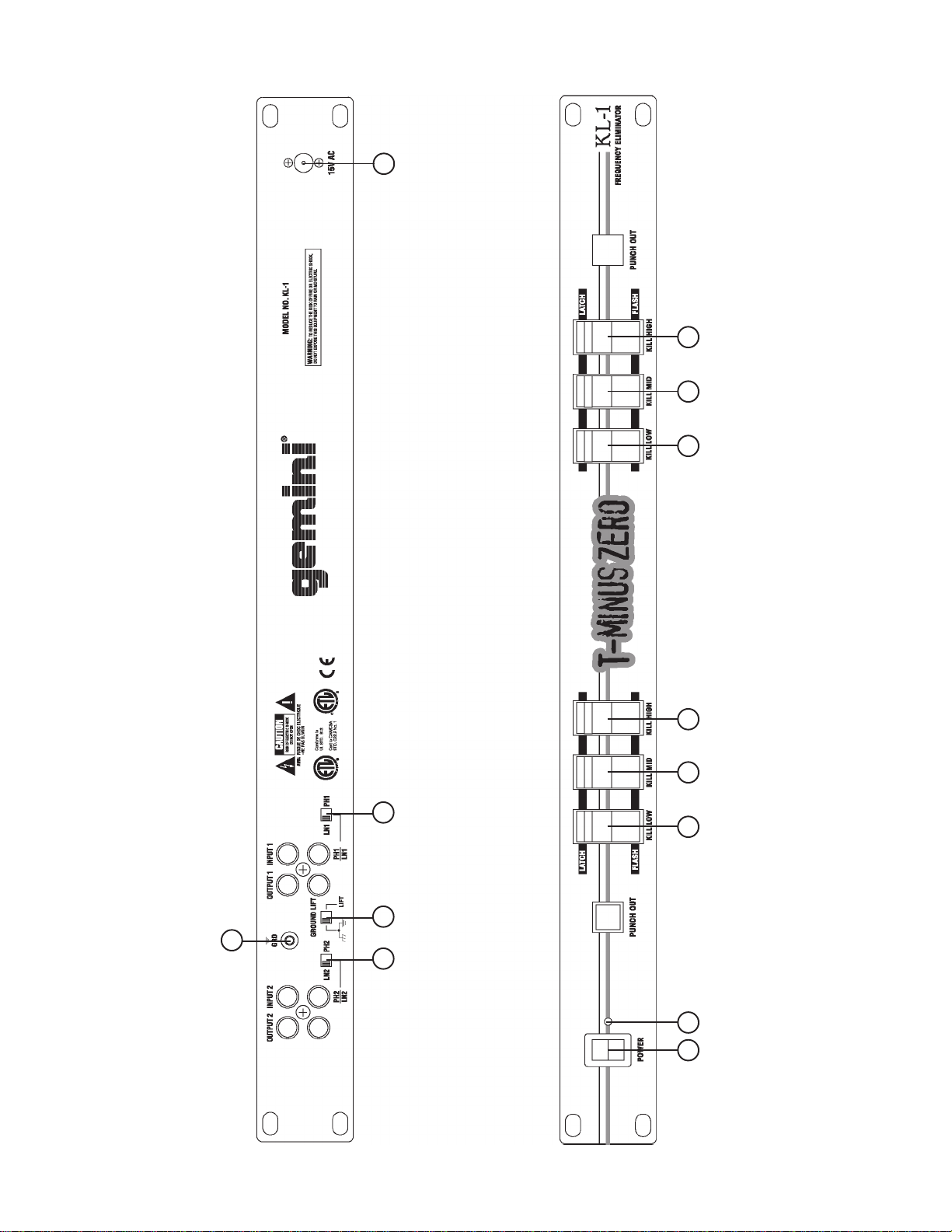
Connections
1. Make sure that the POWER (10) switch is in the OFF position. This
unit comes supplied with a 15 volt AC adaptor. Plug the male pin of
the adaptor into the rear panel POWER JACK (9). Then plug the
adaptor into a proper power source.
2. The KL-1 is supplied with 2 sets of OUTPUT JACKS (1, 6). The
OUTPUT JACKS (1, 6) can be used to connect the KL-1 to the line
inputs of your mixer, amp or any device that accepts line inputs.
3. On the rear panel are 2 stereo PHONO/LINE (2, 7) inputs. The
PHONO/LINE SWITCHES (4, 8) enable you to set the (2, 7) inputs to
Phono or Line. The phono inputs will accept only turntables with a
magnetic cartridge. A GROUND SCREW (3) for you to ground your
turntables is located on the rear panel. The stereo line inputs will
accept any line level input such as a CD player, a cassette player,
etc.
4. If you have more than 2 sources, such as 2 turntables and 2 CD
players, the KL-1 can be inserted between the mixer outputs and the
amplifier. Only one side of the KL-1 is necessary to perform this
function.
Note: you can also use the KL-1 as a stereo device by
connecting the left and right channels to the left and right
mixer outputs. You can use the stereo function to create
interesting panning effects. For example: move the bass
and highs from one side of the room to the other.
Depending on your system configuration, sometimes applying the
ground will create a quieter signal path. Sometimes lifting the ground
can eliminate ground loops and hum to create a quieter signal path.
1. With the unit on, listen to the system in idle mode (no signal present)
with the ground applied (the GROUND LIFT SWITCH (5) in the left
position).
2. Then turn the power off before moving the GROUND LIFT
SWITCH (5). Lift the ground by moving the GROUND LIFT SWITCH
to the right, turn the power back on and listen to determine which
position will provide a signal devoid of background noise and hum.
Keep the GROUND LIFT SWITCH in the ground position if the noise
level remains the same in either position.
CAUTION: Do not terminate the AC ground on the unit in
any way. Termination of the AC ground can be hazardous.
Operation
1. POWER ON: Once you have made all the equipment connections to
your unit, press the POWER (10) switch. The power will turn on and
the POWER LED (11) will glow RED.
2. KILLING FREQUENCIES: There are two ways to kill frequencies,
using the LOW (13, 16), MID (13, 16) and HIGH (22, 23) KILL
SWITCHES. Each Kill Switch has three positions, latch, normal and
flash. When you move the selected KILL SWITCH to the top LATCH
position, the switch will stay there, and the frequency will be killed.
When you move the selected KILL SWITCH to the center position the
kill function is not active, and the frequency will not be killed. When
you move the selected KILL SWITCH to the bottom FLASH position
and hold it there, the frequency will be killed. Releasing the
selected KILL SWITCH from the bottom position will bring it back to
the center position and the frequency will no longer be killed.
SUGGESTION: You can use the Kill Features on each channel to
remove Low, Mid and/or High bands for a smoother mix and to
mix frequencies from both channels to create special effects.
3. PUNCH OUT : The PUNCH OUT BUTT ONS (12, 19) allow you to
remove a channel’s signal from the mix. Press and hold down the
PUNCH OUT BUTTON (12) to remove channel 1’s signal from the
mix. Press and hold down the PUNCH OUT BUTTON (19) to remove
channel 2’s signal from the mix. Releasing the punch out buttons will
bring back the signals to your mix.
SUGGESTION: If you are using a mixer, keep the crossfader in
the center and use the punch outs of both channels together to
create scratch type effects.
Specifications
Input Impedance.........................................................................47Kohm
Output Impedance............................................................300ohm
Max Output Level..............................18V Peak to Peak
Frequency Response....................................20Hz - 20KHz +/- 2dB
Distortion................................................................................<0.01%
Phono S/N Ratio.................................................................better than 90 dB
Line S/N Ratio..................................................................better than 110 dB
Power Source........................................................AC 15V 500mA
Dimensions.........................19” x 1.75” x 2.75” (483 x 44.45 x 70 mm)
Weight..................................................................................3 lbs (1.36 kg)
Page 2

In the USA: If you experience problems with this unit,
call 1-732-738-9003 for Gemini Customer Service.
Do not attempt to return this equipment to your dealer.
Parts of the design of this product may be protected by worldwide patents.
Information in this manual is subject to change without notice and does
not represent a commitment on the part of the vendor. Gemini Sound
Products Corp. shall not be liable for any loss or damage whatsoever
arising from the use of information or any error contained in this manual.
No part of this manual may be reproduced, stored in a retrieval system or
transmitted, in any form or by any means, electronic, electrical, mechanical,
optical, chemical, including photocopying and recording, for any purpose
without the express written permission of Gemini Sound Products Corp.
It is recommended that all maintenance and service on this product is
performed by Gemini Sound Products Corp. or its authorized agents.
Gemini Sound Products Corp. will not accept liability for loss or damage
caused by maintenance or repair performed by unauthorized personnel.
Worldwide Headquarters • 120 Clover Place, Edison, NJ 08837 • USA
T el: (732) 738-9003 • Fax: (732) 738-9006
France • G.S.L. France • 11, A venue Leon Harmel, Z.I. Antony, 92160 Antony, France
Tel: + 33 (0) 1 55 59 04 70 • Fax: + 33 (0) 1 55 59 04 80
Germany • Gemini Sound Products GmbH • Liebigstr. 16, Haus B - 3.0G 85757 Karlsfeld, Germany
Tel: 08131 - 39171-0 • Fax: 08131 - 39171-9
UK • Gemini Sound Products • Unit C4 Hazleton Industrial Estate, Waterlooville, UK P08 9JU
Tel: 087 087 00880 • Fax: 087 087 00990
Spain • Gemini Sound Products S.A. • Rosello, 516, Barcelona, Spain, 08026
Tel: 349-3435-0814 • Fax: 3493-347-6961
© Gemini Sound Products Corp. 2003 All Rights Reserved.
 Loading...