

Page 1
PROFESSIONAL UHF MICROPHONE SYSTEMS
UF-1264 ( M & HL )
OPERATIONS MANUAL
BEDIENUNGSHANDBUCH
MANUAL DE INSTRUCCIONES
MANUEL D’INSTRUCTIONS
FOR ENGLISH READERS Page 2 ~ Page 5
FÜR DEUTSCHE LESER Seite 6 ~ Seite 8
PARA LECTORES EN ESPAÑOL Página 9 ~ Página 11
UTILISATEURS FRANCAIS Page 12 ~ Page 14
UF-2064 ( M & HL )
PROFESSIONELLE UHF MIKROPHONSYSTEME
SISTEMAS DE FRECUENCIA UHF PROFESIONALES DEL MICRÓFONO
SYSTÈMES À FRÉQUENCE UHF PROFESSIONNELS DE MICROPHONE
Page 2
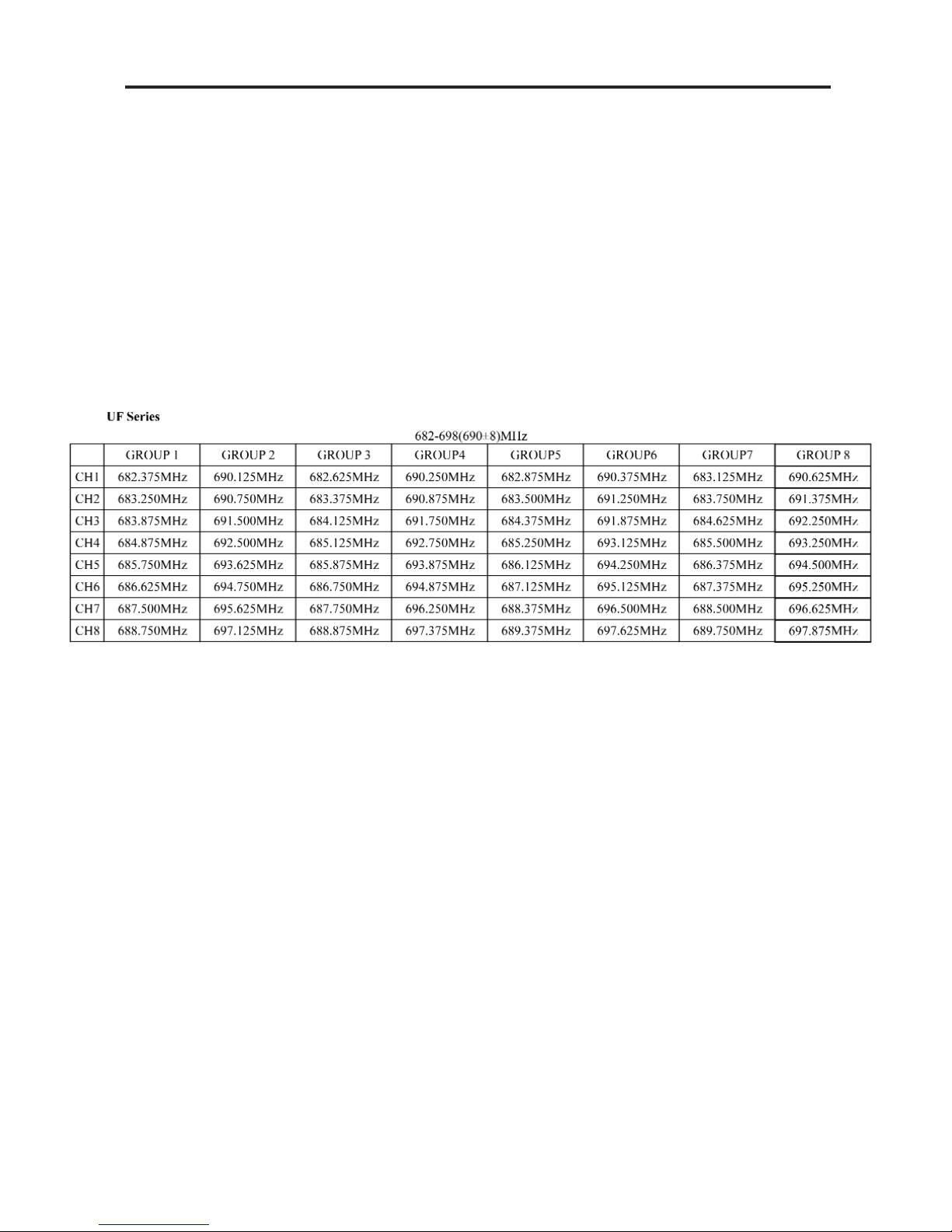
FREQUENCY CHART
AS OF NOVEMEBR 1ST 2008
Page 3
UF SERIES
(2)
Page 4

INTRODUCTION:
Congratulations on your purchase of a GEMINI wireless system. This state of the art
unit includes all the latest features backed by a three year limited warranty. Prior to
use, we suggest that you carefully read the instructions.
FEATURES:
• UF-1264 M includes UF-1264 diversity receiver & FM-64 handheld microphone
• UF-1264 HL includes UF-1264 diversity receiver, FB-64 belt pack transmitter with
mic/line switch & 2 HSL-20 headset mic with mini XLR
• UF-2064 M includes UF-2064 dual receiver, FM-64 handheld microphone
• UF-2064 HL includes UF-2064 dual receiver, 2 FB-64 belt pack transmitters with
mic/line switches, 2 HSL-20 headset mic with mini XLR
• Phase locked loop (PLL) circuitry
• Super high sensitivity with extremely low noise transmission & reception
• Stable & quality SMT assembled PCB module
• Power & RF LEDs
• Squelch control
• FM-64 has a uni-directional dynamic unit microphone
• FM-64/FB-64 has a rechargeable input for battery recharging
CAUTIONS:
1. Some wireless microphone systems require a license. This depends on the fre
quency of the system and the country in which it is to be used. It is the
responsibility of the user to establish if a license is required. As a guide, for the
UK and Europe, VHF radio microphones between 173.800 and 175.000 MHz, or
UHF microphones between 863 MHz and 865 MHz do not need a license. This is
for microphones working at normal power (10mW ERP hand-held or 50mW ERP if
body worn). All other use on alternative frequencies needs a license. More
information on this can be found at : www.jfmg.co.uk/jfmgecom/default.aspx .
If in any doubt, users are advised to investigate the licensing requirements for their
region.
2. All operating instructions should be read before using this equipment.
3. To reduce the risk of electrical shock, do not open the unit. THERE ARE NO
USER REPLACEABLE PARTS INSIDE. Please refer servicing to a qualified
service technician.
4. Do not expose this unit to direct sunlight or to a heat source such as a radiator
or stove.
5. Dust, dirt and debris can interfere with the performance of this unit. Make an
effort to keep the unit away from dusty, dirty environments, and cover the
unit when it is not in use. Dust it regularly with a soft, clean brush.
6. When moving this equipment, it should be placed in its original carton
and packaging. This will reduce the risk of damage during transit.
7. DO NOT EXPOSE THIS UNIT TO RAIN OR MOISTURE.
8. DO NOT USE ANY SPRAY CLEANER OR LUBRICANT ON ANY CONTROLS
OR SWITCHES.
9. REMEMBER, ANY CHANGES MADE TO THE UNIT WITHOUT
AUTHORIZATION FROM GEMINI WILL VOID YOUR WARRANTY.
FCC RULES AND REGULATIONS:
This device complies with part 15 of the FCC rules. Operation is subject
to the following two conditions: (1)This device may not cause harmful
interference and (2) This device must accept any interference received,
including interference that may cause undesired operation.
Notice: The changes or modifications not expressly approved by the
party responsible for compliance could void the user’s authority to
operate the equipment. Important note, to comply with the FCC RF
exposure compliance requirements, no change to the antenna or the device is
permitted. Any change to the antenna or the device could result in the device
exceeding the RF exposure requirements and void user’s authority to operate
the device.
UF WIRELESS SYSTEMS:
The UF wireless systems are high quality audio products that provide
systems available all operate with UHF high band frequencies.
Frequency ranges: USA: 682-698 MHz, Europe 854-865 MHz.
WIRELESS NOTES:
• Before setting up, make sure that the transmitter and receiver are tuned
to the same frequency.
• Do not use two transmitters in the same frequency. Use good quality
batteries to avoid the damage resulting from a defective leaking battery.
• Turn the volume control on the receiver to adjust receiver output level to
match input level requirements of an audio mixer or amplifier.
• While checking sound, move the transmitter around the area where you
use the system to look for dead spots. If you find any dead spot, change
the receiver position. If it does not work, avoid such places.
• To avoid interference, do not put the receiver too near metal object and
avoid obstructions between transmitter and receiver.
• Avoid the interference from TV, radio, other wireless appliances and etc.
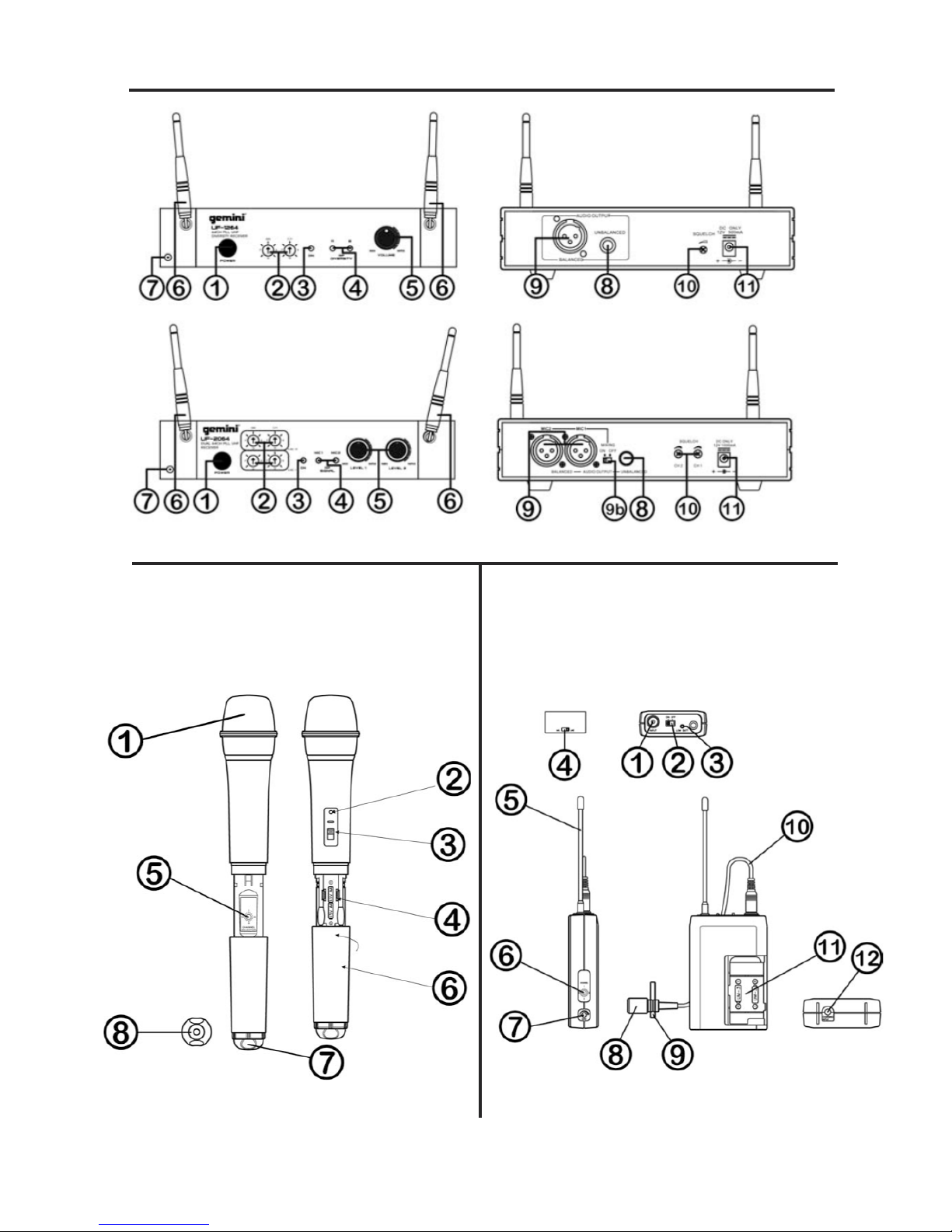
FUNCTION DESCRIPTIONS:
UF RECEIVERS:
These stationary receivers are for use with our 64-channel selectable
transmitters. The receiver operates in UHF band frequency with PLL
synthesized control. Powered by 12V DC.
(1) POWER BUTTON: Push the POWER button to turn the receiver on & off.
(2) CHANNEL SELECTOR: 64 different selectable can be selected used by
rotating the selector(s) or knobs.
(2b) SET: Push the SET button to lock the selected group and channel.
(2c) GR/CH LED: These LED indicates the power is on, and display which
group & channel is on.
(3) POWER INDICATOR: The indicator LED lights when the receiver is ready to
operate.
(4) RF LEVEL INDICATORS: These LED lights to indicate that signal is being
received.
For the UF-1264 the RF LED show the diversity RF signal that is being used A or B.
For the UF-2064 the RF LEd display which MIc is being received MIC 1 or 2
(5) LEVEL CONTROL: Rotary controls adjust the receiver’s output level
from the microphone to line level for matching the input sensitivity of the
mixer or amplifier.
(6) ANTENNA: Fixed-length UHF antenna permanently mounted either on
the front or on rear panel.
(7) DC OUT: Connect the supplied cable to the receiver and the microphone,
and it takes around 10 hours to charge.
(8) UNBALANCED OUTPUT: Unbalanced 1/4” mono jack audio output
provides unbalanced low-impedance output
(9) BALANCED OUTPUT: 3-pin XLR connector provides balanced low impedance
output
(10) SQUELCH ADJ: The squelch adjusts the output level to prevent from
the external noise. Setting the squelch too high will reduce the range of
the system. Set the squelch to minimum before turning the receiver on.
(11) DC IN: Input connector for the supplied AC adapter.
FM-64 HANDHELD MICROPHONE:
The handheld microphone operates in UHF band frequency with PLL
synthesized control. UHF 64 preprogramed selectable frequencies to
avoid interference. Uni-directional dynamic or uni-directional electret
condenser capsules with different characters for various choices. Use
1.5V x 2 AA size rechargeable or regular batteries for low operating cost.
(1) GRILLE: Protects the microphone capsule and helps reduce breath
sounds and wind noise. The grille for the various microphone capsules
differ in appearance.
(2) LOW BATTERY LED: LED indicates battery status. Switching the power
to “ON”, the LED flashing once indicates that the transmitter has
sufficient power. If the LED stays on, it indicates that the battery has
insufficient power and should be changed soon. If the status LED fails to
flash, the battery is either dead or not positioned correctly, and you
should correct the positioning or change the battery.
(3) ON/OFF SWITCH: Turns transmitter power on and off.
(4) BATTERY COMPARTMENT: Insert two AA batteries into the excellent
performance under most operating conditions. The different
compartment and make sure that the polarity of batteries is correct.
(3)
Page 5
(5) CHANNEL SELECTOR: Changes transmitter channel setting.
(6) BATTERY COVER: Push to expose battery compartment and channel selector.
(7) COLOR CLIP: This color clip helps to identify the frequency for multichannel
operation.
(8) CHARGING INPUT: The inserted rechargeable batteries can be charged
by using the supplied DC-plug cable connection to DC Out on the
receiver. It takes up to 10 hours for charging.
FB-64 BODYPACK TRANSMITTER:
The bodypack transmitter operates in UHF band frequency with PLL
synthesized control. UHF 64 preprogrammed selectable frequencies to
avoid interference. Various uni-directional electret condenser capsule
options. Use 1.5V x 2 AA size batteries for low operating cost.
(1) INPUT CONNECTOR: Mini XLR microphone connector, connect the
headset or lavalier here.
(2)ON/OFF SWITCH: Turns transmitter power on and off.
(3)LOW BATTERY LED: LED indicates battery status. Switching the power
to “ON”, the LED flashing once indicates that the transmitter has
sufficient power. If the LED stays on, it indicates that the battery has
insufficient power and should be changed soon. If the status LED fails to
flash, the battery is either dead or not positioned correctly, and you
should correct the positioning or change the battery.
(4) MIC/LINE SELECTOR (optional for use with mini XLR connector):
This switch sets the audio input either to microphone level or line level.
(5) ANTENNA: Permanently connected, helical antenna.
(6) CHANNEL SELECTOR: Changes transmitter channel setting.
(7) GAIN: The rotary control adjusts the sensitivity of the transmitter’s audio
to the level of the connected lapel microphone or instrument.
(8)MIC. UNIT: The uni-directional electret condenser unit features the wide
frequency response for warm, rich bass and clear sound.
(9)TIE CLIP: Use to clip onto shirt or tie. for free movement.
(10) CABLE: Connect the CABLE to the mini XLR connector to connect to the
transmitter
(11) BATTERY COMPARTMENT: Insert two AA batteries into the
compartment and make sure that the polarity of batteries is correct.
(12) CHARGING INPUT: The inserted rechargeable batteries can be
charged by using the supplied DC-plug cable connection to DC Out on
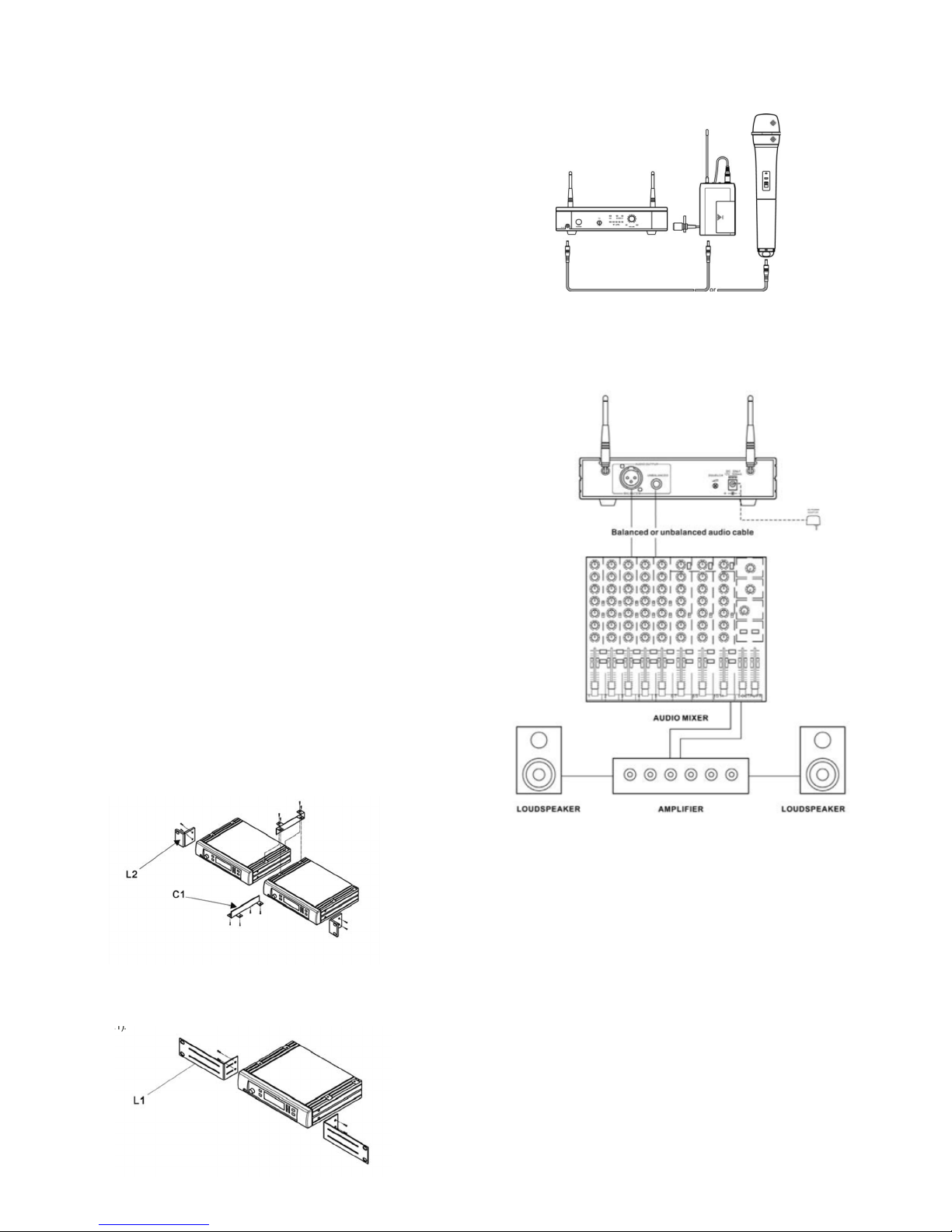
the receiver. It takes up to 10 hours for charging. To combine two receivers in a
19" standard rack by using 2 short L type plastic racks (L2) and 2 metal connecting
plates (C1). (Each system includes a L2 and a C1.)
To mount a receiver in a 19" standard rack by using 2 long L type metal
racks (L1).
CHARGING CONNECTING DIAGRAM:
Connect the supplied DC cable to the receiver and the microphone, and it takes
around 10 hours to charge and the LED of transmitter is flashing all the time.
BASIC CONNECTIONS:
Connect the receiver output to the audio mixer or amplifier input, using a
standard audio cable with XLR connectors or 1/4” phone plugs. Never
use the balance & unbalanced outputs at the same time! This may
cause signal loss or increased noise.
SETTING UP:
Prior to setting up, check that the transmitter and receiver are tuned to
the same frequency. Two or above transmitters operating in the same
frequency can not be used at the same time and area, so please select
the different frequencies which can be used simultaneously at local area.
CONNECTING THE RECEIVER TO POWER:
• Point the antennas upward.
• Check that the voltage of the supplied AC adapter (AC110 or AC220)
conforms to the voltage available in local area. Using the wrong AC
adapter may cause irreparable damage to the unit.
• Plug the feeder cable of the supplied AC adapter into DC IN socket on
the receiver. Then plug the AC adapter into a power outlet.
CONNECTING THE RECEIVER TO AN AUDIO MIXER
OR AN AMPLIFIER:
In order to make sure the sound quality and avoid distortion, please
adjust the volume level according to following instructions.
(4)
Page 6

INSERTING BATTERIES INTO THE HANDHELD /
BODYPACK TRANSMITTER:
• Push to open the battery cover and insert batteries into the battery
compartment conforming to the polarity (+)(-) marks. The transmitter can
not work with incorrectly inserted batteries.
• When push the ON/OFF switch to “ON” to switch the power on, the LED
will flash momentarily. If the battery has sufficient power, the LED flashes
once. If the LED stayed on, it indicates that the battery has insufficient
power and should be changed soon. If the status LED fails to flash, the
battery is either dead or not positioned correctly, and you should correct the
positioning or change the battery.
• Push back the battery cover to click it shut.
SETTING UP THE HANDHELD TRANSMITTER:
• Switch the receiver power on and check the frequency and volume level.
• Switch the transmitter and hi-fi appliance (amplifier, tape deck etc.) power on.
• Test the microphone and adjust the levels on your mixer or amplifier.
• When using a standard audio cable with 1/4” phone plugs to plug into
the MIC IN on the audio mixer or on the amplifier, please turn the Volume
Level Control on the receiver to around 1 o’clock position, the output
level for balanced and unbalanced output is about at 77mV.
• When using a standard audio cable with 1/4” phone plugs to plug into
the LINE IN on the mixer, please turn the Volume Level Control on the
receiver to around MAX position, the output level for unbalanced and
balanced output is about at 770mV.
SETTING UP THE BODYPACK TRANSMITTER:
CONNECTING A MICROPHONE:
• Open the battery cover. Push the MIC/LINE switch to “MIC” and use the
supplied screwdriver to adjust the GAIN at appropriate position.
• Plug the mini XLR connector end of the microphone cable into the audio
input connector on the bodypack transmitter.
• Switch the transmitter and hi-fi appliance (amplifier, tape deck etc.) power on.
• Test the microphone and adjust the levels on your mixer or amplifier.
CONNECTING AN INSTRUMENT
• Open the battery cover. Push the MIC/LINE switch to “LINE” and use the
supplied screwdriver to adjust the GAIN at appropriate position.
• Plug the 1/4” phone plug of the optional guitar cable to the output jack
on the instrument and the mini XLR plug into audio input connector on the
bodypack transmitter.
• Switch the transmitter and hi-fi appliance (amplifier, tape deck etc.)
power on.
• Play the instrument for testing and adjust the levels on your mixer or
amplifier.
TROUBLESHOOTING:
NO SOUND:
Check the power supply of the microphone and receiver.
Check that the transmitter and receiver are tuned to the same frequency.
Check whether the hi-fi appliance is switched on and the receiver output
is connected to mixer or amplifier input.
Check whether transmitter is too far away from receiver or SQUELCH
control set too high.
Check whether receiver is located too near metal object or there are
obstructions between transmitter and receiver.
SOUND INTERFERENCE:
Check the antenna location.
When using 2 or above microphone sets simultaneously, make sure
that the chosen frequencies are not interfered.
Check whether the interference comes from other wireless microphones,
TV, radio and etc.
DISTORTION:
Check the volume level of the receiver is set too high or too low.
Check whether the interference comes from other wireless
SPECIFICATIONS:microphones, TV, radio and etc.
SPECIFICATIONS:
UF-1264:
Frequency range:.........................................USA: 682-698MHz, Europe: 854-865MHz
Case..................................................................................................Half 19” EIA Case
Receiving System................................................................................PLL synthesized
Receiving Mode..........................................64CH, Single Channel, Switching diversity
Frequency Stability.........................................................................................+/- 0.05%
Receiving Sensitivity......................................................At 8 dBuV over 80dB S/N ratio
Image & Spurious Rej. .........................................................................80 dB minimum
Selectivity............................................................................................................> 50dB
Modulation Mode......................................................................................................FM
IF Frequency1st:.................................................................1st: 56MHz, 2nd: 10.7MHz
Dynamic Range...................................................................................................>96dB
Tone Signal...................................................................................................32.768KHz
S/N Response.....................................................Over 94dB, at 48KHz deviation and
60dBuV antenna input
AF Response...........................................................................50Hz to 15KHz(+/-3dB)
T.H.D. .....................................................................................................1%(at 1KHz)
Power Supply............................................................................................DC 12 ~ 18V
Audio Output.................................................................Balanced & unbalanced output
Current Consumption..........................................................................260mA +/- 10mA
Dimension(mm)WxHxD.........................................................................210 x 44 x 165
UF-2064
Frequency range:........................................USA: 682-698MHz, Europe: 854-865MHz
Case..................................................................................................Half 19” EIA Case
Receiving System................................................................................PLL synthesized
Receiving Mode.....................................................64CH, Dual Channel, Non-diversity
Frequency Stability.........................................................................................+/- 0.05%
Receiving Sensitivity......................................................At 8 dBuV over 80dB S/N ratio
Image & Spurious Rej. ........................................................................80 dB minimum
Selectivity............................................................................................................> 50dB
Modulation Mode......................................................................................................FM
IF Frequency1st:..................................................................1st: 56MHz, 2nd: 10.7MHz
Dynamic Range..................................................................................................>96dB
Tone Signal...................................................................................................32.768KHz
S/N Response...................Over 94dB, at 48KHz deviation and 60dBuV antenna input
AF Response............................................................................50Hz to 15KHz(+/-3dB)
T.H.D. ........................................................................................................1%(at 1KHz)
Power Supply.............................................................................................DC 12 ~ 18V
Audio Output.................................................................Balanced & unbalanced output
Current Consumption.........................................................................260mA +/- 10mA
Dimension(mm)WxHxD..........................................................................210 x 44 x 165
FM-64
Mic Type..........................................................................64CH, Handheld microphone
Frequency range:.........................................USA: 682-698MHz, Europe: 854-865MHz
RF Power Output.......................................................................................10mW(max.)
Oscillation Mode..................................................................................PLL synthesized
Frequency Stability.......................................................................................+/- 0.005%
Maximum Deviation...............................................+/-48KHz with limiting compressor
Spurious Emission......................................................>60 dB below carrier frequency
T.H.D. ..............................................................................................1%(at 1KHz)
Chargeable Battery..................................................DC 3V(1.5v x 2 AA size batteries)
Tone Key...................................................................................................32.768KHz
Mic Unit..............................................................................Uni-directional dynamic unit
LED Indicator...............................................................Power ON-OFF and low battery
Current Consumption...................................................................................65 +/- 5mA
Dimension(mm)WxHxD....................................................................................267 x 55
FB-64:
Mic Type...........................................................................64CH, Bodypack transmitter
Frequency range:........................................USA: 682-698MHz, Europe: 854-865MHz
RF Power Output......................................................................................10mW (max.)
Oscillation Mode..................................................................................PLL synthesized
Frequency Stability.......................................................................................+/- 0.005%
Maximum Deviation.................................................+/-48KHz with limiting compressor
Spurious Emission......................................................>60 dB below carrier frequency
T.H.D. ........................................................................................................1%(at 1KHz)
Chargeable Battery.................................................DC 3V (1.5v x 2 AA size batteries)
Tone Key.......................................................................................................32.768KHz
Mic Unit...........................................................................Uni-directional condenser unit
LED Indicator...............................................................Power ON-OFF and low battery
Current Consumption...................................................................................65 +/- 5mA
Dimension(mm)WxHxD..............................................................................66 x 97 x 25
DESIGN AND SPECIFICATIONS SUBJECT TO CHANGE WITHOUT NOTICE.
(5)
Page 7

EINFÜHRUNG:
Herzlichen Gluckwunsch zum Erwerb einer drahtlosen GEMINI UHFAnlage.
Sie ist nach dem neuesten stand der Technik hergestellt und mit
einer Garantie von drei Jahren versehen. Bitte lesen Sie vor dem
Gebrauch der Anlage alle Anweisungen sorgfältig durch.
FEATURES:
• UF-1264 M besteht aus dem UF-1264 Diversity-Empfänger und dem
Handsender FM-64
• UF-1264 H beinhaltet den Diversity-Empfänger UF-1264, den Taschensender
FB- 64 mit Mic-/Lineschalter und das Headset HSL-20 mit Mini-XLR-Stecker.
• UF-2064 M besteht aus dem UF-2064 Doppelempfänger und 2 Handsender FM-64
• UF-2064 HL beinhaltet den Doppel-Empfänger UF-2064, den Handsender FM-64,
den Taschensender FB-64 mit Mic-/Lineschalter und das Headset HSL-20 mit
Mini-XLR-Stecker
• PLL-Schaltkreis Hohe Übertragungsempfindlichkeit bei niedrigstem Rauschen
• Stabile und hochqualitative SMT-Platinen
• LED´s fur RF-Signal und Einschaltkontrolle im Empfänger
• UF-1264 LED´s fur 2 x RF-Signal und 1 Einschaltkontrolle im Empfänger
• Regelbare Rauschsperre (Squelch)
• FM-64 hat ein dynamisches Mikrofon mit Nierencharakteristik und
nachladbarem Eingang
• FB-64 Taschensender mit Mini-XLR-Buchse und nachladbarem Eingang
WICHTIGE HINWEISE:
1. Vor der Inbetriebnahme der Funkanlage ausserhalb des
Frequenzbereiches 863 - 865 MHz, wenden Sie Sich bitte unbedingt an
die zuständige locale Regulierungsbehörde oder besuchen Sie: http://
www.regtp.de/schriften/02222/01/index.html um die anmelde- und
gebuhrenpflichtigen Frequenzen einzusehen.
2. Vor Gebrauch der UHF-Anlage bitte alle Anweisungen lesen.
3. Um einen Stromschlag zu vermeiden, das Gerät nicht öffnen. Es
beinhaltet keine vom Anwender auszutauschenden Teile. Bitte setzen Sie
sich im Servicefall mit Ihrem Händler in Verbindung.
4. Setzen Sie die Anlage keiner großen Wärme (Heizung, Ofen) und keiner
direkten Sonnen- einstrahlung aus.
5. Schmutz und Staub können den Betrieb der Anlage stören. Vermeiden
Sie daher den Betrieb in staubiger Umgebung und decken Sie die Anlage
bei nicht Betrieb ab. Reinigen nur mit einem trocken weichen Tuch.
6. Zum Transport und Schutz gegen Schäden eignet sich am Besten die
Originalverpackung-
7. SETZEN SIE DIE ANLAGE KEINER STARKEN FEUCHTIGKEIT ODER REGEN
AUS.
8. NEHMEN SIE NIEMALS KONTAKTSPRAYS ODER SPRÜHÖL FÜR
DIE SCHALTER UND REGLER
9. BITTE DENKEN SIE DARAN DAS BEI JEDEM TECHNISCHEN
EINGRIFF INNERHALB DER GARANTIEZEIT DER
GARANTIEANSPRUCH ERLISCHT.
FCC UND RBT BESTIMMUNGEN:
Diese Anlage entspricht den Bestimmungen der RBT fur drahtlose UHFAnlagen
und den FCC Bestimmungen nach Teil 15. Der Betrieb muß die
folgenden beiden Bedingungen erfullen: (1)Diese Anlage darf im Betrieb
keine Störungen (Interferenzen) verursachen und (2) muß beim Empfang
Störungen (Interferenzen) akzeptieren auch solche, die einen normalen
Betrieb ausschließen.
Achtung: Änderungen und Modifikationen die vom Hersteller nicht
erprobt und zugelassen sind, fuhren zum Erlöschen der
Betriebserlaubnis der Anlage.
Wichtig: Um den Bestimmungen zur Abstrahlung von UHF-Frequenzen
zu entsprechen, durfen an den Geräten oder den Antennen keine
Änderungen vorgenommen werden. Jede Änderung kann die UHFStrahlung
verstärken und fuhrt zum Erlöschen der Betriebserlaubnis.
UF drahtlos UHF-Systeme:
Die UF-Serie besteht aus qualitativ hochwertigen Audiosysteme, die
unter fast allen Bedingungen hervorragend funktionieren. Die
verschiedenen Systeme arbeiten alle im UHF-Bereich. Frequenzbereiche:
USA: 682-698 MHz, Europe 854-865 MHz.
HINWEISE ZUM DRAHTLOSBETRIEB:
• Vor dem Betrieb an einer Audioanlage, Sender und Empfänger auf die
gleiche Frequenz ein-stellen.
• Betreiben Sie nie zwei Sender mit gleicher Frequenz. Nehmen Sie zum
Betrieb nur qualitativ hochwertige Batterien um Schäden durch
Batterielecks zu vermeiden. Passen Sie den Ausgangspegel des
Empfängers mit dem Lautstärkeregler, an die Eingangs-empfindlichkeit
Ihres Mixers oder Verstärkers an.
• Beim Soundcheck gehen Sie mit dem Sender den gesamten
Anwendungsbereich des Systems ab um eventuelle Empfangslöcher
aufzuspuren. Wenn Sie solche Löcher finden sollten, verändern sie die
Position des Empfängers und testen sie erneut.
• Um Störungen(Interferenzen) zu vermeiden, stellen Sie den Empfänger
nicht zu nahe an Metallgegenstände und arbeiten Sie mit dem Sender
nicht zu dicht am Empfänger.
• Vermeiden Sie Störungen durch Radios, Fernseher oder andere Drahtlosanlagen
FUNKTIONSBESCHREIBUNG:
UF-EMPFÄNGER:
Diese stationären Empfänger sind fur den Betrieb mit unseren Sendern
mit 64 wählbaren Kanälen vorgesehen. Sie arbeiten im UHF-Band mit
Synthesizergesteuertem PLL-Schaltkreis. Die Betriebsspannung beträgt
12V Gleichspannung.
(1) POWER KNOPF: Zum Ein- / und Ausschalten diesen Knopf drucken.
(2) CHANNEL SELECTOR: Mit diesem Kanalwähler können durch Drehen
des Knopfes 64 Kanäle eingestellt werden.
(2B) SET: Zum Speichern des Kanals oder der Gruppe diesen Knopf drucken.
(2C) GR/CH LED: LED-Display zeigt Gruppe / Kanal und Ein / Aus an
(3) POWER INDICATOR: LED leuchtet nach dem Einschalten auf.
(4) RF LEVEL INDICATORS: Diese LED´s zeigen ein empfangenes Signalan.
Beim UF-1264 wird das Diversitysignal an A oder B angezeigt.
Beim UF-2064 wird das RF-Signal von Mic1 oder Mic2 angezeigt.
(5) LEVEL CONTROL: Mit den Pegelreglern wird der Ausgangspegel zur
Anpassung an den Mixer oder Verstärker eingestellt.
(6) ANTENNA: Fest montierte UHF-Antenne an der Vorder- oder Ruckseite.
(7) DC OUT: Schließen Sie hier das beigefugte Kabel an um die
Senderakkus zu laden. Die Ladedauer beträgt ca. 10 Std.
(8) UNBALANCED OUTPUT: unsymmetrische Klinkenbuchse mit niedriger
Impedanz.
(9) BALANCED OUTPUT: symmetrischer XLR-Steckerausgang mit
niedriger Impedanz.
(10) SQUELCH ADJ: Mit dem Squelchregler wird die Empfängerempfindlichkeit
verändert. Je höher der Squelch ist, um so niedriger ist die
Eingangsempfindlichkeit und die Reichweite. Setzen Sie den Squelch vor
dem Einschalten auf Minimum.
(11) DC IN: Anschluß fur das Steckernetzteil.
FM-64 HANDSENDER:
Der Handsender arbeitet im UHF Band mit Synthesizergesteuertem PLLKreis.
Zur Vermeidung von Störungen ist der Sender mit 64 wählbaren,
vorprogrammierten Kanälen ausgestattet. Als Mikrofonkapsel ist ein
dynamisches System und ein Electretkondensatorsystem, jeweils mit
Nierencharakteristik verfugbar. Aus Umweltschutzgrunden und zur
Kostenersparnis verwenden Sie wiederaufladbare 2x 1,5V-MignonNickel-Cadmium-Akkus.
(1) GRILLE: Schutzt die Mikrofonkapsel und verringert Atem- und
Windgeräusche. Je nach verwendeter Kapsel ist der Schutzkorb
unterschiedlich geformt.
(2) LOW BATTERY LED: Die LED zeigt den Batteriestaus an. Wenn die
LED nach dem Einschalten einmal kurz aufleuchtet, sind die Batterien in
Ordnung. Bleibt die LED leuchten, mussen die Batterien bald gewechselt
werden. Leuchtet die LED nicht sind die Batterien leer oder falsch gepolt
eingelegt.
(3) ON/OFF SWITCH: Schaltet den Sender Ein und Aus.
(4) BATTERY COMPARTMENT: Achten Sie beim Einlegen der Akkus oder
Batterien (2x Mignon) auf die richtige Polung.
(6)
Page 8

(5) CHANNEL SELECTOR: Drehen Sie diesen Knopf um den Kanal zu ändern.
(6) BATTERY COVER: Abschrauben um das Batteriefach zu öffnen und
den Kanalknopf zu bedienen.
(7) COLOR CLIP: Diese Farbkappe erleichtert die Markierung der Sender in
Mehrkanalanlagen.
(8) CHARGING INPUT: Hier das beigefugte Ladekabel anschließen und mit
dem Empfänger verbinden um die Akkus aufzuladen (ca. 10 Std.).
Ladekabel nicht bei Trockenbatterien verwenden.
FB-64 TASCHENSENDER:
Der Taschensender arbeitet im UHF Band mit Synthesizergesteuertem
PLL-Kreis. Zur Vermeidung von Störungen ist der Sender mit 64
wählbaren, vorprogrammierten Kanälen ausgestattet. Es können
verschiedene Electretkondensatormikrofone an die Mini-XLR-Buchse
angeschlossen werden. Verwenden Sie 2x 1,5V Mignon Batterien oder
wieder-aufladbare Mignon-Akkus
(1) MINI-XLR-BUCHSE: Schliessen Sie hier das beiliegende
Electretkondensatormikrofon an
(2) ON/OFF SWITCH: Schaltet den Sender Ein und Aus.
(3) LOW BATTERY LED: Die LED zeigt den Batteriestaus an. Wenn die
LED nach dem Einschalten einmal kurz aufleuchtet, sind die Batterien in
Ordnung. Bleibt die LED leuchten, mussen die Batterien bald gewechselt
werden. Leuchtet die LED nicht sind die Batterien leer oder falsch gepolt eingelegt.
(4) MIC/LINE SELECTOR: Umschalter fur Mikrofon- oder Linepegeleingang.
(5) ANTENNA: Fest montierte Antenne.
(6) CHANNEL SELECTOR: Ädert den Sendekanal.
(7) GAIN: Ändert die Eingangsempfindlichkeit fur Mikrofon oder Instrument.
(8) MC.UNIT: Das Electretkondensatormikrofon mit Nierencharakteristik
sorgt mit seinem großen Frequenzumfang fur warmen klaren Klang und
gute Basswiedergabe.
(9) TIE CLIP: Zum Anklemmen des Lavaliermikrofons an die Krawatte oder
die Knopfleiste.
(10) CABLE: Kabel mit Mini-XLR-Stecker zum Anschluß an den
Taschensender.
(11) BATTERY COMPARTMENT: Legen Sie 2x Mignonbatterien oder
Akkus mit richtiger Polung in das Batteriefach.
(12) CHARGING INPUT: Hier das beigefugte Ladekabel anschließen und
mit dem Empfänger verbinden um die Akkus aufzuladen (ca. 10 Std.).
Ladekabel nicht bei Trockenbatterien verwenden.
Um zwei Empfänger zu kombinieren und in ein 19"-Rack einzubauen, sind
jedem System ein Plastikwinkel (L2) und ein Metallverbinder (C1) beigelegt
Um einen Receiver in ein 19"-Rack einzubauen, benötigen Sie
zwei lange Metallwinkel (L1).
CHARGING CONNECTING DIAGRAM:
Verbinden Sie den Sender mit Hilfe des beigefugten DC-Kabels mit dem
Empfänger und laden Sie den Sender in ca. 10 Std. auf.
EINSTELLUNGEN UND BETRIEB:
Stellen Sie zuerst sicher, das Sender und Empfänger auf die gleiche
Frequenz eingestellt sind. Es können keine zwei Sender gleichzeitig mit
der gleichen Frequenz betrieben werden.
ANSCHLIESSEN DER GERÄTE:
Verbinden Sie den Audioausgang mit dem Eingang eines Mixers oder
Verstärkers mit Hilfe eines Standard-XLR- oder Klinkenkabels. Benutzen
Sie niemals beide Ausgänge gleichzeitig.
ANSCHLUß DES EMPFÄNGERS AN DAS NETZ:
Die fest montierten Antennen senkrecht stellen. Überprufen Sie ob das
Steckernetzteil fur die vorhandene Netzspannung ausgelegt ist (110V
oder 220V). Ein falsches Steckernetzteil kann zur Zerstörung des
Empfängers fuhren. Stecken Sie den DC-Stecker des Anschlußkabels in
die DC-In-Buchse und das Steckernetzteil in eine Netzsteckdose.
ANSCHLUß AN EINEN MIXER ODER VERSTÄRKER:
Um Verzerrungen zu vermeiden und eine gute Soundqualität zuerreichen
beachten Sie bitte nachfolgende Anweisungen.
EINSETZEN DER BATTERIEN IN HAND- UND TASCHENSENDER:
Öffen Sie das Batteriefach und legen Sie die Batterien oder Akkus richtig
gepolt ein. (markiert mit + / -) Bei falscher Polung funktionieren die
Sender nicht. Schalten Sie den Sender ein. Wenn die LED nach dem
Einschalten einmal kurz aufleuchtet, sind die Batterien in Ordnung. Bleibt
die LED leuchten, mussen die Batterien bald gewechselt werden.
Leuchtet die LED nicht sind die Batterien leer oder falsch gepolt
eingelegt. Schließen Sie das Batteriefach wieder bis es hörbar einrastet.
(7)
Page 9

INBETRIEBNAHME DES HANDSENDERS:
Schalten Sie den Empfänger ein und prufen Sie die Frequenz und den
Lautstärkepegel. Schalten Sie den Sender und den Mixer / Verstärker
ein. Testen Sie das Mikrofon und stellen Sie die gewunschte Lautstärke
ein. Wenn der Empfänger an den Mikrofoneingang des Mixers /
Verstärkers angeschlossen ist, drehen Sie den Pegelregler auf ca 1UhrPosition(ca77mV). Ist der Empfänger an einen Lineeingang
angeschlossen drehen Sie den Pegelregler auf maximum(ca770mV).
INBETRIEBNAHME DES TASCHENSENDERS:
A. ANSCHLUß EINES MIKROFONS:
Öffnen Sie das Batterifach und stellen Sie den Mic/Line-Schalter auf
Mic.. Justieren Sie mit dem beigelegten Schraubendreher den
Gainregler. Stecken sie den Mini-XLR-Stecker des Mikrofons in die
Eingangsbuchse des Taschensenders. Schalten Sie den Taschensender
und den Mixer / Verstärker ein. Testen Sie das Mikrofon und stellen Sie
die gewunschte Lautstärke ein.
B. ANSCHLUß EINES INSTRUMENTS:
Öffnen Sie das Batterifach und stellen Sie den Mic/Line-Schalter auf
Line. Justieren Sie mit dem beigelegten Schraubendreher den
Gainregler. Stecken sie den Mini-XLR-Stecker des Instrumentkabels in
die Eingangsbuchse des Taschensenders und das andere Ende ins
Instrument. Schalten Sie den Taschensender, das Instrument und den
Mixer / Verstärker ein. Spielen Sie das Instrument und stellen Sie die
gewunschte Lautstärke ein.
STÖRUNGSBESEITIGUNG:
KEIN TON HÖRBAR:
Überprufen Sie die Stromversorgung des Empfängers und die Batterien /
Akkus des Senders.
Überprufen Sie ob Sender und Empfänger auf die gleiche Frequenz
eingestellt sind.
Überprufen Sie Ihre Audioanlage und die Verbindungsleitungen.
Überprufen Sie die Reichweite bzw. die Squelcheinstellung.
Überprufen Sie ob ein freier Empfang möglich ist oder sich störende
Gegenstände zwischen Sender und Empfänger befinden.
TONSTÖRUNGEN(INTERFERENZEN):
Überprufen sie die Antennenposition.
Wenn Sie ein Multikanalsystem verwenden, stellen Sie sicher, das sich
die Frequenzen nicht gegenseitig beeinflussen.
Überprufen Sie ob sich andere Störquellen (Radios Fernseher, andere
Funksysteme o.ä.) in der Nähe befinden.
VERZERRUNGEN:
Überprufen Sie die Ausganspegel des Audiosignals am empfänger und
die Eingangsregler des Mixers / Verstärkers.
Überprufen Sie ob sich andere Störquellen (Radios Fernseher, andere
Funksysteme o.ä.) in der Nähe befinden.
TECHNISCHE DATEN:
UF-1264:
Frequenzbereich:........................................USA 682-698 MHz, Europe: 854-865 MHz
Gehäuse:.................................................................................................9,5"-Gehäuse
Empfangssystem:............................................................................….PLL-Synthesizer
Empfangsmodus:...................................64 Kanäle, einkanaliges Diversity(geschaltet)
Frequenzstabilität:……………….......................…....……………………………....0.05%
Empfangsempfindlichkeit:...................................................bei 8dBuV >80dB S/N-ratio
Ruckwärtsdämpfung:.............................................................................80dB minimum
Kanaltrennung:....................................................................................................>50dB
Modulation: ..............................................................................................................FM
IF Frequenz:…………………………….....................…….....…1: 56MHz. ; 2: 10.7MHz.
Dynamikbereich:…………………………........……...................................………>96dB
Tonfrequenz:………………………….....................…………………………..32.768KHz
Geräuschabstand:…..........>94dB bei 48KHz Bandbreite und 60dB Antenneneingang
Audiofrequenzbereich:......................................................50Hz. bis 15 KHz. (+ / -3dB)
T.H.D. :...................................................................................................<1% bei 1KHz.
Spannungsversorgung:.........................................................Gleichspannung 12V-18V
Audioausgang:.....................................symmetrische und unsymmetrische Ausgänge
Stromaufnahme:..................................................................................300mA +/- 10mA
Abmessungen(in mm):...............................................................(B) 210.(H) 44.(T) 165
UF-2064:
Frequenzbereich:........................................USA 682-698 MHz, Europe: 854-865 MHz
Gehäuse:................................................................................................9.5"- Gehäuse
Empfangssystem:...........................................................................….PLL-Synthesizer
Empfangsmodus: ...............................................64 Kanäle, zweikanalig, kein diversity
Frequenzstabilität:…………………..................…………………………………....0,05%
Empfangsempfindlichkeit:...................................................bei 8dBuV >80dB S/N-ratio
Ruckwärtsdämpfung:............................................................................80dB minimum
Kanaltrennung:....................................................................................................>50dB
Modulation:...............................................................................................................FM
IF Frequenz:……………….......................................……..……1: 56MHz. ;2: 10.7MHz.
Dynamikbereich:………………………………......................………………………>96dB
Tonfrequenz:…………………………………..........…………………………..32.768KHz
Geräuschabstan...........…..>94dB bei 48KHz Bandbreite und 60dB Antenneneingang
Audiofrequenzbereich:......................................................50Hz. bis 15 KHz. (+ / -3dB)
T.H.D. :...................................................................................................<1% bei 1KHz.
Spannungsversorgung:........................................................Gleichspannung 12V -18V
Audioausgang:......................................symmetrische und unsymmetrische Ausgänge
Stromaufnahme:..................................................................................260mA +/- 10mA
Abmessungen(in mm): ...............................................................(B) 210.(H) 44.(T) 165
FM-64:
Typ:.............................................................................................64 Kanal-Handsender
Frequenzbereich:.........................................USA 682-698MHz, Europe: 854-865 MHz
Sendeleistung:............................................................................................10mW(max)
Oszillator:.......................................................................................….PLL-Synthesizer
Frequenzstabilität:…………….................…………………..…………………+/- 0,005%
Maximale Bandbreite:………..............……..........................48KHz.mit Comp.-/ Limiter
Maximale Störstrahlung:....................................................60dB unter Trägerfrequenz
T.H.D.:......................................................................................................1% bei 1KHz.
Spannungsversorgung:........................................2x 1,5V Mignonbatterien oder Akkus
Tonfrequenz:..............................................................................................32,768KHz.
Mikrofonkapsel: ......................................dynamische Kapsel mit Nierencharakteristik
LED:................................................................................Ein/Aus und Batteriezustand
Stromverbrauch:........................................................................................65mA / 5mA
Abmessungen in mm:.........................................................(L) 267 x (Durchmesser) 5
FB-64:
Frequenzbereich:........................................USA 682-698MHz, Europe: 854-865 MHz
Typ:........................................................................................................Taschensender
Sendeleistung:............................................................................................10mW(max)
Oszillator:........................................................................................….PLL-Synthesizer
Frequenzstabilität:……………………..............................………………………..0,005%
Maximale Bandbreite:……………........................................48KHz.mit Comp.-/ Limiter
Maximale Störstrahlung:.....................................................60dB unter Trägerfrequenz
T.H.D.:......................................................................................................1% bei 1KHz.
Spannungsversorgung:........................................2x 1.5V Mignonbatterien oder Akkus
Tonfrequenz:................................................................................................32.768KHz.
Mikrofonkapsel:.........................Electretkondensatormikrofon mit Nierencharakteristik
LED:.................................................................................Ein/Aus und Batteriezustand
Stromverbrauch:........................................................................................65mA / 5mA
Abmessungen in mm: ..................................................................(B) 66 (H) 97 (T) 25
ÄNDERUNGEN VON TECHNISCHEN DATEN UND DESIGN VORBEHALTEN
(8)
Page 10

INTRODUCCIÓN:
Felicitaciones por su compra de un sistema inalámbrico Gemini.
Su nuevo equipo incorpora los más modernos avances
tecnológicos y está respaldado por una garantía de (1) año. Sírvase
leer todas las instrucciones antes de utilizarlo.
CARACTERÍSTICAS:
• UF-1264 M incluye receptor diversity UF-1264 y micrófono de mano FM-64
• UF-1264 HL incluye el receptor diversity UF-1064, la petaca transmisora FB-64 con
selección mic/line y el micrófono de cabeza HSL-20 con mini XLR
• UF-2064 M incluye el doble receptor UF-2064 y 2 micrófonos de mano FM-64
Salida balanceada y desbalanceada
• UF-2064 HL incluye receptor diversity UF-8264, petaca transmisora FB-64 con
selector mic/ line y micrófono de cabeza HSL-20 con mini XLR
• Phase locked loop (PLL) circuitry
• Super high sensitivity with extremely low noise transmission & reception
• Stable & quality SMT assembled PCB module
• Power & RF LEDs
• Squelch control
• FM-64 has a uni-directional dynamic unit microphone
• FM-64/FB-64 has a rechargeable input for battery recharging
PRECAUCIONES:
1. Cerciorese que las frecuencias utilizadas en este aparato estan
permitidas en su área de trabajo por la legislación local.
2. Lea detenidamente las instrucciones antes de utilizar el aparato.
3. Para reducir riesgos de shock eléctrico, nunca abra la unidad. NO HAY
PIEZAS REEMPLAZABLES POR EL USUARIO. En caso de avería
acuda a un servicio técnico autorizado.
4. Nunca exponga esta unidad al sol directo ni a fuentes de calor como
estufas o radiadores.
5. El polvo o la suciedad pueden interferir el buen funcionamiento de este
aparato. Asegúrese de mantener esta unidad libre de polvo, zonas de suciedad
y tápela cuando no la use. Límpielo regularmente con un cepillo suave.
6. Al trasladar este equipo, debe utilizar su embalaje original.
Esto reducirá el riesgo de daños durante el transporte.
7. NO EXPONGA ESTA UNIDAD A LLUVIA NI SALPICADURAS.
8. NO USE LIMPIADORES DE SPRAY O LUBRICANTES EN NINGUN
CONTROL O INTERRUPTORES.
9. RECUERDE, CUALQUIER CAMBIO REALIZADO EN LA UNIDAD SIN
AUTORIZACION DE GEMINI, ANULARA LA GARANTIA.
NORMAS FCC Y REGULACION VIGENTE:
Esta unidad cumple con la parte 15 de las normas FCC. La operativa
esta sujeta a las siguientes condiciones: (1) Este aparato no puede crear
interferencias dañinas y (2) Esta unidad debe aceptar cualquier
interferencia recibida, incluyendo las que puedan causar un mal
funcionamiento
Nota: Los cambios o modificaciones no expresamente aprobadas por la
parte responsable del cumplimiento pueden anular la autorización del
usuario a utilizar el equipo.
Nota importante, para cumplir con los requerimientos de exposición a RF
del FCC, no cambie ninguna pieza ni la antena. Cualquier cambio de
estos elementos puede ocasionar el exceso de exposición a RF
anulando la funcionalidad del aparato.
SISTEMA INALAMBRICO UF:
El sistema inalámbrico UF es un producto de audio de alta calidad que
ofrece excelentes resultados en un amplio abanico de usos. Todos estos
sistemas disponibles operan en banda UHF entre Rango frecuencias:
USA: 682-698MHz, Europe 854-865MHz.
NOTAS DE INALAMBRICOS:
• Antes de conectar, asegúrese que el transmisor y el receptor estén
sintonizados a la misma frecuencia.
• No utilice dos transmisores de la misma frecuencia. Utilice baterías de
buena calidad para evitar daños ocasionados por la descarga de las mismas.
• Ajuste el volumen de salida en el receptor según el nivel permitido de
su mezclador o amplificador.
• Para evitar interferencias, no coloque el receptor cerca de partes
metálicas y evite obstrucciones entre el emisor y receptor.
• Evite interferencias con TV, radio, otras aplicaciones inalámbricas, etc.
DESCRIPCION DE FUNCIONES:
RECEPTORES UF:
Este es un receptor estático para su uso con un transmisor de 64
canales seleccionables. El receptor opera en banda UHF con control
sintetizado PLL Alimentado por 12V DC.
(1) ALIMENTACION: Conecte para iniciar el funcionamiento.
(2)SELECTOR DE CANAL: 64 diferentes frecuencias pueden ser
seleccionadas usando este control rotativo.
(2b) SET: Pulse el botón SET para fijar el grupo y canal seleccionado.
(2c) GR/CH LED: Este LED indica que el aparato esta encendido, y el
grupo & canal funcionando.
(3)INDICADOR DE ALIMENTACION: El indicador LED se enciende cuando
el receptor esta preparado para funcionar..
(4)INDICADORES NIVEL RF: Estos LED indican que se está recibiendo señal.
Para UF-1264 el LED RF indica que una señal RF está siendo usada por A o B.
Para UF-2064 el Display RF indica que micrófono está recibiendo MIC 1 o 2
(5)CONTROL DE NIVEL: Este control rotativo ajusta el nivel de salida del
micrófono para nivelarse con la sensibilidad de entrada del amplificador o
mesa de mezclas.
(6)ANTENA: Antena de longitud fija de UHF permanentemente montada en
la parte delantera o trasera del aparato.
(7)SALIDA DC : Conectar el cable suministrado al receptor y al micrófono,
y en aproximadamente 10 horas se cargará.
(8)SALIDA DESBALANCEADA: Salida desbalanceada con jack mono 1/4"
creando una salida de baja impedancia.
(9)SALIDA BALANCEADA: Conector de 3-pin XLR para salida de baja
impedancia.
(10) AJUSTE SQUELCH : El squelch ajusta el nivel de salida para prevenir
la entrada de ruido externo. Poniendo el squelch demasiado alto se
reducirá el alcance del sistema. Ajuste el squelch al mínimo antes de
encender el receptor.
(11) ENTRADA DC: Entrada de corriente DC para el alimentador
suministrado.
MICROFONO DE MANO FM-64:
El micrófono de mano opera en banda UHF con control por sintetizador
PLL. Las 64 frecuencias están preprogramadas para evitar
interferencias. Cápsulas Unidireccionales dinámicas o de condensador
electret unidireccional para varias elecciones. Utilice baterías de 1.5V x
2 AA recargables o baterías convencionales.
(1)REJILLA: Protege la cápsula del micrófono y ayuda a reducir
el ruido de la respiración y viento. La rejilla difiere según el modelo.
(2)LED DE BATERIA BAJA: LED indica el nivel de batería. Al encender el
interruptor “ON”, el LED hace flash una vez indicando que el transmisor
tiene suficiente alimentación. Si el LED queda encendido, indica que no
hay suficiente batería y debe ser recargada. Si el LED ni siquiera
parpadea, la batería esta acabada o colocada en posición incorrecta.
(3)INTERRUPTOR ON/OFF: Enciende o apaga el transmisor.
(4)ALOJAMIENTO DE BATERIA: Inserte dos baterías AA en el
compartimiento y asegúrese de la polaridad.
(9)
Page 11

(5) SELECTOR DE CANAL: Cambia el canal de trabajo.
(6) TAPA DE BATERIA: Empuje para abrir el alojamiento de las baterías y
el selector de canal.
(7) CLIP DE COLOR: Este clip de color ayuda a identificar la frecuencia en
operaciones multicanal.
(8) ENTRADA DE CARGA: Las baterías recargables pueden ser cargadas
usando esta entrada.
TRANSMISOR DE PETACA FB-64:
El transmisor de petaca opera en banda UHF con control
sintetizado PLL. Las 64 frecuencias están preprogramadas para evitar
interferencias. Varias cápsulas unidireccionales de condensador electret
opcionales. Utilice baterías de 1.5V x 2 AA recargables o convencionales.
(1)CONECTOR: Mini XLR .
(2)INTERRUPTOR ON/OFF: Enciende o apaga el transmisor.
(3) LED DE BATERIA BAJA: LED indica el nivel de batería. Al encender el
interruptor “ON”, el LED hace flash una vez indicando que el transmisor
tiene suficiente alimentación. Si el LED queda encendido, indica que no
hay suficiente batería y debe ser recargada. Si el LED ni siquiera
parpadea, la batería esta acabada o colocada en posición incorrecta.
4)MIC/LINE SELECTOR (opcional para usar con el conector mini XLR):
Este interruptor controla si la entrada es señal de micrófono o línea.
(5)ANTENA: Antena fija helicoidal de alta ganancia.
(6)SELECTOR DE CANAL: Cambia el canal de trabajo.
(7)GANANCIA: El control rotativo ajusta la sensibilidad del transmisor al de
la fuente receptora .
(8)MICROFONO: La cápsula unidireccional electret de condensador
consigue una gran riqueza en graves y amplio espectro tonal.
(9) CLIP DE SUJECCION: Use el clip para colgar la unidad y tener mayor movilidad.
(10) CABLE: Conecte el CABLE al mini XLR conector para conexionar el transmisor.
(11) ALOJAMIENTO DE BATERIA: Inserte dos baterías AA en el
compartimiento y asegúrese de la polaridad.
(12) ENTRADA DE CARGA: Las baterías recargables pueden se cargadas
usando el cable de conexion para carga desde el receptor. El tiempo de
carga es de 10 horas.
Para combinar dos receptores en un rack estándar de 19" utilice las 2 L
cortas de plástico (L2) y 2 platinas metálicas de conexión (C1). (Cada
sistema incluye un juego de L2 y C1.)
Para montar un solo receptor en un rack estándar de 19" use las 2 L
largas de metal (L1).
DIAGRAMA DE CONEXIÓN DE CARGA:
Conecte el cabe suministrado al receptor y al micrófono, y durante 10
horas se cargará. El LED del transmisor esta en flash durante este tiempo.
PUESTA EN MARCHA:
Antes de utilizarlo, compruebe que el transmisor y el receptor están
sintonizados en la misma frecuencia. Dos o mas transmisores operando
en la misma frecuencia no pueden utilizarse en la misma zona, por lo
tanto seleccione distintas frecuencias para unidades operando conjuntamente.
CONEXIONES BASICAS:
Conecte el receptor a su mesa de mezclas o amplificador, usando
cables estándar de audio con jack ¼ o XLR. Nunca utilice a la vez las
tomas balanceadas y desbalanceadas! Esto crearía una perdida de
señal y molestos ruidos.
CONECTANDO LA ALIMENTACION:
• Apunte las antenas hacia arriba.
• Compruebe que el voltaje es correcto (AC110 o AC220). Si utiliza un
voltaje erróneo puede dañar irreversiblemente los aparatos.
• Conecte el cable del adaptador de alimentación a la toma de corriente.
CONECTANDO EL RECEPTOR AL MEZCLADOR O
AMPLIFICADOR:
Para asegurar la calidad del sonido y evitar distorsiones, por favor
ajuste el volumen de acuerdo con las siguientes instrucciones.
(10)
Page 12

IINSERTE BATERIAS EN EL MICROFONO /
TRANSMISOR DE PETACA:
• Pulse para abrir el compartimiento de las baterías e inserte las mismas
de acuerdo con la polaridad marcada (+)(-). El transmisor puede ahora
funcionar correctamente.
• Al pulsar el interruptor de encendido ON/OFF, el LED para flash
momentáneamente. Si las baterías están correctas, el LED flash
una vez. Si el LED queda encendido, indica que la batería esta baja. Si el
LED no hace flash, la batería esta agotada o la polaridad no es la correcta.
• Coloque de Nuevo la tapa de las pilas.
AJUSTANDO EL TRANSMISOR DE MANO:
• Encienda el aparato y compruebe la frecuencia y volumen.
• Encienda el amplificador donde este conectado.
• Compruebe el micrófono y ajuste niveles en el micro y amplificador.
• Cuando utilice una conexión estándar de audio 1/4" en la entrada MIC
IN de su mezclador o amplificador, por favor ajuste el volumen a lo que
en un reloj serian la 1 que producirá una salida aproximada de 77mV.
• Cuando utilice una conexión estándar de audio 1/4" en la entrada LINE
IN de su mezclador o amplificador, por favor ajuste el volumen a
el nivel máximo que producirá una salida aproximada de 770mV.
AJUSTANDO EL TRANSMISOR DE PETACA:
CONECTANDO UN MICROFONO:
• Abrir la tapa de pilas. Pulse el selector MIC/LINE a “MIC” y use el
destornillador incorporado para ajustar la ganancia a la posición apropiada.
• Conecte el jack mini XLR del final del micrófono a al entrada del
transmisor de petaca.
• Encienda su fuente de sonido.
• Compruebe el micrófono y ajuste niveles en el micro y amplificador.
CONECTANDO UN INSTRUMENTO:
• Abrir la tapa de pilas. Pulse el selector MIC/LINE a “LINE” y use el
destornillador incorporado para ajustar la ganancia a la posición apropiada.
• Conecte el jack mini XLR del cable opcional para instrumentos a al
entrada del transmisor de petaca.
• Encienda su fuente de sonido.
• Compruebe el instrumento musical y ajuste niveles en el transmisor y
amplificador.
COMPROBACION DE PROBLEMAS:
NO HAY SONIDO:
Compruebe la alimentación en receptor y transmisor.
Compruebe que receptor y transmisor están en la misma frecuencia.
Compruebe las conexiones con la fuente de sonido.
Compruebe que el transmisor no este muy lejos o el squelch muy alto.
Compruebe que el receptor no este muy cerca de objetos metálicos ni interferencias.
INTERFERENCIAS SONORAS:
Compruebe la colocación de la antena.
Si utiliza dos micrófonos compruebe que las frecuencias no se interfieren.
Compruebe si recibe interferencias de otras Fuentes inalámbricas,
TV, radio, etc.
DISTORSION:
Compruebe el volumen del receptor por si es demasiado alto o bajo.
Compruebe si recibe interferencias de otras Fuentes inalámbricas,
TV, radio, etc.
ESPECIFICATIONES:
UF-1264:
Frequency range:.........................................USA: 682-698MHz, Europe: 854-865MHz
Case..................................................................................................Half 19” EIA Case
Receiving System................................................................................PLL synthesized
Receiving Mode..........................................64CH, Single Channel, Switching diversity
Frequency Stability.........................................................................................+/- 0.05%
Receiving Sensitivity......................................................At 8 dBuV over 80dB S/N ratio
Image & Spurious Rej. .........................................................................80 dB minimum
Selectivity............................................................................................................> 50dB
Modulation Mode......................................................................................................FM
IF Frequency1st:.................................................................1st: 56MHz, 2nd: 10.7MHz
Dynamic Range...................................................................................................>96dB
Tone Signal...................................................................................................32.768KHz
S/N Response.....................................................Over 94dB, at 48KHz deviation and
60dBuV antenna input
AF Response...........................................................................50Hz to 15KHz(+/-3dB)
T.H.D. .....................................................................................................1%(at 1KHz)
Power Supply............................................................................................DC 12 ~ 18V
Audio Output.................................................................Balanced & unbalanced output
Current Consumption..........................................................................260mA +/- 10mA
Dimension(mm)WxHxD.........................................................................210 x 44 x 165
UF-2064
Frequency range:........................................USA: 682-698MHz, Europe: 854-865MHz
Case..................................................................................................Half 19” EIA Case
Receiving System................................................................................PLL synthesized
Receiving Mode.....................................................64CH, Dual Channel, Non-diversity
Frequency Stability.........................................................................................+/- 0.05%
Receiving Sensitivity......................................................At 8 dBuV over 80dB S/N ratio
Image & Spurious Rej. ........................................................................80 dB minimum
Selectivity............................................................................................................> 50dB
Modulation Mode......................................................................................................FM
IF Frequency1st:..................................................................1st: 56MHz, 2nd: 10.7MHz
Dynamic Range..................................................................................................>96dB
Tone Signal...................................................................................................32.768KHz
S/N Response...................Over 94dB, at 48KHz deviation and 60dBuV antenna input
AF Response............................................................................50Hz to 15KHz(+/-3dB)
T.H.D. ........................................................................................................1%(at 1KHz)
Power Supply.............................................................................................DC 12 ~ 18V
Audio Output.................................................................Balanced & unbalanced output
Current Consumption.........................................................................260mA +/- 10mA
Dimension(mm)WxHxD..........................................................................210 x 44 x 165
FM-64
Mic Type..........................................................................64CH, Handheld microphone
Frequency range:.........................................USA: 682-698MHz, Europe: 854-865MHz
RF Power Output.......................................................................................10mW(max.)
Oscillation Mode..................................................................................PLL synthesized
Frequency Stability.......................................................................................+/- 0.005%
Maximum Deviation...............................................+/-48KHz with limiting compressor
Spurious Emission......................................................>60 dB below carrier frequency
T.H.D. ..............................................................................................1%(at 1KHz)
Chargeable Battery..................................................DC 3V(1.5v x 2 AA size batteries)
Tone Key...................................................................................................32.768KHz
Mic Unit..............................................................................Uni-directional dynamic unit
LED Indicator...............................................................Power ON-OFF and low battery
Current Consumption...................................................................................65 +/- 5mA
Dimension(mm)WxHxD....................................................................................267 x 55
FB-64:
Mic Type...........................................................................64CH, Bodypack transmitter
Frequency range:........................................USA: 682-698MHz, Europe: 854-865MHz
RF Power Output......................................................................................10mW (max.)
Oscillation Mode..................................................................................PLL synthesized
Frequency Stability.......................................................................................+/- 0.005%
Maximum Deviation.................................................+/-48KHz with limiting compressor
Spurious Emission......................................................>60 dB below carrier frequency
T.H.D. ........................................................................................................1%(at 1KHz)
Chargeable Battery.................................................DC 3V (1.5v x 2 AA size batteries)
Tone Key.......................................................................................................32.768KHz
Mic Unit...........................................................................Uni-directional condenser unit
LED Indicator...............................................................Power ON-OFF and low battery
Current Consumption...................................................................................65 +/- 5mA
Dimension(mm)WxHxD..............................................................................66 x 97 x 25
DISEÑO Y ESPECIFICACIONES SUJETOS A CAMBIO SIN PREVIO AVISO.
(11)
Page 13

INTRODUCTION:
Félicitations concernant votre achat d’un ensemble microphone sans fil
GEMINI. Cet appareil, doté des caractéristiques et technologies les plus
récentes, est couvert par une garantie de 1 an.
CARACTERISTIQUES:
• UF-1264 M incluant un récepteur diversity UF-1264 & un émetteur micro
main FM-64
• UF-1264 HL incluant un récepteur diversity UF-1264, boitier émetteur ceinture
FB-64 avec niveau commutable (Micro/Ligne) & micro serre-tête HSL-20 avec
connecteur mini XLR
• UF-2064 M incluant un récepteur UF-2064 & 2 émetteurs micro main FM-64
• UF-2064 HL incluant un récepteur UF-2064, 2 boitiers ceinture émetteur FB-64
avec niveau commutable (Micro/Ligne) & 2 micros serre-tête HSL-20 avec
connecteur mini XLR
• Circuit boucle à verrouillage de phase (PLL)
• Grande sensibilité avec très faible bruit de transmission & réception
• Technologie à module intégré SMT stable et de qualité
• Récepteur équipé de leds témoins d’alimentation
• Micro main FM-64 équipé d’une capsule dynamique uni-directionnelle
• FB-64/FM-64 a une entrée rechargeable pour la recharge de batterie
ATTENTION:
1. L’utilisation de ce microphone UHF en France est soumis à une
réglementation régie par l’ autorité de régulation des
Télécommunications A.R.T - L’utilisation des fréquences entre
682 Mhz et 698 Mhz est libre, par contre les autres fréquences
disponibles sur cet appareil peuvent étre interdites dans
certaines régions - Il appartiendra à l’utilisateur de vérifier sur le
site http://www.anfr.fr/ pour de plus amples informations.
2. Toutes les instructions doivent être lues avant utilisation de
l’appareil.
3. Afin de prévenir tout risque de choc électrique, ne pas démonter
l’appareil. IL N’Y A PAS DE PIECES A REMPLACER PAR L’U
TILISATEUR DANS L’APPAREIL. Merci de contacter votre
revendeur ou le service technique de votre pays (France: +33 1 69
79 97 79).
4. Ne pas exposer cet appareil directement au soleil ni à toute autre
source de chaleur telle qu’un radiateur.
5. Toute poussière, saleté ou débris peut altérer le bon
fonctionnement de l’appareil. Conserver cet appareil à l’abri de la
poussière et recouvrer le en cas de non utilisation. Nettoyez le
régulièrement avec un produit non corrosif.
6. Lorsque que vous transportez votre matériel, veillez à replacer
celui-ci dans son emballage d’origine afin de ne pas l’abîmer.
7. NE PAS EXPOSER CET APPAREIL A LA PLUIE ET L’HUMIDITE.
8. NE PAS UTILISER DE SPRAY NETTOYANT, NI DE LUBRIFIANT,
SUR L’ENSEMBLE DES BOUTONS ET INTERRUPTEURS.
9. TOUTE MODIFICATION DE L’APPAREIL PAR L’UTILISATEUR
ENTRAINE L’ANNULATION DE LA GARANTIE.
REGLEMENTATION:
Cet appareil est conforme à l’article 15 de la réglementation FCC (USA) & à la
Directive R&TTE 1999/5/EC du 5 mars 1999 (Europe). L’utilisation de cet
ensemble est sujette à deux conditions: (1) cet ensemble ne doit pas
causer d’interférences nuisibles et (2) cet ensemble doit tolérer les
interférences reçues lors de mauvaise manipulation.
Remarque: toute modification non approuvé par l’organisme de régulation
peut annuler l’autorisation d’utilisation de l’appareil.
Important: afin de rester en conformité avec la réglementation en vigueur
Directive R&TTE 1999/5/EC du 5 mars 1999, aucune modification
d’antenne ou de l’appareil n’est autorisé. Toute modification peut entraîner
une augmentation de la puissance d’émission et annulera l’autorisation
d’utilisation de l’appareil.
Il appartient à l’utilisateur de vérifier auprès de l’ART (Autorisation de Régulation
des Télécommunications) que l’usage de cet appareil est autorisé localement.
SYSTEMES SANS-FIL UHF:
Les microphones sans fil UHF sont des produits bénéficiant d’une
excellente qualité audio et dotés de performances très élevées. Les
différents systèmes UHF utilisent des fréquences très élevées (Ultra
Haute Fréquence) propres à chaque pays, merci de vérifier la conformité
de ces dernières en fonction du pays d’utilisation.
Fréquences autorisées: USA: 682-698 MHz, Europe 854-865 MHz.
REMARQUES RELATIVES AUX MICROPHONES
SANS FIL:
• Avant toute utilisation, assurez-vous que le récepteur et l’émetteur sont
réglés sur la même fréquence.
• Ne pas utiliser deux émetteurs sur la même fréquence. Utilisez des piles
de qualité (alcaline).
• Régler le volume du récepteur afin d’ajuster le niveau de sortie en
fonction des autres niveaux audio de votre installation.
• Tout en vérifiant le son, promenez l’émetteur dans la zone d’utilisation
afin de déterminer les mauvaises zones de transmission. Vous pouvez
néanmoins améliorer la transmission en modifiant la position de
l’émetteur. Si malgré tout le résultat reste mauvais, évitez cette zone lors
de l’utilisation.
• Afin d’éviter toute interférence, évitez les objets métalliques à proximité
immédiate de votre installation, ainsi que tout obstacle situé entre
l’émetteur et le récepteur.
• Evitez la proximité de poste TV et de tout autre appareil utilisant une
transmission sans fil.
DESCRIPTIONS DES FONCTIONS:
RECEPTEUR UHF:
Ces récepteurs fonctionnent avec les émetteurs utilisant 64 fréquences
sélectionnables (une seule fonctionnant avec l’émetteur et le récepteur!).
Le récepteur fonctionne en mode UHF (Ultra Haute Fréquence) avec
circuit boucle à verrouillage de phase (PLL). Alimentation par
tranformateur externe 12V/DC.
(1) POWER BUTTON/ALIMENTATION: Appuyer sur le bouton POWER
pour allumer ou éteindre le récepteur.
(2)CHANNEL SELECTOR/SELECTION DE LA FREQUENCE: 64
fréquences disponibles, sélection de la fréquence d’utilisation par simple rotation
du/despotentiomètre(s).
(2b) SET/VERROUILLAGE: Appuyez sur la touche SET afin de verrouiller
le groupe et la fréquence d’utilisation préalablement sélectionnée.
(2c) GR/CH LED – ECRAN A LEDS GROUPE/FREQUENCE: Cet écran à LEDs
permet d’indiquer la mise sous tension de l’appareil, ainsi que le groupe et la
fréquence d’utilisation.
(3)POWER INDICATOR/TEMOIN D’ALIMENTATION: L’indicateur à LED
indique que l’appareil est prêt à fonctionner.
(4) RF LEVEL INDICATORS/INDICATEUR DE SIGNAL RF (FREQUENCE
PORTEUSE): Cette LED indique la réception du signal de l’émetteur.
Pour le récepteur diversity UF-1264, la LED RF indique la réception du
signal A ou B.
Pour le récepteur double UF-2064, la LED RF indique la réception du
micro 1 ou 2, ou des deux simultanément.
(5)LEVEL CONTROL/REGLAGE DE NIVEAU: Le potentiomètre rotatif
permet d’ajuster le niveau de sortie du récepteur.
(6)ANTENNA/ANTENNE: Antenne(s) UHF de réception fixée(s), de façon
permanente, au récepteur en face avant ou arrière (UF-8264).
(7)DC OUT/SORTIE ALIMENTATION: Utilisez le cordon livré avec
l’appareil afin de relier l’émetteur au récepteur pour recharger les batteries (10
H de charge sont nécessaires).
(8)UNBALANCED OUTPUT/SORTIE ASYMETRIQUE: Cette sortie utilise
une embase Jack 6.35 et fournit un signal audio asymétrique basse
impédance.
(9)BALANCED OUTPUT/SORTIE SYMETRIQUE: Cette sortie utilise une
embase XLR et fournit un signal audio symétrique basse impédance;
(10) SQUELCH ADJ./REGLAGE DE SENSIBILITE: Le réglage de sensibilité
permet d’ajuster le niveau de parasite. Si vous réglez la sensibilité à un niveau
trop élevé, cela atténuera la portée de votre système. Régler la
sensibilité au minimum avant d’allumer votre récepteur.
(11) DC IN/CONNECTEUR POUR ALIMENTATION EXTERNE (TRANSFO):
Entrée pour le transformateur d’alimentation externe (12V/DC).
(12)
Page 14

MICRO MAIN FM-64:
Le micro main FM-64 fonctionne en mode UHF. Il est équipé d’un circuit
boucle à verrouillage de phase (PLL). L’émetteur FM-64 comporte 64
fréquences pré-programmées que vous pouvez sélectionner vous même
afin d’éviter toute interférence en cas d’utilisation de plusieurs micros de
cette série. Ce micro main est équipé d’une capsule dynamique unidirectionnelle
et fonctionne avec 2 piles rechargeables AA 1.5V ou tout
autre pile traditionnelle de même type.
(1)GRILLE/GRILLE DE PROTECTION: Permet de protéger la capsule
micro et de réduire les bruits de souffle (voix, vent).
(2)LOW BATTERY LED/TEMOIN DE BATTERIE FAIBLE: Cette LED
indique l’état des batteries/piles. Commutez la touche power sur “ON”, la
LED clignote une fois indiquant que les batteries/piles de l’émetteur sont
suffisamment chargées. Si la LED reste allumée, cela indique que les
batteries/piles sont faibles et doivent être changées ou rechargées très
prochainement. Si la LED ne s’allume pas, cela indique que les batteries/
piles sont vides et doivent être changées, rechargées ou positionnées
correctement.
(3)ON/OFF SWITCH – INTERRUPTEUR MARCHE/ARRET: Permet
d’allumer et d’éteindre votre émetteur.
(4) BATTERY COMPARTMENT - EMPLACEMENT POUR PILES/BATTERIES:
Insérez deux piles AA dans le compartiment en respectant la polarité.
(5) CHANNEL SELECTOR/SELECTEUR DE FREQUENCE: Permet de
sélectionner la fréquence d’utilisation.
(6)BATTERY COVER/CAPUCHON: Dévissez le capuchon afin d’accéder
au compartiment batteries/piles et au selecteur rotatif permettant de
sélectionner la fréquence d’utilisation.
(7) COLOR CLIP/REPERE DE COULEUR: Permet de repérer facilement la
fréquence d’utilisation lorsque plusieurs micros identiques sont utilisés
simultanément (une couleur par fréquence).
(8) CHARGING INPUT/PRISE POUR RECHARGER LES BATTERIES:
Connecteur permettant de recharger les batteries de l’émetteur au travers du
cordon livré avec l’ensemble.
EMETTEUR CEINTURE FB-64:
L’émetteur ceinture FB-64 fonctionne en mode UHF. Il est équipé d’un circuit
boucle à verrouillage de phase (PLL). L’émetteur ceinture FB-64 comporte 64
fréquences pré-programmées que vous pouvez sélectionner vous même afin
d’éviter toute interférence en cas d’utilisation de plusieurs micros de cette série.
Cet émetteur fonctionne avec 2 piles rechargeables AA 1.5V ou tout autre pile
traditionnelle de même type.
(1)INPUT CONNECTOR/ENTREE MICRO: Entrée micro avec embase mini
XLR pour micro serre-tête ou micro lavalier.
(2)ON/OFF SWITCH – INTERRUPTEUR MARCHE/ARRET: Permet
d’allumer et d’éteindre votre émetteur.
(3) LOW BATTERY LED/TEMOIN DE BATTERIE FAIBLE: Cette LED indique
l’état des batteries/piles. Positionnez la touche power sur “ON”, la LED clignote
une fois indiquant que les batteries/piles de l’émetteur sont suffisamment
chargées. Si la LED reste allumée, cela indique que les batteries/piles sont
faibles et doivent être changées ou rechargées très prochainement. Si la LED
ne s’allume pas, cela indique que les batteries/piles sont vides et doivent être
changées, rechargées ou positionnées correctement.
(4)MIC/LINE SELECTOR-COMMUTATEUR DE NIVEAU MICRO ou LIGNE
(en option avec connecteur mini XLR): Permet de sélectionner le
niveau d’entrée de l’émetteur ceinture: micro ou ligne.
(5)ANTENNA/ANTENNE: Antenne hélicoïdale fixée de façon permanente.
(6) CHANNEL SELECTOR/SELECTEUR DE FREQUENCE: Permet de
sélectionner la fréquence d’utilisation.
(7)GAIN/GAIN REGLAGE: Permet de régler le niveau du gain de
l’émetteur en cas d’utilisation avec un micro instrument ou lavalier.
(8)MIC. UNIT/MICROPHONE: Micro équipé d’une capsule micro electret
uni-directionnelle à condensateur: large bande passante, un son précis
d’une grande clarté avec des basses riches et détailles.
(9)TIE CLIP/PINCE CRAVATE: Utilisez cette pince afin d’attacher le micro
à la cravate ou veste pour des mouvements totalement libres.
(10) CABLE/CORDON: Cordon du micro à relier au connecteur mini XLR de
l’émetteur ceinture.
(11) BATTERY COMPARTMENT - EMPLACEMENT POUR PILES/BATTERIES:
Insérez deux piles AA dans le compartiment en respectant la polarité.
(12) ENTRÉE DE REMPLISSAGE: Les batteries rechargeables insérées
peuvent être chargées en employant la jonction de câble assurée de C.CPRISE
au C.C dehors sur le récepteur. Il prend à 10 heures pour le
remplissage.
Vous pouvez monter ensemble deux récepteurs, afin d’obtenir un
appareil rackable au standard 19" x 1U, en utilisant le kit de rackage: 2
équerres (L2) et 2 plaques
Vous pouvez monter un récepteur en rack 19" x 1U en utilisant les deux
équerres métalliques (L1) livrées dans chaque système.
SCHEMA DE CONNECTION POUR CHARGEMENT DES
EMETTEURS:
Relier l’émetteur au récepteur par l’intermédiaire du cordon DC livré avec
chaque ensemble, le temps de chargement est d’environ 10 heures et la
LED de l’émetteur clignote en permanence.
CONNECTIONS DE BASE:
Reliez votre récepteur à la console de mixage ou à l’amplificateur en
utilisant un câble audio standard équipé de connecteurs XLR ou Jack
6.35 mono. Ne jamais utiliser simultanément la sortie symétrique et la
sortie asymétrique! Cela peut provoquer une perte du signal ou
détériorer la qualité de ce signal.
(13)
Page 15

CONNECTIONS DU RECEPTEUR:
• Déployez les antennes de réception.(15)
• Assurez vous de la bonne tension d’alimentation du transformateur
externe (AC 110V or AC 230V suivant le pays - France: AC 230V -). Le
fait de ne pas utiliser la tension d’alimentation correcte détruira
irrémédiablement le transformateur externe.
• Connectez le cordon d’alimentation à l’entrée DC IN (11) de votre
récepteur, puis reliez le transformateur externe à une prise secteur AC.
CONNECTIONS DU RECEPTEUR A VOTRE INSTALLATIONAUDIO:
Afin d’obtenir une qualité sonore optimale et d’éviter tout parasitage,
veuillez à régler le niveau sonore en respectant les instructions suivantes
INSERTION DES BATTERIES/PILES DANS L’EMETTEUR:
• Enlever le capot ou capuchon et insérez les batteries/piles en prenant
soin de respecter la polarité +/- de ces dernières. L’émetteur ne
fonctionnera pas si les batteries/piles ont été insérées de façon incorrecte.
• Positionnez la touche power sur “ON”, la LED clignote une fois indiquant
que les batteries/piles de l’émetteur sont suffisamment chargées. Si la
LED reste allumée, cela indique que les batteries/piles sont faibles et
doivent être changées ou rechargées très prochainement. Si la LED ne
s’allume pas, cela indique que les batteries/piles sont vides et doivent
être changées, rechargées ou positionnées correctement.
• Remettez le capot ou capuchon en place jusqu’à entendre le “clic” de verrouillage.
INSTALLATION/UTILISATION DE L’EMETTEUR MICRO MAIN:
• Positionnez la touche du récepteur power sur “ON”, vérifiez la fréquence
d’utilisation et le niveau du volume.
• Allumez l’émetteur et le reste de votre installation (console de mixage,
amplificateur, lecteur K7, CD, etc…).
• Vérifiez le bon fonctionnement de votre microphone en ajustant le niveau
sonore de votre installation (console de mixage, amplificateur).
• Lorsque vous utilisez un cordon audio Jack 6.35 afin de relier le récepteur à
l’entrée Micro de votre console de mixage ou de votre amplificateur, réglez le
volume général sur 1 heure, le niveau de sortie est alors de 77mV.
• Lorsque vous utilisez un cordon audio Jack 6.35 afin de relier le récepteur à l’entrée
Ligne de votre console de mixage, réglez le volume, réglez le volume général de
votre amplificateur au maximum, le niveau de sortie (symétrique ou asymétrique)
est alors de 770mV.
INSTALLATION/UTILISATION DE L’EMETTEUR
CEINTURE CONNECTE A UN MICROPHONE:
• Enlevez le capot du compartiement batteries/piles. Positionnez l’interrupteur MIC/
LINE (MICRO/LIGNE) en position “MIC” & utilisez un tournevis afin d’ajuster au
mieux la sensibilité (GAIN).
• Connectez la prise mini XLRs du microphone à l’entrée audio de
l’émetteur ceinture.
• Allumez (Mettre sous tension) l’émetteur & l’ensemble des éléments de votre
installation audio (console de mixage, amplificateur, lecteur K7, CD, etc…).
• Vérifiez le bon fonctionnement de votre microphone en ajustant le niveau
sonore de votre installation (console de mixage, amplificateur).
CONNECTION A UN INSTRUMENT:
• Enlevez le capot du compartiement batteries/piles. Positionnez
l’interrupteur MIC/LINE (MICRO/LIGNE) en position “LINE” & utilisez un
tournevis afin d’ajuster au mieux la sensibilité (GAIN).
• Reliez le Jack 6.35 du cordon à la sortie Jack 6.35 de votre instrument et
le connecteur mini XLRs à l’entrée audio de l’émetteur ceinture.
• Allumez (Mettre sous tension) l’émetteur & l’ensemble des éléments de votre
installation audio (console de mixage, amplificateur, lecteur K7, CD, etc…).
• Testez votre instrument & réglez le niveau sonore/audio de votre
DYSFONCTIONNEMENTS/PROBLEMES:
ABSENCE DE SON:
Vérifiez l’alimentation du récepteur et de l’émetteur.
Vérifiez que le récepteur et l’émetteur soient réglés sur la même fréquence
d’utilisation. Vérifiez que votre installation soit sous tension/allumée et que tous les
éléments y sont correctement connectés.
Vérifiez que l’émetteur ne soit pas trop éloigné du récepteur et que le
réglage de sensibilité/anti-parasitage (SQUELCH) ne soit pas trop élevé.
Vérifiez que le récepteur ne soit pas à proximité d’un objet métallique, et
qu’il n’y ait pas d’objet métallique entre l’émetteur et le récepteur.
INTERFERENCE/PARASITAGE AUDIO:
Vérifiez la position des antennes.
Lorsque vous utilisez deux ensembles, assurez que la fréquence
d’utilisation soit différente afin d’éviter toute interférence.
Vérifiez que les interférences ne proviennent pas d’autres micros sans fil,
de votre télévision oude votre radio…
DISTORSION:
Vérifiez que le niveau sonore/audio de votre installation ne soit pas trop élevé
ou trop bas. Vérifiez les interférences éventuelles ne viennent pas d’autres appareils
(TV, radio…) installation en conséquence.
CARACTERISTIQUES TECHNIQUES:
RECEPTEURS:
UF-1264:
Plage de fréquences:...................................USA: 682-698MHz, Europe: 854-865MHz
Dimensions................................................................................................1/2 19" x 1U
Récepteur...............….............................Circuit boucle à verrouillage de phase (PLL)
Mode de réception.............................................64 Fréquences, Mono-canal, Diversity
Stabilité en fréquence de réception................................................................+/- 0.05%
Sensibilité de réception.................................................@ 8 dBuV rapport S/N > 80dB
Image & Spurious Rej..........................................................................80 dB minimum
Selectivité...........................................................................................................> 50dB
Mode de Modulation ................................................................................................FM
IF Frequency :.......................................................................1st 56MHz, 2nd 10.7MHz
Dynamic Range..................................................................................................>96dB
Tone Signal...................................................................................................32.768KHz
Rapport Signal/bruit...............> 94dB, @ 48KHz deviation and 60dBuV antenna input
Bande passante............................................................................50Hz-15KHz(+/-3dB)
Taux de Distorsion Harmonique Total....................................................<1%(@ 1KHz)
Alimentation..............................................................................................DC 12 ~ 18V
Niveau de sortie......................................................….........Symétrique & Asymétrique
Consommation....................……….....................................................260mA +/- 10mA
Dimensions (mm) Largeur x Hauteur x Profondeur................................210 x 44 x 165
UF-2064:
Plage de fréquences:.........................................................USA: 682-698MHz, Europe
................................................................................France/UK/Germany: 854-865MHz
Dimensions.................................................................................................1/2 19" x 1U
Récepteur................................................ Circuit boucle à verrouillage de phase (PLL)
Mode de réception...................................64 Fréquences, Double-canal, Non-diversity
Stabilité en fréquence de réception................................................................+/- 0.05%
Sensibilité de réception..................................................@ 8 dBuV rapport S/N > 80dB
Image & Spurious Rej...........................................................................80 dB minimum
Selectivité...........................................................................................................> 50dB
Mode de Modulation ................................................................................................FM
IF Frequency 1st: 56MHz........................................................................2nd: 10.7MHz
Dynamic Range...................................................................................................>96dB
Tone Signal...................................................................................................32.768KHz
Rapport Signal/bruit...............> 94dB, @ 48KHz deviation and 60dBuV antenna input
Bande passante............................................................................50Hz-15KHz(+/-3dB)
Taux de Distorsion Harmonique Total.....................................................<1%(@ 1KHz)
Alimentation...............................................................................................DC 12 ~ 18V
Niveau de sortie......................................................……..... Symétrique & Asymétrique
Consommation....................…….........................................................260mA +/- 10mA
Dimensions (mm) Largeur x Hauteur x Profondeur................................210 x 44 x 165
FM-64
Type de microphone...........................................................Micro main, 64 Fréquences
Plage de fréquences:...................................USA: 682-698MHz, Europe: 854-865MHz
Niveau de sortie RF...................................................................................10mW(max.)
Emetteur......................…........................ Circuit boucle à verrouillage de phase (PLL)
Stabilité en fréquence de réception................................................................/- 0.005%
Maximum Deviation.................................................+/-48KHz with limiting compressor
Spurious Emission........................................................>60 dB below carrier frequency
Taux de Distorsion Harmonique Total.....................................................<1%(@ 1KHz)
Batterie rechargeable......................................................................DC 3V(1.5v x 2 AA)
Tone Key…..................................................................................................32.768KHz
Cellule............ Micro main FM-64 équipé d’une capsule dynamique uni-directionnelle
Indicateur LED Indicator............................Power ON-OFF / Témoin de batteries/piles
Consommation………...................................................................................65 +/- 5mA
Dimensions (mm) Largeur x Hauteur x Profondeur..........................................267 x 55
FB-64:
Type de microphone............................................... 64 Fréquences, Emetteur ceinture
Plage de fréquences:..................................USA: 682-698MHz, Europe: 854-865MHz
Niveau de sortie RF..................................................................................10mW (max.)
Emetteur.......................…....................... Circuit boucle à verrouillage de phase (PLL)
Stabilité en fréquence de réception................................................................/- 0.005%
Maximum Deviation.................................................+/-48KHz with limiting compressor
Spurious Emission........................................................>60 dB below carrier frequency
Taux de Distorsion Harmonique Total.....................................................<1%(at 1KHz)
Batterie rechargeable....................................................................DC 3V(1.5v x 2 AA)
Tone Key.....................................................................................................32.768KHz
Indicateur LED Indicator............................Power ON-OFF / Témoin de batteries/piles
Consommation………..................................................................................65 +/- 5mA
Dimensions (mm) Largeur x Hauteur x Profondeur..................................66 x 97 x 25
(14)
Page 16

E-mail Address: ___________________________________________________________________________________________________________________________________________________________________________________________________________________________________________________
Phone #:
Initial:
State:
or
First Name:
Last Name:
Province:
Address: (Number and Street)
City:
Apt #:
Country:
Postal Code:
Model Number:
(Example: CDT-05)
Serial Number: (Located on back of most units)
Month Day Year
Date of Purchase:
Purchase Price:
.00
$
(EXCLUDING TAX)
Zip Code:
Age:
City:
or
Month Day Year
Date of Birth
Save postage and register your product online at www.geminidj.com
and automatically be registered for great prize
giveaways!
If you do not have internet access, fill out the form below and mail to the appropriate address listed at the right side of this page.
Cut along this line & keep the rest of this page for your
records.
USA
GCI TECHNOLOGIES
Worldwide Headquarters
1 Mayfield Ave,
NJ 08837 • USA
Tel: (732) 346-0061
Fax (732) 346-0065
SPAIN
Spain • GCI-Technologies
S.A. • Caspe 172, 1A
08013 Barcelona, Spain
Tel: +34-93-436-37-00
Fax +34-93-347-69-61
FRANCE
GEMINI FRANCE
France • GCI-Technologies
S.A.R.L • Parc de l’Evénement,
1 Allée d’Effiat 91160
Longjumeau France
Tel: +33 (0) 1-69-79-97-70
Fax +33 (0) 1-69- 79-97-80
Germany •
GCI Technologies
GmbH
Lerchenstrasse 14 ,Haus 3 –
2. Stock , 80995
München, Germany
Tel: +49 (0) 89 319 019 80
Fax: +49 (0) 89 319 019 818
UK
GCI TECHNOLOGIES
UK • GCI-Technologies •
Unit 44 The Brambles Enterprise Center, Waterberry
Drive, Waterlooville P07
7TH, UK.
Tel: 011-44-87-087 00880
Fax: 011-44-87-00990
EN FRANCE
En cas de panne, merci de contacter votre
revendeur. Tout appareil en panne doit y
être retourné, accompagné de sa facture
d'achat, de son emballage d'origine et d'un
descriptif de panne. L'appareil sera expédié
au SAV de GCI Technologies France. Tout
produit reçu sans facture sera réparé hors
garantie. L’appareil sera ensuite ré-expédié
au revendeur.
IN SPAIN
En caso de mal funcionamiento de
esta unidad, por favor contacte con el
Servicio de Atención al Cliente en el
teléfono 93 436 37 00 que le asesorará sobre el procedimiento correcto
para solucionarlo. En caso de ser
necesario enviar la unidad para su
reparación, el Servicio de Atención al
Cliente le proveerá de un número de
incidencia, así como de la dirección
del Servicio de Asistencia Técnica más
cercano a su residencia.
IN THE UNITED KINGDOM
In the event that you need service on
your Gemini product under warranty,
simply write a letter describing the
problem, along with your contact information. Make sure to enclose a
copy of your receipt for proof of warranty information. A return number
is not required. You will be responsible for shipping charges to Gemini
UK, and Gemini UK will pay to return the unit to you if it is considered
under warranty.
IN GERMANY
Die allgemeinen gesetzlichen
Gewährleistungen bleiben von den
Herstellergarantien unberührt. Der
Garantieanspruch erlischt bei Eingriffen durch den Käufer oder durch
Dritte sowie bei unsachgemässer Behandlung.
Gewährleistungsansprüche sind ausschließlich gegenüber Ihrem Fachhändler geltend zu machen.
WARRANTY AND REPAIR:
All Gemini products are designed and manufactured to the highest
standards in the industry. With proper care and maintenance, your product
will provide years of reliable service.
LIMITED WARRANTY
A. Gemini warrants its products to be free from defects in materials and work-
manship for One (1) year from the original purchase date.
Exceptions: Laser assemblies on CD Players, cartridges, and crossfaders are
covered for 90 days.
B. This limited warranty does not cover damage or failure caused by abuse,
misuse, abnormal use, faulty installation, improper maintenance or any repairs
other than those provided by an authorized Gemini Service Center.
C. There are no obligations of liability on the part of Gemini for consequential damages arising out of or in connection with the use or performance of
the product or other indirect damages with respect to loss of property, revenues, of profit, or costs of removal, installation, or reinstallation. All implied
warranties for Gemini, including implied warranties for fitness, are limited in
duration to One (1) year from the original date of purchase, unless otherwise
mandated by local statutes.
RETURN/REPAIR
A. In the U.S.A., please call our helpful Customer Service Representatives at
(732)738-9003, and they will be happy to give you a Return Authorization
Number (RA#) and the address of an authorized service center closest to you.
B. After receiving an RA#, include a copy of the original sales receipt, with
defective product and a description of the defect. Send by insured freight to:
Gemini Sound Products Corp, and use the address provided by your customer
service representative. Your RA# must be written on the outside of the pack-
age, or processing will be delayed indefinitely!
C. Service covered under warranty will be paid for by Gemini and returned to
you. For non-warrantied products, Gemini will repair your unit after payment
is received. Repair charges do not include return freight. Freight charges will
be added to the repair charges.
D. On warranty service, you pay for shipping to Gemini, we pay for return
shipping within the Continental United States. Alaska, Hawaii, Puerto Rico,
Canada, Bahamas, and the Virgin Islands will be charged for freight.
E. Please allow 2-4 weeks for return of your product. Under normal circum-
stances your product will spend no more than 10 working days at Gemini. We
are not responsible for shipping times.
Page 17

IN THE USA: IF YOU EXPERIENCE PROBLEMS
WITH THIS UNIT, CALL 1-732-346-0061 FOR GCI TECHNOLOGIES
CUSTOMER SERVICE. DO NOT ATTEMPT
RETURN THIS EQUIPMENT TO YOUR DEALER.
Parts of the design of this product may be protected by worldwide patents.
Information in this manual is subject to change without notice and does not
represent a commitment on the part of the vendor. GCI Technologies Corp.
shall not be liable for any loss or damage whatsoever arising from the use of
information or any error contained in this manual. No part of this manual may
be reproduced, stored in a retrieval system or transmitted, in any form or by
any means, electronic, electrical, mechanical, optical, chemical, including
photocopying and recording, for any purpose without the express written permission
of GCI Technologies Corp. It is recommended that all maintenance
and service on this product is performed by GCI Technologies Corp. or its
authorized agents. GCI Technologies Corp. will not accept liability for loss or
damage caused by maintenance or repair performed by unauthorized personnel.
Worldwide Headquarters • 1 Mayfield Ave, Edison, NJ 08837 • USA
Tel: (732) 346-0061 • Fax: (732) 346-0065
France • GCI-Technologies S.A.R.L • Parc de l’Evénement, 1 Allée d’Effiat 91160 Longjumeau France
Tel: +33 (0) 1-69-79-97-70 • Fax +33 (0) 1-69- 79-97-80
Germany • GCI Technologies GmbH • Lerchenstrasse 14 , Haus 3 – 2. Stock , 80995 München, Germany
Tel: +49 (0) 89 319 019 80 • Fax: +49 (0) 89 319 019 818
UK • GCI-Technologies • Unit 44 The Brambles Enterprise Center, Waterberry Drive, Waterlooville P07 7TH, UK.
Tel: 011-44-87-087-00880 Fax: 011-44-87-00990
Spain • GCI-Technologies S.A. • Caspe 172, 1A 08013 Barcelona, Spain
Tel: +34-93-436-37-00 • Fax +34-93-347-69-61
© GCI Technologies Corp. 2009 All Rights Reserved.
WWW.GEMINIDJ.COM
 Loading...