

Page 1

...........................................................................
...........................................................................
Alarm model:
Sold on:
By:
GEMINI Technologies S.r.l.
Via Luigi Galvani 12 - 21020 Bodio Lomnago (VA) - Italy
Tel. +39 0332 943211 - Fax +39 0332 948080
www.gemini-alarm.com
ISO 9001 Certified company
Installed on bike
model, number
REV.02 - 09/17
Made in Italy
953N
UK
USER AND INSTALLER
MANUAL
Page 2

UK
1.0
2.0
3.0
4.0
5.0
6.0
- INTRODUCTORY NOTE
- ALARM SYSTEM CONTROL DEVICES
- SYSTEM OPERATION - BASIC CONFIGURATION
3.1 - Arming
3.2 - Top case/seat open warning
3.3 - Arming delay
3.4 - Siren exclusion
3.5 - ensor temporary exclusion
3.6 - Full arming
3.7 -
3.8 - Limitation of audible alarms
3.9 - Neutral time between alarm events
3.10 - System disarming without alarm memory
3.11 - System disarming with alarm memory
- PROGRAMMABLE FEATURES
4.1 - Optical/acoustic signals
4.2 - Panic alarm via remote control
4.3 -
4.4 - Passive arming
4.5 - Anti-hijack feature
4.6 - Pre-alarm
4.7 - Self-rearming
-
PIN CODE OVERRIDE
PIN CODE OVERRIDE EXAMPLE
PIN CODE CUSTOMIZATION
USER MANUAL
Tilt s
Alarm events
Tilt sensor
SLEEP MODE - ENERGY SAVER FEATURE
HAZARD WARNING FLASHERS
-
-
-
- REPLACING REMOTE CONTROL BATTERIES
- TECHNICAL SPECIFICATIONS
-
- USE AND MAINTENANCE
- WARRANTY CONDITIONS
7.0
8.0
9.0
10.0
11.0
12.0
13.0
14.0
WASTE ELECTRICAL AND ELECTRONIC EQUIPMENT (WEEE)
DIRECTIVE
CONTENTS
CONTENTS
INSTALLER MANUAL
FITTING INSTRUCTIONS
23.1 - With Brown/Green wire grounded
23.2 - Without grounding the Brown/Green wire
15.0
16.0
17.0
18.0
19.0
20.0
21.0
22.0
23.0
24.0
25.0
26.0
-
- ALARM UNIT SEALING
- ALARM UNIT POSITIONING
- ACCESSORIES - FITTING
18.1 - Status LED
18.2 - Contact switch (optional)
18.3 - Anti-hijack button (optional)
- PINOUT TABLE
- WIRING DIAGRAM
- IMMOBILIZER CONNECTIONS
- DIODE INSTALLATION
- LEARNING NEW DEVICES
- PROGRAMMABLE FEATURES
- PROGRAMMING EXAMPLE
- TILT SENSORADJUSTMENT
PAGE 1 PAGE 2
Page 3

ATTENTION
!
CAUTION
Non compliance to this instruction could result in serious damage to the
vehicle and to the alarm system.
Non compliance to this instruction may cause damage or operational
failures to the alarm system.
USER MANUAL
1.0 - INTRODUCTORY NOTE
Dear customer,
This self-powered alarm system, designed and manufactured in Italy
specifically for2-wheeled vehicles,is supplied with2 remotecontrols.
The alarm is factory programmed but features can be user-customized and
tilt/shock sensorsensitivity adjusted(see par.26.0).
Please read the present manual carefully to familiarize yourself fully with the
alarm features and operating procedures and do keep it handy for future
reference.
2.0 - ALARM SYSTEM CONTROL DEVICES
The remote controls are used to operate the alarm system. A PIN code can be
entered to emergency override the system should the remotes be lost or
inoperative.
Override PIN code is entered bymeans of the vehicle ignition key(see chapter 8.0).
Button 1
LED
indicator
Button 2
The following signal words are included in the present manual to emphasize
important instructionsand toalert the user/installerto potentialhazards:
PAGE 3 PAGE 4
The remote control hasa low charge battery indicator that givesearly warning
to avoid malfunctioning. When the batteries arelow, the LED will blink when a
button is pressed. Replace the batteries: weak batteries will prevent the
remote controlfrom properlyoperating the alarmsystem.
The remote control has 2 buttons that activate several functions based on the
alarm configuration:
Button 1
(textured):
Button 2
(smooth):
• Alarm system arming/disarming.
• Anti-hijack activation.
• Hazard flashers activation.
• Anti-hijack activation.
• Panic alarm activation/deactivation.
• Siren silencing during an alarm.
• Siren exclusion when arming.
• Tilt sensor exclusion.
The 953N alarm system cannot be paired with transponder
TAG 908.
Page 4

3.0 - SYSTEM OPERATION - BASIC CONFIGURATION
3.1 - ARMING
3.2 - TOPCASE/SEAT OPEN WARNING
3.3 - ARMING DELAY
3.4 - SIREN EXCLUSION
To arm the system, press remote control button “1”. Arming is confirmed by 2
Beeps and1 flashof the turnindicators andthe status LEDturns ONsteady.
If, when arming the system, the topcase or the seat are open or incorrectly
closed, 1Bop willsound after thearming confirmationtones.
The system will arm but an alarm condition will be triggered after the arming
delay.
After the arming confirmation tones, the LED turns ON steady for approx. 20
sec. tosignal thearming delay countdown.
The engine immobilizer and optional module outputs are enabled during the
arming delay.
During the first 4 sec. of the arming delay, the siren can be excluded by
pressing remotecontrol button“2”.
Siren exclusionis confirmedby a quickflash ofthe turn indicators.
If the siren is excluded, only the turn indicators will flash during an alarm
event.
The engine immobilizer feature remains enabled.
Siren exclusion is bound to a single arming cycle.
3.5 - TILT SENSOR TEMPORARY EXCLUSION
When the system is disarmed, turn ignition key in “ON”. As the LED lights up,
approx. 1 sec., press remote control button “2”. The status LED will blink once to
confirm thatthe sensor has been excluded.
The sensorcannot be excluded if thepassive arming featureis enabled.
CAUTION
PAGE 5 PAGE 6
CAUTION
Exclusion is bound to a single arming cycle.
3.6 - ARMED CONDITION
3.7 - ALARM EVENTS
3.8 - LIMITATION OF AUDIBLE ALARMS
3.9 - NEUTRAL TIME BETWEEN ALARM EVENTS
After the 20 sec. arming delay, the system is fully armed and ready to detect
any irregularity.The LED willstart flashingto confirm the armedcondition.
If an alarm event is detected during the armed state, the siren will sound, the
LED willturn ON steadyand the turnindicators will flashrepeatedly for approx.
30 sec.
The following irregularities will trigger an alarm if the relative sensors have
been enabled:
Cable cuttamper detection.
Ignition attempt.
Seat/topcase tampering(if protectedby a contactswitch .
Panic alarm(by pressingremote control button“2”).
After thealarm cycle,the system returnsin armedmode.
To interrupt the siren and the flashing of the turn indicators during an alarm
event, withoutdisarming thesystem, press remotecontrol button“2”.
Alarm events caused by unauthorized motion, seat/topcase tampering or
ignition attemptswill triggerthe siren for7 consecutivecycles.
The sirenwill then be automatically excludedfor the following reasons:
Tocomply withthe regulations inforce aimedat limiting noisepollution.
Tosave powerand maximize vehiclebattery life.
If, after 7 cycles, no one checks the vehicle, it is useless to have it sound
again.
Once thealarm cycle is over,further alarm eventswill be ignored for 5 sec.;the
LED willbe ONsteady.
During neutral time, the system can be disarmed via PIN code (see par. 7.0 and 8.0).
!
!
!
!
!
! Tiltdetection.
!
!
)
Page 5

3.10 - SYSTEM DISARMING WITHOUT ALARM MEMORY
3.11 - SYSTEM DISARMING WITH ALARM MEMORY
Todisarm the system, press remote control button “1”. The statusLED will turn OFF
and disarming will be confirmed by3 Beeps and 3 flashes ofthe turn indicators.
If an alarm event occurs while away from the vehicle, it will be signaled on
disarming, by2 flashesof the turnindicators and2 Bops.
The last cause of alarm can be identified by observing the status LED and
counting theflashes.
Ignition attempt:
Seat/Topcase
Cable tampering:
Tilt/Shock
detection:
PAGE 7 PAGE 8
4.0 - PROGRAMMABLE FEATURES
The alarm system is factory preset with some features enabled and others
disabled as detailed below.
4.1 - OPTICAL/ACOUSTIC SIGNALS
Operations such as arming/disarming, system programming, alarm memory
and learning new devices are
Optical/acoustic signalscan beexcluded.
signaled both acoustically and optically (LED
and turnindicators).
Factory settings
Feature
Acoustic signals
Panic a
Tilt sensor
Passive arming
Anti-hijack
Pre-alarm
Self-rearming (anti-distraction)
larm
Status
Enabled
Enabled
Enabled
Disabled
Disabled
Disabled
Disabled
4.3 - TILT SENSOR
When thesystem is armed,the sensor willtrigger an alarm whenevermotion is
detected. The tiltsensor canbe excluded.
For usein emergency situations.Panic alarms can be triggered asmany times
as necessarybut atleast 5 sec.must elapsebetween 2 consecutivealarms.
Pressing remote control button “2” will immediately activate the siren and the
turn indicators for approx. 30 sec. To turn off the panic alarm simply press
button “2”again.
The panicalarm canbe triggered witheither anarmed or disarmedsystem.
4.2 - PANIC ALARM VIA REMOTE CONTROL
4.4 - PASSIVE ARMING
The system can be programmed to automatically arm every time ignition is
turned OFFmaking surethe vehicle willnot beleft unprotected.
When ignition is switched OFF, the turn indicators flash once, the status LED
twice andthe sirenchirps twice tosignal thepassive arming countdown
35 sec. after ignition is turned OFF. A
flash of theturn indicators and 2 Beeps will confirm the system is armed. The
LED willalso powerON steady.
Tointerrupt passivearming, turn ignitionON within35 sec. ofturning itOFF.
Lifting the seat/topcase (if protected by a contact switch) during the 35 sec.
arming delay will cause the procedure to interrupt; it will resume once the
seat/topcase isclosed
.
The system fully arms (passive arming)
.
Page 6

4.5 - ANTI-HIJACK FEATURE
!
!
!
Press theanti-hijack button(if installed).
!
Press remotecontrol button“1”.
Press remotecontrol button“2”.
The LED will turn ON steady and the turn indicators will flashtwice to confirm
the anti-hijackfeature hasbeen activated.
4.7 - SELF-REARMING
When the system is armed and then accidentally disarmed, the system will
automatically rearm35 sec.after it hasbeen unintentionallydisarmed.
4.6 - PRE-ALARM MODE
If the pre-alarm feature is enabled, the siren, during an alarm condition (ex.
tilt), will start sounding for approx. 2.5 sec. for the first 3 cycles, then from the
4th cycle on, it will sound for 30 sec.
Alarm cycles will be reset every time the
alarm isdisarmed orwhenever the panicalarm isactivated.
PAGE 9 PAGE 10
Toactivate theanti-hijack feature whilethe engineis running, either:
5.0 - SLEEP MODE - ENERGY SAVER FEATURE
6.0 - HAZARD WARNING FLASHERS
To make the turn indicators flash as Hazard warning lights, proceed as
follows:
With the system disarmed, turn ignition key in “ON”; the LED will light up for
approx. 1sec.
While theLED isON, press remotecontrol button“1”.
Turn ignition key “OFF”;the turnindicators will startflashing.
To disable the flashers, turn ignition key “ON” (and eventually “OFF”) or
arm thesystem.
!
!
!
IF THESYSTEM ISARMED
automatically
:
The system will go into sleep mode 72h after it has been
armed. All protection features are operative during sleep mode except the
status LED.
Remote controlsare inoperative, normal operationis restored whenignition is
switched ON.
When the engine is switched ON, there is a 5 sec. delay to allow disarming
without triggeringthe siren.
In order to preserve battery life, the system will automatically revert to sleep
mode whenthe vehicleis sitting idlefor aperiod of time.
IF THESYSTEM ISDISARMED
automatically
:
The system willgo into sleep mode, 72h after it has been disarmed or engine
has been switched OFF. Remote controls will be inoperative during sleep
mode: normaloperation is restored uponturning ignitionON.
Tomanually activatethis feature before72h, proceedas follows:
Turn ignition key in“ON”; theLED will lightup forapprox. 1 sec.
Turn ignition key “OFF”.
Towake up the system, cycle ignition key “ON” and “OFF”.
!
!
!
! Within 4 sec. of the LED flash, simultaneously press both remote control
buttons; .1 Beepwill confirmthe system hasentered sleepmode
20 sec. after the anti-hijack feature has beenactivated, the siren willsound for
approx. 1 min. while the turn indicators will flash until the anti-hijack mode is
deactivated. The systemwill killthe engine 2sec. afterthe siren istriggered.
Toexit theanti-hijack mode:
Press theanti-hijack buttonfor 2 sec.(if installed).
Enter thePIN code.
Toexit theanti-hijack mode viaPIN codeproceed as follows:
Wait for the sirento stopwailing.
If ignitionkey isin the ONposition, turnit OFF.
If keyis inthe OFF position,cycle itON and OFF.
After 4sec. therewill be a
From thispoint on,proceed as indicatedin par.7.0 and8.0.
Disarming viaPIN codewill be confirmedby 3Beep and 3flashes ofthe
turn indicators.
!
!
!
!
!
!
!
!
sequence of9 LEDflashes.
The anti-hijack mode has a memory feature.
I
it will be
considered a theft attempt.
f the power supply is disconnected and subsequently
reconnected an alarm will be triggered because
Page 7

CAUTION
7.0 - PIN CODE OVERRIDE
If youcannot disarm the systemfrom the remote controls becausethey are lost
or brokenor batteries are flat, you willbe able to disarm thesystem by using the
PIN overrideprocedure.
For security reasons, we recommend that you change the 4-digit PIN code
from thefactory setting1-1-1-1 (par.9.0).
Trigger an alarm condition. After the warning signals, the status LED will
turn ONsteady forapprox. 5 sec.
Tooverride thesystem:
While theLED isON, cycle ignitionkey ONand then OFF
!
! .
If ignition key stays in the ON position for more than 5 sec., the system will
interpret the situation as a theft attempt and trigger another alarm.
!
!
!
!
The statusLED willturn OFF toconfirm thesystem is inoverride mode.
4 sec. after the LED has powered OFF, there will be a
.
Count the number of flashes and, at the number of flashes that equals the
PIN 1stdigit, cycleignition key ONand OFFto confirm theentered digit.
After 4seconds, .
When the number of flashes equals that of the 2nd digit, cycle ignition key
ON andOFF toconfirm the entereddigit.
Repeat theabove stepsfor the remainingtwo digits.
If thecode has been enteredcorrectly, thesystem will disarm andsignal the
last causeof alarm(par. 3.11, “Systemdisarming with alarm memory .
!
!
!
there willbe anothersequence of LEDflashes
sequence of 9 LED
flashes
”)
If the LED blinks more than 9 times, the procedure will be invalidated and
considered a theft attempt.
CAUTION
PAGE 11 PAGE 12
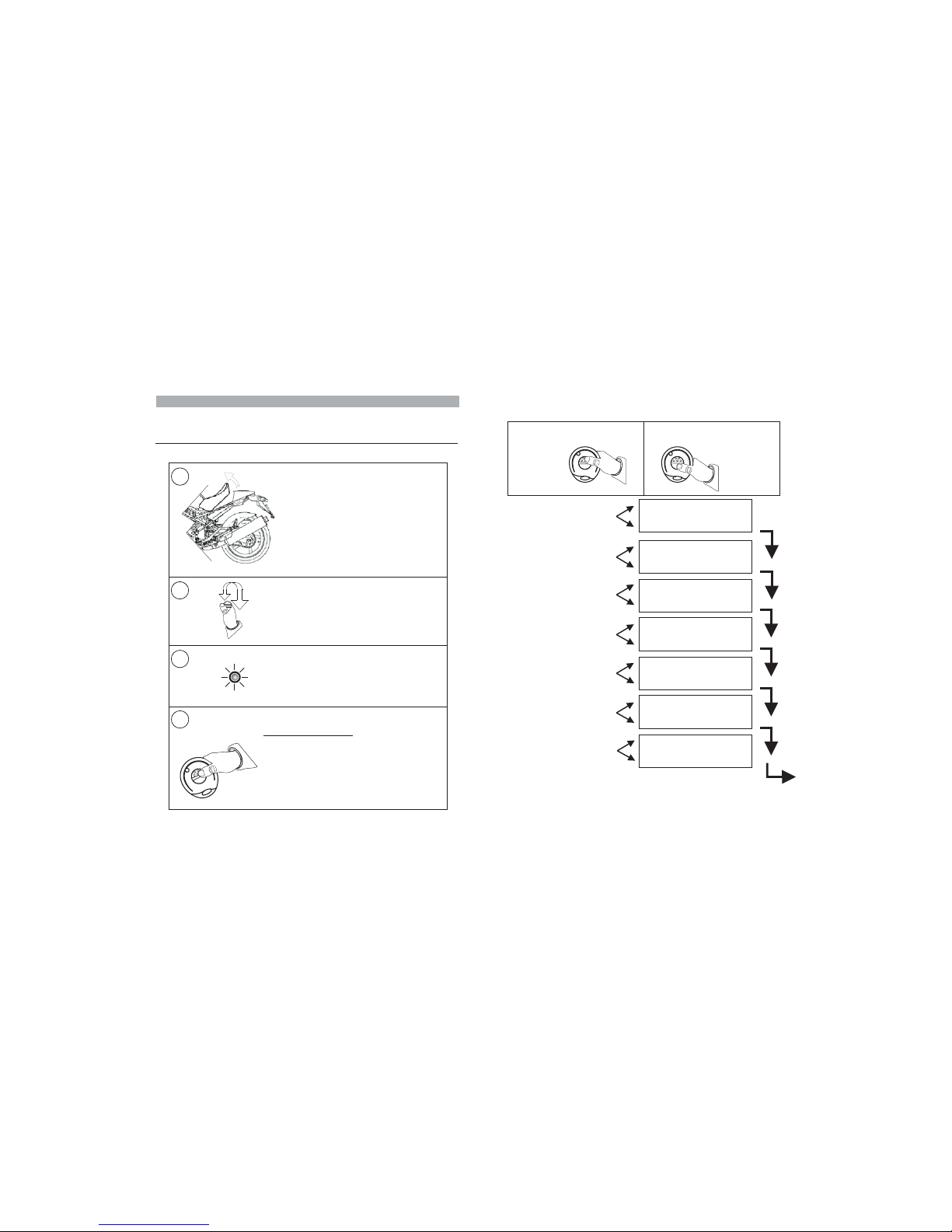
8.0 -PIN CODE OVERRIDE EXAMPLE
To help you understand the override procedure by PIN code, here below is a
step-by-step exampleentering PINcode “2-3-4-1”.
After the alarm warnings are over, the status LED will turn ON steady for
approx. 5 sec. While the LED is ON, cycle ignition key ON and OFF; the
LED will go OFF to confirm the system is in PIN override mode.
After 4 sec. the LED will flash 9 times in sequence. Count the number of
flashes
equals that of the 1st digit .
After 4 sec., there will be another sequence of LED flashes. Cycle ignition
key ON and OFF after the 3rd blink (PIN code 2nd digit “3”).
and cycle ignition key ON and OFF when the number of flashes
(in this case “2”)
Arm the system. After the arming delay, trigger an alarm condition.
Repeat theabove stepsfor the remainingtwo digits(” ).4” and“1”
Key “ON” Key “OFF”
Alarm condition
Key
“OFF”
Key
N“O ”
LED ON
approx. 5”
L OFF to
confirm
override mode
ED
First digit: “2”
Second digit: “3”
“ON” “OFF”
4 Sec.
4 Sec.
4 Sec.
4 Sec.
Third digit: “4”
Fourth
digit: “1”
If the PIN code has been entered correctly, the alarm system will disarm
and signal the last cause of alarm (see par. 3.11).
“ON”
“ON”“ON”
“OFF”
“OFF”“OFF”
If the LED blinks more than 9 times, the procedure will be invalidated and
considered a theft attempt.
Page 8

9.0 - PIN CODE CUSTOMIZATION
Here below is a step-by-step example showing how to customize the factory
PIN code.In thiscase the selectedPIN codeis .2-3-4-1
Ground the BROWN-GREEN wire.
Disconnect the BROWN-GREEN
wire.
Open the seat (if protected by a
contact switch).
Close the seat if previously opened.
Turn ignition key “ON”
.
The status LED will light up for approx.1 sec.
While the LED is ON, simultaneously press both remote control buttons.
2 Beeps will sound and the LED will power ON steady.
D.isarm the alarm system
Key “ON”
1 sec.
Bop
Bop
Steady
ON
GROUND
GROUND
BROWN-GREEN
BROWN-GREEN
PAGE 13 PAGE 14
Bop
Bop
Beep
Simultaneously press both.remote control buttons.
The LED will turn OFF
LED
OFF
LED
OFF
Turn ignition key “OFF”.
After 4 sec., the LED will flash 9 times in sequence.
Count the number of flashes and cycle ignition key ON and OFF when the
number of flashes equals that of the new PIN code 1st digit.
Repeat the above steps to enter the last 2 digits.
When the 4th digit is entered, the system automatically exits the procedure.
2 Bops and 1 Beep will confirm the code has been entered successfully.
After.4 sec., .
2nd digit
there will be another sequence of LED flashes
Repeat the above step to enter the
Key
“OFF”
Key
“ON”
Key
“ON”
Key
“OFF”
Key
“OFF”
Last
digit
LED
OFF
Key
“ON”
Key
“OFF”
Page 9

10.0 - REPLACING REMOTE CONTROL BATTERIES
When theremote control batteriesare too weak(see par.2.0), replace themas
follows:
Separate theremote shellstaking care notto damagethe internal circuit.
Insert thenew batteriestaking care notto invertpolarity.
Close theremote shells.
Make surethe remotecontrol works properly.
!
!
!
!
!
Remove thedischarged batteries.
Use only CR1616 batteries.
There is a serious risk of explosion if batteries are replaced by an
incorrect type.
Different type batteries can also seriously damage the remote control unit.
Discard used batteries properly in special dedicated containers.
BATTERIES
WARNING
!
PAGE15 PAGE 16
12.0 - WASTE ELECTRICAL AND ELECTRONIC EQUIPMENT
(WEEE) DIRECTIVE
The presentdevice does notfall within thescope of Directive2002/96/EC on
Waste Electrical and Electronic Equipment (WEEE) as specified in art. 2.1 of
Leg. Decreen. 151of 25/07/2005.
13.0 - USE AND MAINTENANCE
:
Do notclean thealarm unit withwater butuse a dampcloth towipe.
.
!
Care shouldbe takento protect theelectronic alarmsystem
Do notuse voltagesother than theone specifiedby the manufacturer
Protect thealarm fromany direct waterflow suchas high-powered water
jets foundin acar wash.
!
!
Gemini Technologies will not be held responsible for any damage
caused by improper use.
ATTENTION
!
14.0 - WARRANTY CONDITIONS
n.206
6, 2005 (”Italian Consumer Sales Code”) and subsequent
amendments.
This product is guaranteed for 24 months from the date of purchase in
accordance with the provisions set forth in Leg. Decree dated
September
The productcertificate, dulycompleted and accompaniedby theoriginal sales
receipt willconstitute proofof purchase.
The warranty shall be void if labels on the product or on the certificate are
missing or torn, if the certificate is not fully completed or if the enclosed sales
receipt ismissing.
The manufactureris responsible forany aspectof installation, after-sales
service and/or technical support and, should these services beincluded in the
sales contract,they willbe the exclusiveresponsibility ofthe retailer.
Consumers who need to enforce their statutory consumer guarantee rights
against defective products - in accordance with Art. 128 et seq. of the Italian
Consumer SalesCode (Leg. Decree n.206as above)- must personallycontact
the retailer.
The manufacturer declines any responsibility for eventual malfunctions or
failures of the product and/or any damage whatsoever caused by improper
installation, useor tampering.
This alarmsystem issolely intended tobe atheft-deterrent device.
NOT
Power supply
Power supply range
Current absorption @ 12Vdc
Relay capacity
Current absorption in
Siren sound level
sleep mode
12 Vdc
9Vdc-15Vdc
)
mA
118dBA @1m
8A
< (system armed and LED
flashing
<1
2mA
11.0 - TECHNICAL SPECIFICATIONS
Turn indicator output
12V max. (6A max. per side)
Page 10

INSTALLER MANUAL
15.0 - FITTING INSTRUCTIONS
Please read all instructions and understand them thoroughly before starting
the installation.
The present manual is to be considered an integral part of the alarm
system.
17.0 - ALARM UNIT POSITIONING
Do not install the alarm unit in this
position as water ingress over time
may seep through the rubber sheath
and permanently damage the
electronic circuit making the alarm
unreliable.
Eventual malfunctioning due to water
infiltration is not covered by warranty.
!
!
!
Fitting the alarm in this position will prevent water
entering theunit.
It is important to give the rubber sheath a “
bending as shown in thepicture opposite and
secure witha tiewrap.
Do notexpose toatmospheric agents.
goose-
neck”
!
!
!
!
!
Pay attentionnot tomuffle the siren speaker.
Secure awayfrom movingmechanical parts.
Keep away from devices that could reach high
temperatures whenthe vehicleis in use.
Do not secure the alarm unit directly on the vehicle
frame.
Keep away from devices that could generate high
frequency electromagneticdisturbances.
NO!
OK!
Since the alarm system has a built-in high sensitivity triaxial tilt sensor, it can
be positioned either verticallyor horizontally as long as you keepthe following
:in mind
PAGE17 PAGE 18
Do not jet wash the alarm ECU.
The warranty will not cover damages to the alarm system due to water
ingress caused by improper installation or jet washing.
ATTENTION
!
16.0 - ALARM UNIT SEALING
To seal the alarm, position the
rubber cap over the external edge of
the alarm housing as shown below.
Pull the plastic rectangular flange
over the rubber cap and secure with
the supplied screws.
Do not over tighten the screws.
Alarm unit sealed
Page 11

18.0 - ACCESSORIES
18.1 - STATUS LED
Since the LED warning light serves as both a system status indicator and a
visual deterrentit
Always checkthe rearclearance before drilling:
• Drilla
must beinstalled whereit can readilybe seen.
ø 10mmhole andinsert the LEDholder.
• Gentlypress theLED holder untilit clicksinto place.
• Connectthe LEDBlack 2-pin connectorto thealarm Black 2-pinconnector.
• Bundleup andtie down anyexcess wires.
18.2 - CONTACT SWITCH (OPTIONAL)
A contact switch canbe fitted to protectthe seat or topcase.It must be installed
in such a way as to detect the opening of the seat/topcase without being
accessible fromthe outside.
The triggerthreshold mustbe carefully setto avoidfalse alarms.
Do notground the switch terminal tothe vehicle chassis as it mightnot be earth
grounded. Connect to awire that provides continuous groundsuch as the turn
indicator lampnegative lead.
NB: Ifno contactswitch is fitted,the GREEN/BROWNwire will remainfree for
other possibleuses suchas programming thealarm orlearning new devices.
PAGE 19 PAGE 20
Attach to cut end of key switch wire
Attach to cut end of main wiring harness.
.
Connect to a permanent negative connection
(do not connect to vehicle chassis
Connect to the cable end which, if grounded, will kill
the engine.
).
19.0 - PINOUT TABLE
Wire functionWire colorPos.
-1-
-2-
-3-
-4-
-5-
-6-
-7-
-8-
-9-
-10-
-11-
-12-
-13-
-14-
-15-
-16-
---
Brown
White-Violet
Green-Brown
---
---
Yellow
Black
--Grey
White
White-Grey
Orange
Red
Orange
Black
N/A
Power supply earth ground
Turn indicators (12V, 6A max.)
Positive supply
Turn indicators (12V, 6A max.)
LEARN button / Anti-hijack
N/A
N/A
Ignition
LED
N/A
Contact switch input
Immobilizer (N.C.)
Immobilizer (Com.)
Immobilizer (N.O.)
Antenna
negative output
IMMOBILIZER - wire joint
IMMOBILIZER - grounded wire
Wire color
Wire color
White
Grey
White
White/Grey
Connections
Connections
CAUTION
Alarms are supplied without wiring harnesses. Awide range of specific pinto-pin wiringharnesses isavailable for themost commonmotorbikes.
KITCA 417N17.The following tables refer to the generic wiring harness
18.3 - ANTI-HIJACK BUTTON (OPTIONAL)
Connect the anti-hijack button to the White-Violet wire. The anti-hijack will
trigger whena negativesignal is detected.
ATTENTION
!
This alarm system is intended for 12V turn indicators.
sure the flashers are powered by a
12V signal.
Before you do any electrical work, make
Page 12

Turn indicators
(12V)
Optional fuse
(recommended)
Key
switch
White-Grey
White
Grey
10A
Red
Ground
Battery
12 V
Brown
Yellow
Green-Brown
Immobilizer
White-Violet
16812414610
2
15711313
5
9
1
20.0 - WIRING DIAGRAM
Orange
Orange
Seat/topcase
contact switch
(recommended)
PAGE 21 PAGE 22
Status
LED
21.0 - IMMOBILIZER WIRING DIAGRAM
Key switch
White
Immobilizer wire
Cut
Grey
To vehicle engline
Key switch
White
Immobilizer wire
Ground
White/Grey
To vehicle engine
ENGINE IMMOBILIZER - GROUNDED WIRE
For most small
2-stroke motorcycle engines.
ENGINE IMMOBILIZER - CUT WIRE
Page 13

PAGE 23 PAGE 24
22.0 - DIODE INSTALLATION
Activate oneof theturn indicators, turnignition keyOFF and armthe alarm.
If the instrument panel lights up when the turn indicators are activated, a
diode needsto beinstalled (follow diagrambelow).
!
How totell ifyou need toinstall adiode:
!
Vehicle wiring harness
After
Turn indicator
relay
WHITE wire
Cut
Diode installed
in-line
Vehicle original
wire
Live feed to
turn indicators
BLACK wire
Before
CAUTION
23.0 - LEARNING NEW DEVICES
The alarm system is supplied with 2 remotecontrols but extra remotes canbe
added.
Tolearn new devices, make sure passive arming is NOT enabled. Proceed as follows:
Alarm memory will only store 8 devices.
Saving an extra device will automatically delete the first one.
23.1 -BY GROUNDINGTHE BROWN/GREEN WIRE:
!
!
Disarm thealarm systemvia remote control.
Lift the seat or open the topcase (if fitted with a contact switch) otherwise
ground theBROWN/GREEN wire.
! Groundthe White-Violet wire (somewill have a Yellowend connector).
!
!
!
!
!
Turn ignition key inON.
Press oneof thebuttons on theremote controlto be learned.
A flash of the turn indicators and a Beep will confirm the new remote has
been learned.
If other remote controls need to be learned,
then pressthe buttonon the .
Toexit the learn procedure, turn ignition key OFF. A Bop and a single flash
of theturn indicatorswill confirm theend ofthe procedure.
Close the seat/topcase or remove the BROWN/GREEN wire from
ground.
!
!
!
Disconnect theWhite-Violet wire.
repeat the above procedure
remote controlto belearned
2 flashesof the turnindicators and 2confirmation tones (1Bop and 1Beep)
will acknowledgethe systemis in learnmode.
23.2 - WITHOUT GROUNDING THE BROWN/GREEN WIRE:
!
!
!
!
Disarm thealarm systemvia remote control.
Turn ignition key inON.
.
If other remotes need to be learned, wait 2 sec. and then press one of the
buttons onthe remotecontrol to belearned.
Toexit thelearn procedure, turnignition keyOFF.
!
!
The status LED will light up for 1 sec.;while the LED is ON, simultaneously
press bothbuttons onthe remote control.
2 flashes of theturn indicators and 2 confirmation tones (1Bopand 1 Beep)
will acknowledgethe systemis in learnmode.
!
!
Press oneof thebuttons on theremote controlto be learned
A Bop and a single flash of the turn indicators will confirm the end of the
procedure.
Page 14
PAG E 2 6
After pressing both buttons simultaneously (step 4), program the features
according toyour needs.
EXIT PROGRAMMING
24.0 - PROGRAMMABLE FEATURES
To either enable or disable one of the programmable features, proceed as
follows:
NB: Rememberto ALWAYS arm/disarmthe system before programming.
4
2
3
With the system disarmed, lift the seat
or open the topcase (if protected by a
contact switch) otherwise ground the
GREEN/BROWN wire.
NB: Remove the wire from ground after
programming.
Turn ignition key in ON.
The status LED will light up for approx. 1 sec.
While the LED is ON, simultaneously press
both remote control buttons.
Two confirmation tones (1 Bop and 1 Beep)
will acknowledge the system is in
programming mode.
The LED will light up steady.
1
Button ENABLE
Button DISABLE
1:
2:
Button 1: ENABLE
2: DISABLEButton
Button ENABLE
Button DISABLE
1:
2:
Button ENABLE
Button DISABLE
1:
2:
Button ENABLE
Button DISABLE
1:
2:
Button ENABLE
Button DISABLE
1:
2:
Button ENABLE
Button DISABLE
1:
2:
PANIC
()
ALARM
factory enabled
ACOUSTIC SIGNALS
(factory enabled)
TILT SENSOR
(factory enabled)
SYSTEM SELF-REARMING
()factory disabled
PASSIVE ARMING
()factory disabled
ANTI-HIJACK
()factory disabled
PRE-ALARM
()factory disabled
TO ENABLE
TO DISABLE
Press button 1
Press button 2
PAGE 25
Page 15

CAUTION
25.0 - PROGRAMMING EXAMPLE
Here below is a step-by-step example showing how to program the system
with theacoustic signals,the panic alarmand thepre-alarm features enabled.
.
Keep inmind that, at every buttonpress, thesystem automatically scrolls tothe
next feature.
With the system disarmed, lift the seat/topcase (if protected by a contact
switch) otherwiseground theBROWN/GREEN wire.
Turn ignition key inON; theLED will lightup forapprox. 1 sec.
While the LED is ON, simultaneously press both remote control buttons; 2
Beeps will confirm the system is in programming mode. The LED will also
light upsteady.
Press remote control button 1; a Beep will confirm have
been enabled.
; a Beep will confirm thatthe has
been enabled.
Press button 2; a Bop will confirm that has not been
enabled.
Press button2; a Bop will confirmthat the has notbeen
enabled.
Press button 1; a Beep will confirm that the has been
enabled.
Press button2; aBop will confirmthat has notbeen enabled.
When the last feature has been configured, the system automatically exits
the programming procedure; 2 Bopsand 1 Beep will confirm the end of the
procedure. The statusLED willpower OFF.
Turn ignition key OFF, close the seat/topcase or remove the BROWNGREEN wirefrom ground.
!
!
!
!
!
acoustic signals
panic alarm
passive arming
anti-hijack feature
pre-alarm feature
self-rearming
!
!
!
!
!
!
Press remote control button 1
Press button2; a Bop will confirmthat the has beendisabled.tilt sensor
You can exit the programming procedure at any time by turning ignition
key OFF.
Programmed features will automatically be saved while the others will
remain unvaried.
PAGE 27
26.0 - TILT SENSOR ADJUSTMENT
The alarm system has a built-in triaxial tilt/shock sensor with 4 levels of
sensitivity adjustment. T e shock sensor is factory preset to be at minimum
sensitivity.
Tochange thesensitivity level proceedas follows:
Disarm thealarm systemvia
Lift theseat/topcase (if protected by acontact switch) otherwiseground the
BROWN/GREEN wire.
.
!
!
!
h
remote control.
Turn ignition key ON;the statusLED will turnON forapprox. 1 sec
! While the LED is ON, press remote control button 2 and press it again within 2 sec.
CAUTION
The procedure will be voided if more than 2 seconds go by between the
first button press and the second.
!
!
Two LED flashes and two Beeps will confirm the system is in adjustment
mode.
Sensor isat thelowest sensitivity level.
!
!
!
!
Press remote control button 2 to increase sensitivity by one (press 3 times
to set at maximum level); a LED flash and a Beep will confirm each change
of setting.
When thesensor isadjusted, turn ignitionkey OFF.
If adjusted at the highest level (3 button presses), the system automatically
exits theprocedure.
In bothcases, aLED flash andBeep willconfirm the endof theprocedure.
!.Turn ignition key OFF. Close the topcase/seat or remove the
BROWN/GREEN wirefrom ground
CAUTION
Every time you enter the programming procedure, sensitivity is restored to
the factory default setting.
PAG E 2 8
Page 16

Company
Address, City
Country
Phone number
Fax number
Art. of Directive
3.1 (a) Health
3.1 (a) Safety
3.1 (b) EMC
3.1 (b) EMC
Art. of Directive
3.2 Spectrum
Product description:
Intended use:
EU / EFTA member states intended
for use
Member states with restrictive use
Manufacturer
Brand name
Type / Model
GEMINI TECHNOLOGIES S.r.l
Via Luigi Galvani 12, 21020 Bodio Lomnago (VA)
Italy
+39 0332 943211
+39 0332 948080
Standard
EN 50371
EN 60950-1 +A11
EN 301 489-3
E 301 489-1
N
Standard
EN300 220-2
TCF reference n°
Date
Name and position
Date of issue
2002
2006; 2009
V2.1.1 (2009-05)
V1.8.1 (2008-04)
Date of issue
V2.3.1 (2010-02)
TCF_ 7208E/7218E
August 23, 2010
Andrea Rossi, Managing Director
Remote control at 433,92 Mhz
For vehicle alarm systems
EU: all members
EFTA: all members
None
GEMINI TECHNOLOGIES S.r.l.
GEMINI
7208E and 7218E
We, the undersigned,
R&TTE Declaration of Conformity
Doc ref. No. 2010-01
Declare underour soleresponsibility that thefollowing equipment:
Is tested to and conforms with the essential requirements of Art. 3.1 (a) for protection of
Health andSafety of theuser and anyother person and of Art. 3.1(b) for Electromagnetic
Compatibility,as included inthe followingstandards:
And is tested to and conforms to Art. 3.2, with the essential radio test suites so that it
effectively uses the frequency spectrum allocated to terrestrial/space radio
communication and orbital resources so as to avoid harmful interference, as included in
the followingstandards:
And therefore complies with the essential requirements and provisions of
of the European Parliament and of the Council of March 9, 1999 on radio
equipment and telecommunications terminal equipment and the mutual recognition of
their conformityand withthe provisions ofAnnex II.
Directive
199/5/EC
NOTES
 Loading...