

Page 1

AC 2711UK Rev. 06 - 10/14
UK
INSTALLATION AND
USE MANUAL
Made in Italy
SERIE 823
823
822
Page 2

1.0
2.0
4.0
5.0
6.0
7.0
8.0
15.0
16.0
17.0
- PRELIMINARY ADVICE.............................................................................................
- OPERATION...............................................................................................................
2.1 - Complete system arming.........................................................................................
2.2 - System arming with sensor and comfort control exclusion......................................
2.3 - Passive arming.........................................................................................................
2.4 - Arming inhibit time....................................................................................................
2.5 - System armed..........................................................................................................
2.6 - Alarm, inhibit time between alarms and alarm cycles..............................................
2.7 - System disarming.....................................................................................................
2.8 - Emergency disarming by electronic key...................................................................
2.9 - Alarm memory..........................................................................................................
WARRANTY CONDITIONS ...................................
- WASTE ELECTRICAL AND ELECTRONIC EQUIPMENT (WEEE) DIRECTIVE.......
- PIN-OUT TABLES......................................................................................................
5.1 - 20-pin connector.......................................................................................................
5.2 - 8-pin connector.........................................................................................................
- COMPLETE ELECTRIC DIAGRAM...........................................................................
- .......................
..........................................................................................
..........................................................
7.3 - Connections to Hazard switch..................................................................................
- CENTRAL LOCKING CONNECTIONS TO ARM/DISARM THE SYSTEM.................
...........................................
...........................................................
8.3 - Connections to turn indicators..................................................................................
SYSTEM PROGRAMMING.............. ....................................
........................................................................................
.........................................................................
10.3 - Passive arming.......................................................................................................
10.4 - 5) ...........................................................................
10.5 - Boot switch polarity selection.................................................................................
10.6 - Optical pulse
..................
..............................................
DIP-SWITCHES PROGRAMMING TABLE...............................................................
..........................................................
..........................................................................
.........................................................................................
.........................................................................
- ..................................................................
- SYSTEM ............................................................................................
- TECHNICAL SPECIFICATIONS...............................................................................
USER MANUAL
INSTALLER MANUAL
3.0
9.0
10.0
11.0
12.0
13.0
14.0
- .....................................................
CONNECTIONS FOR ARMING VIA TURN INDICATORS..................
7.1 - Standard connections.....
7.2 - Connections for vehicles with separate lines..
8.1 - Connections to actuators with separate radio receiver..
8.2 - Connections to actuators with lock switches.
- SELF-LEARNING OF TURN INDICATOR FLASHES................................................
- ....................................
10.1 - Visual signalling..............
10.2 - Audio signalling..............................
Arming of siren (art. 772 output
signal/self-powered siren..................................................................
10.7 - Negative output selection (during alarm) for horn or additional siren...
- SYSTEM PROGRAMMING EXAMPLE......................
-
- ULTRASONIC VOLUMETRIC PROTECTION
13.1 - Connections and positioning........
13.2 - Sensor adjustment.........
- ADDING NEW DEVICES.................
DELETING PROGRAMMED DEVICES.
RESET..........
PAGE 02
PAGE
PAGE
PAGE
PAGE
PAGE
PAGE
PAGE
PAGE
PAGE
PAGE
PAGE
PAGE
PAGE
PAGE
PAGE
PAGE
PAGE
PAGE
PAGE
PAGE
PAGE
PAGE
PAGE
PAGE
PAGE
PAGE
PAGE
PAGE
PAGE
PAGE
PAGE
PAGE
PAGE
PAGE
PAGE
PAGE
PAGE
PAGE
PAGE
PAGE
PAGE
PAGE
PAGE
TABLE OF CONTENTS
UK
Page 3
1.0 - PRELIMINARY ADVICE
Dear Customer, th
.
same as 823 without self-powered battery.GEMINI 822:
e present manual illustrates the top version of the alarm system; not all functions,
electrical connections etc. will therefore apply to all models.
Before installing, identify your alarm model and refer to it for the correct instructions
The following signs, intended for the installer or the user, indicate particular functions or connections
as follows:
USER MANUAL - PAGE 03
For the user.
This sign highlights useful information.
For the installer.
This sign indicates that the functionning of the alarm can vary according to connections
and programming of the system or it simply provides useful indications for the
installation.
!
2.0 -
2.1 -
2.2 -
.
System arming is confirmed by a siren chirp (if feature status has been modified) and a flash of the turn
indicators.
The system has a 30” pre-arming “neutral time” (indicated by the LED turned ON steady).
lose vehicle doors and press the
lock button on the original remote control
.
OPERATION
COMPLETE SYSTEM ARMING
SYSTEM ARMING WITH SENSOR AND COMFORT CONTROL EXCLUSION
Press the lock button on the original remote control of the vehicle
This function allows arming the system while excluding internal volumetric protection, external
sensors (infrared wireless) and comfort feature.
To activate this function, the system should be disarmed and the ignition key turned to the “OFF”
position; proceed as follows.
With doors opened: insert the electronic key into its receptacle, c
.
In both cases the system will be armed but only in the second case will the vehicle be also locked
!
!
Sensors and comfort function exclusion is bound to each single arming cycle.
USER MANUAL
2.3 -
If this function is programmed, the system passively arms approx. 60” after switching ignition OFF and
after opening and closing the last door.
System activation will be confirmed by the regular optical/acoustic arming signal.
PASSIVE ARMING
In case of passive arming, internal sensors and comfort output (automatic window roll-
up) will be excluded.
Opening a door 60” before the system is armed temporarily interrupts the procedure
which will resume once the door is closed.
Page 4
PAGE 04 - USER MANUAL
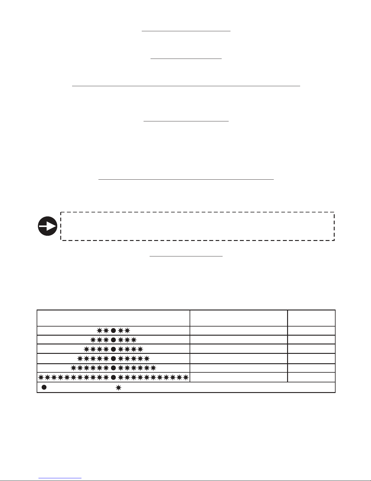
2.9 - ALARM MEMORY
(siren chirps, )
.
Five flashes of the turn indicators and five beeps if feature status has been modified
upon disarming warn that the alarm has been triggered in your absence.
Toidentify the last cause of alarm , turn ignition ON and count the number of flashes of the status LED.
Optical signals are repeated 3 times in a row; to interrupt, turn ignition key “OFF”.
The table below lists the various alarm causes and relative number of LED flashes
LED FLASHES ALARM CAUSES
ALARM
CYCLES
10
10
10
10
10
10
Ignition attempt (+15/54)
Door opening
Bonnet opening
Boot opening
Volumetric or external sensor
Wire tampering
LED ON (1 second)LED OFF (2 seconds)
To restore normal operation, touch the electronic key to its receptacle.
A quick chirp and a flash of the status LED will confirm that the system is back to normal
mode.
2.4 -
s by optical/acoustic signals.
After an alarm is triggered, but
.
Disarming is confirmed by 2 siren chirps (if feature status has been modified) and 2 flashes of the turn
indicators.
An alarm condition is signalled by 5 acoustic signals (if feature status has been modified) and 5 flashes
of the turn indicators.
The various alarm causes and relative LED aragraph
mode is used for “EMERGENCY DISARMING” and “TOTAL DISARMING”.
Touching the electronic key to its receptable disarms and switches off the system which will not rearm
if the remote control is used
ARMING INHIBIT TIME
2.5 - SYSTEM ARMED
2.6 - ALARM, INHIBIT TIME BETWEEN ALARMS AND ALARM CYCLES
2.7 - SYSTEM DISARMING
2.8 - EMERGENCY DISARMING BY ELECTRONIC KEY
The inhibit arming time lasts approximately 30” and is indicated by the LED turned ON;
.
After the inhibit time the system is “armed” and ready to detect any theft attempt. When the system is
fully armed, the LED flashes.
The system will indicate theft attempt
before another alarm cycle starts, there is a 5 sec. “neutral time”.
An alarm event can generate up to 10 alarm cycles of 30” each for each input and for each arming cycle.
Press the unlock button on the vehicle original remote control
signals are detailed in p (2.9).
This disarming
.
it is possible to
exit the vehicle without triggering any alarm
Page 5

USER MANUAL - PAGE 05
3.0 - WARRANTY CONDITIONS
This.product is guaranteed to be free from manufacturing defects for a period of 24 months from the
installation date shown on this warranty, in compliance with the Directive 1999/44/CE.
Please fill-in entirely the guarantee certificate included in this booklet and do NOT REMOVE the
guarantee label from the device.
The warranty will become void if labels are missing or torn, if the installation certificate is not full
y
compiled or if the enclosed sale document is missing.
The guarantee is valid exclusively at authorized Gemini Technologies S.p.A. Service Centers.
The manufacturer declines any responsibility for eventual malfunctions of the device or any damage
to the vehicle electrical system due to improper installation, use or tampering.
This alarm system is solely intended to be a theft-deterrent device
4.0 - WASTE ELECTRICAL AND ELECTRONIC EQUIPMENT
(WEEE) DIRECTIVE
The present device does not fall within the scope of Directive 2002/96/EC on Waste Electrical and
Electronic Equipment (WEEE) as specified in art. 2.1 of L.D. no. 151 of 25/07/2005.
Page 6

WHITE-ORANGE wires must ALWAYS be connected if system is to operate via
the turn indicators.
!
PAGE 06 - INSTALLER MANUAL
Negative Input - door lock switch signal
Arming signal
Disarming signal
Positive/negative input - boot switch
Negative input - door switches
Input - electronic key receptacle
Ground - receptacle for electronic key
LED negative output
LED positive output
Ignition
Positive input - door lock switch signal
Programmable input - door lock switch signal
Positive output with system armed (+A)
Negative input - external sensors
Negative input - bonnet switch
Output - self-powered siren (lack of negative during alarm) or
impulse visual signalling
Comfort negative output
Negative output - additional siren or horn
Antenna
Learn input and system arm/disarm via turn indicators
Ground
Siren output
Positive
Turn indicators positive output
Engine lock
Siren output
Engine lock
Turn indicators positive output
-1-
-2-
-3-
-4-
-5-
-6-
-7-
-8-
-9-
-10-
-11-
-12-
-13-
-14-
-15-
-16-
-17-
-18-
-19-
-20-
-1-
-2-
-3-
-4-
-5-
-6-
-7-
-8-
BLACK marked “M”
-----
BLACK marked “R”
ORANGE
BLACK marked “H”
-----
BLACK marked “H”
ORANGE
WIRE FUNCTIONPOSITION
WIRE COLOUR
5.2 - 8-PIN CONNECTOR
WIRE FUNCTIONPOSITION
WIRE COLOUR
5.0 - PINOUT TABLES
5.1 - 20-PIN CONNECTOR
INSTALLER MANUAL
YELLOW-RED
YELLOW-BLUE
GREEN-BLUE
GREEN-WHITE
GREEN-BROWN
GREEN
BROWN
BLACK
RED
BLACK marked “G”
RED-BROWN
WHITE-LIGHT BLUE
PINK
GREEN-BLACK
GREEN
BLUE
WHITE-BLACK
YELLOW-BLACK
BLACK
WHITE-ORANGE
Page 7
INSTALLER MANUAL - PAGE 07
15A
+
Battery
8A
MAX !
POSITIVE
BLACK marked “R”
WHITE-ORANGE
Input - system operating via turn indicators
+30
BLACK marked “H”
BLACK marked “H”
Engine lock
ELECTRONIC KEY
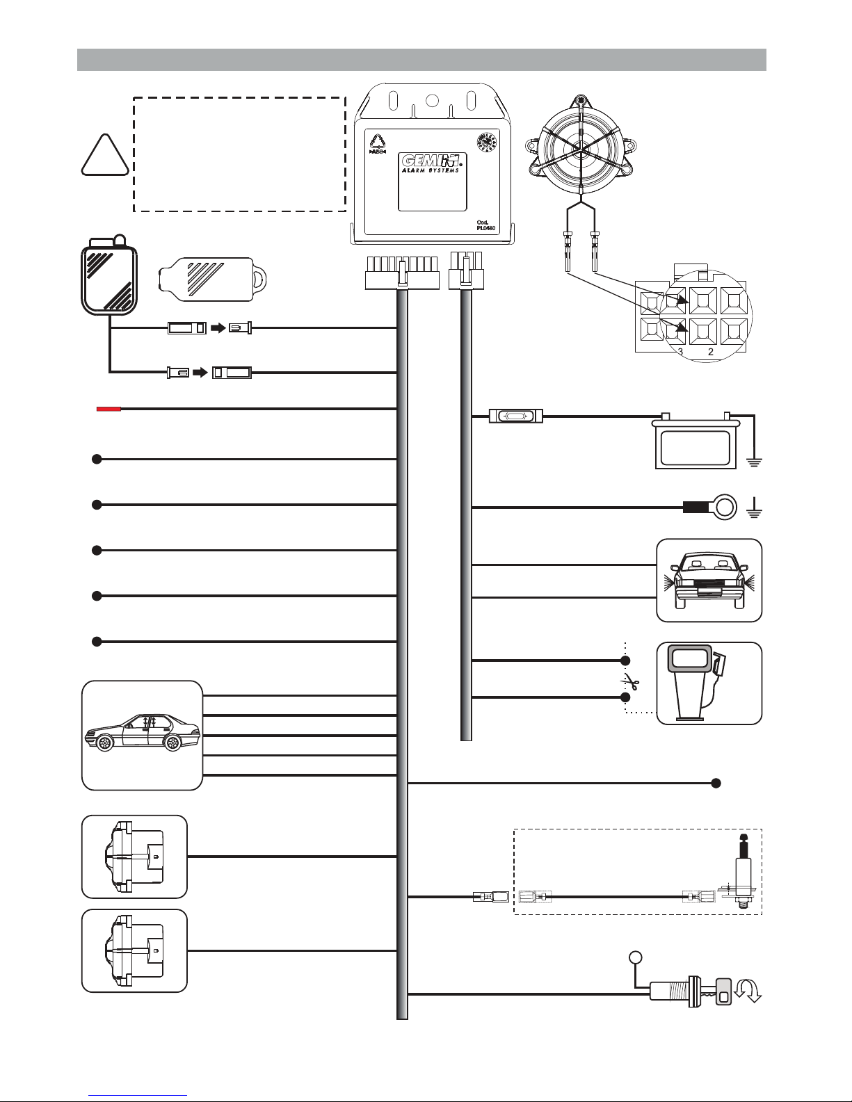
6.0 - COMPLETE ELECTRIC DIAGRAM
Connection
of unit 823
(with siren)
Disconnect the negative
battery terminal before
carrying out electrical
connections.
Reconnect ONLY after you
are done.
!
1
5
234
8
BLUE
Self-powered siren output
(art. 7725, negative
in alarm
lack of
) or Hazard pulse
Red
Black
Green
Brown
Antenna, do not tamper
BLACK
External sensor negative input
Door switches input
Boot switch input
Comfort negative output
Positive with system armed (+A)
GREEN-BLACK
GREEN-BROWN
GREEN-WHITE
WHITE-BLACK
PINK
YELLOW-BLACK
Horn/Supplementary siren
(negative output in alarm)
BLACK marked “G”
Ignition
ORANGE
ORANGE
Turn indicators output
BLACK marked “M”
GROUND
WHITE-BLUE
YELLOW-BLUE
YELLOW-RED
See CDL diagrams
RED-BROWN
GREEN-BLUE
OPTIONAL
GREEN
Bonnet switch
Page 8

GEMINI 823
SYSTEM
GEMINI 823
SYSTEM
GEMINI 823
SYSTEM
RIGHT TURN
INDICATORS
LEFT TURN
INDICATORS
ORANGE
WHITE-ORANGE
ORANGE
TURN INDICATORS
CONTROL UNIT
ORANGE
WHITE-ORANGE
ORANGE
7.2 - CONNECTIONS FOR VEHICLES WITH SEPARATE LINES
7.3 - CONNECTION TO HAZARD SWITCH
VEHICLE
WIRING
CIRCUIT
BLUE
WHITE-ORANGE wire must ONLY be
connected if the system is to be
armed/disarmed via the turn indicators.
WHITE-ORANGE wire must ONLY be
connected if the system is to be
armed/disarmed via turn indicators.
Add 6
2 Amp. diodes.
Select “optical pulse signals”
in the “SYSTEM
PROGRAMMING” menu.
Do not make this connection
if the system is to operate
via turn indicators.
Front
LH
Rear
RH
Side
LH
Side
RH
Rear
LH
Front
RH
PAGE 08 - INSTALLER MANUAL
7.0 -
7.1 - STANDARD CONNECTION
CONNECTIONS FOR ARMING VIA TURN INDICATORS
Page 9

INSTALLER MANUAL - PAGE 09
8.0 - CENTRAL LOCKING CONNECTIONS TO ARM/DISARM THE SYSTEM
.
“ON”.
“C”,
“D”, “E” connection).
“ON”.
8.1 -
8.2 -
8.3 - CONNECTIONS TO TURN INDICATORS
Central door locking must be connected according to vehicle type (see installation schemes). Check
out the various possibilities described below and proceed with the applicable connection.
Arming via the lock actuators.
Arming via the lock actuators and the lock/unlock switches.
Arming via the turn indicator flashes.
Arming via the turn indicator flashes and the lock actuators.
Arming via the turn indicators flashes, the actuators and the lock/unlock switches
Arm/disarm connections for vehicles with a radio receiver that is separate from CDL (see www.geminialarm.com for diagram “A” connection).
Set dip-switch nr. 4
Arming/disarming connections for vehicles that require connections to actuators but also require
control of lock switches or internal lock/unlock switches (see www.gemini-alarm.com for diagram
Set dip-switch N. 4
!
!
!
!
!
CONNECTIONS TO ACTUATORS WITH A SEPARATE RADIO RECEIVER
CONNECTIONS TO ACTUATORS WITH LOCK SWITCHES
If the turn indicators lock/unlock flashes are identical, connect the actuators.
If the turn indicators flash when unlocking via the car mechanical key, do not make this
connection.
!
The arm/disarm connection is made by connecting the WHITE-ORANGE wire to the turn indicators.
If the arm/disarm connection is only via the turn indicators, set dip-switch N. 4 “OFF”.
If the arm/disarm connection is via the turn indicators and the actuators, set dip-switch N. 4 “ON”.
9.0 - SELF-LEARNING OF TURN INDICATOR FLASHES
In order to arm/disarm via the turn indicators, the system must learn the vehicle lock (arming) and
unlock (disarming) flashes.
Connect the WHITE-ORANGE wire to the turn indicators and proceed as follows
Disconnect the 8-pin harness connector from the 8-pin alarm connector
Turn ignition key
Connect the 8-pin harness connector to the 8-pin alarm connector; the LED will turn ON steady
urn ignition key lose all doors and press the lock button on the original remote control
When the turn indicators stop flashing, a high-pitched acoustic signal confirms the learning of the
arming flashes
Press the unlock button on the original remote control
When the turn indicators stop flashing, 2 high-pitched audio signals confirm the learning of the
disarming flashes
This completes the procedure
:
.
“ON”.
.
T “OFF”, c .
.
.
.
.
!
!
!
!
!
!
!
!
Page 10

PAGE 10 - INSTALLER MANUAL
10.0 - SYSTEM PROGRAMMING
The t
E .
able below applies to the system programmed in “standard configuration”.
very time you enter the programming procedure, the alarm resets to the default settings
When the optical pulse signaling feature is activated, the blinkers will ONLY emit optical
signals during an alarm cycle.
The system BLUE wire MUST be connected to the Hazard button.
In this case, do not connect the ORANGE wires (see chapter 7.3).
!
FUNCTION STATUS LED FLASHES
Disabled
Enabled
D
D
D
D
D
isabled
isabled
isabled
isabled
isabled
Exclusion of arm/disarm optic signals
Exclusion of arm/disarm acoustic signals
System passive arming
Arming of self-powered coded siren
Boot input, positive signal
Optical pulse signalling
Pulse negative output during alarm cycle
Alack of power during electrical system maintenance will not affect the programming.
The procedure must be carried out entirely. To scroll from one function to another either turn the key to
disable it or use the electronic key to enable the function (see par.11.0).
Programmable functions are briefly described below.
This function activates optic signals when the system is armed and disarmed.
10.1 - OPTICAL SIGNALS
If the vehicle already has optical lock/unlock signals, the turn indicators alarm flashes
should be deactivated.
10.2 - ACOUSTIC SIGNALS
10.3 - PASSIVE ARMING
10.4 - ENABL
10.5 - BOOT SWITCH POLARITY SELECTION
10.6 - OPTICAL PULSE SIGNAL/SELF-POWERED SIREN
This function activates acoustic signals when the system is armed and disarmed.
.
(art. 7725).
This function modifies the alarm input signal (positive or negative) according to the signal generated
.
This function activates the optical
).
This function arms the system 60” after ignition is switched off and the last door is opened and closed.
If a door is opened during this lapse of time, the procedure is interrupted; it will resume when the door
is closed
by the boot switch
signals according to the connection made; only for vehicles where
the hook-up is to the “emergency” switch wire (Hazard button
ING OF SIREN (7725) OUTPUT
This function enables the relative output (20-pin connector, position 13, PINK wire) to activate the selfpowered coded siren
!
If the function is disabled, under normal operating conditions, the blue wire carries a negative signal;
during an alarm cycle, there is a lack of negative.
Page 11

INSTALLER MANUAL - PAGE 11
10.7 -).NEGATIVE OUTPUT SELECTION (DURING ALARM) FOR HORNS OR ADDITIONAL
SIREN
Depending on the connection made, this function can activate the output for the siren (continuous
tone) or for the horn (intermittent tone
11.0 - SYSTEM PROGRAMMING EXAMPLE
10.0).
The following example illustrates the steps to follow to modify the programmable functions.
As mentioned before, turning the key OFF/ON disables the function, while using the electronic key
enables it. To confirm the operation, a high or low pitched signal will sound and the LED will flash as
indicated (see table, chapter
In both cases, the system moves on to the next function.
signals
Repeat steps above to enable or disable
all the other functions.
When the last function is configured (either with the electronic key or the ignition key), in addition
to the confirmation tone, the system gives 2 low-pitched and 1 high-pitched acoustic and
the turn indicators flash twice to confirm the end of the programming procedure.
With alarm system disarmed, turn ignition key “ON”.
ON
Two acoustic signals (a high and a low-pitched beep) and 2 flashes of the turn indicators will
confirm that the system has entered in programming mode.
OFF-ON
Boop
Beep
Turn ignition “OFF” and then back “ON” to
disable the function.
A low-pitched acoustic signal will confirm the
operation.
The LED will flash according to the selected
function (from 1 to 7).
OR
To enable the function, touch the electronic key
once to its receptacle.
A high-pitched acoustic signal will confirm the
operation.
The LED will flash according to the selected
function (from 1 to 7).
The LED will light up for about 2 seconds; during this period.touch the electronic key to its
receptacle
Page 12

12.0 - DIP-SWITCHES PROGRAMMING TABLE
Nr. POSITION FUNCTION
ON
OFF
ON
OFF
ON
OFF
ON
OFF
POSITIVE polarity for control on WHITE/LIGHT BLUE wire
NEGATIVE polarity for control on WHITE/LIGHT BLUE wire
Positive signal (+A) on BROWN/RED with alarm ON
Standard operation
Negative output to arm/disarm the system
Positive output to arm/disarm the system
Arming/disarming via actuators or via actuators and turn indicators
(See par. 8.0)
Arming/disarming only via turn indicators
1
1
2
2
3
3
4
4
Set dip-switches BEFORE connecting the alarm system.
If settings must be modified after installation, FIRST disconnect the alarm and then
reset the dip-switches.
With dip-switch N.2 set to “ON”, the YELLOW-RED wire is grounded when the system is
armed. Leave dip-switch in this position when connecting only the WHITE-LIGHT BLUE
wire to the lock switch (grounded), with vehicle closed.
!
!
13.0 -
13.1 - CONNECTIONS AND POSITIONING
13.2 - SENSOR ADJUSTMENT
Insert the WHITE connector
.
T:
.
ULTRASONIC VOLUMETRIC PROTECTION
in the the “W” socket on the control unit.
Insert the RED connector in the “R” socket on the control unit.
Install the ultrasonic sensors on the top part of the windshield internal pillars, away from the air vents
and point them towards the center of the rear window
o check sensor sensitivity level proceed as follows
With the alarm system disarmed, roll down the front window approx. 20 cm.
Set the trimmer to an intermediate position (medium sensitivity).
Close all doors, bonnet and boot and arm the system.
During the pre-arming delay time, introduce an object in the cabin through the window and move it
around; the status LED will turn off to signal a presence.
If the sensitity lelvel is too high or too low, readjust the trimmer and repeat the above procedure
!
!
!
!
!
ULTRASONIC
CELLS
CONNECTIONS
SENSITIVITY
ADJUSTMENT
PAGE 12 - INSTALLER MANUAL
Page 13

INSTALLER MANUAL - PAGE 13
To carry out the operation successfully, make sure the required electrical connections
(door/bonnet switches and ignition) are complete.
!
!
14.0 - ADDING NEW DEVICES
Storing memory is for 55 devices
If an extra device is added, it will automatically delete the first device programmed in the
system memory..
!
To activate the procedure proceed as follows:
With the system disarmed, open the driver door and the bonnet and leave them open! .
!
!
!
Turn ignition key “ON-OFF”-“ON-OFF”-“ON-OFF”-“ON”.
At the fourth turn, leave it “ON”.
.
To confirm it has entered in learning mode, the system gives 2 acoustic signals (one high and one
low-pitched), the turn indicators flash once and the status LED turns ON
The following operations must be carried out within 4 seconds otherwise the procedure
is invalidated.
Do not close the bonnet otherwise all previously programmed devices will be erased
as described in the next paragraph.
!
!
!
!
!
!
!
The system is ready to receive the device codes.
.
.
R
“OFF”.
T
Insert the electronic key into its receptacle
Each time a device is learned a high-pitched signal sounds and the status LED turns OFF briefly
epeat this procedure to program other devices.
Turn ignition key
o confirm the end of the procedure, a low-pitched signal sounds, the turn indicators flash once and
the status LED turns OFF.
Page 14

PAGE 14 - INSTALLER MANUAL
To carry out the operation successfully, make sure the required electrical connections
(door/bonnet switches and ignition) are complete.
Any previously programmed device can be erased as follows
With the system disarmed, open the driver door and the bonnet and leave them open..!
!
!
!
!
!
Turn ignition key “ON-OFF”-“ON-OFF”-“ON-OFF”-“ON”.
At the fourth turn, leave it “ON”.
.
Close the bonnet.
.
To confirm it has entered in delete mode, the system gives 2 acoustic signals (one high and one
low-pitched sound), the turn indicators flash once and the status LED turns ON
Keep the bonnet closed (approx. 8 sec.) until the devices are completely deleted
The following operations must be carried out within 4 seconds otherwise the
procedure is invalidated.
If the bonnet is opened before 8 seconds, the devices will not be
deleted.
!
!
.
”.
The status LED turns OFF when the devices have been deleted
Turn ignition key “OFF
The end of the procedure is confirmed by a long low-pitched acoustic signal.!
15.0 - DELETING PROGRAMMED DEVICES
!
!
!
Page 15

INSTALLER MANUAL - PAGE 15
To reset the system proceed as follows:
Switch-off the power supply
hort-circuit the RED and BLACK wires of the 2-pin connector
Switch the ; once the alarm system is powered, 4 acoustic signals will sound and the
turn indicators will flash 4 times
Remove the previously created short-circuit; the status LED lights up steady.
reset is confirmed by an aucoustic signal and the wailing of the siren for
approx. 3 seconds
the LED will turn OFF. There are no acoustic signals
!
!
!
!
!
!
system .
S LED .
system ON
.
Turn ignition key “ON”;
.
Turn ignition key “OFF”; .
16.0 - SYSTEM RESET
By activating the following procedure, the system returns to the factory default settings.
This procedure must therefore only be used in case of need, before programming the
system or auto-learning the turn indicator flashes.
!
17.0 - TECHNICAL SPECIFICATIONS
Power supply 823 - 822
Current absorption @ 12Vdc with system armed and LED flashing
Working temperature range
Turn signals relay contact capacity
Engine immobiliser relay contact capacity
Alarm cycle duration
Maximum positive current output when armed (+A)
Additional siren output current capacity
12 Vdc
15mA
From -30°C to +70°C
8 A at 20°C
8 A at 20°C
30 sec.
700 mA
1A
Page 16

7 Dudley Court , Jessop Close, Clacton-on-Sea, Essex, CO15 4LY
TEL: +44 (0) 1255 434353
Email: sales@avsgemini.com | Web: www.avsgemini.com
UK Distributors of the Gemini Alarm Systems
 Loading...