


ApexPro
™
Telemetry System
Operator’s Manual
Software Version 3
2001989-134 Revision D

NOTE:
The information in this manual only applies to ApexPro Telemetry System software version 3. It does not
apply to earlier software versions. Due to continuing product innovation, specifications in this manual are
subject to change without notice.
Listed below are GE Medical Systems Information Technologies trademarks. All other trademarks contained
herein are the property of their respective owners.
APEX, ApexPro, DINAMAP Pro, and UNITY NETWORK are trademarks of GE Medical Systems
Information Technologies registered in the United States Patent and Trademark Office.
CD Telemetry
®
-LAN, CIC Pro, IMPACT.wf, PRN 50 are a trademarks of GE Medical Systems Information
Technologies.
© GE Medical Systems Information Technologies, 2003, 2004. All rights reserved.
T-2 ApexPro Telemetry System Revision D
2001989-134 12 March 2004

CE Marking Information
CE Marking Information
Compliance
The ApexPro telemetry system bears CE mark CE-0459 indicating
conformity with the provisions of the Council Directive 93/42/EEC
concerning medical devices, and fulfills the essential requirements of
Annex I of this directive. The product is radio-interference protection
class A in accordance with EN 55011.
The country of manufacture can be found on the equipment labeling.
The product complies with the requirements of standard EN 60601-1-2
“Electromagnetic Compatibility-Medical Electrical Equipment.”
The safety and effectiveness of this device has been verified against
previously distributed devices. Although all standards applicable to
presently marketed devices may not be appropriate for prior devices (i.e.
electromagnetic compatibility standards), this device will not impair the
safe and effective use of those previously distributed devices. See user's
information.
Revision D ApexPro Telemetry System CE-1
2001989-134

CE Marking Information
Exceptions
The CIC Pro and ApexPro server is suitable for use in the specified
electromagnetic environment. The customer and/or the user of the CIC
Pro and ApexPro server should assure that it is used in an
electromagnetic environment as described below:
CE Exception Table
EN60601-1-2 Clause 36 Exception Electromagnetic Environment Guidance
36.202.1 Immunity: ESD Direct - Discharges of 6 KV or greater to the
rear I/O connector area may cause the system
to lock up, thus experiencing loss of data and
loss of functionality. Operator intervention may
be required.
Likelihood of occurrence: Remote
During testing there were 2 occurrences out of
1,920 discharges.
The rear I/O connector area is not considered
to be user accessible during normal operation.
36.202.3.1 Immunity: Fast Transient Transients on the AC power line of +/- 1 KV or
higher may cause momentary network packet
loss (i.e. waveform and/or numeric data), thus
experiencing momentary loss of data at the
time of the surge.
36.202.3.2 Immunity: Fast Surges Surges on the AC power line of +/- 1 KV or
higher may cause momentary network packet
loss (i.e. waveform and/or numeric data), thus
experiencing momentary loss of data at the
time of the surge.
Floors should be wood, concrete, or ceramic
tile. If floors are covered with synthetic
material, the relative humidity should be at
least 30 %.
Mains power quality should be that of a typical
commercial and/or hospital environment.
Mains power quality should be that of a typical
commercial and/or hospital environment.
CE-2 ApexPro Telemetry System Revision D
2001989-134

CE Marking Information
CE Exception Table
EN60601-1-2 Clause 36 Exception Electromagnetic Environment Guidance
ApexPro and ApexPro CH Transmitters
36.202.2 Immunity: Radiated Fields If operated in the midst of the conditions
outlined in EMC standard EN60601-1-2
(Radiated Immunity 3 V/m), fields in excess of
1 V/m may cause waveform distortions and
erroneous numeric data at various
electromagnetic interference (EMI)
frequencies.
ApexPro Antenna System
36.202.2 Immunity: Radiated Fields If operated in the midst of the conditions
outlined in EMC standard EN60601-1-2
(Radiated Immunity 3 V/m), fields in excess of
0 V/m in the frequency ranges of 520-534
MHz and 645-660 MHz may cause loss of
telemetry.
Review the AAMI EMC Committee technical
information report (TIR-18) titled Guidance
on electromagnetic compatibility of medical
devices for clinical/biomedical engineers Part 1: Radiated radio-frequency
electromagnetic energy. This TIR provides
a means to evaluate and manage the EMI
environment in the hospital.
Manage (increase) distance between
sources of EMI and susceptible devices.
Manage (remove) devices that are highly
susceptible to EMI.
Lower power from internal EMI sources
under hospital control (i.e., paging
systems).
Label devices susceptible to EMI.
Educate staff (nurses and doctors) to be
aware of, and to recognize, potential EMI
related problems.
Revision D ApexPro Telemetry System CE-3
2001989-134

CE Marking Information
CE Exception Table
EN60601-1-2 Clause 36 Exception Electromagnetic Environment Guidance
Apex Oximeter
36.202.2 Immunity: Radiated Fields If operated in the midst of the conditions
outlined in EMC standard EN60601-1-2
(Radiated Immunity 3 V/m), fields in excess of
0.5 V/m may cause waveform distortions and
erroneous numeric data at various
electromagnetic interference (EMI)
frequencies.
Xpod Oximeter
36.202.2 Immunity: Radiated Fields If operated in the midst of the conditions
outlined in EMC standard EN60601-1-2
(Radiated Immunity 3 V/m), fields in excess of
1 V/m may cause waveform distortions and
erroneous numeric data at various
electromagnetic interference (EMI)
frequencies.
Review the AAMI EMC Committee technical
information report (TIR-18) titled Guidance
on electromagnetic compatibility of medical
devices for clinical/biomedical engineers Part 1: Radiated radio-frequency
electromagnetic energy. This TIR provides
a means to evaluate and manage the EMI
environment in the hospital.
Manage (increase) distance between
sources of EMI and susceptible devices.
Manage (remove) devices that are highly
susceptible to EMI.
Lower power from internal EMI sources
under hospital control (i.e., paging
systems).
Label devices susceptible to EMI.
Educate staff (nurses and doctors) to be
aware of, and to recognize, potential EMI
related problems.
CE-4 ApexPro Telemetry System Revision D
2001989-134

CE Marking Information
CE Exception Table
EN60601-1-2 Clause 36 Exception Electromagnetic Environment Guidance
Accutracker DX NBP Monitor
36.202.1 Immunity: ESD Air — Discharges in excess of ±6 Kv may
cause the cuff to deflate and the unit to lock
up. By turning the power switch off, then back
on (manual reset), the unit will be restored to
the user-defined settings and normal
operation.
The Accutracker DX blood pressure monitor
should be kept in the carrying pouch
supplied with each unit.
Care should be taken to minimize the ESD
potential when the Accutracker DX blood
pressure monitor is removed from the
pouch. This includes:
Handling the unit in an ESD-protected
area.
Maintaining humidity levels of 50%
relative humidity or greater.
Discharging ESD potentials on human
hands prior to handling the unit out of the
pouch.
Radio and Telecommunication Terminal Equipment Directive
The ApexPro telemetry system transmitters bear the CE mark CE 0123
indicating conformity with the provisions of the Council Directive 1999/5/
EC of 9 March 1999 concerning R&TTE as tested by MKES BABT
Services GmbH Notified Body TUV (0123).
The product complies with the requirements of standard EN 300 220-1
[ETSI 300 220-1 v1.3.1]: “Electromagnetic Compatibility and Radio
Spectrum Matters (ERM); Short Range Devices (SRD); Part 1: Technical
Characteristics and Test Methods”.
Revision D ApexPro Telemetry System CE-5
2001989-134

Restrictions
CE Marking Information
The Radio and Telecommunication Terminal Equipment Directive
(R&TTE) states that radio equipment operating in frequency bands for
which the use has not been harmonized across the European Community
have to be identified by an equipment symbol. ApexPro is classified as
Class 2 Equipment and bears the following equipment symbol (also
called the Alert Mark): .
Not all European member states have approved the frequencies within
433. 25 MHz to 434.75 MHz transmitted by the ApexPro telemetry
system for medical telemetry applications.
The following European member states have approved the frequencies
within 433. 25 MHz to 434.75 MHz transmitted by the ApexPro
telemetry system for medical telemetry application:
Austria: Approved for 433.25 MHz to 434.75 MHz; individual
approval from local authorities necessary.
Belgium
Denmark: Individual registration by user necessary in accordance
with “Danish Radio Interface Regulation for radio equipment for
medical telemetry No. 00024.”
Finland
France
Germany
Ireland
Italy: Approved providing compliance with Art. 344 p. to 8 of the
Codice P.T.
Luxembourg
Netherlands
Norway: Approved for 441.750 MHz to 441.975 MHz.
Spain
Sweden
United Kingdom: Approved for 458.975 MHz to 459.100 MHz.
CE-6 ApexPro Telemetry System Revision D
2001989-134

General Information
CE Marking Information
This manual is an integral part of the product and describes its
intended use. It should always be kept close to the equipment.
Observance of the manual is a prerequisite for proper product
performance and correct operation and ensures patient and operator
safety.
The symbol means ATTENTION: Consult accompanying
documents.
Information which refers only to certain versions of the product is
accompanied by the model number(s) of the product(s) concerned.
The model number is given on the nameplate of the product.
The warranty does not cover damages resulting from the use of
accessories and consumables from other manufacturers.
GE Medical Systems Information Technologies is responsible for the
effects on safety, reliability, and performance of the product, only if:
assembly operations, extensions, readjustments, modifications,
or repairs are carried out by persons authorized by GE Medical
Systems Information Technologies;
the electrical installation of the relevant room complies with the
requirements of the appropriate regulations; and,
the device is used in accordance with the instructions for use.
All publications conform with the product specifications and
applicable IEC publications on safety and essential performance of
electromedical equipment as well as with applicable UL and CSA
requirements and AHA recommendations valid at the time of
printing.
The GE Medical Systems Information Technologies quality
management system complies with the international standards EN
ISO 9001 and EN 46001, and the Council Directive on Medical
Devices 93/42/EEC.
Revision D ApexPro Telemetry System CE-7
2001989-134

For your notes
CE Marking Information
CE-8 ApexPro Telemetry System Revision D
2001989-134

Contents
1 The Basics . . . . . . . . . . . . . . . . . . . . . . . . . . . . . . . . . . . . . 1-1
About This Manual . . . . . . . . . . . . . . . . . . . . . . . . . . . . . . . . . . . . . . . . . . . . . . . . . . . 1-3
Manual Purpose . . . . . . . . . . . . . . . . . . . . . . . . . . . . . . . . . . . . . . . . . . . . . . . . . . . 1-3
Intended Audience . . . . . . . . . . . . . . . . . . . . . . . . . . . . . . . . . . . . . . . . . . . . . . . . . 1-3
Revision History . . . . . . . . . . . . . . . . . . . . . . . . . . . . . . . . . . . . . . . . . . . . . . . . . . . 1-4
Manual Conventions . . . . . . . . . . . . . . . . . . . . . . . . . . . . . . . . . . . . . . . . . . . . . . . . . 1-5
Product References . . . . . . . . . . . . . . . . . . . . . . . . . . . . . . . . . . . . . . . . . . . . . . . . 1-5
Definitions . . . . . . . . . . . . . . . . . . . . . . . . . . . . . . . . . . . . . . . . . . . . . . . . . . . . . . . 1-5
Illustrations and Names . . . . . . . . . . . . . . . . . . . . . . . . . . . . . . . . . . . . . . . . . . . . .1-6
Common Operations . . . . . . . . . . . . . . . . . . . . . . . . . . . . . . . . . . . . . . . . . . . . . . . . . 1-7
“Clicking” the Mouse . . . . . . . . . . . . . . . . . . . . . . . . . . . . . . . . . . . . . . . . . . . . . . . 1-7
Radio Buttons . . . . . . . . . . . . . . . . . . . . . . . . . . . . . . . . . . . . . . . . . . . . . . . . . . . .1-7
Check Boxes . . . . . . . . . . . . . . . . . . . . . . . . . . . . . . . . . . . . . . . . . . . . . . . . . . . . . 1-8
Scroll Bars . . . . . . . . . . . . . . . . . . . . . . . . . . . . . . . . . . . . . . . . . . . . . . . . . . . . . . . 1-8
Popup Lists . . . . . . . . . . . . . . . . . . . . . . . . . . . . . . . . . . . . . . . . . . . . . . . . . . . . . . 1-9
Unit Defaults Worksheet . . . . . . . . . . . . . . . . . . . . . . . . . . . . . . . . . . . . . . . . . . . . . 1-10
Telemetry Alarm Control Defaults . . . . . . . . . . . . . . . . . . . . . . . . . . . . . . . . . . . . 1-10
Telemetry Unit Defaults . . . . . . . . . . . . . . . . . . . . . . . . . . . . . . . . . . . . . . . . . . .1-11
2 Safety . . . . . . . . . . . . . . . . . . . . . . . . . . . . . . . . . . . . . . . . . 2-1
For Your Safety . . . . . . . . . . . . . . . . . . . . . . . . . . . . . . . . . . . . . . . . . . . . . . . . . . . . . 2-3
Intended Use . . . . . . . . . . . . . . . . . . . . . . . . . . . . . . . . . . . . . . . . . . . . . . . . . . . . . 2-3
Definitions . . . . . . . . . . . . . . . . . . . . . . . . . . . . . . . . . . . . . . . . . . . . . . . . . . . . . . . 2-3
System Safety . . . . . . . . . . . . . . . . . . . . . . . . . . . . . . . . . . . . . . . . . . . . . . . . . . . . 2-4
Reference Literature . . . . . . . . . . . . . . . . . . . . . . . . . . . . . . . . . . . . . . . . . . . . . . 2-12
Classification . . . . . . . . . . . . . . . . . . . . . . . . . . . . . . . . . . . . . . . . . . . . . . . . . . . . 2-13
Underwriters Laboratories, Inc. . . . . . . . . . . . . . . . . . . . . . . . . . . . . . . . . . . . . . . 2-13
Equipment Symbols . . . . . . . . . . . . . . . . . . . . . . . . . . . . . . . . . . . . . . . . . . . . . . . 2-15
Revision D ApexPro Telemetry System i
2001989-134

3 Equipment Overview . . . . . . . . . . . . . . . . . . . . . . . . . . . . . 3-1
Introduction . . . . . . . . . . . . . . . . . . . . . . . . . . . . . . . . . . . . . . . . . . . . . . . . . . . . . . . . 3-3
ApexPro Telemetry System . . . . . . . . . . . . . . . . . . . . . . . . . . . . . . . . . . . . . . . . . . . 3-4
Compatibility with Bedside Monitors . . . . . . . . . . . . . . . . . . . . . . . . . . . . . . . . . . . 3-5
ApexPro Transmitters . . . . . . . . . . . . . . . . . . . . . . . . . . . . . . . . . . . . . . . . . . . . . . 3-6
ApexPro CH Transmitter (not for sale outside of the U.S. and Canada) . . . . . . . 3-10
ApexPro FH Transceiver (not for sale outside of the U.S.) . . . . . . . . . . . . . . . . . 3-11
Apex Oximeter SpO2 Module . . . . . . . . . . . . . . . . . . . . . . . . . . . . . . . . . . . . . . . 3-12
Xpod™ Oximeter . . . . . . . . . . . . . . . . . . . . . . . . . . . . . . . . . . . . . . . . . . . . . . . . .3-13
Accutracker DX Noninvasive Blood Pressure (NBP) Monitor . . . . . . . . . . . . . . . 3-14
DINAMAP® PRO Series Monitors . . . . . . . . . . . . . . . . . . . . . . . . . . . . . . . . . . . . 3-16
Antenna System . . . . . . . . . . . . . . . . . . . . . . . . . . . . . . . . . . . . . . . . . . . . . . . . . . 3-17
Receiver System . . . . . . . . . . . . . . . . . . . . . . . . . . . . . . . . . . . . . . . . . . . . . . . . . 3-17
Unity Network . . . . . . . . . . . . . . . . . . . . . . . . . . . . . . . . . . . . . . . . . . . . . . . . . . . . 3-17
CIC Pro Clinical Information Center . . . . . . . . . . . . . . . . . . . . . . . . . . . . . . . . . . . 3-18
4 Connection . . . . . . . . . . . . . . . . . . . . . . . . . . . . . . . . . . . . 4-1
ApexPro Transmitter Setup . . . . . . . . . . . . . . . . . . . . . . . . . . . . . . . . . . . . . . . . . . . 4-3
ApexPro Transmitter Battery Installation . . . . . . . . . . . . . . . . . . . . . . . . . . . . . . . .4-3
Battery Functional Life . . . . . . . . . . . . . . . . . . . . . . . . . . . . . . . . . . . . . . . . . . . . . . 4-4
ApexPro Transmitter Leadwires . . . . . . . . . . . . . . . . . . . . . . . . . . . . . . . . . . . . . . . 4-5
Apex Oximeter Setup . . . . . . . . . . . . . . . . . . . . . . . . . . . . . . . . . . . . . . . . . . . . . . . . 4-7
Apex Oximeter Battery Installation . . . . . . . . . . . . . . . . . . . . . . . . . . . . . . . . . . . . . 4-7
Battery Functional Life . . . . . . . . . . . . . . . . . . . . . . . . . . . . . . . . . . . . . . . . . . . . . . 4-7
Apex Oximeter Connections . . . . . . . . . . . . . . . . . . . . . . . . . . . . . . . . . . . . . . . . . 4-8
Xpod Oximeter Connection . . . . . . . . . . . . . . . . . . . . . . . . . . . . . . . . . . . . . . . . . . 4-9
Accutracker DX Setup . . . . . . . . . . . . . . . . . . . . . . . . . . . . . . . . . . . . . . . . . . . . . . . 4-10
Tips for Monitoring . . . . . . . . . . . . . . . . . . . . . . . . . . . . . . . . . . . . . . . . . . . . . . . . 4-10
Battery Installation . . . . . . . . . . . . . . . . . . . . . . . . . . . . . . . . . . . . . . . . . . . . . . . .4-10
Accutracker DX Functional Life . . . . . . . . . . . . . . . . . . . . . . . . . . . . . . . . . . . . . . 4-11
Accutracker DX Connections . . . . . . . . . . . . . . . . . . . . . . . . . . . . . . . . . . . . . . . . 4-12
DINALink™ Serial Cable . . . . . . . . . . . . . . . . . . . . . . . . . . . . . . . . . . . . . . . . . . . . . 4-16
Interconnection Cables . . . . . . . . . . . . . . . . . . . . . . . . . . . . . . . . . . . . . . . . . . . . . . 4-17
ii ApexPro Telemetry System Revision D
2001989-134

5 Maintenance . . . . . . . . . . . . . . . . . . . . . . . . . . . . . . . . . . . 5-1
Biocompatibility . . . . . . . . . . . . . . . . . . . . . . . . . . . . . . . . . . . . . . . . . . . . . . . . . . . . . 5-3
Inspection . . . . . . . . . . . . . . . . . . . . . . . . . . . . . . . . . . . . . . . . . . . . . . . . . . . . . . . . . . 5-4
Cleaning . . . . . . . . . . . . . . . . . . . . . . . . . . . . . . . . . . . . . . . . . . . . . . . . . . . . . . . . . . . 5-5
General Cleaning/Disinfecting . . . . . . . . . . . . . . . . . . . . . . . . . . . . . . . . . . . . . . . .5-5
Cleaning the Transmitters . . . . . . . . . . . . . . . . . . . . . . . . . . . . . . . . . . . . . . . . . . . 5-6
More Intensive Disinfecting or Sterilization . . . . . . . . . . . . . . . . . . . . . . . . . . . . . . 5-9
Cleaning the Oximeter and Accutracker DX . . . . . . . . . . . . . . . . . . . . . . . . . . . . . 5-9
Cleaning the Power Unit . . . . . . . . . . . . . . . . . . . . . . . . . . . . . . . . . . . . . . . . . . . . 5-9
Transmitter and Leadwire Storage . . . . . . . . . . . . . . . . . . . . . . . . . . . . . . . . . . . . . 5-10
Storage Guidelines . . . . . . . . . . . . . . . . . . . . . . . . . . . . . . . . . . . . . . . . . . . . . . .5-10
Technical Maintenance . . . . . . . . . . . . . . . . . . . . . . . . . . . . . . . . . . . . . . . . . . . . . . 5-11
Technical Specifications . . . . . . . . . . . . . . . . . . . . . . . . . . . . . . . . . . . . . . . . . . .5-11
6 Telemetry Setup . . . . . . . . . . . . . . . . . . . . . . . . . . . . . . . . 6-1
Introduction . . . . . . . . . . . . . . . . . . . . . . . . . . . . . . . . . . . . . . . . . . . . . . . . . . . . . . . . 6-3
Telemetry Factory Default Settings . . . . . . . . . . . . . . . . . . . . . . . . . . . . . . . . . . . . . 6-4
Service Password . . . . . . . . . . . . . . . . . . . . . . . . . . . . . . . . . . . . . . . . . . . . . . . . . . . 6-5
Telemetry Unit Defaults . . . . . . . . . . . . . . . . . . . . . . . . . . . . . . . . . . . . . . . . . . . . . . . 6-7
Viewing Telemetry Unit Defaults . . . . . . . . . . . . . . . . . . . . . . . . . . . . . . . . . . . . . . 6-7
CIC Defaults . . . . . . . . . . . . . . . . . . . . . . . . . . . . . . . . . . . . . . . . . . . . . . . . . . . . . . . 6-14
Adjusting Alarm Volume . . . . . . . . . . . . . . . . . . . . . . . . . . . . . . . . . . . . . . . . . . . . 6-16
Current Telemetry Listings . . . . . . . . . . . . . . . . . . . . . . . . . . . . . . . . . . . . . . . . . . . 6-17
Full Disclosure Defaults . . . . . . . . . . . . . . . . . . . . . . . . . . . . . . . . . . . . . . . . . . . . . 6-19
Revision D ApexPro Telemetry System iii
2001989-134

7 Admit/View a Patient . . . . . . . . . . . . . . . . . . . . . . . . . . . . . 7-1
About Admitting . . . . . . . . . . . . . . . . . . . . . . . . . . . . . . . . . . . . . . . . . . . . . . . . . . . . . 7-3
Switching Transmitters . . . . . . . . . . . . . . . . . . . . . . . . . . . . . . . . . . . . . . . . . . . . . . 7-3
Terminology . . . . . . . . . . . . . . . . . . . . . . . . . . . . . . . . . . . . . . . . . . . . . . . . . . . . . . 7-3
Admit Instructions . . . . . . . . . . . . . . . . . . . . . . . . . . . . . . . . . . . . . . . . . . . . . . . . . . . 7-5
Admit Procedure . . . . . . . . . . . . . . . . . . . . . . . . . . . . . . . . . . . . . . . . . . . . . . . . . . 7-5
Discharge Instructions . . . . . . . . . . . . . . . . . . . . . . . . . . . . . . . . . . . . . . . . . . . . . . . 7-8
New Patient Button . . . . . . . . . . . . . . . . . . . . . . . . . . . . . . . . . . . . . . . . . . . . . . . . 7-9
Clearing a Patient Window . . . . . . . . . . . . . . . . . . . . . . . . . . . . . . . . . . . . . . . . . . 7-10
Move Telemetry Patients . . . . . . . . . . . . . . . . . . . . . . . . . . . . . . . . . . . . . . . . . . . . . 7-11
Moving Locked/Unlocked Beds . . . . . . . . . . . . . . . . . . . . . . . . . . . . . . . . . . . . . . 7-11
Viewing a Patient . . . . . . . . . . . . . . . . . . . . . . . . . . . . . . . . . . . . . . . . . . . . . . . . . . . 7-12
Sample . . . . . . . . . . . . . . . . . . . . . . . . . . . . . . . . . . . . . . . . . . . . . . . . . . . . . . . . . 7-12
Relearn . . . . . . . . . . . . . . . . . . . . . . . . . . . . . . . . . . . . . . . . . . . . . . . . . . . . . . . .7-13
Viewing Another Patient . . . . . . . . . . . . . . . . . . . . . . . . . . . . . . . . . . . . . . . . . . . . . 7-14
Viewing in the Single Patient Viewer . . . . . . . . . . . . . . . . . . . . . . . . . . . . . . . . . .7-14
Viewing in the Multiple Patient Viewer . . . . . . . . . . . . . . . . . . . . . . . . . . . . . . . . . 7-15
Viewing Patients Through Alarm Condition Indicators . . . . . . . . . . . . . . . . . . . . 7-17
8 Alarm Control . . . . . . . . . . . . . . . . . . . . . . . . . . . . . . . . . . 8-1
Alarm Structure . . . . . . . . . . . . . . . . . . . . . . . . . . . . . . . . . . . . . . . . . . . . . . . . . . . . . 8-3
Patient Status Alarms . . . . . . . . . . . . . . . . . . . . . . . . . . . . . . . . . . . . . . . . . . . . . .8-3
System Status Alarms . . . . . . . . . . . . . . . . . . . . . . . . . . . . . . . . . . . . . . . . . . . . . . 8-4
Alarm Control Tab . . . . . . . . . . . . . . . . . . . . . . . . . . . . . . . . . . . . . . . . . . . . . . . . . . . 8-5
Accessing the Alarm Control Tab . . . . . . . . . . . . . . . . . . . . . . . . . . . . . . . . . . . . .8-5
Parameter Limits . . . . . . . . . . . . . . . . . . . . . . . . . . . . . . . . . . . . . . . . . . . . . . . . . . 8-6
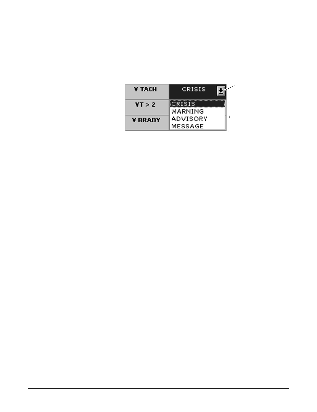
Parameter Alarm Levels . . . . . . . . . . . . . . . . . . . . . . . . . . . . . . . . . . . . . . . . . . . .8-7
Arrhythmia Alarm Levels . . . . . . . . . . . . . . . . . . . . . . . . . . . . . . . . . . . . . . . . . . . . 8-8
Alarms On/Off . . . . . . . . . . . . . . . . . . . . . . . . . . . . . . . . . . . . . . . . . . . . . . . . . . . . 8-9
Recalling Unit Defaults . . . . . . . . . . . . . . . . . . . . . . . . . . . . . . . . . . . . . . . . . . . . . 8-12
Alarm Help . . . . . . . . . . . . . . . . . . . . . . . . . . . . . . . . . . . . . . . . . . . . . . . . . . . . . . 8-12
Printing Alarm Settings . . . . . . . . . . . . . . . . . . . . . . . . . . . . . . . . . . . . . . . . . . . .8-13
Silencing Alarms . . . . . . . . . . . . . . . . . . . . . . . . . . . . . . . . . . . . . . . . . . . . . . . . . 8-13
Alarm Pause Breakthrough . . . . . . . . . . . . . . . . . . . . . . . . . . . . . . . . . . . . . . . . . . 8-14
Unit Default Settings for Alarms . . . . . . . . . . . . . . . . . . . . . . . . . . . . . . . . . . . . . . 8-16
Telemetry Alarm Control Defaults . . . . . . . . . . . . . . . . . . . . . . . . . . . . . . . . . . . . 8-16
iv ApexPro Telemetry System Revision D
2001989-134

9 Printing . . . . . . . . . . . . . . . . . . . . . . . . . . . . . . . . . . . . . . . . 9-1
Initiating a Manual Graph . . . . . . . . . . . . . . . . . . . . . . . . . . . . . . . . . . . . . . . . . . . . . 9-3
Automatic Alarm Graphs . . . . . . . . . . . . . . . . . . . . . . . . . . . . . . . . . . . . . . . . . . . . 9-3
Transmitter Initiated Graphs (Manual Graphs) . . . . . . . . . . . . . . . . . . . . . . . . . . .9-4
Graph Messages . . . . . . . . . . . . . . . . . . . . . . . . . . . . . . . . . . . . . . . . . . . . . . . . . . 9-5
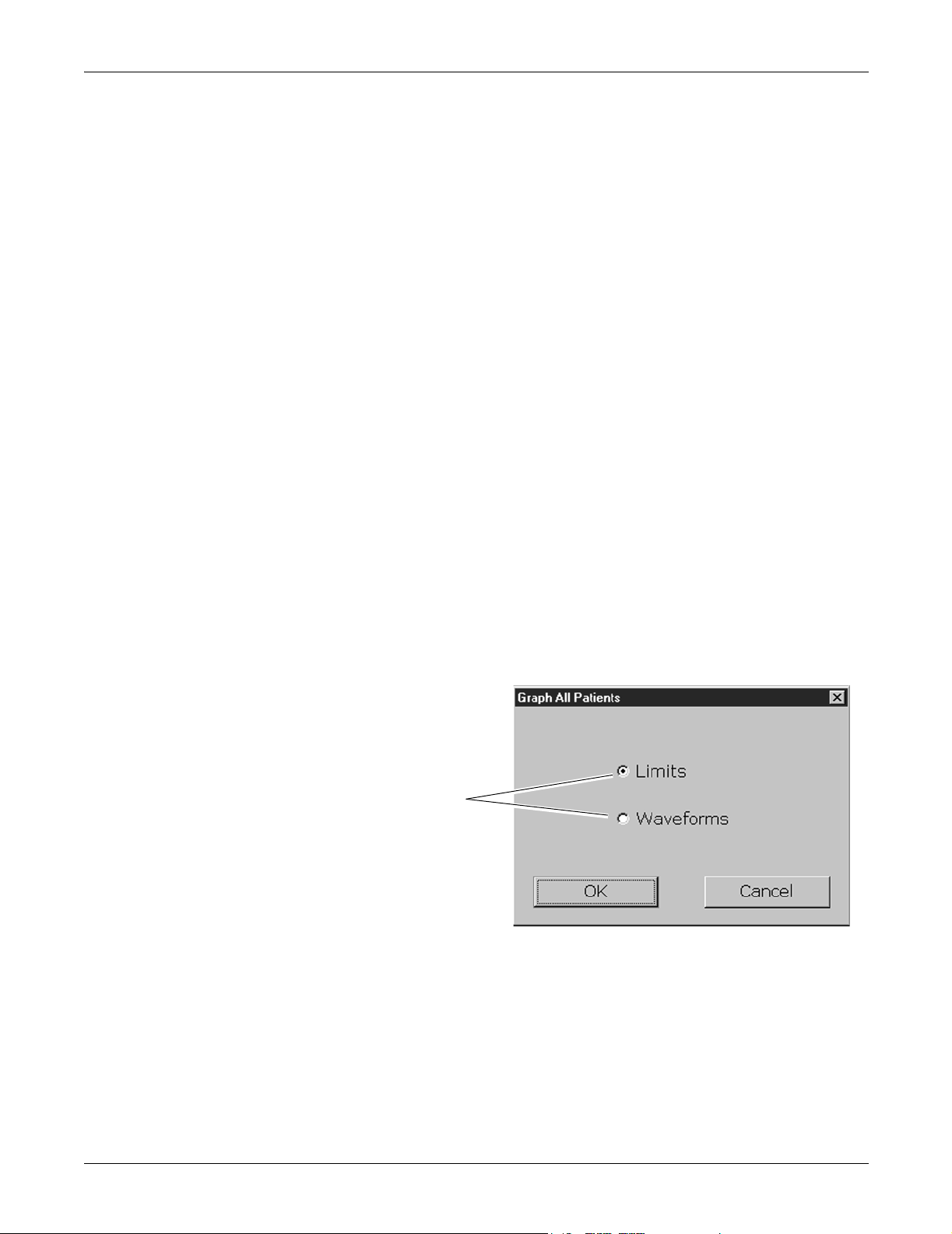
Graph All Patients . . . . . . . . . . . . . . . . . . . . . . . . . . . . . . . . . . . . . . . . . . . . . . . . . . . 9-6
Initiating a Graph All Patients Request . . . . . . . . . . . . . . . . . . . . . . . . . . . . . . . . . 9-7
Graph Location Settings . . . . . . . . . . . . . . . . . . . . . . . . . . . . . . . . . . . . . . . . . . . . . . 9-8
Stopping a Graph . . . . . . . . . . . . . . . . . . . . . . . . . . . . . . . . . . . . . . . . . . . . . . . . . . . . 9-9
Graph Paper Out Indicator . . . . . . . . . . . . . . . . . . . . . . . . . . . . . . . . . . . . . . . . . . . 9-10
Graph Setup Tab Sheet . . . . . . . . . . . . . . . . . . . . . . . . . . . . . . . . . . . . . . . . . . . . . . 9-11
Graph Waveforms Controls . . . . . . . . . . . . . . . . . . . . . . . . . . . . . . . . . . . . . . . . .9-12
Graph Location Controls . . . . . . . . . . . . . . . . . . . . . . . . . . . . . . . . . . . . . . . . . . . 9-13
Graph Speed Controls . . . . . . . . . . . . . . . . . . . . . . . . . . . . . . . . . . . . . . . . . . . . . 9-15
Laser Printer . . . . . . . . . . . . . . . . . . . . . . . . . . . . . . . . . . . . . . . . . . . . . . . . . . . . . . . 9-16
10 Patient Data . . . . . . . . . . . . . . . . . . . . . . . . . . . . . . . . . . . 10-1
Introduction . . . . . . . . . . . . . . . . . . . . . . . . . . . . . . . . . . . . . . . . . . . . . . . . . . . . . . . 10-3
Alarm Histories . . . . . . . . . . . . . . . . . . . . . . . . . . . . . . . . . . . . . . . . . . . . . . . . . . . . 10-4
Event Directory . . . . . . . . . . . . . . . . . . . . . . . . . . . . . . . . . . . . . . . . . . . . . . . . . .10-5
Event Window . . . . . . . . . . . . . . . . . . . . . . . . . . . . . . . . . . . . . . . . . . . . . . . . . . . 10-5
Alarm Histories Buttons . . . . . . . . . . . . . . . . . . . . . . . . . . . . . . . . . . . . . . . . . . . .10-6
Graphic Trends . . . . . . . . . . . . . . . . . . . . . . . . . . . . . . . . . . . . . . . . . . . . . . . . . . . . 10-8
Trend Directory Window . . . . . . . . . . . . . . . . . . . . . . . . . . . . . . . . . . . . . . . . . . .10-8
Cursor . . . . . . . . . . . . . . . . . . . . . . . . . . . . . . . . . . . . . . . . . . . . . . . . . . . . . . . . . 10-9
Time Resolution Menu . . . . . . . . . . . . . . . . . . . . . . . . . . . . . . . . . . . . . . . . . . . . 10-10
Graphic Trends Buttons . . . . . . . . . . . . . . . . . . . . . . . . . . . . . . . . . . . . . . . . . . . 10-10
Printing Graphic Trends . . . . . . . . . . . . . . . . . . . . . . . . . . . . . . . . . . . . . . . . . . . 10-12
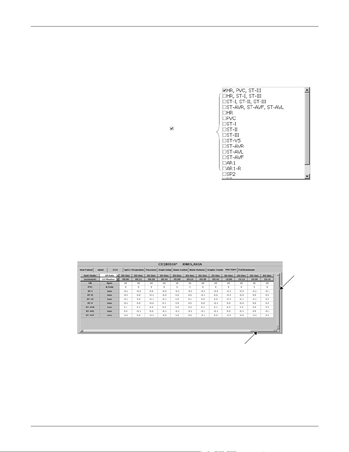
Vital Signs . . . . . . . . . . . . . . . . . . . . . . . . . . . . . . . . . . . . . . . . . . . . . . . . . . . . . . . 10-13
Data Source . . . . . . . . . . . . . . . . . . . . . . . . . . . . . . . . . . . . . . . . . . . . . . . . . . . . 10-13
Sort Mode . . . . . . . . . . . . . . . . . . . . . . . . . . . . . . . . . . . . . . . . . . . . . . . . . . . . .10-14
Increment . . . . . . . . . . . . . . . . . . . . . . . . . . . . . . . . . . . . . . . . . . . . . . . . . . . . . . 10-14
Scroll Bars . . . . . . . . . . . . . . . . . . . . . . . . . . . . . . . . . . . . . . . . . . . . . . . . . . . . . 10-15
Printing Vital Signs . . . . . . . . . . . . . . . . . . . . . . . . . . . . . . . . . . . . . . . . . . . . . . . 10-15
Data Source . . . . . . . . . . . . . . . . . . . . . . . . . . . . . . . . . . . . . . . . . . . . . . . . . . . . . . 10-16
Revision D ApexPro Telemetry System v
2001989-134

Time Focus . . . . . . . . . . . . . . . . . . . . . . . . . . . . . . . . . . . . . . . . . . . . . . . . . . . . . . . 10-17
Full Disclosure . . . . . . . . . . . . . . . . . . . . . . . . . . . . . . . . . . . . . . . . . . . . . . . . . . . . 10-18
Full Disclosure Options . . . . . . . . . . . . . . . . . . . . . . . . . . . . . . . . . . . . . . . . . . . 10-19
11 ECG Monitoring . . . . . . . . . . . . . . . . . . . . . . . . . . . . . . . . 11-1
Introduction . . . . . . . . . . . . . . . . . . . . . . . . . . . . . . . . . . . . . . . . . . . . . . . . . . . . . . . 11-3
Data Synchronization . . . . . . . . . . . . . . . . . . . . . . . . . . . . . . . . . . . . . . . . . . . . . . 11-3
Patient Preparation . . . . . . . . . . . . . . . . . . . . . . . . . . . . . . . . . . . . . . . . . . . . . . . . . 11-4
Skin Preparation . . . . . . . . . . . . . . . . . . . . . . . . . . . . . . . . . . . . . . . . . . . . . . . . .11-4
Electrode Placement . . . . . . . . . . . . . . . . . . . . . . . . . . . . . . . . . . . . . . . . . . . . . . 11-4
Special Considerations for 6-Lead Monitoring . . . . . . . . . . . . . . . . . . . . . . . . . . 11-10
V FAIL Message . . . . . . . . . . . . . . . . . . . . . . . . . . . . . . . . . . . . . . . . . . . . . . . .11-10
Relearn . . . . . . . . . . . . . . . . . . . . . . . . . . . . . . . . . . . . . . . . . . . . . . . . . . . . . . .11-10
ECG Monitoring . . . . . . . . . . . . . . . . . . . . . . . . . . . . . . . . . . . . . . . . . . . . . . . . . . . 11-11
ECG in the Multiple Patient Viewer . . . . . . . . . . . . . . . . . . . . . . . . . . . . . . . . . . 11-11
ECG in the Single Patient Viewer . . . . . . . . . . . . . . . . . . . . . . . . . . . . . . . . . . . 11-12
ECG Limits . . . . . . . . . . . . . . . . . . . . . . . . . . . . . . . . . . . . . . . . . . . . . . . . . . . . . 11-13
ECG Artifact . . . . . . . . . . . . . . . . . . . . . . . . . . . . . . . . . . . . . . . . . . . . . . . . . . . . 11-14
ECG Tab Sheet . . . . . . . . . . . . . . . . . . . . . . . . . . . . . . . . . . . . . . . . . . . . . . . . . . . . 11-15
Accessing the ECG Tab Sheet . . . . . . . . . . . . . . . . . . . . . . . . . . . . . . . . . . . . . 11-15
Display Lead . . . . . . . . . . . . . . . . . . . . . . . . . . . . . . . . . . . . . . . . . . . . . . . . . . . 11-16
Relearn . . . . . . . . . . . . . . . . . . . . . . . . . . . . . . . . . . . . . . . . . . . . . . . . . . . . . . .11-16
Size . . . . . . . . . . . . . . . . . . . . . . . . . . . . . . . . . . . . . . . . . . . . . . . . . . . . . . . . . . 11-16
Detect Pace . . . . . . . . . . . . . . . . . . . . . . . . . . . . . . . . . . . . . . . . . . . . . . . . . . . .11-17
Lead Analysis . . . . . . . . . . . . . . . . . . . . . . . . . . . . . . . . . . . . . . . . . . . . . . . . . . . 11-22
Arrhythmia . . . . . . . . . . . . . . . . . . . . . . . . . . . . . . . . . . . . . . . . . . . . . . . . . . . . . 11-24
Full Arrhythmia Conditions . . . . . . . . . . . . . . . . . . . . . . . . . . . . . . . . . . . . . . . . . 11-26
Lethal Arrhythmia Conditions . . . . . . . . . . . . . . . . . . . . . . . . . . . . . . . . . . . . . . . 11-29
PVC Limit . . . . . . . . . . . . . . . . . . . . . . . . . . . . . . . . . . . . . . . . . . . . . . . . . . . . . . 11-29
ST . . . . . . . . . . . . . . . . . . . . . . . . . . . . . . . . . . . . . . . . . . . . . . . . . . . . . . . . . . .11-29
Va Lead and Vb Lead . . . . . . . . . . . . . . . . . . . . . . . . . . . . . . . . . . . . . . . . . . . . 11-29
AFIB Identification . . . . . . . . . . . . . . . . . . . . . . . . . . . . . . . . . . . . . . . . . . . . . . . 11-30
ST Analysis . . . . . . . . . . . . . . . . . . . . . . . . . . . . . . . . . . . . . . . . . . . . . . . . . . . . . . 11-31
ST Deviation Alarm . . . . . . . . . . . . . . . . . . . . . . . . . . . . . . . . . . . . . . . . . . . . . . 11-32
Arrhythmia Troubleshooting . . . . . . . . . . . . . . . . . . . . . . . . . . . . . . . . . . . . . . . . 11-33
Pacemaker Troubleshooting . . . . . . . . . . . . . . . . . . . . . . . . . . . . . . . . . . . . . . . . 11-35
Interface Connector Ports . . . . . . . . . . . . . . . . . . . . . . . . . . . . . . . . . . . . . . . . . 11-35
ST Troubleshooting . . . . . . . . . . . . . . . . . . . . . . . . . . . . . . . . . . . . . . . . . . . . . . . . 11-37
vi ApexPro Telemetry System Revision D
2001989-134

12 SpO2 Monitoring . . . . . . . . . . . . . . . . . . . . . . . . . . . . . . . 12-1
Introduction . . . . . . . . . . . . . . . . . . . . . . . . . . . . . . . . . . . . . . . . . . . . . . . . . . . . . . . 12-3
SpO2 Probe Safety . . . . . . . . . . . . . . . . . . . . . . . . . . . . . . . . . . . . . . . . . . . . . . . 12-4
Infants and Pulse Oximetry . . . . . . . . . . . . . . . . . . . . . . . . . . . . . . . . . . . . . . . . . . . 12-5
Signal and Data Validity . . . . . . . . . . . . . . . . . . . . . . . . . . . . . . . . . . . . . . . . . . . . . 12-6
Signal Strength Indicator . . . . . . . . . . . . . . . . . . . . . . . . . . . . . . . . . . . . . . . . . . . 12-6
Error Messages . . . . . . . . . . . . . . . . . . . . . . . . . . . . . . . . . . . . . . . . . . . . . . . . . . 12-7
SPO2 Monitoring . . . . . . . . . . . . . . . . . . . . . . . . . . . . . . . . . . . . . . . . . . . . . . . . . . . 12-8
SPO2 in the Multiple Patient Viewer . . . . . . . . . . . . . . . . . . . . . . . . . . . . . . . . . . 12-8
SPO2 in the Single Patient Viewer . . . . . . . . . . . . . . . . . . . . . . . . . . . . . . . . . . .12-9
SPO2 Limits . . . . . . . . . . . . . . . . . . . . . . . . . . . . . . . . . . . . . . . . . . . . . . . . . . . . . 12-9
SPO2 Tab Sheet . . . . . . . . . . . . . . . . . . . . . . . . . . . . . . . . . . . . . . . . . . . . . . . . . . . 12-10
Accessing the SPO2 Tab Sheet . . . . . . . . . . . . . . . . . . . . . . . . . . . . . . . . . . . .12-10
Rate . . . . . . . . . . . . . . . . . . . . . . . . . . . . . . . . . . . . . . . . . . . . . . . . . . . . . . . . . .12-11
Size . . . . . . . . . . . . . . . . . . . . . . . . . . . . . . . . . . . . . . . . . . . . . . . . . . . . . . . . . . 12-11
Troubleshooting . . . . . . . . . . . . . . . . . . . . . . . . . . . . . . . . . . . . . . . . . . . . . . . . . . . 12-12
SpO2 Messages . . . . . . . . . . . . . . . . . . . . . . . . . . . . . . . . . . . . . . . . . . . . . . . .12-12
13 NBP Monitoring . . . . . . . . . . . . . . . . . . . . . . . . . . . . . . . . 13-1
Introduction . . . . . . . . . . . . . . . . . . . . . . . . . . . . . . . . . . . . . . . . . . . . . . . . . . . . . . . 13-3
Safety Considerations . . . . . . . . . . . . . . . . . . . . . . . . . . . . . . . . . . . . . . . . . . . . . . . 13-4
Programming the Blood Pressure Monitor . . . . . . . . . . . . . . . . . . . . . . . . . . . . . . 13-5
Setting the Measurement Interval . . . . . . . . . . . . . . . . . . . . . . . . . . . . . . . . . . . . 13-5
Setting Test Parameters . . . . . . . . . . . . . . . . . . . . . . . . . . . . . . . . . . . . . . . . . . . 13-6
Setting Limits . . . . . . . . . . . . . . . . . . . . . . . . . . . . . . . . . . . . . . . . . . . . . . . . . . . .13-8
Software and Hardware Versions . . . . . . . . . . . . . . . . . . . . . . . . . . . . . . . . . . . . 13-8
Patient Preparation . . . . . . . . . . . . . . . . . . . . . . . . . . . . . . . . . . . . . . . . . . . . . . . . . 13-9
Microphone Placement . . . . . . . . . . . . . . . . . . . . . . . . . . . . . . . . . . . . . . . . . . . 13-11
NBP Monitoring . . . . . . . . . . . . . . . . . . . . . . . . . . . . . . . . . . . . . . . . . . . . . . . . . . . 13-13
NBP in the Multiple Patient Viewer . . . . . . . . . . . . . . . . . . . . . . . . . . . . . . . . . . 13-13
NBP in the Single Patient Viewer . . . . . . . . . . . . . . . . . . . . . . . . . . . . . . . . . . . . 13-13
NBP Limits . . . . . . . . . . . . . . . . . . . . . . . . . . . . . . . . . . . . . . . . . . . . . . . . . . . . . 13-14
Revision D ApexPro Telemetry System vii
2001989-134

Pressures Tab Sheet . . . . . . . . . . . . . . . . . . . . . . . . . . . . . . . . . . . . . . . . . . . . . . . 13-15
Accessing the Pressures Tab Sheet . . . . . . . . . . . . . . . . . . . . . . . . . . . . . . . . . 13-15
Auto . . . . . . . . . . . . . . . . . . . . . . . . . . . . . . . . . . . . . . . . . . . . . . . . . . . . . . . . . . 13-16
Cuff Size . . . . . . . . . . . . . . . . . . . . . . . . . . . . . . . . . . . . . . . . . . . . . . . . . . . . . .13-16
Clear Message . . . . . . . . . . . . . . . . . . . . . . . . . . . . . . . . . . . . . . . . . . . . . . . . . . 13-16
Troubleshooting . . . . . . . . . . . . . . . . . . . . . . . . . . . . . . . . . . . . . . . . . . . . . . . . . . 13-17
NBP Status Messages . . . . . . . . . . . . . . . . . . . . . . . . . . . . . . . . . . . . . . . . . . . . 13-17
Message Glossary . . . . . . . . . . . . . . . . . . . . . . . . . . . . . . . .A-1
Message Glossary . . . . . . . . . . . . . . . . . . . . . . . . . . . . . . . . . . . . . . . . . . . . . . . . . . . A-3
Alarm Messages . . . . . . . . . . . . . . . . . . . . . . . . . . . . . . . . . . . . . . . . . . . . . . . . . .A-3
Graph Messages . . . . . . . . . . . . . . . . . . . . . . . . . . . . . . . . . . . . . . . . . . . . . . . . . .A-5
Transmitter-Related Messages . . . . . . . . . . . . . . . . . . . . . . . . . . . . . . . . . . . . . . .A-6
System Status Messages . . . . . . . . . . . . . . . . . . . . . . . . . . . . . . . . . . . . . . . . . . .A-6
Patient Status Messages . . . . . . . . . . . . . . . . . . . . . . . . . . . . . . . . . . . . . . . . . . . .A-7
Supplies . . . . . . . . . . . . . . . . . . . . . . . . . . . . . . . . . . . . . . . .B-1
Contact Information . . . . . . . . . . . . . . . . . . . . . . . . . . . . . . . . . . . . . . . . . . . . . . . . . . B-3
Abbreviations and Symbols . . . . . . . . . . . . . . . . . . . . . . . .C-1
Abbreviations and Symbols . . . . . . . . . . . . . . . . . . . . . . . . . . . . . . . . . . . . . . . . . . . C-3
Abbreviations . . . . . . . . . . . . . . . . . . . . . . . . . . . . . . . . . . . . . . . . . . . . . . . . . . . . .C-3
Symbols . . . . . . . . . . . . . . . . . . . . . . . . . . . . . . . . . . . . . . . . . . . . . . . . . . . . . . . . .C-7
viii ApexPro Telemetry System Revision D
2001989-134

ApexPro FH Transceiver . . . . . . . . . . . . . . . . . . . . . . . . . .D-1
The Basics . . . . . . . . . . . . . . . . . . . . . . . . . . . . . . . . . . . . . . . . . . . . . . . . . . . . . . . . . D-3
About the ApexPro FH Transceiver . . . . . . . . . . . . . . . . . . . . . . . . . . . . . . . . . . . .D-3
Programming Transceivers . . . . . . . . . . . . . . . . . . . . . . . . . . . . . . . . . . . . . . . . . .D-4
Safety . . . . . . . . . . . . . . . . . . . . . . . . . . . . . . . . . . . . . . . . . . . . . . . . . . . . . . . . . . . . . D-5
Warnings, Cautions, and Notes . . . . . . . . . . . . . . . . . . . . . . . . . . . . . . . . . . . . . . .D-5
Equipment Overview . . . . . . . . . . . . . . . . . . . . . . . . . . . . . . . . . . . . . . . . . . . . . . . . . D-8
ApexPro FH Transceiver Operating Instructions . . . . . . . . . . . . . . . . . . . . . . . . . .D-8
Push Button Function and Use . . . . . . . . . . . . . . . . . . . . . . . . . . . . . . . . . . . . . . .D-8
Attendant Present/Procedure Alarm Silence (PAS) Unlock Button . . . . . . . . . . . .D-9
Procedure Alarm Silence (PAS) Button . . . . . . . . . . . . . . . . . . . . . . . . . . . . . . . .D-10
LED Indicators Function . . . . . . . . . . . . . . . . . . . . . . . . . . . . . . . . . . . . . . . . . . . .D-12
Connections . . . . . . . . . . . . . . . . . . . . . . . . . . . . . . . . . . . . . . . . . . . . . . . . . . . . . . . D-14
Connecting the ApexPro FH Transceiver to Accessory Devices . . . . . . . . . . . . .D-14
Maintenance . . . . . . . . . . . . . . . . . . . . . . . . . . . . . . . . . . . . . . . . . . . . . . . . . . . . . . . D-18
General Cleaning/Disinfecting . . . . . . . . . . . . . . . . . . . . . . . . . . . . . . . . . . . . . . .D-18
Storage and Usage . . . . . . . . . . . . . . . . . . . . . . . . . . . . . . . . . . . . . . . . . . . . . . .D-23
Compliance . . . . . . . . . . . . . . . . . . . . . . . . . . . . . . . . . . . . . . . . . . . . . . . . . . . . . . . D-26
Compliance Statement . . . . . . . . . . . . . . . . . . . . . . . . . . . . . . . . . . . . . . . . . . . . .D-26
Index . . . . . . . . . . . . . . . . . . . . . . . . . . . . . . . . . . . . . . . Index-1
Revision D ApexPro Telemetry System ix
2001989-134

For your notes
x ApexPro Telemetry System Revision D
2001989-134

1 The Basics
Revision D ApexPro Telemetry System 1-1
2001989-134

For your notes
1-2 ApexPro Telemetry System Revision D
2001989-134

About This Manual
Manual Purpose
This manual contains the instructions necessary to operate the ApexPro
telemetry system safely and in accordance with its function and intended
use.
This manual addresses the operation of the ApexPro telemetry system at
the CIC Pro. Be sure to read the entire manual before using the
equipment.
Intended Audience
This manual is geared for clinical professionals. Clinical professionals
are expected to have a working knowledge of medical procedures,
practices, and terminology, as required for monitoring of critically ill
patients.
The Basics: About This Manual
This manual assumes that you are familiar with the operating
procedures of the CIC Pro. If you would like more information about
using the CIC Pro, refer to the CIC Pro Clinical Information Center
Operator’s Manual.
This manual also assumes that you are familiar with the operation of a
two-button computer mouse. If you would like more information about
operating the mouse, refer to the CIC Pro Clinical Information Center
Operator’s Manual, or to the documentation supplied with the mouse.
Revision D ApexPro Telemetry System 1-3
2001989-134

Revision History
The Basics: About This Manual
Each page of the document has the document part number and revision
letter at the bottom of the page. The revision letter changes whenever
the document is updated.
Revision Date Comments
A 25 June 2003 Initial release of this document, corresponding to
ApexPro telemetry system software version 3.
B 23 October 2003
C 21 January 2004
D 12 March 2004
Updated to support the ApexPro FH Transceiver
Added additional CE Exceptions for the ApexPro
system.
Added FCC Compliance
Added Industry Canada Compliance
Changed Nurse Graph to Event Marker Graph and
Transmitter Nurse to Event Marker
Added Data Source information
Changed recommended cleaning solutions
Added information regarding time discrepancy
between waveforms
Added information on stopping manual graphs
Made correction to INTFC connector ports 1 and 2
Updated Equipment Symbols
Warning added regarding adjusting System Status
Alarms levels
Added verify lead information to the admit procedure
and electrode placement
Message alarm level added to System Status Alarm
Graph Location Settings information revised
Removed reference to alarm level settings for ARR
SUSPEND, LEADS FAIL, and OFF NETWORK
Changes made to Appendix D for the ApexPro FH
Transceiver
1-4 ApexPro Telemetry System Revision D
2001989-134

Manual Conventions
This section describes terminology, standards, and other conventions
that are used throughout this manual.
Product References
In this manual:
The ApexPro telemetry system is referred to as the ApexPro system,
or simply the system.
The CIC Pro Clinical Information Center is referred to as the clinical
information center, the CIC Pro or the central station.
The SunTech Medical Systems Accutracker DX noninvasive blood
pressure monitor is referred to as the blood pressure monitor or the
Accutracker.
The PRN 50 Digital Writer is referred to as the digital writer or the
writer.
The Direct Digital Writers are referred to as DDWs or writers.
The laser printer is referred to as the printer.
The Basics: Manual Conventions
Definitions
The following terms are used in this manual:
Buttons — The word “button” is defined in two ways:
1. A button is a labeled gray or red rectangle on the CIC Pro. Clicking
on a button with the mouse pointer opens a tab sheet or performs the
specified action (such as Print). Red buttons are used to view beds in
alarm.
2. A button is a labeled circle, square, or rectangle located on the
ApexPro transmitter, the Apex Oximeter, or the Accutracker blood
pressure monitor. Pressing the button with your finger activates it.
NOTE
The computer mouse used with the CIC Pro also has two buttons.
Refer to the CIC Pro Clinical Information Center Operator’s Manual
for information about using those buttons.
Revision D ApexPro Telemetry System 1-5
2001989-134

The Basics: Manual Conventions
Messages/Prompts — A message is text that appears on the CIC Pro. It
informs you of conditions occurring that are not necessarily part of
normal operating conditions. Prompts are text messages that appear,
instructing you to perform a specific action.
Multiple patient viewer — The multiple patient viewer is the CIC Pro
display in its normal state. Bed windows for admitted patients are
shown, as well as a menu bar at the bottom of the display.
Screen text — Any text that appears on the CIC Pro display. In this
manual, screen text is shown in italics (for example, ECG, SAVING, etc.).
Single patient viewer — When you click on a patient’s bed window at
the CIC Pro, the display rearranges to accommodate a set of tab sheets
(see definition below) in the bottom portion of the display. This set of tab
sheets is referred to as the single patient viewer because it contains
information specific to one patient.
Tab options — Tab options are the choices and text entry fields
available on a tab sheet. The information presented as tab options may
pertain to a patient’s data, or may be control information (such as alarm
settings) that can be modified to meet the user’s specific needs.
Tab sheets — Tab sheets look like labeled index cards. The menu tab
labels indicate the type of information to be viewed and/or changed on its
tab sheet. Clicking on a tab brings its tab sheet to the front of the “index
card” stack, or to the front of the currently viewed window.
Tabs — Tabs are the labeled section of the tab sheets. Clicking on a tab
brings its tab sheet to the front. Tab and tab sheet are sometimes used
interchangeably.
Illustrations and Names
All illustrations in this manual are provided as examples only. They may
not necessarily reflect your telemetry monitoring setup or data displayed
on your equipment.
In this manual, all names appearing in examples and illustrations are
fictitious. The use of any real person’s name is purely coincidental.
1-6 ApexPro Telemetry System Revision D
2001989-134
Common Operations
Some operations are used repetitively at the CIC Pro or the ApexPro
telemetry system. Rather than explaining how to perform each operation
every time it appears in this manual, these operations are presented
below. Please familiarize yourself with the proper procedure for each.
“Clicking” the Mouse
The term “click” refers to positioning the mouse pointer on a selection
and pressing the left mouse button one time.
In situations where the right mouse button should be pressed, this is
specifically called out. In all other cases, assume that you should press
the LEFT mouse button.
Pressing the mouse button two times in a row is called double clicking. In
situations where the mouse needs to be double clicked to perform a
function, this is specifically called out. In all other cases, assume that you
only need to click the mouse button ONE time.
The Basics: Common Operations
Radio Buttons
To use a radio button control, click on the white circle (radio button) or
the text next to it. When selected, a black dot is shown in the white circle.
To deselect a radio button control, click again on the label text or in the
white circle. When it is not selected, no black dot is shown.
Radio Buttons —
“Dot” in center
indicates active
selection.
007A
Revision D ApexPro Telemetry System 1-7
2001989-134
Check Boxes
The Basics: Common Operations
To use check box controls, click on the square or the text next to it. When
selected, a check mark is shown in this square. To deselect a check box
control, click again on the text or in the square. When deselected, no
check mark is shown.
Check Boxes —
indicates active
selection.
078B
Scroll Bars
Use horizontal and vertical scroll bars to move a window’s contents left/
right and up/down. Place the mouse pointer on the appropriate arrow to
move the scroll bar, or click and hold the mouse button down while
dragging the scroll bar until the desired information is displayed.
Vertical
Scroll
Bar
Horizontal
Scroll Bar
359A
1-8 ApexPro Telemetry System Revision D
2001989-134
Popup Lists
The Basics: Common Operations
Clicking in a text field may produce a down arrow button on the right
side of the field. This arrow button is used to open a popup list. A popup
list is a list of options available for that particular field. Use the mouse to
click on the arrow button, which opens the popup list.
Arrow Button —
indicates there is a
popup list.
Popup List
332A
Once the popup list is open, use the mouse to click on an option. This
selects the option and closes the popup list.
NOTE
If you click on the right side of a field, the down arrow button and the
popup list of selections may appear simultaneously.
Revision D ApexPro Telemetry System 1-9
2001989-134

The Basics: Unit Defaults Worksheet
Unit Defaults Worksheet
This worksheet has been provided as an optional reference tool to record
your care unit’s default settings. Fill out the information and keep it in a
prominent place to refer to your setup. For your convenience, the factory
default settings appears dimmed. Fill in only those settings that differ
from the factory default ones.
NOTE
Before you fill it out, you may want to make additional copies of the
worksheet for future use.
Date: Unit:
Telemetry Alarm Control Defaults
Parameter Limits and Alarm Levels Low High Level Arrhythmia Alarm Levels Levels
HR bpm 50 150 Warning Asystole Crisis
ST-I mm -2.0 2.0 Warning VFIB/VTAC Crisis
ST-II mm -2.0 2.0 Warning V Tach Crisis
ST-III mm -2.0 2.0 Warning VT > 2 Crisis
ST-V mm -2.0 2.0 Warning V Brady Crisis
ST-V2 mm -2.0 2.0 Warning Acc Vent Advisory
ST-V3 mm -2.0 2.0 Warning Pause Advisory
ST-V4 mm -2.0 2.0 Warning Tachy Advisory
ST-V5 mm -2.0 2.0 Warning Brady Advisory
ST-V6 mm -2.0 2.0 Warning R on T Message
ST-AVR mm -2.0 2.0 Warning Couplet Message
ST-AVL mm -2.0 2.0 Warning Bigeminy Message
ST-AVF mm -2.0 2.0 Warning Trigeminy Message
NBP-S mmHg 80 200 Warning PVC Message
NBP-D mmHg 20 120 Warning Irregular Message
NBP-M mmHg 40 140 Warning Atrial Fib Message
SPO2 % 90 105 Warning
SPO2-R bpm 50 150 Warning System Alarm Levels Levels
RR breaths/min 5 30 Warning Change Battery Sys Warning
RR-APNEA seconds 30 Warning Off Network Sys Warning
PVC #/min 6 Advisory Arr Suspend Sys Warning
Leads Fail Sys Warning
Probe Off Sys Warning
1-10 ApexPro Telemetry System Revision D
2001989-134

The Basics: Unit Defaults Worksheet
Telemetry Unit Defaults
Graph Setup: ECG:
Manual Graph Location Display Lead
Alarm Graph Location Arrhythmia
Print Window Graph Location Lead Analysis
ST Analysis
Va Lead
Waveforms: Vb Lead
ECG 1 Waveform Display Detect Pace
Waveform 2 Display
Waveform 3 Display
Waveform 4 Display Patient Age
Transmitter Alarm Pause
Alarm Pause Breakthrough
Transmitter Graph Event Marker*
Alarm Graph On/Off
Event Marker Graph On/Off*
*The Event Marker Graph and Event Marker features are not applicable
to all transmitters.
Revision D ApexPro Telemetry System 1-11
2001989-134

For your notes
The Basics: Unit Defaults Worksheet
1-12 ApexPro Telemetry System Revision D
2001989-134

2 Safety
Revision D ApexPro Telemetry System 2-1
2001989-134

For your notes
2-2 ApexPro Telemetry System Revision D
2001989-134

For Your Safety
Intended Use
Safety: For Your Safety
The ApexPro Telemetry System is intended for use under the direct
supervision of a licensed healthcare practitioner. The system is designed
to acquire and monitor physiological data for ambulating patients within
a defined coverage area. The system processes this physiological data to
detect various ECG arrhythmia events and select physiological
parameter limit violations.
The ApexPro Telemetry System is intended to be installed in the hospital
or clinical environment in order to provide clinicians with patient
physiological data, while allowing for patient mobility. These systems
are typically deployed in sub acute care areas in hospitals or clinical sites
where patient mobility can enhance the effectiveness of the medical
procedures administered.
The physiological parameters monitored include ECG, non-invasive
blood pressure and SpO2. The ApexPro Telemetry System is intended to
provide ECG data via Ethernet to the computer platform for processing.
The ApexPro is also intended to provide physiologic data over the Unity
network to clinical information systems for display.
Definitions
The terms danger, warning, and caution are used throughout this
manual to point out hazards and to designate a degree or level or
seriousness. Familiarize yourself with their definitions and significance.
Hazard is defined as a source of potential injury to a person.
DANGER indicates an imminent hazard which, if not avoided, will
result in death or serious injury.
WARNING indicates a potential hazard or unsafe practice which, if not
avoided, could result in death or serious injury.
CAUTION indicates a potential hazard or unsafe practice which, if not
avoided, could result in minor personal injury or product/property
damage.
NOTE provides application tips or other useful information to assure
that you get the most from your equipment.
Revision D ApexPro Telemetry System 2-3
2001989-134

System Safety
Dangers
Warnings
Safety: For Your Safety
The safety statements presented in this chapter refer to the equipment
in general and, in most cases, apply to all aspects of the telemetry
system. There are additional safety statements in other chapters that are
specific to the information presented in that chapter.
The order in which safety statements are presented in no way implies
order of importance.
There are no dangers that refer to the equipment in general. Specific
“Danger” statements may be given in the respective sections of this
manual.
WARNINGS
ACCIDENTAL SPILLS — To avoid electric shock or
device malfunction liquids must not be allowed to enter
the device. If liquids have entered a device, take it out of
service and have it checked by a service technician before
it is used again.
ACCURACY — If the accuracy of any value displayed on
the monitor, central station, or printed on a graph strip is
questionable, determine the patient's vital signs by
alternative means. Verify that all equipment is working
correctly.
ADJUSTING SYSTEM ALARM LEVELS — The LEADS
FAIL alarm indicates that one or more electrodes are not
connected to the patient and, as a result, there is loss of
all waveforms and arrhythmia analysis. The ARR
SUSPEND alarm indicates that arrhythmia conditions
are not being detected and therefore alarms associated
with arrhythmias will not occur. The LEADS FAIL and
ARR SUSPEND alarms should be adjusted to a lower
priority level only by experienced qualified personnel and
with great caution. Adjusting these alarms to a lower
priority level may result in reduced awareness of
conditions that indicate the loss of patient monitoring.
2-4 ApexPro Telemetry System Revision D
2001989-134

Safety: For Your Safety
WARNINGS
ALARMS — Do not rely exclusively on the audible alarm
system for patient monitoring. Adjustment of alarm
volume to a low level or off during patient monitoring
may result in a hazard to the patient.
Do not rely exclusively on the alarm pause breakthrough
feature for alarm notification during an alarm pause.
This may result in a hazard to the patient. Only crisis
alarms break through an alarm pause.
Remember that the most reliable method of patient
monitoring combines close personal surveillance with
correct operation of monitoring equipment.
After connecting the monitor to the central station, nurse
alert system, and/or network, verify the function of the
alarm system.
The functions of the alarm system for monitoring of the
patient must be verified at regular intervals.
BEFORE USE — Before putting the system into
operation visually inspect all connecting cables for signs
of damage. Damaged cables and connectors must be
replaced immediately.
Before using the system, the operator must verify that it
is in correct working order and operating condition.
Periodically, and whenever the integrity of the product is
in doubt, test all functions.
CABLES — Route all cables away from patient's throat
to avoid possible strangulation.
Revision D ApexPro Telemetry System 2-5
2001989-134

Safety: For Your Safety
WARNINGS
CONDUCTIVE CONNECTIONS — Extreme care must
be exercised when applying medical electrical equipment.
Many parts of the human/machine circuit are conductive,
such as the patient, connectors, electrodes, transducers.
It is very important that these conductive parts do not
come into contact with other grounded, conductive parts
when connected to the isolated patient input of the
device. Such contact would bridge the patient's isolation
and cancel the protection provided by the isolated input.
In particular, there must be no contact of the neutral
electrode and ground.
DEFIBRILLATION — Do not come into contact with
patients during defibrillation. Otherwise serious injury
or death could result.
DISCONNECTION FROM MAINS — When
disconnecting the system from the power line, remove the
plug from the wall outlet first. Then you may disconnect
the power cord from the device. If you do not observe this
sequence, there is a risk of coming into contact with line
voltage by inserting metal objects, such as the pins of
leadwires, into the sockets of the power cord by mistake.
DISPOSAL — Dispose of the packaging material,
observing the applicable waste control regulations and
keeping it out of children's reach.
EXPLOSION HAZARD — Do not use this equipment in
the presence of flammable anesthetics, vapors or liquids.
INTERFACING OTHER EQUIPMENT — Devices may
only be interconnected with each other or to parts of the
system when it has been determined by qualified
biomedical engineering personnel that there is no danger
to the patient, the operator, or the environment as a
result. In those instances where there is any element of
doubt concerning the safety of connected devices, the user
must contact the manufacturers concerned (or other
informed experts) for proper use. In all cases, safe and
proper operation should be verified with the applicable
manufacturer's instructions for use, and system
standards IEC 60601-1-1/EN 60601-1-1 must be complied
with.
2-6 ApexPro Telemetry System Revision D
2001989-134

Safety: For Your Safety
WARNINGS
LEAKAGE CURRENT TEST — When interfacing with
other equipment, a test for leakage current must be
performed by qualified biomedical engineering personnel
before using with patients.
NETWORK INTEGRITY — The clinical information
center resides on the hospital’s computer network, and it
is possible that inadvertent or malicious network activity
could adversely affect patient monitoring. The integrity
of the computer network is the responsibility of the
hospital.
POWER SUPPLY — The device must be connected to a
properly installed power outlet with protective earth
contacts only.
All devices of a system must be connected to the same
power supply circuit. Devices which are not connected to
the same circuit must be electrically isolated when
operated (electrically isolated RS232 interface).
Do not use this power unit in the presence of flammable
anesthetics.
PROTECTED LEADWIRES — Only use protected
leadwires and patient cables with this device. The use of
unprotected leadwires and patient cables creates the
potential for making an electrical connection to ground or
to a high voltage power source which can cause serious
injury or death to the patient.
322C
Unprotected Leadwire
Protected Leadwire
Revision D ApexPro Telemetry System 2-7
2001989-134

Cautions
Safety: For Your Safety
WARNINGS
RATE METERS — Keep pacemaker patients under close
observation. Rate meters may continue to count the
pacemaker rate during cardiac arrest and some
arrhythmias. Therefore, do not rely entirely on rate
meter alarms.
SITE REQUIREMENTS — For safety reasons, all
connectors for patient cables and sensor leads are
designed to prevent inadvertent disconnection, should
someone pull on them. Do not route cables in a way that
they may present a stumbling hazard. For devices
installed above the patient, adequate precautions must
be taken to prevent them from dropping on the patient.
CAUTIONS
ACCESSORIES (SUPPLIES) — To ensure patient safety,
use only parts and accessories manufactured or
recommended by GE Medical Systems Information
Technologies.
Parts and accessories used must meet the requirements
of the applicable IEC 60601 series safety standards and
essential performance standards, and/or the system
configuration must meet the requirements of the IEC
60601-1-1 medical electrical systems standard.
ACCESSORIES (EQUIPMENT) — The use of
ACCESSORY equipment not complying with the
equivalent safety requirements of this equipment may
lead to a reduced level of safety of the resulting system.
Consideration relating to the choice shall include:
use of the accessory in the PATIENT VICINITY; and
evidence that the safety certification of the
ACCESSORY has been performed in accordance to
the appropriate IEC 60601-1 and/or IEC 60601-1-1
harmonized national standard.
2-8 ApexPro Telemetry System Revision D
2001989-134

Safety: For Your Safety
CAUTIONS
BEFORE INSTALLATION — Compatibility is critical to
safe and effective use of this device. Please contact your
local sales or service representative prior to installation
to verify equipment compatibility.
DEFIBRILLATOR PRECAUTIONS — Patient signal
inputs labeled with the CF and BF symbols with paddles
are protected against damage resulting from
defibrillation voltages. To ensure proper defibrillator
protection, use only the recommended cables and
leadwires.
Proper placement of defibrillator paddles in relation to
the electrodes is required to ensure successful
defibrillation.
DISPOSABLES — Disposable devices are intended for
single use only. They should not be reused as
performance could degrade or contamination could occur.
DISPOSAL — At the end of its service life, the product
described in this manual, as well as its accessories, must
be disposed of in compliance with the guidelines
regulating the disposal of such products. If you have
questions concerning disposal of the product, please
contact GE Medical Systems Information Technologies or
its representatives.
ELECTROCAUTERY PRECAUTIONS — To prevent
unwanted skin burns, apply electrocautery electrodes as
far as possible from all other electrodes, a distance of at
least 15 cm/6 in. is recommended.
ELECTRODES — Whenever patient defibrillation is a
possibility, use non-polarizing (silver/silver chloride
construction) electrodes for ECG monitoring. Polarizing
electrodes (stainless steel or silver constructed) may
cause the electrodes to retain a residual charge after
defibrillation. A residual charge will block acquisition of
the ECG signal.
Revision D ApexPro Telemetry System 2-9
2001989-134

Safety: For Your Safety
CAUTIONS
EMC — Magnetic and electrical fields are capable of
interfering with the proper performance of the device.
For this reason make sure that all external devices
operated in the vicinity of the monitoring system comply
with the relevant EMC requirements. X-ray equipment
or MRI devices are a possible source of interference as
they may emit higher levels of electromagnetic radiation.
INSTRUCTIONS FOR USE — For continued safe use of
this equipment, it is necessary that the listed
instructions are followed. However, instructions listed in
this manual in no way supersede established medical
practices concerning patient care.
LOSS OF DATA — Should the monitor at any time
temporarily lose patient data, the potential exists that
active monitoring is not being done. Close patient
observation or alternate monitoring devices should be
used until monitor function is restored.
Once monitoring is restored, you should verify correct
monitoring state and alarm function.
MAINTENANCE — Regular preventive maintenance
should be carried out annually. You are responsible for
any requirements specific to your country.
MPSO — The use of a multiple portable socket outlet
(MPSO) for a system will result in an enclosure leakage
current equal to the sum of all individual earth leakage
currents of the system if there is an interruption of the
MPSO protective earth conductor. Do not use an
additional extension cable with the MPSO as it will
increase the chance of the single protective earth
conductor interruption.
NEGLIGENCE — GE Medical Systems Information
Technologies does not assume responsibility for damage
to the equipment caused by improperly vented cabinets,
improper or faulty power, or insufficient wall strength to
support equipment mounted on such walls.
2-10 ApexPro Telemetry System Revision D
2001989-134

Safety: For Your Safety
CAUTIONS
OPERATOR — Medical technical equipment such as this
monitor/monitoring system must only be used by persons
who have received adequate training in the use of such
equipment and who are capable of applying it properly.
POWER REQUIREMENTS — Before connecting the
device to the power line, check that the voltage and
frequency ratings of the power line are the same as those
indicated on the unit's label. If this is not the case, do not
connect the system to the power line until you adjust the
unit to match the power source.
RESTRICTED SALE — U.S. federal law restricts this
device to sale by or on the order of a physician.
SECURITY — The web browser which runs in
conjunction with the clinical information center is
intended for hospital INTRANET use only. If confidential
patient information is made available from the hospital
intranet, the security of the data is the responsibility of
the hospital.
SUPERVISED USE — This equipment is intended for
use under the direct supervision of a licensed health care
practitioner.
UNINTENTIONAL RADIO FREQUENCY (RF)
INTERFERENCE — Unintentional RF interference
could degrade the reliability and performance of the
wireless data link. The facility must maintain an RF
environment free from unintentional interference. Refer
to the service manuals for more information.
VENTILATION REQUIREMENTS — Set up the device
in a location which affords sufficient ventilation. The
ventilation openings of the device must not be obstructed.
The ambient conditions specified in the technical
specifications must be ensured at all times.
Revision D ApexPro Telemetry System 2-11
2001989-134

Notes
Reference Literature
Safety: For Your Safety
Put the system in a location where you can easily see the screen and
access the operating controls.
This product is not likely to cause abnormal operation of other
patient-connected equipment such as cardiac pacemakers or other
electrical stimulators. Exceptions are noted in the pacemaker
monitoring section, if applicable.
This product is protected against the effects of cardiac defibrillator
discharges to ensure proper recovery, as required by test standards.
This equipment is suitable for connection to public mains as defined
in CISPR 11.
This equipment is suitable for use in the presence of electrosurgery.
Medical Device Directive 93/42/EEC.
EN 60601-1/1990 + A1: 1993 + A2: 1995: Medical electrical equipment.
General requirements for safety.
EN 60601-1-1:2001: General requirements for safety. Safety
requirements for medical electrical systems.
IEC Publication 513/1994: Fundamental aspects of safety standards for
medical equipment.
ROY, O.Z.: Summary of cardiac fibrillation thresholds for 60-Hz currents
and voltages applied directly to the heart. Med. & Biol. Engn. &
Computing 18: 657...659 (1980).
2-12 ApexPro Telemetry System Revision D
2001989-134

Safety: For Your Safety
Classification
The telemetry system is classified, according to IEC 60601-1, as:
Type of protection against electrical shock Transmitter — Internally powered
Receiver system — Class I
Degree of protection against electrical
shock
Degree of protection against harmful
ingress of water
Degree of safety of application in the
presence of a flammable anesthetic
mixture with air or with oxygen or nitrous
oxide
Method(s) of sterilization or disinfection
recommended by the manufacturer
Mode of operation Continuous operation
*The ApexPro CH Transmitter is not for sale outside of the U.S. and Canada.
ApexPro Transmitter — Type B applied part
ApexPro *CH Transmitter—Type CF Defibrillation proof applied part
ApexPro Transmitter — IPX3 (IEC 60529)
ApexPro *CH Transmitter — IPX7 (IEC 60529)
Receiver system — Ordinary Equipment (enclosed equipment without protection
against ingress of water)
Equipment not suitable for use in the presence of a flammable anesthetic mixture
with air or with oxygen or nitrous oxide
Not applicable
Underwriters Laboratories, Inc.
Medical Equipment
With respect to electric shock, fire and mechanical hazards
only in accordance with UL 2601-1, and CAN/CSA C22.2
NO. 601.1 and if applicable, IEC 60601-2-27, IEC 60601-230, and IEC 60601-2-49.
Revision D ApexPro Telemetry System 2-13
2001989-134

Safety: For Your Safety
FCC Compliance Information Statement
NOTE
The FCC and the Industry Canada compliance are applicable to the
Apexpro CH Transmitter only. The ApexPro CH Transmitter is not
for sale outside of the U.S. and Canada.
This equipment complies with Part 95 Subpart H of the FCC rules to be
used in wireless medical telemetry service. Operation of this equipment
requires prior coordination with a frequency coordinator designated by
the FCC for the Wireless Medical Telemetry Service. This device is also
certified for RSS-210 of Industry Canada.
Installation and maintenance of this transmitter should be performed by
a person certified as technically qualified to perform such operations.
Replacement of any transmitter component or modifications to the
transmitter could result in a violation of the rules. Changes or
modifications not expressly approved by the party responsible for
compliance could void the user’s authority to operate the equipment. Use
only GE Medical Systems approved replacement parts, non-approved
parts may result in a violation of the FCC rules.
RF Exposure
Industry Canada
This device complies with FCC radiation exposure limits set forth for an
uncontrolled environment. The RF transmission power from the antenna
conforms to the general public FCC limit of Specific Absorption Rate
(SAR) 1.6 W/kg. The maximum SAR value measured from this device
was 0.01 W/kg. This device must not be co-located or operating in
conjunction with any other antenna or transmitter.
Low Power Licence-Exempt Radiocommunication Devices (All Frequency
Bands) RSS-210
This telemetry device is only permitted for installation in hospitals and
health care facilities. Devices shall not be operated in mobile vehicles
(even ambulances and other vehicles associated with health care
facilities). The installer/user of this device shall ensure that it is at least
80 km from the Penticton radio astronomy station (British Columbia
latitude: 49
For medical telemetry systems not meeting this 80 km separation (e.g.
the Okinagan valley, British Columbia) the installer/ user must
coordinate with and obtain the written concurrence of the Director of the
Penticton radio astronomy station before the equipment can be installed
or operated. The Penticton contact is Tel: 250-493-2277/ fax 250-493-
7767. (In case of difficulty, the Manager, Radio Equipment Standards,
Industry Canada, may also be contacted, see section 2.3).
° 19' 12" N, longitude: 118° 59'56" W).
2-14 ApexPro Telemetry System Revision D
2001989-134

Equipment Symbols
Safety: For Your Safety
NOTE
Some symbols may not appear on all equipment.
ATTENTION: Consult accompanying documents.
CAUTION: To reduce the risk of electric shock, do NOT remove cover. Refer servicing to
qualified service personnel.
TYPE CF APPLIED PART: Isolated (floating) applied part suitable for intentional external and
internal application to the patient including direct cardiac application. “Paddles” outside the
box indicate the applied part is defibrillator proof.
[Medical Standard Definition:] F-type applied part (floating/isolated) complying with the
specified requirements of IEC 60601-1/UL 2601-1/CSA 601.1 Medical Standards to provide a
higher degree of protection against electric shock than that provided by type BF applied parts.
TYPE BF APPLIED PART: Isolated (floating) applied part suitable for intentional external and
internal application to the patient excluding direct cardiac application. “Paddles” outside the
box indicate the applied part is defibrillator proof.
[Medical Standard Definition:] F-type applied part (floating/isolated) complying with the
specified requirements of IEC 60601-1/UL 2601-1/CSA 601.1 Medical Standards to provide a
higher degree of protection against electric shock than that provided by type B applied parts.
NOTE
The rating of protection against electric shock (indicated by symbol for CF or BF) is
achieved only when used with patient applied parts recommended by GE Medical
Systems Information Technologies.
TYPE B APPLIED PART: Non-isolated applied part suitable for intentional external and
internal application to the patient excluding direct cardiac application.
[Medical Standard Definition:] Applied part complying with the specified requirements of IEC
60601-1/UL 2601-1/CSA 601.1 Medical Standards to provide protection against electric
shock, particularly regarding allowable leakage current.
Fuse
Equipotential Stud: A ground wire from another device can be tied here to ensure the devices
share a common reference.
Revision D ApexPro Telemetry System 2-15
2001989-134

PRESS
Safety: For Your Safety
Alternating current (AC)
Power; I = ON; O = OFF
Indicates where to press to open the door on the 7160 DDW.
Silence Alarms keyboard key.
Non-ionizing electromagnetic radiation: To indicate elevated, potentially dangerous, levels of
non-ionizing radiation. Note - In case of application in a warning sign the rules according to
ISO 3864-1 shall be adhered to.
IEC 60878 note: See safety sign ISO 7010 - W005 "Warning, non-ionizing radiation".
Operation of this equipment requires the prior coordination with a frequency coordinator
designated by the FCC for the Wireless Medical Telemetry Service.
INTFC.
Interface Connector(s)
Complies with IPX3 standards for water ingress
Complies with IPX7 standards for water ingress
2-16 ApexPro Telemetry System Revision D
2001989-134

3 Equipment Overview
Revision D ApexPro Telemetry System 3-1
2001989-134

For your notes
3-2 ApexPro Telemetry System Revision D
2001989-134

Introduction
Equipment Overview: Introduction
This chapter provides an overview of the equipment used in the ApexPro
telemetry system. For battery installation and equipment
interconnection instructions, refer to Chapter 4, Connection, in this
manual. For detailed installation instructions, refer to the appropriate
service manual.
Revision D ApexPro Telemetry System 3-3
2001989-134

Equipment Overview: ApexPro Telemetry System
ApexPro Telemetry System
The ApexPro telemetry system consists of the following components:
ApexPro transmitter (one for each monitored patient) and/or
ApexPro CH transmitter (not for sale outside the U.S. and
Canada)
ApexPro FH transceiver (not for sale outside the U.S. and
Canada)
Apex Oximeter (optional)
Xpod Oximeter (optional)
Accutracker DX noninvasive blood pressure monitor (optional)
DINAMAP PRO 100, 200, 300, and 400 series monitor (optional)
ApexPro antenna system
ApexPro quad receiver module (4 receivers)
ApexPro receiver system (holds up to 4 ApexPro quad receivers)
Unity network
CIC Pro (software version 2 or later).
The ApexPro CH transmitter supports CIC Pro software version
4 or later.
The ApexPro FH transceiver supports CIC Pro software version 4
or later.
3-4 ApexPro Telemetry System Revision D
2001989-134

Equipment Overview: ApexPro Telemetry System
Compatibility with Bedside Monitors
ApexPro telemetry system patient data can be viewed on most GE
Medical Systems Information Technologies patient monitors. The
monitor must be connected to the Unity network and in the same care
unit as the ApexPro telemetry system.
The telemetry patient can be viewed on the bedside monitor using the
monitor’s split screen view, or when the monitor is set for either Combo
or Rover Combo monitoring mode.
NOTES
When the monitor is set for Combo mode, the second V lead can
NOT be viewed or manipulated.
Users should be aware of a possible time discrepancy between
the waveforms from the Telemetry device and the waveforms
hard-wired to the display device. Users should not consider these
waveforms to be synchronous. If absolute synchronicity is
desired, Combo mode should be discontinued and the ECG
waveforms should be acquired via the hard-wired bedside device.
Refer to the appropriate monitor’s operator’s manual for more
information.
CAUTION
Only ECG monitoring is compatible when viewing an
ApexPro telemetry system patient in the Combo and
Rover Combo modes on:
Eagle 4000 patient monitor running software version
6F or earlier.
Solar 7000/8000 patient monitor running software
version 5E or earlier.
Tram critical care monitor (Tramscope) running
software version 7D or earlier.
Monitoring other parameters is not compatible.
Erroneous patient data may result.
The Dash 2000 patient monitor must be running software version 2A or
later to work with the ApexPro telemetry system.
Contact your GE Medical Systems Information Technologies
representative if you have questions regarding compatibility.
Revision D ApexPro Telemetry System 3-5
2001989-134

ApexPro Transmitters
Configurations
Equipment Overview: ApexPro Telemetry System
The ApexPro transmitter sends the patient’s ECG data to the ApexPro
receiver subsystem for processing. Data is then transmitted via a
dedicated Ethernet interface to the CIC Pro for further processing and
viewing.
The ApexPro transmitter can send the patient’s SpO2 data when the
optional Apex Oximeter is connected to it. Additionally, the ApexPro
transmitter can send the patient’s SpO2 and noninvasive blood pressure
data when the optional Xpod Oximeter and/or Accutracker DX
noninvasive blood pressure monitor are connected to it.
The DINAMAP PRO 100–400 series monitors can also be connected to
the ApexPro transmitter. It monitors SpO2, NBP, and temperature.
Your transmitters can have one of the following configurations.
Transmitter Configuration Transmitter Identification
Single Lead ECG
INACTIVE interface connector ports
1
Single Lead label.
Blue colored interface connector port dust
2
cover and the inactive interface connector
ports label.
Single Lead ECG
ACTIVE interface connector ports
Multi-Lead ECG
ACTIVE interface connector ports
1
Single Lead ECGs may be acquired using a 3-, 5-, or 6-lead Multi-Link
1
3, 4
4
3, 4
Single Lead label.
Gray colored interface connector port dust
covers.
No Single Lead label.
Gray colored interface connector port dust
covers.
leadwire set. However, only a Single Lead ECG is transmitted or
processed.
2
Interface connector ports are active for service use only.
3
Interface connector ports are for connecting serial interface devices.
4
This is a purchased option.
3-6 ApexPro Telemetry System Revision D
2001989-134

Equipment Overview: ApexPro Telemetry System
ApexPro Transmitter Buttons and LEDs
When the transmitter is first powered up, all the LEDs will flash rapidly,
followed by two slow flashes of the top row of LEDs (RA, LA, LL, Va, Vb,
Change Battery). The transmitter will begin functioning after the two
slow flashes.
When any of the transmitter's buttons are pushed (Verify Leads, Graph,
or the Pause Alarm combination), the top row of LEDs will flash twice.
The two flashes indicate the button was pushed, nothing more.
Good lead LEDs
Verify Lea ds –
Checks the lead/
skin preparation
quality.
Dust covers and
INTFC connector
ports
Change Battery
LED
Graph – Initiates the
420B
Pause Alarm LED
printing of a graph
strip.
ApexPro Transmitter
Verify Leads
When the Verify Leads button is pushed, the top row of LEDs will flash
twice, indicating the button was pushed. If a lead is valid, its LED will
light up and stay lit for one minute.
Revision D ApexPro Telemetry System 3-7
2001989-134

Equipment Overview: ApexPro Telemetry System
Graph
When the Graph button is pushed, the top row of LEDs will flash twice,
indicating the button was pushed. Pressing the Graph button initiates a
20-second graph strip to be printed on the writer or printer.
When an IMPACT.wf paging system (version II or later) is also available
in the same care unit, pressing the Graph button enables the View on
Demand feature (also called the Apex Graph Button Push feature). The
IMPACT.wf server generates a manually initiated sample page or
snapshot of the patient’s ECG waveform and any other enabled/
monitored non-arrhythmia parameters.
When you press the Graph button on the ApexPro transmitter, it
generates both an IMPACT.wf update as well as a standard ECG
waveform graph at the CIC Pro. The IMPACT.wf update is labeled
“Sample” when this data is displayed on the IMPACT.wf receiver and
stored in history. Additionally, all receivers assigned to the patient
receive an update/sample.
Pausing Alarms
Refer to Chapter 8, Alarm Control, for important information regarding
transmitter alarm pause, alarm pause breakthrough, and the Enable
Transmitter Pause option.
The Enable Transmitter Pause option for a telemetry patient admitted to
the CIC Pro must be activated before the patient can initiate an alarm
pause from the transmitter.
To pause the alarms for five minutes, press the Verify Leads and
Graph buttons simultaneously. When the Pause Alarm combination is
pushed, the following takes place:
The top row of LEDs will flash twice, indicating the buttons were
pushed.
The Pause Alarm LED will flash at a 1 second rate until the Pause
Alarm condition times out (5 minutes by default, but settable
through the programming box).
“ALARM PAUSE” is displayed in the patient’s waveform window on
the CIC Pro screen.
After five minutes, the LED on the transmitter will no longer flash and
alarms will be reactivated.
WARNING
Alarms do not sound and alarm graphs do not print
during an “ALARM PAUSE” condition.
3-8 ApexPro Telemetry System Revision D
2001989-134

Equipment Overview: ApexPro Telemetry System
Reactivating Alarms
To reactivate the alarms before the five minute time period has elapsed,
press both transmitter buttons simultaneously again.
Low Batteries
The Change Battery LED flashes when battery power is running low.
Change the batteries in the ApexPro transmitter when this LED flashes.
Refer to the ApexPro Transmitter Battery Installation section in Chapter
4, Connection, for more information about changing the batteries.
Interface Connector Ports
There are two INTFC (interface) connector ports on the top of the
ApexPro transmitter. These are used for connecting serial interface
devices such as the Apex Oximeter or Xpod Oximeter, the Accutracker
DX noninvasive blood pressure monitor and the DINAMAP PRO 100,
200, 300, or 400 series monitors. The ports are labeled 1 and 2 (on the
dust covers).
The interface connector port labeled 2 is the inside port, closest to the
leadwire set. It is for use with episodic monitoring serial devices,
such as NBP.
The interface connector port labeled 1 is the outside port, furthest
from the leadwire set. It is for use with continuous monitoring serial
devices, such as SpO2.
Dust Covers
The ApexPro transmitter has two dust covers, used when the INTFC
(interface) connectors are not being utilized.
WARNING
DUST COVERS — If the dust covers for the INTFC
(interface) connectors become detached from the ApexPro
transmitter, they may pose a choking hazard for
pediatric patients. Inspect the dust covers before each
use to verify that they are securely attached. If the dust
covers become detached and cannot be reinserted into
their retaining slot, do not use them on the ApexPro
transmitter, and keep them out of pediatric patients’
reach.
Revision D ApexPro Telemetry System 3-9
2001989-134

Equipment Overview: ApexPro Telemetry System
ApexPro CH Transmitter (not for sale outside of the U.S. and Canada)
The Channel Number (CH) is how the ApexPro CH transmitter is
identified. During setup, when the TTX ID is entered for a patient at the
CIC Pro, the CIC Pro recognizes the transmitter type and translates the
information into an alpha-numeric number.
The alpha-numeric number of the transmitter is displayed under the
ECG parameter window. It identifies the type of transmitter (AP for
ApexPro or CH for ApexPro CH transmitters), and the channel number
for ApexPro CH transmitters
The ApexPro CH transmitter is designed to be IPX7 compliant, so it can
survive inadvertent submersion. It supports the same features as the
ApexPro transmitter with the exception of the Event Marker button.
Good lead LEDs
Verify Lea ds –
Checks the lead/
skin preparation
quality.
Event Marker–
Marks a patient
event.
Dust covers and
INTFC connector
ports
Change Battery
LED
Graph – Initiates
the printing of a
graph strip.
432A
Pause Alarm LED
AperPro CH Transmitter
Event Marker
Pressing the Event Marker button, located on the front panel of the
ApexPro CH transmitter, marks a patient event.
The CIC Pro responds to an event marker by displaying a blue border
around the event bed and sounding an alarm tone. The message Remote
Event appears under the ECG parameter window for approximately ten
seconds.
When enabled, the event marker will generate a 20-second graph and an
event in alarm history. The graph feature can be turned off in the Setup
CIC tab sheet, Event Marker Graph On/Off. The event marker can be
disabled on the Setup CIC tab sheet, Event Marker On/Off.
3-10 ApexPro Telemetry System Revision D
2001989-134

Equipment Overview: ApexPro Telemetry System
ApexPro FH Transceiver (not for sale outside of the U.S.)
Please refer to Appendix D for operator’s instructions on
the ApexPro FH Transceiver.
*External Serial Device (I/O)
Cable
*External Serial Device (I/O)
Connector
Battery Low, RF, and I/O
Connector Link Status Indicators
Procedure Alarm Silence button
Procedure Alarm Silence
Status Indicator
ECG Leadset and connector
cover
ECG Leadset Connector
Attendant Present / Procedure
Alarm Silence Unlock buttons
Remote Record
button
Event Marker button
Electrode Status
Indicators
Battery Compartment
Revision D ApexPro Telemetry System 3-11
2001989-134

Equipment Overview: ApexPro Telemetry System
Apex Oximeter SpO2 Module
The Apex Oximeter is an optional module that can be connected to the
ApexPro transmitter, allowing telemetry monitoring of a patient’s pulse
oximetry data. The Apex Oximeter must be connected to an ApexPro
transmitter in order to convey SpO2 data to the CIC Pro. Only digital
data is available; no waveforms are generated or transmitted. Digital
data is stored in Graphic Trends and Vital Signs on the CIC Pro, and it is
also displayed on the Apex Oximeter.
NOTE
SpO2 and SPO2 are used interchangeably throughout this manual.
Apex Oximeter Buttons and LEDs
Power — Turns
power on and off.
Power LED — When power is
on, an indicator flashes here.
SpO %
Pulse Rate
2
Power
oximeter
Display
On/Off
Perfusion
Digital display
Perfusion
LED
Display On/Off —
310C
Turns the oximeter
display on and off.
Pressing the Power button turns on the battery power to the Apex
Oximeter. The digital display also turns on for one minute. After one
minute, the display will turn off, but power to the Apex Oximeter
remains on. This is indicated by the flashing Power LED (horizontal bar).
When display power is off (flashing Power LED), pressing the Display
On/Off button turns the display on for one minute. After one minute the
display turns off, but power to the Apex Oximeter remains on, indicated
by the flashing Power LED.
3-12 ApexPro Telemetry System Revision D
2001989-134

Xpod™ Oximeter
Equipment Overview: ApexPro Telemetry System
To turn the display on continuously, press and hold the Display On/Off
button for 2 seconds. The flashing Power LED turns off to verify that the
display has been turned on in continuous mode. To turn the display off at
any time, press the Display On/Off button again.
NOTE
Using the Apex Oximeter with the display on continuously will result
in reduced battery life.
To turn all power to the Apex Oximeter off, press and hold the Power
button for 2 seconds.
The Perfusion LED indicates the strength of the patient’s SPO2 signal.
For more information, refer to Chapter 12, SpO2 Monitoring.
The Xpod Oximeter connects to the ApexPro transmitter. It provides the
following oximetry vital signs for display at the CIC Pro:
arterial oxygen saturation (SpO2)
peripheral pulse rate (PPR)
perfusion quality indicator
The Xpod Oximeter uses the battery power supplied by the ApexPro
transmitter. When the oximeter is connected to the transmitter, the
expected battery life of fully-charged batteries is approximately 30 hours.
429A
The Nonin Xpod Oximeter and the Apex Oximeter can display the same
SpO2 system status messages, except for the CHANGE BATTERY
message. See the SpO2 Monitoring chapter for more detailed
information.
Revision D ApexPro Telemetry System 3-13
2001989-134

Equipment Overview: ApexPro Telemetry System
Accutracker DX Noninvasive Blood Pressure (NBP) Monitor
NOTE
The Accutracker DX noninvasive blood pressure monitor is available
in the United States only. This model, available from GE Medical
Systems Information Technologies, has been modified by SunTech
Medical Instruments to operate with the ApexPro telemetry system.
The Accutracker DX noninvasive blood pressure monitor is an optional
module that can be connected to the ApexPro transmitter, allowing
telemetry monitoring of a patient’s NBP data. The blood pressure cuff is
connected to the blood pressure monitor, which measures and displays
systolic and diastolic blood pressures using the auscultatory method.
When the blood pressure monitor is connected to an ApexPro
transmitter, digital values are also displayed at the CIC Pro, and stored
in Graphic Trends and Vital Signs on the CIC Pro.
403A
3-14 ApexPro Telemetry System Revision D
2001989-134

Equipment Overview: ApexPro Telemetry System
Accutracker DX Buttons and Switches
An on/off switch and five buttons control the functions of the blood
pressure monitor. Their functions are described below.
NO – buttonLAST button
412A
On/Off switch
403A
The on/off switch, labeled 1/0, is located on the side of the blood
NEXT button
YES + button START/STOP
button
pressure monitor. The on position is 1; the off position is 0. It is used
to turn the main power on and off.
The START/STOP button starts and stops blood pressure readings.
During the monitoring period, it can be used by the patient at the
clinician’s discretion. Pressing the START/STOP button once while
a patient is being monitored “wakes up” the blood pressure monitor
from sleep mode and offers the options to change the measurement
interval, view the time left until the next measurement, or perform a
manual reading by pressing the START/STOP button a second time.
The NEXT button moves forward to the next menu item on the blood
pressure monitor display.
The LAST button moves back to the previous menu item on the blood
pressure monitor display.
The YES + button allows a yes response to a question or an increase
in the value shown on the blood pressure monitor display.
The NO – button allows a no response to a question or a decrease in
the value shown on the blood pressure monitor display.
Refer to Chapter 13, NBP Monitoring, for more information about
Accutracker DX operation.
Revision D ApexPro Telemetry System 3-15
2001989-134

Equipment Overview: ApexPro Telemetry System
DINAMAP® PRO Series Monitors
The DINAMAP PRO 100, 200, 300, and 400 series monitors can be
connected to the ApexPro telemetry transmitter. They monitor SpO2,
NBP, and temperature, depending on the purchased configuration.
Parameter data from the PRO 100–400 series monitors is displayed,
trended, and stored at the CIC Pro.
DINAMAP PRO 400 Series Monitor
The DINAMAP PRO 100–400 series monitors alarm limits are not
configurable at the CIC Pro. Alarms can be silenced at the CIC Pro;
however, alarms that are silenced at the CIC Pro will not be silenced at
the monitor. Refer to the DINAMAP PRO Series 100–400 Operation
Manual for detailed information.
3-16 ApexPro Telemetry System Revision D
2001989-134

Antenna System
Receiver System
Equipment Overview: ApexPro Telemetry System
The antenna system is used for transmission of data from the
transmitter to the receiver system. An ApexPro receiver antenna is
illustrated below.
417A
Unity Network
Each receiver in the quad receiver module, located in the receiver
subsystem, receives data from the transmitters. This data is processed
by the receiver system and then transmitted via the dedicated Ethernet
interface to a CIC Pro for further processing and display. The quad
receivers and the receiver subsystem together are known as the receiver
system.
The Unity network is GE Medical Systems Information Technologies
information network system, used to transmit information from one GE
Medical Systems Information Technologies product to others connected
to the same Unity network.
Revision D ApexPro Telemetry System 3-17
2001989-134

Equipment Overview: ApexPro Telemetry System
CIC Pro Clinical Information Center
The CIC Pro is the central station that displays ApexPro telemetry
system data sent to it via the dedicated Ethernet interface. The CIC Pro
also allows modification of telemetry defaults and setup information,
among other telemetry functions.
513A
3-18 ApexPro Telemetry System Revision D
2001989-134

4 Connection
Revision D ApexPro Telemetry System 4-1
2001989-134

For your notes
4-2 ApexPro Telemetry System Revision D
2001989-134

Connection: ApexPro Transmitter Setup
ApexPro Transmitter Setup
ApexPro Transmitter Battery Installation
CAUTION
Never store the transmitter with the batteries inside.
Storing the transmitter with the batteries inside may
result in damage to the transmitter.
Install two new AA alkaline batteries in the transmitter.
1. Locate the battery cover at the bottom of the transmitter.
2. Slide the cover over to open the battery compartment.
3. Insert the batteries, being careful to follow the polarity signs
embossed on the lower back side of the transmitter.
4. Close the battery cover.
NOTE
When new batteries are installed, all LEDs on the transmitter
flash, then flash again twice to acknowledge the new battery
installation. The flashing LEDs do not indicate good leads. You
must press the VERIFY LEADS button to check lead status.
When the Change Battery LED starts flashing, the ApexPro
transmitter has approximately one hour of reserve power before
the unit shuts down.
CAUTION
Replace the transmitter batteries promptly when the
“Low Battery” message is displayed at the central station
or when the change battery LED flashes on the
transmitter. Failure to replace the batteries before they
are completely depleted will result in interrupted patient
monitoring and may cause damage to the transmitter.
Revision D ApexPro Telemetry System 4-3
2001989-134

Battery Functional Life
Connection: ApexPro Transmitter Setup
The ApexPro transmitter runs on two AA batteries. Battery life is
approximately 40 hours. Battery life for the ApexPro CH transmitter is
approximately 120 hours (not for sale outside of the U.S. and Canada).
For optimum performance, follow these guidelines:
Install two new alkaline batteries each time you begin monitoring a
new patient.
Install two new alkaline batteries whenever the Change Battery
LED on the ApexPro transmitter is flashing.
Do not use rechargeable batteries.
Always change both batteries at the same time.
Always use new batteries.
CAUTION
GE Medical Systems Information Technologies
recommends that you always replace both batteries at
the same time. Re-using old batteries or using a
combination of old and new batteries in the ApexPro
transmitter will compromise functionality of the
transmitter and increase the risk of fire hazard.
4-4 ApexPro Telemetry System Revision D
2001989-134

Connection: ApexPro Transmitter Setup
ApexPro Transmitter Leadwires
Installation
The ApexPro transmitter can be used with the following Multi-Link
leadwire sets:
Multi-Link six-leadwire set
Multi-Link five-leadwire set
Multi-Link three-leadwire set
To install a leadwire set into the ApexPro transmitter, align the leadwire
pins with the connector on the top of the transmitter, then push the
leadwire set firmly into the transmitter.
Disconnection from the Transmitter
To disconnect the leadwires from the ApexPro transmitter, grasp the
molded end or the combiner firmly and pull away from the transmitter.
307C
Revision D ApexPro Telemetry System 4-5
2001989-134

Multi-Link Leadwire Sets
To use sets of Multi-Link individual leadwires, firmly press the
individual leadwires into their appropriate locations on the combiner.
Use the colors on the leadwires to place them in corresponding order with
the colors that appear on the back of the ApexPro transmitter.
Attachment to the Electrodes
Connection: ApexPro Transmitter Setup
Individual leadwires
Combiner
308B
1. Attach leadwires to the transmitter by plugging the Multi-Link
leadwire set into the transmitter.
2. Attach leadwire clip to the terminal on the electrodes. Take care to
attach the color-coded clips to the corresponding electrode locations.
3. Loop the leadwires and secure them to the patient with tape. Stress
loops prevent the connection to the electrode from being loosened or
pulled apart as the patient moves.
NOTE
Do not tape across the electrode.
4-6 ApexPro Telemetry System Revision D
2001989-134

Connection: Apex Oximeter Setup
Apex Oximeter Setup
Apex Oximeter Battery Installation
Install two new AA alkaline batteries in the Apex Oximeter:
1. Locate the battery cover at the bottom of the back of the Apex
Oximeter.
2. Press the latch tab and lift up to open the battery compartment.
3. Insert the batteries, being careful to follow the polarity signs located
within the battery compartment.
4. Close the battery cover.
NOTE
When the digital displays on the Apex Oximeter start flashing, the
Apex Oximeter has approximately one hour of reserve power left
before the unit shuts down.
Battery Functional Life
The Apex Oximeter runs on two AA batteries. Battery life is
approximately 60 hours.
For optimum performance, follow these guidelines:
Install two new alkaline batteries each time you begin monitoring a
new patient.
Install two new alkaline batteries whenever the digital displays on
the Apex Oximeter start flashing.
Always change both batteries at the same time.
Always use new batteries.
CAUTION
GE Medical Systems Information Technologies
recommends that you always replace both batteries at
the same time. Re-using old batteries or using a
combination of old and new batteries in the Apex
Oximeter will compromise functionality of the
transmitter and increase the risk of fire hazard.
Revision D ApexPro Telemetry System 4-7
2001989-134

Connection: Apex Oximeter Setup
Apex Oximeter Connections
To function correctly, the Apex Oximeter must be connected to a pulse
oximetry (SpO2) probe. To transmit data to the CIC Pro, the Apex
Oximeter must also be connected to the ApexPro transmitter.
SpO2 Probe Connection
Connect the SpO2 probe to the Apex Oximeter by plugging the nonsensor end of the probe into the 9-pin connector on the top of the Apex
Oximeter.
CAUTION
Use only Nonin SpO2 probes with the Apex Oximeter.
The reliability of SpO2 data obtained with any other
probe has not been verified.
Connection to the ApexPro Transmitter
Connect the Apex Oximeter to the ApexPro transmitter by using the
interconnection cable supplied with the Apex Oximeter.
NOTE
Refer to the Interconnection Cables section in this chapter for
information about cable compatibility.
Plug one end of the interconnection cable into the 5-pin connector labeled
INTFC (interface) on the Apex Oximeter. Plug the other end into the
outside 5-pin INTFC connector on the ApexPro telemetry transmitter
(labeled 1 on its dust cover).
4-8 ApexPro Telemetry System Revision D
2001989-134

Connection: Apex Oximeter Setup
When properly interconnected, the Apex Oximeter and the ApexPro
transmitter should appear similar to the illustration below.
Outside INTFC connector,
labeled 1 on the dust
cover
The Apex Oximeter and the ApexPro transmitter can now be attached to
the patient. Follow your unit’s protocol for attaching them to the patient.
A common method is to place them back-to-back in the same pouch and
belt them on the patient.
Interconnection
cable
S
p
P
O
2
u
%
ls
e
R
a
te
Power
o
xim
e
te
r
On/Off
Display
P
erfu
s
ion
INTFC connector
400B
Xpod Oximeter Connection
Connect the Xpod Oximeter to the transmitter’s INTFC 1 connector and
to the Nonin SpO2 probe.
Once connected, follow your unit’s protocol for attaching the transmitter
and the oximeter to the patient.
INTFC 1
NOTE
Xpod oximeter
probe
428A
Use only Nonin SpO2 probes with the oximeter. The reliability of
SpO2 data obtained with any other probe has not been verified.
Revision D ApexPro Telemetry System 4-9
2001989-134

Connection: Accutracker DX Setup
Accutracker DX Setup
NOTE
The Accutracker DX noninvasive blood pressure monitor is available
in the United States only.
Tips for Monitoring
Use a microphone pad to maintain the best microphone position.
Use a cuff anchor to maintain the blood pressure cuff’s position.
Advise the patient not to shower or bathe while being monitored.
Battery Installation
Install four new AA alkaline batteries in the Accutracker DX blood
pressure monitor. Follow these steps:
1. Locate the battery cover on the back of the blood pressure monitor.
2. Press down and gently slide off the cover.
3. Remove the old batteries by lifting up on the ribbon in the battery
case. Dispose of the old batteries properly, following your local
ordinances.
4. Insert the new batteries, being careful to follow the polarity signs. Be
sure to place the batteries on top of the ribbon.
5. Slide the battery cover back on securely.
NOTE
Change the batteries in the blood pressure monitor when the
message “Low Batt” appears on the Accutracker display.
4-10 ApexPro Telemetry System Revision D
2001989-134

Connection: Accutracker DX Setup
Accutracker DX Functional Life
IMPORTANT — Store and use the Accutracker DX blood pressure
monitor with four good AA batteries installed.
The four AA batteries will last for approximately 250 blood pressure
readings, taken at an average interval of 15 minutes.
Install four new alkaline batteries each time you begin monitoring a
patient.
The Accutracker DX blood pressure monitor contains an internal lithium
battery capable of sustaining the Accutracker for a MAXIMUM of 9
months (6400 hours) WITHOUT AA batteries installed. If the lithium
battery becomes fully discharged, the Accutracker must be returned to
the factory for service. To extend the life of the lithium battery, always
store the Accutracker DX with four good AA batteries installed.
NOTE
This is a CUMULATIVE 9-month period, spanning the entire life of
the blood pressure monitor.
If the lithium battery is completely drained, the unit will not function.
The internal lithium battery is NOT user replaceable. The unit must be
returned for service if the lithium battery needs to be replaced.
It is recommended that the lithium battery be serviced every three to five
years.
Store and use the Accutracker DX blood pressure monitor with four good
AA batteries installed. For long-term storage, install new batteries and
replace them every four months.
Revision D ApexPro Telemetry System 4-11
2001989-134

Connection: Accutracker DX Setup
Accutracker DX Connections
The patient cable, microphone cable, and interconnection cable are
attached to one another in one assembly. Refer to the illustration below.
407A
Patient CableMicrophone Cable Interconnection Cable
NOTE
Refer to the Interconnection Cables section in this chapter for
information about cable compatibility.
4-12 ApexPro Telemetry System Revision D
2001989-134

Connection: Accutracker DX Setup
If the patient cable/microphone cable/interconnection cable assembly is
not already connected to the Accutracker DX noninvasive blood pressure
monitor, follow this procedure to connect it:
1. Attach the brass end of the patient cable to the blood pressure
monitor by screwing it onto the brass air hose connector on the side
of the blood pressure monitor.
2. Connect the microphone cable to the blood pressure monitor by
plugging it into the 6-pin connector on the side of the blood pressure
monitor, near the air hose connector.
Patient Cable
Connection
406A
Microphone Cable
Connection
Revision D ApexPro Telemetry System 4-13
2001989-134

Connection: Accutracker DX Setup
3. Secure the cable by screwing on the metal cable cap, then insert the
blood pressure monitor into the nylon pouch. When the patient cable
assembly is connected, the blood pressure monitor will look similar to
the following photograph.
Cable Cap Nylon Pouch
Completed Patient Cable Assembly Connection
411A
4-14 ApexPro Telemetry System Revision D
2001989-134

Connection: Accutracker DX Setup
4. Attach the blood pressure cuff hose to the patient cable already
attached to the blood pressure monitor. Insert the cuff hose into the
white plastic fitting on the patient cable. Turn the fitting to the right
approximately one quarter turn. Some connector models will click
when they are connected, otherwise, be sure that it is securely
tightened. Then plug the 3-pin microphone connector into 3-pin
connector on the microphone cable.
404A
Microphone Connection
Cuff Hose Connection
Blood Pressure Cuff Connections
5. Connect the 5-pin end of the interface cable to the inside 5-pin
INTFC connector on the ApexPro telemetry transmitter (labeled 2
on its dust cover). The interface cable is already connected to the
blood pressure monitor because it is a branch of the patient cable.
Ensure that the ApexPro transmitter’s patient leadwires are
properly connected. The leadwires must be connected for telemetry
transmission of NBP data.
Revision D ApexPro Telemetry System 4-15
2001989-134

Connection: DINALink™ Serial Cable
DINALink™ Serial Cable
The DINALink serial cable is used to connect the ApexPro transmitter to
the PRO 100–400 series monitors. The interconnect cable connects to
either of the interface ports on the ApexPro transmitter.
425A
DINAMAP PRO 400 Monitor with DINALink Serial Cable
4-16 ApexPro Telemetry System Revision D
2001989-134

Connection: Interconnection Cables
Interconnection Cables
The interconnection cables used to connect the ApexPro transmitter with
the Apex Oximeter and/or the Accutracker DX blood pressure monitor
are not the same as those used with the Apex S transmitter (CD
Telemetry-LAN monitoring system).
NOTE
The Accutracker DX noninvasive blood pressure monitor is available
in the United States only.
The connector ends that are plugged into the telemetry transmitters are
different and are not interchangeable.
Be sure to use the correct interconnection cable when you connect the
Apex Oximeter or Accutracker DX blood pressure monitor to the ApexPro
transmitter.
The figure below illustrates the difference in connector ends for each
system.
ApexPro telemetry system
interconnection cable connector —
plugs into the ApexPro transmitter.
423A
CD Telemetry-LAN monitoring
system interconnection cable
connector — plugs into the
Apex S transmitter.
Revision D ApexPro Telemetry System 4-17
2001989-134

For your notes
Connection: Interconnection Cables
4-18 ApexPro Telemetry System Revision D
2001989-134

5 Maintenance
Revision D ApexPro Telemetry System 5-1
2001989-134

For your notes
5-2 ApexPro Telemetry System Revision D
2001989-134

Biocompatibility
Maintenance: Biocompatibility
When used as intended, the parts of the product described in this
operator manual, including accessories that come in contact with the
patient during the intended use, fulfill the biocompatibility requirements
of the applicable standards. If you have questions about this matter,
please contact GE Medical Systems Information Technologies or its
representatives.
Revision D ApexPro Telemetry System 5-3
2001989-134

Inspection
Maintenance: Inspection
An effective maintenance schedule should be established for your
monitoring equipment and reusable supplies. This should include
inspection as well as general cleaning on a regular basis. The
maintenance schedule must comply with the policies of your institution’s
infection control unit and/or biomedical department.
CAUTION
Failure on the part of the responsible hospital or
institution employing the use of this monitoring
equipment to implement a satisfactory maintenance
schedule may cause undue equipment failure and
possible health hazards.
Check with your biomedical department to be sure preventive
maintenance and calibration have been done. The service manuals
contain detailed information.
Follow these guidelines when inspecting the equipment:
Inspect the equipment for obvious physical damage and replace
damaged items.
Inspect all cords for fraying or other damage. Inspect all plugs and
connectors for bent prongs or pins. Repair or replacement must be
performed by qualified service personnel.
Inspect all cable insulation. Qualified service personnel should repair
or replace damaged or deteriorated cables.
In the United States, GE Medical Systems Information Technologies
Service is available 24-hours a day by calling 800-558-7044.
Outside the United States, please contact your sales/service office.
NOTE
Refer to the service manuals for more comprehensive checkout
procedures.
5-4 ApexPro Telemetry System Revision D
2001989-134

Maintenance: Cleaning
Cleaning
General Cleaning/Disinfecting
WARNING
Disconnect AC-powered equipment from the power line
before cleaning or disinfecting its surface. Turn off the
power to battery-powered equipment before cleaning or
disinfecting its surface.
The equipment should be cleaned on a regular basis. (Comply with the
policies of your institution’s infection control unit and/or biomed
department.) The exterior surfaces of the equipment may be cleaned with
a soft, lint-free cloth, using the following solution, as recommended in the
APIC Guideline for Selection and Use of Disinfectants (1996):
Sodium hypochlorite (5.2% household bleach) 1:500 dilution (100
ppm free chlorine)
CAUTION
Severe corrosion may occur to any metal parts that come
in contact with non-diluted bleach. Do not submerge
patient cable ends or leadwire ends.
To avoid damage to the equipment, follow these rules:
Always dilute the solutions according to the manufacturer’s
suggestions.
Always wipe off all the cleaning solution with a dry, lint free cloth
after cleaning or let air dry for at least 15 minutes.
Never use conductive solutions, solutions that contain chlorides, wax,
or wax compounds.
Never pour or spray water or any cleaning solution on the
equipment.
Never permit fluids to run behind switches, into the connectors, or
into any ventilation openings in the equipment.
Revision D ApexPro Telemetry System 5-5
2001989-134

Never use these cleaning agents:
abrasive cleaners or solvents of any kind,
acetone,
ketone,
quaternary ammonium solutions
alcohol-based cleaning agents, or
Betadine
Cleaning the Transmitters
Importance of Proper Cleaning
Maintenance: Cleaning
CAUTION
Failure to follow these rules may melt, distort, or dull the
finish of the case, blur lettering on the labels, or cause
equipment failures.
Some disinfecting solutions can be conductive and cause anomalies in the
performance of the transmitter. Improper cleaning methods can result
in:
appearance of waveforms when the transmitter is not connected to a
patient, causing false alarms,
degradation of overall system performance,
total transmitter failure,
replacement of leadwires and/or transmitter.
Additionally, improper cleaning methods could result in:
melting, dulling, or distorting the case,
blurred lettering on the labels.
NOTE
Cleaning products known to cause the types of problems listed above
include, but are not limited to, Sani-Cloth® wipes and Ascepti®
wipes; these should be avoided. Products that contain active
ingredients and solutions similar to these products should also be
avoided.
5-6 ApexPro Telemetry System Revision D
2001989-134

Transmitter Cleaning Process
Follow these steps to properly clean your transmitter.
1. Always remove batteries and disconnect leadwires from the
2. For general cleaning, wipe with a lint-free cloth dampened with the
3. Do not saturate the transmitter with cleaning solution. Avoid getting
4. Thoroughly dry the transmitter after cleaning. Use paper towel or a
Maintenance: Cleaning
CAUTIONS
Do not autoclave or steam clean the transmitters.
Do not submerse the transmitters.
transmitter before cleaning.
recommended diluted bleach solution (refer to “General Cleaning/
Disinfecting” on page 5-5).
cleaning solution in the “wells” that surround the ECG pins of the
transmitter.
lint free cloth to remove any liquid in the “wells” that surround the
ECG pins.
5. Use the Verify Leads feature of the transmitter to check the
transmitter after cleaning.
a. Do NOT connect the leadwires to the transmitter during this
checking process.
b. Insert batteries in the transmitter and close the battery door.
c. Wait for the transmitter to start up (The LEDs will first flash
rapidly and then flash slowly twice. Wait until the LEDs are
done flashing).
d. Press the Verify Leads button. All the LEDs will flash twice to
indicate the button was pushed.
e. Look for LEDs that light up and stay lit. If the transmitter is dry,
none of the LEDs will light up. If the transmitter is wet and an
electrically conductive path is established, some of the LEDs will
light up.
f. If any of the LEDs light up, re-dry the transmitter. Allow the
transmitter to air dry if other methods are not effective.
6. Do not attach the transmitter to a patient until the transmitter is
thoroughly dry.
Revision D ApexPro Telemetry System 5-7
2001989-134

Leadwire Cleaning Process
Maintenance: Cleaning
Follow these step for proper cleaning of your leadwires.
CAUTIONS
Do not use acetone or ketone solvents for cleaning;
do not use an autoclave or steam cleaner.
Do not submerse the telemetry leadwires.
1. Always disconnect the ECG cable from the transmitter before
cleaning.
2. For general cleaning, wipe with a lint-free cloth dampened with the
recommended diluted bleach solution (refer to “General Cleaning/
Disinfecting” on page 5-5).
3. Do not saturate the leadwire with cleaning solution. Avoid getting
cleaning solution in the connector end that plugs into the
transmitter.
4. Thoroughly dry the leadwire after cleaning. Leadwires should hang
freely when wiping. Use a paper towel to or a cotton swab to
remove any liquid in the connector.
5. Use the Verify Leads feature of the transmitter as a check.
a. Connect the leadwire to the transmitter, but do not connect the
leadwire to a patient.
b. Insert batteries in the transmitter and close the battery door.
c. Wait for the transmitter to start up (The LEDs will first flash
rapidly and then flash slowly twice. Wait until the LEDs are
done flashing).
d. Press the Verify Leads button. All the LEDs will flash twice to
indicate the button was pushed.
e. Look for LEDs that light up and stay lit. If you are using a 5 or
6 lead leadwire and it is dry, none of the LEDs will light up. If
you are using a 3-lead leadwire and it is dry, only the reference
lead LED will light up and stay lit.
f. If any unexpected LEDs light up, re-dry the leadwire. Allow the
leadwire to air dry if paper towel is not effective.
g. Do not attach the leadwire to a patient until the leadwire is
thoroughly dry.
5-8 ApexPro Telemetry System Revision D
2001989-134

Maintenance: Cleaning
More Intensive Disinfecting or Sterilization
CAUTION
The decision to sterilize must be made per your
institution’s requirements with an awareness of the
effect on the integrity of the transmitter and leadwire.
Cleaning the Oximeter and Accutracker DX
To clean the Apex Oximeter, the Nonin Xpod Oximeter, or the
Accutracker DX blood pressure monitor, follow the instructions in
“General Cleaning/Disinfecting” on page 5-5.
CAUTION
Do not autoclave or steam-clean the equipment.
The decision to sterilize must be made per your
institution’s requirements with an awareness of the
effect on the integrity of the transmitter and
leadwire.
Cleaning the Power Unit
Follow these precautions when cleaning the antenna power unit,
connected to the antenna system.
Periodic leakage current testing should be done on the combined power
supply and end-use system on a yearly basis when used in a hospital
environment where such test equipment is commonly available.
WARNING
When cleaning the power unit, use a cloth dampened
with cleaning alcohol on the outside of the enclosure only.
Do not immerse the product in water or a safety hazard
could arise during use.
Revision D ApexPro Telemetry System 5-9
2001989-134

Maintenance: Transmitter and Leadwire Storage
Transmitter and Leadwire Storage
Storage Guidelines
Always remove batteries when the transmitter is not in use, even for
short periods of time. Store transmitters in a dry environment. The
preferred method of storage is to hang the transmitter in the transmitter
holder. If leadwires are attached, they should hang straight.
Storage Using the Optional Transmitter Holder
It is recommended that you store the transmitter and leadwires in the
optional transmitter holder (not pictured). This wall-mounted holder can
store up to six ApexPro transmitters. The leadwires hang freely below
the holder, minimizing the possibility of damage.
Storage Without a Transmitter Holder
If a transmitter holder is not available, wrap the leadwires around the
transmitter, allowing the top of the leadwires to remain loose. Leadwires
should NOT be stretched tightly during storage.
Improper Storage
Loosely Wrapped
315C
Do NOT bend or stretch leadwires tightly before wrapping around the
transmitter. Improper storage will cause damage and shorten the
leadwires’ useful lifetime.
Tightly Wrapped
314C
5-10 ApexPro Telemetry System Revision D
2001989-134

Maintenance: Technical Maintenance
Technical Maintenance
Schematic diagrams and other relevant technical information can be
found in the service manuals supplied with this equipment. Comply with
the policies of your institution’s biomedical department, or the
recommendations made within the Preventive Maintenance section of
the product’s service manual.
Technical Specifications
Technical specifications are located in the service manuals.
Revision D ApexPro Telemetry System 5-11
2001989-134

For your notes
Maintenance: Technical Maintenance
5-12 ApexPro Telemetry System Revision D
2001989-134

6 Telemetry Setup
Revision D ApexPro Telemetry System 6-1
2001989-134

For your notes
6-2 ApexPro Telemetry System Revision D
2001989-134

Introduction
Tel e m etry Setup: Introduction
The Setup CIC button, located in the CIC Pro’s main menu at the bottom
of the display, opens the CIC Setup window. The CIC Setup window
contains the tab sheets used for customizing the CIC Pro.
The Telemetry Unit Defaults, CIC Defaults, Current Telemetry Listings,
Full Disclosure Defaults, and Service Password tab sheets are discussed
in this chapter. The Telemetry Alarm Control Defaults tab sheet is
discussed in Chapter 8, Alarm Control.
For information about the Display Format and Screen Calibration tab
sheets, refer to the CIC Pro Clinical Information Center Operator’s
Manual.
While all of the tab sheets within the CIC Setup window can be viewed
from user mode, most of the functions on these tab sheets can only be
configured from within the service mode.
The functions available on these tab sheets are discussed in detail in the
service manual for the CIC Pro.
Revision D ApexPro Telemetry System 6-3
2001989-134

Telemetry Setup: Telemetry Factory Default Settings
Telemetry Factory Default Settings
These factory defaults are in effect, depending upon the patient’s age,
unless they have been modified through Telemetry Unit Defaults.
ECG displayed lead is II
Multi-lead analysis
Heart rate alarm limits (high/low):
Adult—150/50
0–2 years—200/90
3–10 years—180/60
11–13 years—150/50
ST measurement:
Adult— J+ 60ms
0–2 years— J+ 30ms
3–10 years— J+ 40ms
11–13 years— J+ 50ms
PVC limit is 6
1X size
Pace off
Arrhythmia on (arrhythmia changes with age)
ST off
Graph leads II and V
25 millimeters per second speed
Alarm graph location at the CIC Pro where patient was admitted
TTX (manual) graph location at the CIC Pro where patient was
admitted
Print window location at the CIC Pro where patient was admitted
6-4 ApexPro Telemetry System Revision D
2001989-134
 Loading...