

Page 1

Technical
Publication
Direction: FB091565
Revision 1
GE Medical Systems
GE Medical Systems
Vivid 5 Service Manual
OPERATING DOCUMENTATION
Copyright © 2000 and 2005 by General Electric Company Inc.
All Rights Reserved
Page 2

Page 3

GE MEDICAL SYSTEMS
P
ART NUMBER FB091565, REVISION 1 VIVID 5 SERVICE MANUAL
LEGAL NOTES
The contents of this publication may not be copied or duplicated in any form, in
whole or in part, without prior written permission of GE Medical Systems.
GE Medical Systems may revise this publication from time to time without written
notice.
TRADEMARKS
All products and their name brands are trademarks of their respective holders.
COPYRIGHTS
All Material Copyright© 2000, 2005 by General Electric Inc. All Rights Reserved
Page i
Page 4

GE MEDICAL SYSTEMS
PART NUMBER FB091565, REVISION 1 VIVID 5 SERVICE MANUAL
This page was intentionally left blank.
Page ii
Page 5

GE MEDICAL SYSTEMS
P
ART NUMBER FB091565, REVISION 1 VIVID 5 SERVICE MANUAL
IMPORTANT PRECAUTIONS
LANGUAGE
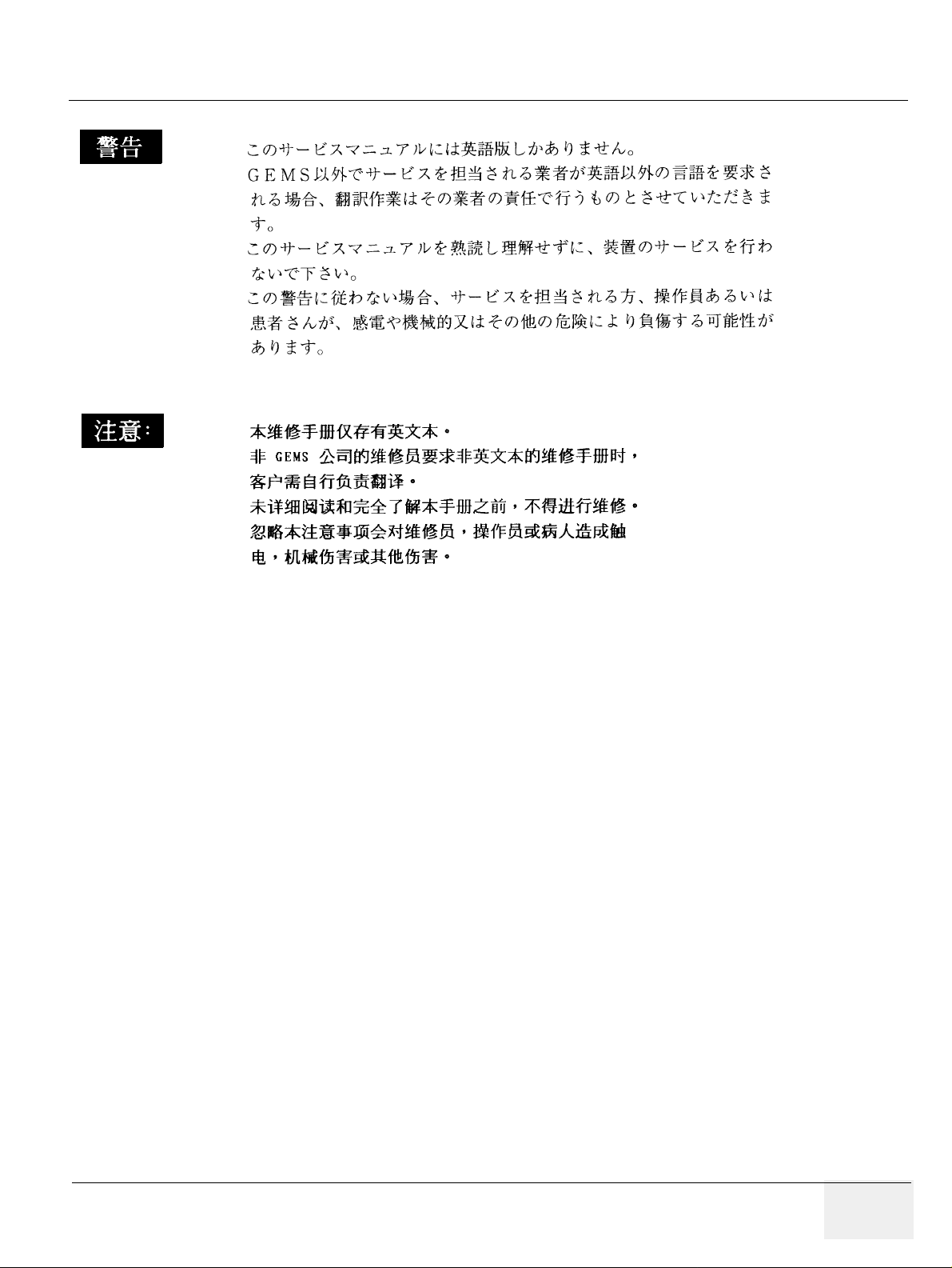
WARNING
AVERTISSEMENT
• THIS SERVICE MANUAL IS AVAILABLE IN ENGLISH ONLY.
• IF A CUSTOMER’S SERVICE PROVIDER REQUIRES A LANGUAGE OTHER
THAN ENGLISH, IT IS THE CUSTOMER’S RESPONSIBILITY TO PROVIDE
TRANSLATION SERVICES.
• DO NOT ATTEMPT TO SERVICE THE EQUIPMENT UNLESS THIS SERVICE
MANUAL HAS BEEN CONSULTED AND IS UNDERSTOOD.
• FAILURE TO HEED THIS WARNING MAY RESULT IN INJURY TO THE SERVICE
PROVIDER, OPERATOR OR PATIENT FROM ELECTRIC SHOCK,
MECHANICAL OR OTHER HAZARDS.
• CE MANUEL DE MAINTENANCE N’EST DISPONIBLE QU’EN ANGLAIS.
• SI LE TECHNICIEN DU CLIENT A BESOIN DE CE MANUEL DANS UNE AUTRE
LANGUE QUE L’ANGLAIS, C’EST AU CLIENT QU’IL INCOMBE DE LE FAIRE
TRADUIRE.
• NE PAS TENTER D’INTERVENTION SUR LES ÉQUIPEMENTS TANT QUE LE
MANUEL SERVICE N’A PAS ÉTÉ CONSULTÉ ET COMPRIS.
• LE NON-RESPECT DE CET AVERTISSEMENT PEUT ENTRAÎNER CHEZ LE
TECHNICIEN, L’OPÉRATEUR OU LE PATIENT DES BLESSURES DUES À DES
DANGERS ÉLECTRIQUES, MÉCANIQUES OU AUTRES.
WARNUNG
• DIESES KUNDENDIENST-HANDBUCH EXISTIERT NUR IN ENGLISCHER
SPRACHE.
• FALLS EIN FREMDER KUNDENDIENST EINE ANDERE SPRACHE BENÖTIGT,
IST ES AUFGABE DES KUNDEN FÜR EINE ENTSPRECHENDE ÜBERSETZUNG
ZU SORGEN.
• VERSUCHEN SIE NICHT, DAS GERÄT ZU REPARIEREN, BEVOR DIESES
KUNDENDIENST-HANDBUCH NICHT ZU RATE GEZOGEN UND VERSTANDEN
WURDE.
• WIRD DIESE WARNUNG NICHT BEACHTET, SO KANN ES ZU
VERLETZUNGEN DES KUNDENDIENSTTECHNIKERS, DES BEDIENERS ODER
DES PATIENTEN DURCH ELEKTRISCHE SCHLÄGE, MECHANISCHE ODER
SONSTIGE GEFAHREN KOMMEN.
Page iii
Page 6

GE MEDICAL SYSTEMS
PART NUMBER FB091565, REVISION 1 VIVID 5 SERVICE MANUAL
AVISO
ATENÇÃO
• ESTE MANUAL DE SERVICIO SÓLO EXISTE EN INGLÉS.
• SI ALGÚN PROVEEDOR DE SERVICIOS AJENO A GEMS SOLICITA UN IDIOMA
QUE NO SEA EL INGLÉS, ES RESPONSABILIDAD DEL CLIENTE OFRECER UN
SERVICIO DE TRADUCCIÓN.
• NO SE DEBERÁ DAR SERVICIO TÉCNICO AL EQUIPO, SIN HABER
CONSULTADO Y COMPRENDIDO ESTE MANUAL DE SERVICIO.
• LA NO OBSERVANCIA DEL PRESENTE AVISO PUEDE DAR LUGAR A QUE EL
PROVEEDOR DE SERVICIOS, EL OPERADOR O EL PACIENTE SUFRAN
LESIONES PROVOCADAS POR CAUSAS ELÉCTRICAS, MECÁNICAS O DE
OTRA NATURALEZA.
• ESTE MANUAL DE ASSISTÊNCIA TÉCNICA SÓ SE ENCONTRA DISPONÍVEL
EM INGLÊS.
• SE QUALQUER OUTRO SERVIÇO DE ASSISTÊNCIA TÉCNICA, QUE NÃO A
GEMS, SOLICITAR ESTES MANUAIS NOUTRO IDIOMA, É DA
RESPONSABILIDADE DO CLIENTE FORNECER OS SERVIÇOS DE
TRADUÇÃO.
• NÃO TENTE REPARAR O EQUIPAMENTO SEM TER CONSULTADO E
COMPREENDIDO ESTE MANUAL DE ASSISTÊNCIA TÉCNICA.
• O NÃO CUMPRIMENTO DESTE AVISO PODE POR EM PERIGO A SEGURANÇA
DO TÉCNICO, OPERADOR OU PACIENTE DEVIDO A‘ CHOQUES ELÉTRICOS,
MECÂNICOS OU OUTROS.
AVVERTENZA
• IL PRESENTE MANUALE DI MANUTENZIONE È DISPONIBILE SOLTANTO IN
INGLESE.
• SE UN ADDETTO ALLA MANUTENZIONE ESTERNO ALLA GEMS RICHIEDE IL
MANUALE IN UNA LINGUA DIVERSA, IL CLIENTE È TENUTO A PROVVEDERE
DIRETTAMENTE ALLA TRADUZIONE.
• SI PROCEDA ALLA MANUTENZIONE DELL’APPARECCHIATURA SOLO DOPO
AVER CONSULTATO IL PRESENTE MANUALE ED AVERNE COMPRESO IL
CONTENUTO.
• NON TENERE CONTO DELLA PRESENTE AVVERTENZA POTREBBE FAR
COMPIERE OPERAZIONI DA CUI DERIVINO LESIONI ALL’ADDETTO ALLA
MANUTENZIONE, ALL’UTILIZZATORE ED AL PAZIENTE PER
FOLGORAZIONE ELETTRICA, PER URTI MECCANICI OD ALTRI RISCHI.
Page iv
Page 7
GE MEDICAL SYSTEMS
P
ART NUMBER FB091565, REVISION 1 VIVID 5 SERVICE MANUAL
Page v
Page 8

GE MEDICAL SYSTEMS
PART NUMBER FB091565, REVISION 1 VIVID 5 SERVICE MANUAL
DAMAGE IN TRANSPORTATION
All packages should be closely examined at time of delivery. If damage is apparent
write “Damage In Shipment” on ALL copies of the freight or express bill BEFORE
delivery is accepted or “signed for” by a GE representative or hospital receiving
agent. Whether noted or concealed, damage MUST be reported to the carrier
immediately upon discovery, or in any event, within 14 days after receipt, and the
contents and containers held for inspection by the carrier. A transportation
company will not pay a claim for damage if an inspection is not requested within
this 14 day period.
CERTIFIED ELECTRICAL CONTRACTOR STATEMENT - FOR USA ONLY
All electrical Installations that are preliminary to positioning of the equipment at the
site prepared for the equipment shall be performed by licensed electrical
contractors. Other connections between pieces of electrical equipment,
calibrations and testing shall be performed by qualified GE Medical Systems
personnel. In performing all electrical work on these products, GE will use its own
specially trained field engineers. All of GE’s electrical work on these products will
comply with the requirements of the applicable electrical codes.
The purchaser of GE equipment shall only utilize qualified personnel (i.e., GE’s
field engineers, personnel of third-party service companies with equivalent training ,
or licensed electricians) to perform electrical servicing on the equipment.
OMISSIONS & ERRORS
If there are any omissions, errors or suggestions for improving this documen tation,
please contact the GE Healthcare Global Documentation Group with specific
information listing the system type, manual title, part number, revision number,
page number and suggestion details. Mail the information to : Service
Documentation, 4855 W. Electric Ave (EA-53), Milwaukee, WI 53219, USA.
GE Healthcare employees should use the iTrak System to report all documenta tion
errors or omissions.
Page vi
Page 9

GE MEDICAL SYSTEMS
P
ART NUMBER FB091565, REVISION 1 VIVID 5 SERVICE MANUAL
Revision History
REVISION DATE REASON FOR CHANGE
A 8. Aug. 2000 Initial release of manual
1 6. Jun. 2005 Updated with changes since the release of the first version of the manual.
List of Effected Pages
PAGES REVISION PAGES REVISION PAGES REVISION
Title Page 1 5-1 to 5-20 1 Back Cover N/A
i to xx 1 6-1 to 6-22 1
1-1 to 1-14 1 7-1 to 7-22 1
2-1 to 2-10 1 8-1 to 8-86 1
3-1 to 3-4 1 9-1 to 9-41 1
4-1 to 4-4 1 10-1 to 10-24 1
Page vii
Page 10

GE Medical Systems
PART NUMBER FB091565, REVISION 1 VIVID 5 SERVICE MANUAL
This page was intentionally left blank.
Page viii
Page 11

GE MEDICAL SYSTEMS
P
ART NUMBER FB091565, REVISION 1 VIVID 5 SERVICE MANUAL
Table of Contents
Chapter 1
Introduction . . . . . . . . . . . . . . . . . . . . . . . . . . . . . . . . . . . . . . . . . . . . . . . . . . . . . 1-1
Section 1-1
Overview . . . . . . . . . . . . . . . . . . . . . . . . . . . . . . . . . . . . . . . . . . . . . . . . . . . . . 1-1
1-1-1 Purpose of Chapter 1 . . . . . . . . . . . . . . . . . . . . . . . . . . . . . . . . . . . . . . . . . . . . . . . . . . . 1-1
1-1-2 Purpose of Service Manual. . . . . . . . . . . . . . . . . . . . . . . . . . . . . . . . . . . . . . . . . . . . . . . 1-1
1-1-2-1 Typical Users of the Service Manual . . . . . . . . . . . . . . . . . . . . . . . . . . . . . . . 1-2
1-1-3 Vivid 5 Models Covered by this Manual . . . . . . . . . . . . . . . . . . . . . . . . . . . . . . . . . . . . . 1-2
1-1-3-1 Overview. . . . . . . . . . . . . . . . . . . . . . . . . . . . . . . . . . . . . . . . . . . . . . . . . . . . . 1-2
1-1-3-2 System History - Hardware/Software Versions. . . . . . . . . . . . . . . . . . . . . . . . 1-3
1-1-3-3 Supported Probes. . . . . . . . . . . . . . . . . . . . . . . . . . . . . . . . . . . . . . . . . . . . . . 1-4
1-1-3-4 How to Turn the Scanner ON and OFF . . . . . . . . . . . . . . . . . . . . . . . . . . . . . 1-4
1-1-4 Purpose of Operator Manual(s) . . . . . . . . . . . . . . . . . . . . . . . . . . . . . . . . . . . . . . . . . . . 1-4
Section 1-2
Important Conventions . . . . . . . . . . . . . . . . . . . . . . . . . . . . . . . . . . . . . . . . . 1-5
1-2-1 Conventions Used in Book . . . . . . . . . . . . . . . . . . . . . . . . . . . . . . . . . . . . . . . . . . . . . . . 1-5
1-2-2 Standard Hazard Icons. . . . . . . . . . . . . . . . . . . . . . . . . . . . . . . . . . . . . . . . . . . . . . . . . . 1-6
Section 1-3
Safety Considerations . . . . . . . . . . . . . . . . . . . . . . . . . . . . . . . . . . . . . . . . . . 1-7
1-3-1 Introduction. . . . . . . . . . . . . . . . . . . . . . . . . . . . . . . . . . . . . . . . . . . . . . . . . . . . . . . . . . . 1-7
1-3-2 Human Safety. . . . . . . . . . . . . . . . . . . . . . . . . . . . . . . . . . . . . . . . . . . . . . . . . . . . . . . . . 1-7
1-3-3 Mechanical Safety . . . . . . . . . . . . . . . . . . . . . . . . . . . . . . . . . . . . . . . . . . . . . . . . . . . . . 1-8
1-3-4 Temperature Safety . . . . . . . . . . . . . . . . . . . . . . . . . . . . . . . . . . . . . . . . . . . . . . . . . . . . 1-9
1-3-5 Electrical Safety . . . . . . . . . . . . . . . . . . . . . . . . . . . . . . . . . . . . . . . . . . . . . . . . . . . . . . . 1-9
1-3-5-1 Safe Practices . . . . . . . . . . . . . . . . . . . . . . . . . . . . . . . . . . . . . . . . . . . . . . . . 1-9
1-3-6 Dangerous Procedure Warnings . . . . . . . . . . . . . . . . . . . . . . . . . . . . . . . . . . . . . . . . . . 1-9
1-3-7 Lockout/Tagout Requirements (For USA Only) . . . . . . . . . . . . . . . . . . . . . . . . . . . . . . . 1-9
1-3-8 Returning/Shipping Probes and Repair Parts. . . . . . . . . . . . . . . . . . . . . . . . . . . . . . . . 1-10
Section 1-4
Electromagnetic Compatibility (EMC) . . . . . . . . . . . . . . . . . . . . . . . . . . . . 1-10
1-4-1 What is EMC?. . . . . . . . . . . . . . . . . . . . . . . . . . . . . . . . . . . . . . . . . . . . . . . . . . . . . . . . 1-10
1-4-2 Compliance. . . . . . . . . . . . . . . . . . . . . . . . . . . . . . . . . . . . . . . . . . . . . . . . . . . . . . . . . . 1-10
1-4-3 Electrostatic Discharge (ESD) Prevention . . . . . . . . . . . . . . . . . . . . . . . . . . . . . . . . . . 1-11
Section 1-5
Customer Assistance. . . . . . . . . . . . . . . . . . . . . . . . . . . . . . . . . . . . . . . . . . 1-12
1-5-1 Contact Information . . . . . . . . . . . . . . . . . . . . . . . . . . . . . . . . . . . . . . . . . . . . . . . . . . . 1-12
1-5-2 System Manufacture. . . . . . . . . . . . . . . . . . . . . . . . . . . . . . . . . . . . . . . . . . . . . . . . . . . 1-13
Table of Contents Page ix
Page 12

GE MEDICAL SYSTEMS
PART NUMBER FB091565, REVISION 1 VIVID 5 SERVICE MANUAL
Chapter 2
Pre Installation . . . . . . . . . . . . . . . . . . . . . . . . . . . . . . . . . . . . . . . . . . . . . . . . . . . 2-1
Section 2-1
Purpose of Chapter . . . . . . . . . . . . . . . . . . . . . . . . . . . . . . . . . . . . . . . . . . . . . 2-1
Section 2-2
General Information. . . . . . . . . . . . . . . . . . . . . . . . . . . . . . . . . . . . . . . . . . . . . 2-1
2-2-1 Time and Manpower Requirements . . . . . . . . . . . . . . . . . . . . . . . . . . . . . . . . . . . . . . . 2-1
2-2-2 Important VIVID 5 Characteristics. . . . . . . . . . . . . . . . . . . . . . . . . . . . . . . . . . . . . . . . . 2-1
2-2-2-1 Physical Dimensions. . . . . . . . . . . . . . . . . . . . . . . . . . . . . . . . . . . . . . . . . . . 2-1
2-2-2-2 Weight without Monitor and Peripherals . . . . . . . . . . . . . . . . . . . . . . . . . . . . 2-2
2-2-2-3 Acoustic Noise Output: . . . . . . . . . . . . . . . . . . . . . . . . . . . . . . . . . . . . . . . . . 2-2
2-2-3 EMI Limitations . . . . . . . . . . . . . . . . . . . . . . . . . . . . . . . . . . . . . . . . . . . . . . . . . . . . . . . 2-2
2-2-4 Purchaser Responsibilities . . . . . . . . . . . . . . . . . . . . . . . . . . . . . . . . . . . . . . . . . . . . . . 2-4
Section 2-3
Facility Needs. . . . . . . . . . . . . . . . . . . . . . . . . . . . . . . . . . . . . . . . . . . . . . . . . . 2-5
2-3-1 Required Features . . . . . . . . . . . . . . . . . . . . . . . . . . . . . . . . . . . . . . . . . . . . . . . . . . . . 2-5
2-3-2 Desirable Features . . . . . . . . . . . . . . . . . . . . . . . . . . . . . . . . . . . . . . . . . . . . . . . . . . . . 2-5
2-3-3 Minimal Floor Plan Suggestion . . . . . . . . . . . . . . . . . . . . . . . . . . . . . . . . . . . . . . . . . . . 2-6
Section 2-4
Environmental Specifications . . . . . . . . . . . . . . . . . . . . . . . . . . . . . . . . . . . . 2-6
2-4-1 Systems . . . . . . . . . . . . . . . . . . . . . . . . . . . . . . . . . . . . . . . . . . . . . . . . . . . . . . . . . . . . 2-6
2-4-2 Probes. . . . . . . . . . . . . . . . . . . . . . . . . . . . . . . . . . . . . . . . . . . . . . . . . . . . . . . . . . . . . . 2-7
2-4-3 Cooling . . . . . . . . . . . . . . . . . . . . . . . . . . . . . . . . . . . . . . . . . . . . . . . . . . . . . . . . . . . . . 2-7
2-4-4 Lighting . . . . . . . . . . . . . . . . . . . . . . . . . . . . . . . . . . . . . . . . . . . . . . . . . . . . . . . . . . . . . 2-7
Section 2-5
Electrical Needs. . . . . . . . . . . . . . . . . . . . . . . . . . . . . . . . . . . . . . . . . . . . . . . . 2-8
2-5-1 VIVID 5 Power Requirements . . . . . . . . . . . . . . . . . . . . . . . . . . . . . . . . . . . . . . . . . . . . 2-8
2-5-2 Site Circuit Breaker . . . . . . . . . . . . . . . . . . . . . . . . . . . . . . . . . . . . . . . . . . . . . . . . . . . . 2-9
2-5-3 Site Power Outlets . . . . . . . . . . . . . . . . . . . . . . . . . . . . . . . . . . . . . . . . . . . . . . . . . . . . 2-9
2-5-4 Unit Power Plug . . . . . . . . . . . . . . . . . . . . . . . . . . . . . . . . . . . . . . . . . . . . . . . . . . . . . . 2-9
Page x
Page 13

GE MEDICAL SYSTEMS
P
ART NUMBER FB091565, REVISION 1 VIVID 5 SERVICE MANUAL
Chapter 3
Installation . . . . . . . . . . . . . . . . . . . . . . . . . . . . . . . . . . . . . . . . . . . . . . . . . . . . . . 3-1
Section 3-1
Purpose of Chapter . . . . . . . . . . . . . . . . . . . . . . . . . . . . . . . . . . . . . . . . . . . . 3-1
Section 3-2
General Information . . . . . . . . . . . . . . . . . . . . . . . . . . . . . . . . . . . . . . . . . . . . 3-1
3-2-1 Safety Reminders . . . . . . . . . . . . . . . . . . . . . . . . . . . . . . . . . . . . . . . . . . . . . . . . . . . . . 3-1
3-2-2 EMI Protection . . . . . . . . . . . . . . . . . . . . . . . . . . . . . . . . . . . . . . . . . . . . . . . . . . . . . . . 3-2
Section 3-3
Receiving and Unpacking the Equipment . . . . . . . . . . . . . . . . . . . . . . . . . . 3-2
Section 3-4
Preparing the Unit for Installation . . . . . . . . . . . . . . . . . . . . . . . . . . . . . . . . 3-3
3-4-1 Check the Unit Configuration . . . . . . . . . . . . . . . . . . . . . . . . . . . . . . . . . . . . . . . . . . . . 3-3
3-4-1-1 Check Voltage Settings . . . . . . . . . . . . . . . . . . . . . . . . . . . . . . . . . . . . . . . . 3-3
3-4-1-2 Video Formats . . . . . . . . . . . . . . . . . . . . . . . . . . . . . . . . . . . . . . . . . . . . . . . 3-3
Section 3-5
Completing the Installation . . . . . . . . . . . . . . . . . . . . . . . . . . . . . . . . . . . . . . 3-3
3-5-1 Electrical Safety Test . . . . . . . . . . . . . . . . . . . . . . . . . . . . . . . . . . . . . . . . . . . . . . . . . . 3-3
3-5-2 Paperwork. . . . . . . . . . . . . . . . . . . . . . . . . . . . . . . . . . . . . . . . . . . . . . . . . . . . . . . . . . . 3-3
3-5-2-1 User Manual . . . . . . . . . . . . . . . . . . . . . . . . . . . . . . . . . . . . . . . . . . . . . . . . . 3-3
Page xi
Page 14

GE MEDICAL SYSTEMS
PART NUMBER FB091565, REVISION 1 VIVID 5 SERVICE MANUAL
Chapter 4
Functional Checks . . . . . . . . . . . . . . . . . . . . . . . . . . . . . . . . . . . . . . . . . . . . . . . . 4-1
Section 4-1
Purpose of chapter . . . . . . . . . . . . . . . . . . . . . . . . . . . . . . . . . . . . . . . . . . . . . 4-1
Section 4-2
General Procedures. . . . . . . . . . . . . . . . . . . . . . . . . . . . . . . . . . . . . . . . . . . . . 4-1
4-2-1 Connect a Probe . . . . . . . . . . . . . . . . . . . . . . . . . . . . . . . . . . . . . . . . . . . . . . . . . . . . . . 4-1
4-2-2 Power On/Boot Up . . . . . . . . . . . . . . . . . . . . . . . . . . . . . . . . . . . . . . . . . . . . . . . . . . . . 4-1
4-2-3 Stand By/Power OFF . . . . . . . . . . . . . . . . . . . . . . . . . . . . . . . . . . . . . . . . . . . . . . . . . . 4-1
Section 4-3
Functional Checks. . . . . . . . . . . . . . . . . . . . . . . . . . . . . . . . . . . . . . . . . . . . . . 4-2
4-3-1 Basic System Checks . . . . . . . . . . . . . . . . . . . . . . . . . . . . . . . . . . . . . . . . . . . . . . . . . . 4-2
4-3-2 Check of Options. . . . . . . . . . . . . . . . . . . . . . . . . . . . . . . . . . . . . . . . . . . . . . . . . . . . . . 4-2
Section 4-4
Mechanical Adjustments. . . . . . . . . . . . . . . . . . . . . . . . . . . . . . . . . . . . . . . . . 4-2
4-4-1 Check of Wheels/Locks/Brakes . . . . . . . . . . . . . . . . . . . . . . . . . . . . . . . . . . . . . . . . . . 4-2
Section 4-5
Site Log. . . . . . . . . . . . . . . . . . . . . . . . . . . . . . . . . . . . . . . . . . . . . . . . . . . . . . . 4-3
Page xii
Page 15

GE MEDICAL SYSTEMS
P
ART NUMBER FB091565, REVISION 1 VIVID 5 SERVICE MANUAL
Chapter 5
Theory. . . . . . . . . . . . . . . . . . . . . . . . . . . . . . . . . . . . . . . . . . . . . . . . . . . . . . . . . . 5-1
Section 5-1
Purpose of chapter. . . . . . . . . . . . . . . . . . . . . . . . . . . . . . . . . . . . . . . . . . . . . 5-1
Section 5-2
VIVID 5 Description . . . . . . . . . . . . . . . . . . . . . . . . . . . . . . . . . . . . . . . . . . . . 5-1
5-2-1 General Information . . . . . . . . . . . . . . . . . . . . . . . . . . . . . . . . . . . . . . . . . . . . . . . . . . . 5-1
5-2-2 Major Components . . . . . . . . . . . . . . . . . . . . . . . . . . . . . . . . . . . . . . . . . . . . . . . . . . . . 5-2
5-2-3 Ultrasound Data Path . . . . . . . . . . . . . . . . . . . . . . . . . . . . . . . . . . . . . . . . . . . . . . . . . . 5-3
5-2-4 Functional Subsystems. . . . . . . . . . . . . . . . . . . . . . . . . . . . . . . . . . . . . . . . . . . . . . . . . 5-3
5-2-4-1 Front End (FE) . . . . . . . . . . . . . . . . . . . . . . . . . . . . . . . . . . . . . . . . . . . . . . . 5-3
5-2-4-2 Mid Processors. . . . . . . . . . . . . . . . . . . . . . . . . . . . . . . . . . . . . . . . . . . . . . . 5-3
5-2-4-3 Display and Control . . . . . . . . . . . . . . . . . . . . . . . . . . . . . . . . . . . . . . . . . . . 5-3
5-2-4-4 Keyboard, I/O and Peripherals . . . . . . . . . . . . . . . . . . . . . . . . . . . . . . . . . . . 5-3
Section 5-3
Circuit Boards. . . . . . . . . . . . . . . . . . . . . . . . . . . . . . . . . . . . . . . . . . . . . . . . . 5-4
5-3-1 Front End (FE) Boards . . . . . . . . . . . . . . . . . . . . . . . . . . . . . . . . . . . . . . . . . . . . . . . . . 5-4
5-3-2 Mid Processor Boards . . . . . . . . . . . . . . . . . . . . . . . . . . . . . . . . . . . . . . . . . . . . . . . . . 5-4
5-3-3 Display and Control Boards . . . . . . . . . . . . . . . . . . . . . . . . . . . . . . . . . . . . . . . . . . . . . 5-4
5-3-4 Keyboard, I/O and Peripherals . . . . . . . . . . . . . . . . . . . . . . . . . . . . . . . . . . . . . . . . . . . 5-4
Section 5-4
Power System. . . . . . . . . . . . . . . . . . . . . . . . . . . . . . . . . . . . . . . . . . . . . . . . . 5-5
5-4-1 AC Power Supply with ON/OFF Control. . . . . . . . . . . . . . . . . . . . . . . . . . . . . . . . . . . . 5-5
5-4-2 AC Power Outlets . . . . . . . . . . . . . . . . . . . . . . . . . . . . . . . . . . . . . . . . . . . . . . . . . . . . . 5-5
5-4-3 DC Power . . . . . . . . . . . . . . . . . . . . . . . . . . . . . . . . . . . . . . . . . . . . . . . . . . . . . . . . . . . 5-6
5-4-4 3.3V DC/DC Converter . . . . . . . . . . . . . . . . . . . . . . . . . . . . . . . . . . . . . . . . . . . . . . . . . 5-6
5-4-5 High Voltage Power Supply . . . . . . . . . . . . . . . . . . . . . . . . . . . . . . . . . . . . . . . . . . . . . 5-7
5-4-6 Power Distribution . . . . . . . . . . . . . . . . . . . . . . . . . . . . . . . . . . . . . . . . . . . . . . . . . . . . 5-8
5-4-7 Front End and Mid. Processors Block Diagram 5-9
5-4-8 Display, Control and Input/Output (I/O) Block Diagram 5-10
5-4-9 Front End Block Diagram 5-11
5-4-10 Mid Processor Block Diagram 5-12
5-4-11 Display Block Diagram 5-13
5-4-12 Internal I/O and External I/O Block Diagram 5-14
5-4-13 Connector Layout of Vivid 5 Internal I/O-2 Board (IIO-2) . . . . . . . . . . . . . . . . . . . . . . 5-15
5-4-14 Signal List, Internal I/O-2 (IIO-2). . . . . . . . . . . . . . . . . . . . . . . . . . . . . . . . . . . . . . . . . 5-16
5-4-15 Connector Layout of Vivid 5 External I/O-2 Board (EIO-2)) . . . . . . . . . . . . . . . . . . . . 5-17
5-4-16 Insulation Diagram, External I/O-2 . . . . . . . . . . . . . . . . . . . . . . . . . . . . . . . . . . . . . . . 5-18
5-4-17 Signal Insulation List, External I/O-2 (EIO-2) . . . . . . . . . . . . . . . . . . . . . . . . . . . . . . . 5-19
Section 5-5
Video Specifications for VIVID 5. . . . . . . . . . . . . . . . . . . . . . . . . . . . . . . . . 5-20
5-5-1 PAL Video Specifications . . . . . . . . . . . . . . . . . . . . . . . . . . . . . . . . . . . . . . . . . . . . . . 5-20
5-5-2 NTSC Video Specifications. . . . . . . . . . . . . . . . . . . . . . . . . . . . . . . . . . . . . . . . . . . . . 5-20
Page xiii
Page 16

GE MEDICAL SYSTEMS
PART NUMBER FB091565, REVISION 1 VIVID 5 SERVICE MANUAL
Chapter 6
Service Adjustments . . . . . . . . . . . . . . . . . . . . . . . . . . . . . . . . . . . . . . . . . . . . . . 6-1
Section 6-1
Introduction . . . . . . . . . . . . . . . . . . . . . . . . . . . . . . . . . . . . . . . . . . . . . . . . . . . 6-1
Section 6-2
Regulatory . . . . . . . . . . . . . . . . . . . . . . . . . . . . . . . . . . . . . . . . . . . . . . . . . . . . 6-1
Section 6-3
Calibration . . . . . . . . . . . . . . . . . . . . . . . . . . . . . . . . . . . . . . . . . . . . . . . . . . . . 6-1
6-3-1 Setup Menu Selection. . . . . . . . . . . . . . . . . . . . . . . . . . . . . . . . . . . . . . . . . . . . . . . . . . 6-1
6-3-2 Date, Time and Hospital Name Verification . . . . . . . . . . . . . . . . . . . . . . . . . . . . . . . . . 6-1
Section 6-4
Performance Test . . . . . . . . . . . . . . . . . . . . . . . . . . . . . . . . . . . . . . . . . . . . . . 6-1
6-4-1 Introduction . . . . . . . . . . . . . . . . . . . . . . . . . . . . . . . . . . . . . . . . . . . . . . . . . . . . . . . . . . 6-1
6-4-1-1 Abstract. . . . . . . . . . . . . . . . . . . . . . . . . . . . . . . . . . . . . . . . . . . . . . . . . . . . . 6-1
6-4-2 Scope . . . . . . . . . . . . . . . . . . . . . . . . . . . . . . . . . . . . . . . . . . . . . . . . . . . . . . . . . . . . . . 6-2
6-4-3 Initial Checks. . . . . . . . . . . . . . . . . . . . . . . . . . . . . . . . . . . . . . . . . . . . . . . . . . . . . . . . . 6-2
6-4-3-1 Configuration/Test Menu. . . . . . . . . . . . . . . . . . . . . . . . . . . . . . . . . . . . . . . . 6-2
6-4-3-2 Software . . . . . . . . . . . . . . . . . . . . . . . . . . . . . . . . . . . . . . . . . . . . . . . . . . . . 6-2
6-4-3-3 Hardware. . . . . . . . . . . . . . . . . . . . . . . . . . . . . . . . . . . . . . . . . . . . . . . . . . . . 6-2
6-4-3-4 User Interface . . . . . . . . . . . . . . . . . . . . . . . . . . . . . . . . . . . . . . . . . . . . . . . . 6-2
6-4-4 Automatic Tests . . . . . . . . . . . . . . . . . . . . . . . . . . . . . . . . . . . . . . . . . . . . . . . . . . . . . . 6-2
6-4-4-1 Diagnostic Test . . . . . . . . . . . . . . . . . . . . . . . . . . . . . . . . . . . . . . . . . . . . . . . 6-2
6-4-5 Front Panel Test . . . . . . . . . . . . . . . . . . . . . . . . . . . . . . . . . . . . . . . . . . . . . . . . . . . . . . 6-3
6-4-5-1 Start of Test. . . . . . . . . . . . . . . . . . . . . . . . . . . . . . . . . . . . . . . . . . . . . . . . . . 6-3
6-4-5-2 Display Test . . . . . . . . . . . . . . . . . . . . . . . . . . . . . . . . . . . . . . . . . . . . . . . . . 6-4
6-4-5-3 LED Test. . . . . . . . . . . . . . . . . . . . . . . . . . . . . . . . . . . . . . . . . . . . . . . . . . . . 6-4
6-4-5-4 Key Test . . . . . . . . . . . . . . . . . . . . . . . . . . . . . . . . . . . . . . . . . . . . . . . . . . . . 6-4
6-4-5-5 Rotary Knob Test . . . . . . . . . . . . . . . . . . . . . . . . . . . . . . . . . . . . . . . . . . . . . 6-4
6-4-5-6 Paddle Stick Test . . . . . . . . . . . . . . . . . . . . . . . . . . . . . . . . . . . . . . . . . . . . . 6-4
6-4-5-7 TGC Slide pot. Test. . . . . . . . . . . . . . . . . . . . . . . . . . . . . . . . . . . . . . . . . . . . 6-4
6-4-5-8 Trackball Test . . . . . . . . . . . . . . . . . . . . . . . . . . . . . . . . . . . . . . . . . . . . . . . . 6-4
6-4-6 Transmit Pulse Test . . . . . . . . . . . . . . . . . . . . . . . . . . . . . . . . . . . . . . . . . . . . . . . . . . . 6-5
6-4-7 Transmit Trigger (TXTRIG) Test . . . . . . . . . . . . . . . . . . . . . . . . . . . . . . . . . . . . . . . . . . 6-5
6-4-8 ATGC Test . . . . . . . . . . . . . . . . . . . . . . . . . . . . . . . . . . . . . . . . . . . . . . . . . . . . . . . . . . 6-5
6-4-9 High Voltage Test . . . . . . . . . . . . . . . . . . . . . . . . . . . . . . . . . . . . . . . . . . . . . . . . . . . . . 6-6
6-4-9-1 HV1 and HV2 Tests . . . . . . . . . . . . . . . . . . . . . . . . . . . . . . . . . . . . . . . . . . . 6-6
6-4-10 DC Voltage Test . . . . . . . . . . . . . . . . . . . . . . . . . . . . . . . . . . . . . . . . . . . . . . . . . . . . . . 6-6
6-4-10-1 Measuring DC Voltages on the INT I/O Power Connector(s):. . . . . . . . . . . . 6-6
6-4-10-2 Watching LEDs . . . . . . . . . . . . . . . . . . . . . . . . . . . . . . . . . . . . . . . . . . . . . . . 6-7
6-4-10-3 Measuring DC Voltages on th e Motherboard.. . . . . . . . . . . . . . . . . . . . . . . . 6-7
6-4-11 Peripheral and I/O Tests . . . . . . . . . . . . . . . . . . . . . . . . . . . . . . . . . . . . . . . . . . . . . . . . 6-8
6-4-11-1 PAL/NTSC Setting . . . . . . . . . . . . . . . . . . . . . . . . . . . . . . . . . . . . . . . . . . . . 6-8
6-4-11-2 Record and Playback . . . . . . . . . . . . . . . . . . . . . . . . . . . . . . . . . . . . . . . . . . 6-8
6-4-11-3 Printer Test . . . . . . . . . . . . . . . . . . . . . . . . . . . . . . . . . . . . . . . . . . . . . . . . . . 6-8
6-4-11-4 Footswitch. . . . . . . . . . . . . . . . . . . . . . . . . . . . . . . . . . . . . . . . . . . . . . . . . . . 6-8
6-4-12 External I/O Tests . . . . . . . . . . . . . . . . . . . . . . . . . . . . . . . . . . . . . . . . . . . . . . . . . . . . . 6-8
6-4-12-1 Video out. . . . . . . . . . . . . . . . . . . . . . . . . . . . . . . . . . . . . . . . . . . . . . . . . . . . 6-8
6-4-12-2 S-VHS Out . . . . . . . . . . . . . . . . . . . . . . . . . . . . . . . . . . . . . . . . . . . . . . . . . . 6-8
Page xiv
Page 17

GE MEDICAL SYSTEMS
P
ART NUMBER FB091565, REVISION 1 VIVID 5 SERVICE MANUAL
6-4-12-3 RGBS Out. . . . . . . . . . . . . . . . . . . . . . . . . . . . . . . . . . . . . . . . . . . . . . . . . . . 6-8
6-4-12-4 MAC Interface Test - Stand Alone MAC only . . . . . . . . . . . . . . . . . . . . . . . . 6-9
6-4-12-5 ECG . . . . . . . . . . . . . . . . . . . . . . . . . . . . . . . . . . . . . . . . . . . . . . . . . . . . . . . 6-9
6-4-12-6 Phono . . . . . . . . . . . . . . . . . . . . . . . . . . . . . . . . . . . . . . . . . . . . . . . . . . . . . . 6-9
6-4-12-7 Respiration . . . . . . . . . . . . . . . . . . . . . . . . . . . . . . . . . . . . . . . . . . . . . . . . . . 6-9
6-4-12-8 Pressure . . . . . . . . . . . . . . . . . . . . . . . . . . . . . . . . . . . . . . . . . . . . . . . . . . . . 6-9
6-4-13 Integrated Mac . . . . . . . . . . . . . . . . . . . . . . . . . . . . . . . . . . . . . . . . . . . . . . . . . . . . . . . 6-9
6-4-13-1 Setup Check. . . . . . . . . . . . . . . . . . . . . . . . . . . . . . . . . . . . . . . . . . . . . . . . . 6-9
6-4-13-2 Macintosh with Continuous Capture. . . . . . . . . . . . . . . . . . . . . . . . . . . . . . . 6-9
6-4-13-3 Communication with Scanner. . . . . . . . . . . . . . . . . . . . . . . . . . . . . . . . . . . 6-10
6-4-14 Mechanical Check . . . . . . . . . . . . . . . . . . . . . . . . . . . . . . . . . . . . . . . . . . . . . . . . . . . 6-11
6-4-14-1 Checking Brakes. . . . . . . . . . . . . . . . . . . . . . . . . . . . . . . . . . . . . . . . . . . . . 6-11
6-4-14-2 Checking Monitor Tilt . . . . . . . . . . . . . . . . . . . . . . . . . . . . . . . . . . . . . . . . . 6-11
6-4-15 Hardware Check. . . . . . . . . . . . . . . . . . . . . . . . . . . . . . . . . . . . . . . . . . . . . . . . . . . . . 6-12
6-4-15-1 Screen Switching . . . . . . . . . . . . . . . . . . . . . . . . . . . . . . . . . . . . . . . . . . . . 6-12
6-4-15-2 VCR Recording. . . . . . . . . . . . . . . . . . . . . . . . . . . . . . . . . . . . . . . . . . . . . . 6-12
6-4-15-3 EchoPac-3D . . . . . . . . . . . . . . . . . . . . . . . . . . . . . . . . . . . . . . . . . . . . . . . . 6-12
6-4-16 Monitor Setup (Adjust if Necessary, ONLY) . . . . . . . . . . . . . . . . . . . . . . . . . . . . . . . . 6-12
6-4-16-1 Screen Manager (Main Menu) . . . . . . . . . . . . . . . . . . . . . . . . . . . . . . . . . . 6-13
6-4-16-2 Pre Settings . . . . . . . . . . . . . . . . . . . . . . . . . . . . . . . . . . . . . . . . . . . . . . . . 6-13
6-4-16-3 Adjust Convergence . . . . . . . . . . . . . . . . . . . . . . . . . . . . . . . . . . . . . . . . . . 6-13
6-4-16-4 Geometry and Size. . . . . . . . . . . . . . . . . . . . . . . . . . . . . . . . . . . . . . . . . . . 6-13
6-4-17 Functional Test . . . . . . . . . . . . . . . . . . . . . . . . . . . . . . . . . . . . . . . . . . . . . . . . . . . . . . 6-13
6-4-17-1 2D Controls. . . . . . . . . . . . . . . . . . . . . . . . . . . . . . . . . . . . . . . . . . . . . . . . . 6-13
6-4-17-2 Doppler Controls. . . . . . . . . . . . . . . . . . . . . . . . . . . . . . . . . . . . . . . . . . . . . 6-14
6-4-17-3 Color Flow controls. . . . . . . . . . . . . . . . . . . . . . . . . . . . . . . . . . . . . . . . . . . 6-14
6-4-17-4 MPTE Test (PAMPTE) . . . . . . . . . . . . . . . . . . . . . . . . . . . . . . . . . . . . . . . . 6-15
6-4-18 M-Mode Tests. . . . . . . . . . . . . . . . . . . . . . . . . . . . . . . . . . . . . . . . . . . . . . . . . . . . . . . 6-15
6-4-18-1 Linearity . . . . . . . . . . . . . . . . . . . . . . . . . . . . . . . . . . . . . . . . . . . . . . . . . . . 6-15
6-4-18-2 Color M-mode Test. . . . . . . . . . . . . . . . . . . . . . . . . . . . . . . . . . . . . . . . . . . 6-15
6-4-19 Image Quality and Noise . . . . . . . . . . . . . . . . . . . . . . . . . . . . . . . . . . . . . . . . . . . . . . 6-16
6-4-19-1 2D Mode. . . . . . . . . . . . . . . . . . . . . . . . . . . . . . . . . . . . . . . . . . . . . . . . . . . 6-16
6-4-19-2 Doppler Mode. . . . . . . . . . . . . . . . . . . . . . . . . . . . . . . . . . . . . . . . . . . . . . . 6-16
6-4-19-3 Color Flow Mode. . . . . . . . . . . . . . . . . . . . . . . . . . . . . . . . . . . . . . . . . . . . . 6-16
6-4-20 Options . . . . . . . . . . . . . . . . . . . . . . . . . . . . . . . . . . . . . . . . . . . . . . . . . . . . . . . . . . . . 6-16
6-4-21 Hardware Revision Level . . . . . . . . . . . . . . . . . . . . . . . . . . . . . . . . . . . . . . . . . . . . . . 6-16
Section 6-5
Probe Element Test . . . . . . . . . . . . . . . . . . . . . . . . . . . . . . . . . . . . . . . . . . . 6-17
Section 6-6
Element to Channel Mapping . . . . . . . . . . . . . . . . . . . . . . . . . . . . . . . . . . . 6-18
6-6-1 Introduction. . . . . . . . . . . . . . . . . . . . . . . . . . . . . . . . . . . . . . . . . . . . . . . . . . . . . . . . . 6-18
6-6-2 192 Element Probes . . . . . . . . . . . . . . . . . . . . . . . . . . . . . . . . . . . . . . . . . . . . . . . . . . 6-18
6-6-2-1 Troubleshooting Technique . . . . . . . . . . . . . . . . . . . . . . . . . . . . . . . . . . . . 6-19
6-6-3 128 Element Probes . . . . . . . . . . . . . . . . . . . . . . . . . . . . . . . . . . . . . . . . . . . . . . . . . . 6-20
6-6-4 96 Element Probes . . . . . . . . . . . . . . . . . . . . . . . . . . . . . . . . . . . . . . . . . . . . . . . . . . . 6-21
6-6-5 64 Element Probes . . . . . . . . . . . . . . . . . . . . . . . . . . . . . . . . . . . . . . . . . . . . . . . . . . . 6-22
6-6-6 Stand Alone Doppler Probes . . . . . . . . . . . . . . . . . . . . . . . . . . . . . . . . . . . . . . . . . . . 6-22
Page xv
Page 18

GE MEDICAL SYSTEMS
PART NUMBER FB091565, REVISION 1 VIVID 5 SERVICE MANUAL
Chapter 7
Diagnostics. . . . . . . . . . . . . . . . . . . . . . . . . . . . . . . . . . . . . . . . . . . . . . . . . . . . . . 7-1
Section 7-1
Minimum Boot Configuration . . . . . . . . . . . . . . . . . . . . . . . . . . . . . . . . . . . . 7-1
7-1-1 Minimum Board Configuration for System to Boot . . . . . . . . . . . . . . . . . . . . . . . . . . . . 7-1
7-1-1-1 Boards Needed to Boot to the So-called "No-mode" Screen . . . . . . . . . . . . 7-1
7-1-1-2 Boards Needed for 2D Mode . . . . . . . . . . . . . . . . . . . . . . . . . . . . . . . . . . . . 7-1
7-1-1-3 Boards Needed for Any Test Purposes. . . . . . . . . . . . . . . . . . . . . . . . . . . . . 7-1
7-1-1-4 Boards That May be Left Out Without any Special Modifications. . . . . . . . . 7-2
7-1-1-5 Boards That Must be Replaced by a VME Jumpe r When Removed . . . . . . 7-2
7-1-2 Minimum Cable Configuration for System to Boot . . . . . . . . . . . . . . . . . . . . . . . . . . . . 7-2
Section 7-2
Faults Diagnosis . . . . . . . . . . . . . . . . . . . . . . . . . . . . . . . . . . . . . . . . . . . . . . . 7-3
7-2-1 Instructions on How to Use This chapter . . . . . . . . . . . . . . . . . . . . . . . . . . . . . . . . . . . 7-3
7-2-2 Fault Classification Overview . . . . . . . . . . . . . . . . . . . . . . . . . . . . . . . . . . . . . . . . . . . . 7-3
Section 7-3
Start-up Problems . . . . . . . . . . . . . . . . . . . . . . . . . . . . . . . . . . . . . . . . . . . . . . 7-4
7-3-1 System Doesn’t Boot. . . . . . . . . . . . . . . . . . . . . . . . . . . . . . . . . . . . . . . . . . . . . . . . . . . 7-4
7-3-2 Start-up Problems, AC Power Related . . . . . . . . . . . . . . . . . . . . . . . . . . . . . . . . . . . . . 7-5
7-3-3 Start-up Problems, DC Power Related (AC Power ok). . . . . . . . . . . . . . . . . . . . . . . . . 7-6
7-3-4 Start-up Problems, System Doesn’t Boot, Possible Hard Disk Problem. . . . . . . . . . . . 7-7
7-3-5 Start-up Problems, System Doesn’t Boot, Possible Board Problem. . . . . . . . . . . . . . . 7-8
Section 7-4
Display Problems. . . . . . . . . . . . . . . . . . . . . . . . . . . . . . . . . . . . . . . . . . . . . . . 7-9
7-4-1 No Display on Monitor, Monitor Display is Black (System Appears to Have Booted). . 7-9
7-4-2 No Display in the Image Field . . . . . . . . . . . . . . . . . . . . . . . . . . . . . . . . . . . . . . . . . . . 7-10
7-4-3 Data in Image Field Frozen. . . . . . . . . . . . . . . . . . . . . . . . . . . . . . . . . . . . . . . . . . . . . 7-11
7-4-4 Only Noise in Image Field . . . . . . . . . . . . . . . . . . . . . . . . . . . . . . . . . . . . . . . . . . . . . 7-12
Section 7-5
Peripheral Problems . . . . . . . . . . . . . . . . . . . . . . . . . . . . . . . . . . . . . . . . . . . 7-13
7-5-1 VCR Related Problems. . . . . . . . . . . . . . . . . . . . . . . . . . . . . . . . . . . . . . . . . . . . . . . . 7-13
Section 7-6
Front Panel Problems . . . . . . . . . . . . . . . . . . . . . . . . . . . . . . . . . . . . . . . . . . 7-15
7-6-1 No Response to Front Panel Controls . . . . . . . . . . . . . . . . . . . . . . . . . . . . . . . . . . . . 7-15
Section 7-7
Probe Problems. . . . . . . . . . . . . . . . . . . . . . . . . . . . . . . . . . . . . . . . . . . . . . . 7-16
7-7-1 Probe Recognition and Switching Problems. . . . . . . . . . . . . . . . . . . . . . . . . . . . . . . . 7-16
Section 7-8
Specific 2D Problems . . . . . . . . . . . . . . . . . . . . . . . . . . . . . . . . . . . . . . . . . . 7-17
7-8-1 “Frozen” Images, Images with Artifacts. . . . . . . . . . . . . . . . . . . . . . . . . . . . . . . . . . . . 7-17
7-8-2 Noisy Images . . . . . . . . . . . . . . . . . . . . . . . . . . . . . . . . . . . . . . . . . . . . . . . . . . . . . . . 7-17
7-8-3 Poor Image Quality . . . . . . . . . . . . . . . . . . . . . . . . . . . . . . . . . . . . . . . . . . . . . . . . . . . 7-18
7-8-4 Only Center Part of FLA Probes Image Shown . . . . . . . . . . . . . . . . . . . . . . . . . . . . . 7-18
Page xvi
Page 19

GE MEDICAL SYSTEMS
P
ART NUMBER FB091565, REVISION 1 VIVID 5 SERVICE MANUAL
Section 7-9
Specific Color Flow Problems. . . . . . . . . . . . . . . . . . . . . . . . . . . . . . . . . . . 7-19
7-9-1 No Color Flow (2D ok) or Frozen Color Flow . . . . . . . . . . . . . . . . . . . . . . . . . . . . . . . 7-19
7-9-2 Noise Problems . . . . . . . . . . . . . . . . . . . . . . . . . . . . . . . . . . . . . . . . . . . . . . . . . . . . . 7-19
7-9-3 Poor Flow Quality . . . . . . . . . . . . . . . . . . . . . . . . . . . . . . . . . . . . . . . . . . . . . . . . . . . . 7-19
Section 7-10
Specific Doppler Problems . . . . . . . . . . . . . . . . . . . . . . . . . . . . . . . . . . . . . 7-20
7-10-1 No Doppler (2D ok). . . . . . . . . . . . . . . . . . . . . . . . . . . . . . . . . . . . . . . . . . . . . . . . . . . 7-20
7-10-2 Noisy Doppler . . . . . . . . . . . . . . . . . . . . . . . . . . . . . . . . . . . . . . . . . . . . . . . . . . . . . . . 7-20
Section 7-11
Analog Traces (ECG, Phono, Pressure, Respiration). . . . . . . . . . . . . . . . 7-21
7-11-1 Unstable ECG. . . . . . . . . . . . . . . . . . . . . . . . . . . . . . . . . . . . . . . . . . . . . . . . . . . . . . . 7-21
Section 7-12
Misc. Problems. . . . . . . . . . . . . . . . . . . . . . . . . . . . . . . . . . . . . . . . . . . . . . . 7-22
7-12-1 Fan Related Problems . . . . . . . . . . . . . . . . . . . . . . . . . . . . . . . . . . . . . . . . . . . . . . . . 7-22
Page xvii
Page 20

GE MEDICAL SYSTEMS
PART NUMBER FB091565, REVISION 1 VIVID 5 SERVICE MANUAL
Chapter 8
Replacement Procedures . . . . . . . . . . . . . . . . . . . . . . . . . . . . . . . . . . . . . . . . . . 8-1
Section 8-1
Overview. . . . . . . . . . . . . . . . . . . . . . . . . . . . . . . . . . . . . . . . . . . . . . . . . . . . . . 8-1
8-1-1 Purpose of Chapter 8 . . . . . . . . . . . . . . . . . . . . . . . . . . . . . . . . . . . . . . . . . . . . . . . . . . 8-1
8-1-2 Returning/Shipping Probes and Repair Parts . . . . . . . . . . . . . . . . . . . . . . . . . . . . . . . . 8-2
8-1-3 Warnings. . . . . . . . . . . . . . . . . . . . . . . . . . . . . . . . . . . . . . . . . . . . . . . . . . . . . . . . . . . . 8-2
Section 8-2
AC Power Replacement Procedure . . . . . . . . . . . . . . . . . . . . . . . . . . . . . . . . 8-3
8-2-1 Introduction . . . . . . . . . . . . . . . . . . . . . . . . . . . . . . . . . . . . . . . . . . . . . . . . . . . . . . . . . . 8-3
8-2-2 Tool Requirements . . . . . . . . . . . . . . . . . . . . . . . . . . . . . . . . . . . . . . . . . . . . . . . . . . . . 8-3
8-2-3 Description . . . . . . . . . . . . . . . . . . . . . . . . . . . . . . . . . . . . . . . . . . . . . . . . . . . . . . . . . . 8-3
8-2-3-1 Prepare the system for AC Power Replacement . . . . . . . . . . . . . . . . . . . . . 8-3
8-2-3-2 Remove the AC Power . . . . . . . . . . . . . . . . . . . . . . . . . . . . . . . . . . . . . . . . . 8-4
8-2-3-3 Install the New AC Power . . . . . . . . . . . . . . . . . . . . . . . . . . . . . . . . . . . . . . . 8-4
Section 8-3
External I/O Replacement Procedure. . . . . . . . . . . . . . . . . . . . . . . . . . . . . . . 8-5
8-3-1 Introduction . . . . . . . . . . . . . . . . . . . . . . . . . . . . . . . . . . . . . . . . . . . . . . . . . . . . . . . . . . 8-5
8-3-2 Tool requirements . . . . . . . . . . . . . . . . . . . . . . . . . . . . . . . . . . . . . . . . . . . . . . . . . . . . . 8-5
8-3-3 Description . . . . . . . . . . . . . . . . . . . . . . . . . . . . . . . . . . . . . . . . . . . . . . . . . . . . . . . . . . 8-5
Section 8-4
DC Power Replacement Procedure . . . . . . . . . . . . . . . . . . . . . . . . . . . . . . . . 8-6
8-4-1 Introduction . . . . . . . . . . . . . . . . . . . . . . . . . . . . . . . . . . . . . . . . . . . . . . . . . . . . . . . . . . 8-6
8-4-2 Tool requirements . . . . . . . . . . . . . . . . . . . . . . . . . . . . . . . . . . . . . . . . . . . . . . . . . . . . . 8-6
8-4-3 Description . . . . . . . . . . . . . . . . . . . . . . . . . . . . . . . . . . . . . . . . . . . . . . . . . . . . . . . . . . 8-6
Section 8-5
Front Panel Assembly & Trackball Replacement Procedure . . . . . . . . . . . 8-7
8-5-1 Introduction . . . . . . . . . . . . . . . . . . . . . . . . . . . . . . . . . . . . . . . . . . . . . . . . . . . . . . . . . . 8-7
8-5-2 Tool Requirements . . . . . . . . . . . . . . . . . . . . . . . . . . . . . . . . . . . . . . . . . . . . . . . . . . . . 8-7
8-5-3 Front Panel Replacement . . . . . . . . . . . . . . . . . . . . . . . . . . . . . . . . . . . . . . . . . . . . . . . 8-7
8-5-4 Trackball Replacement Description . . . . . . . . . . . . . . . . . . . . . . . . . . . . . . . . . . . . . . . 8-7
Section 8-6
QWERTY (Alphanumeric) Keyboard Replacement Description . . . . . . . . . 8-8
Section 8-7
Fan Replacement Procedure . . . . . . . . . . . . . . . . . . . . . . . . . . . . . . . . . . . . . 8-9
8-7-1 Introduction . . . . . . . . . . . . . . . . . . . . . . . . . . . . . . . . . . . . . . . . . . . . . . . . . . . . . . . . . . 8-9
8-7-2 Tool requirements . . . . . . . . . . . . . . . . . . . . . . . . . . . . . . . . . . . . . . . . . . . . . . . . . . . . . 8-9
8-7-3 Description . . . . . . . . . . . . . . . . . . . . . . . . . . . . . . . . . . . . . . . . . . . . . . . . . . . . . . . . . . 8-9
Section 8-8
Hard Disk Replacement Procedure . . . . . . . . . . . . . . . . . . . . . . . . . . . . . . . 8-10
8-8-1 Introduction . . . . . . . . . . . . . . . . . . . . . . . . . . . . . . . . . . . . . . . . . . . . . . . . . . . . . . . . . 8-10
8-8-2 Tool requirements . . . . . . . . . . . . . . . . . . . . . . . . . . . . . . . . . . . . . . . . . . . . . . . . . . . . 8-10
8-8-3 Description . . . . . . . . . . . . . . . . . . . . . . . . . . . . . . . . . . . . . . . . . . . . . . . . . . . . . . . . . 8-10
Page xviii
Section 8-9
Internal I/O Replacement Procedure . . . . . . . . . . . . . . . . . . . . . . . . . . . . . . 8-11
Page 21

GE MEDICAL SYSTEMS
P
ART NUMBER FB091565, REVISION 1 VIVID 5 SERVICE MANUAL
8-9-1 Introduction. . . . . . . . . . . . . . . . . . . . . . . . . . . . . . . . . . . . . . . . . . . . . . . . . . . . . . . . . 8-11
8-9-2 Tool requirements. . . . . . . . . . . . . . . . . . . . . . . . . . . . . . . . . . . . . . . . . . . . . . . . . . . . 8-11
8-9-3 Description . . . . . . . . . . . . . . . . . . . . . . . . . . . . . . . . . . . . . . . . . . . . . . . . . . . . . . . . . 8-11
Section 8-10
Monitor Replacement Procedure . . . . . . . . . . . . . . . . . . . . . . . . . . . . . . . . 8-12
8-10-1 Introduction. . . . . . . . . . . . . . . . . . . . . . . . . . . . . . . . . . . . . . . . . . . . . . . . . . . . . . . . . 8-12
8-10-2 Tool requirements. . . . . . . . . . . . . . . . . . . . . . . . . . . . . . . . . . . . . . . . . . . . . . . . . . . . 8-12
8-10-3 Description . . . . . . . . . . . . . . . . . . . . . . . . . . . . . . . . . . . . . . . . . . . . . . . . . . . . . . . . . 8-12
Section 8-11
Relay Board Assembly, Replacement Procedure . . . . . . . . . . . . . . . . . . . 8-13
8-11-1 Introduction. . . . . . . . . . . . . . . . . . . . . . . . . . . . . . . . . . . . . . . . . . . . . . . . . . . . . . . . . 8-13
8-11-2 Tool requirements. . . . . . . . . . . . . . . . . . . . . . . . . . . . . . . . . . . . . . . . . . . . . . . . . . . . 8-13
8-11-3 Description . . . . . . . . . . . . . . . . . . . . . . . . . . . . . . . . . . . . . . . . . . . . . . . . . . . . . . . . . 8-13
Section 8-12
Temperature Sense Board Replacement Procedure . . . . . . . . . . . . . . . . 8-14
8-12-1 Introduction. . . . . . . . . . . . . . . . . . . . . . . . . . . . . . . . . . . . . . . . . . . . . . . . . . . . . . . . . 8-14
8-12-2 Tool requirements. . . . . . . . . . . . . . . . . . . . . . . . . . . . . . . . . . . . . . . . . . . . . . . . . . . . 8-14
8-12-3 Description . . . . . . . . . . . . . . . . . . . . . . . . . . . . . . . . . . . . . . . . . . . . . . . . . . . . . . . . . 8-14
Section 8-13
Rear Wheels Replacement Procedure . . . . . . . . . . . . . . . . . . . . . . . . . . . . 8-15
8-13-1 Parts . . . . . . . . . . . . . . . . . . . . . . . . . . . . . . . . . . . . . . . . . . . . . . . . . . . . . . . . . . . . . . 8-15
8-13-2 Tools. . . . . . . . . . . . . . . . . . . . . . . . . . . . . . . . . . . . . . . . . . . . . . . . . . . . . . . . . . . . . . 8-15
8-13-3 Preparation. . . . . . . . . . . . . . . . . . . . . . . . . . . . . . . . . . . . . . . . . . . . . . . . . . . . . . . . . 8-15
8-13-4 Disassembly . . . . . . . . . . . . . . . . . . . . . . . . . . . . . . . . . . . . . . . . . . . . . . . . . . . . . . . . 8-15
8-13-5 Assembly . . . . . . . . . . . . . . . . . . . . . . . . . . . . . . . . . . . . . . . . . . . . . . . . . . . . . . . . . . 8-15
8-13-6 Adjustment . . . . . . . . . . . . . . . . . . . . . . . . . . . . . . . . . . . . . . . . . . . . . . . . . . . . . . . . . 8-15
Section 8-14
Front Wheels Replacement Procedure . . . . . . . . . . . . . . . . . . . . . . . . . . . 8-16
8-14-1 Parts . . . . . . . . . . . . . . . . . . . . . . . . . . . . . . . . . . . . . . . . . . . . . . . . . . . . . . . . . . . . . . 8-16
8-14-2 Tools. . . . . . . . . . . . . . . . . . . . . . . . . . . . . . . . . . . . . . . . . . . . . . . . . . . . . . . . . . . . . . 8-16
8-14-3 Preparation. . . . . . . . . . . . . . . . . . . . . . . . . . . . . . . . . . . . . . . . . . . . . . . . . . . . . . . . . 8-16
8-14-4 Disassembly . . . . . . . . . . . . . . . . . . . . . . . . . . . . . . . . . . . . . . . . . . . . . . . . . . . . . . . . 8-16
8-14-5 Assembly . . . . . . . . . . . . . . . . . . . . . . . . . . . . . . . . . . . . . . . . . . . . . . . . . . . . . . . . . . 8-16
8-14-6 Adjustment . . . . . . . . . . . . . . . . . . . . . . . . . . . . . . . . . . . . . . . . . . . . . . . . . . . . . . . . . 8-16
Section 8-15
Front Bumper Support, Replacement Procedure . . . . . . . . . . . . . . . . . . . 8-17
8-15-1 Parts . . . . . . . . . . . . . . . . . . . . . . . . . . . . . . . . . . . . . . . . . . . . . . . . . . . . . . . . . . . . . . 8-17
8-15-2 Tools. . . . . . . . . . . . . . . . . . . . . . . . . . . . . . . . . . . . . . . . . . . . . . . . . . . . . . . . . . . . . . 8-17
8-15-3 Preparation. . . . . . . . . . . . . . . . . . . . . . . . . . . . . . . . . . . . . . . . . . . . . . . . . . . . . . . . . 8-17
8-15-4 Disassembly . . . . . . . . . . . . . . . . . . . . . . . . . . . . . . . . . . . . . . . . . . . . . . . . . . . . . . . . 8-17
8-15-5 Assembly . . . . . . . . . . . . . . . . . . . . . . . . . . . . . . . . . . . . . . . . . . . . . . . . . . . . . . . . . . 8-17
8-15-6 Adjustment . . . . . . . . . . . . . . . . . . . . . . . . . . . . . . . . . . . . . . . . . . . . . . . . . . . . . . . . . 8-17
Section 8-16
Macintosh Replacement Procedure . . . . . . . . . . . . . . . . . . . . . . . . . . . . . . 8-18
8-16-1 Removal Procedure . . . . . . . . . . . . . . . . . . . . . . . . . . . . . . . . . . . . . . . . . . . . . . . . . . 8-18
8-16-2 Assembly Procedure. . . . . . . . . . . . . . . . . . . . . . . . . . . . . . . . . . . . . . . . . . . . . . . . . . 8-19
Section 8-17
Page xix
Page 22

GE MEDICAL SYSTEMS
PART NUMBER FB091565, REVISION 1 VIVID 5 SERVICE MANUAL
Side Bumper Replacement Procedure . . . . . . . . . . . . . . . . . . . . . . . . . . . . 8-20
8-17-1 Side Bumper Removal Procedure. . . . . . . . . . . . . . . . . . . . . . . . . . . . . . . . . . . . . . . . 8-20
8-17-2 Side Bumper Mounting Procedure . . . . . . . . . . . . . . . . . . . . . . . . . . . . . . . . . . . . . . . 8-21
Section 8-18
Software Loading Procedure . . . . . . . . . . . . . . . . . . . . . . . . . . . . . . . . . . . . 8-22
8-18-1 Overview . . . . . . . . . . . . . . . . . . . . . . . . . . . . . . . . . . . . . . . . . . . . . . . . . . . . . . . . . . . 8-22
8-18-2 Introduction to Software Re-load or Upgrade . . . . . . . . . . . . . . . . . . . . . . . . . . . . . . . 8-23
8-18-2-1 Purpose. . . . . . . . . . . . . . . . . . . . . . . . . . . . . . . . . . . . . . . . . . . . . . . . . . . . 8-23
8-18-2-2 Effectivity. . . . . . . . . . . . . . . . . . . . . . . . . . . . . . . . . . . . . . . . . . . . . . . . . . . 8-23
8-18-2-3 Time to Complete . . . . . . . . . . . . . . . . . . . . . . . . . . . . . . . . . . . . . . . . . . . . 8-23
8-18-2-4 Tools and Test Equipment . . . . . . . . . . . . . . . . . . . . . . . . . . . . . . . . . . . . . 8-23
8-18-2-5 EchoPAC Compatibility. . . . . . . . . . . . . . . . . . . . . . . . . . . . . . . . . . . . . . . . 8-23
8-18-3 Preparations Prior to Upgrade. . . . . . . . . . . . . . . . . . . . . . . . . . . . . . . . . . . . . . . . . . . 8-24
8-18-3-1 Overview . . . . . . . . . . . . . . . . . . . . . . . . . . . . . . . . . . . . . . . . . . . . . . . . . . . 8-24
8-18-3-2 RS-232C “Non Modem” Connection to a Vivid 5 Scanner . . . . . . . . . . . . . 8-24
8-18-3-4 Laptop with 10 Mbit PC LAN Card . . . . . . . . . . . . . . . . . . . . . . . . . . . . . . . 8-25
8-18-3-6 Laptop Power ON . . . . . . . . . . . . . . . . . . . . . . . . . . . . . . . . . . . . . . . . . . . . 8-26
8-18-3-8 Create Work Folder on the Laptop . . . . . . . . . . . . . . . . . . . . . . . . . . . . . . . 8-27
8-18-3-9 Start the Terminal Program. . . . . . . . . . . . . . . . . . . . . . . . . . . . . . . . . . . . . 8-27
8-18-3-15Record VCR Parameters . . . . . . . . . . . . . . . . . . . . . . . . . . . . . . . . . . . . . . 8-37
8-18-3-16Record EchoPAC Related Parameters (Supervision ONLY) . . . . . . . . . . . 8-37
8-18-4 Identify the Vivid 5 Scanner’s IP Address and Netmask . . . . . . . . . . . . . . . . . . . . . . . 8-40
8-18-5 Software Upgrade . . . . . . . . . . . . . . . . . . . . . . . . . . . . . . . . . . . . . . . . . . . . . . . . . . . . 8-49
8-18-5-1 Start FTP Session. . . . . . . . . . . . . . . . . . . . . . . . . . . . . . . . . . . . . . . . . . . . 8-49
8-18-5-3 Erase/Initialize the Scanner’s Hard Drive . . . . . . . . . . . . . . . . . . . . . . . . . . 8-51
8-18-5-6 Transfer User Defined Settings File . . . . . . . . . . . . . . . . . . . . . . . . . . . . . . 8-53
8-18-5-8 Close the FTP Session . . . . . . . . . . . . . . . . . . . . . . . . . . . . . . . . . . . . . . . . 8-54
8-18-6 Unpack the Scanner Software Files . . . . . . . . . . . . . . . . . . . . . . . . . . . . . . . . . . . . . . 8-55
8-18-6-1 Unpack the System Software File. . . . . . . . . . . . . . . . . . . . . . . . . . . . . . . . 8-55
8-18-6-2 Unpack the “svision” File (if needed). . . . . . . . . . . . . . . . . . . . . . . . . . . . . . 8-55
8-18-6-3 Unpack the User Defined Settings File. . . . . . . . . . . . . . . . . . . . . . . . . . . . 8-55
8-18-6-4 Reboot the Scanner . . . . . . . . . . . . . . . . . . . . . . . . . . . . . . . . . . . . . . . . . . 8-55
8-18-7 Verification. . . . . . . . . . . . . . . . . . . . . . . . . . . . . . . . . . . . . . . . . . . . . . . . . . . . . . . . . . 8-56
8-18-7-1 Verify Successful Software Upgrade. . . . . . . . . . . . . . . . . . . . . . . . . . . . . . 8-56
8-18-7-2 Verify the VCR Settings . . . . . . . . . . . . . . . . . . . . . . . . . . . . . . . . . . . . . . . 8-56
8-18-7-3 Verify the EchoPAC Parameters (Supervision ONLY) . . . . . . . . . . . . . . . . 8-56
8-18-8 Finalizing Software Upgrade. . . . . . . . . . . . . . . . . . . . . . . . . . . . . . . . . . . . . . . . . . . . 8-56
8-18-8-1 Close and Disconnect. . . . . . . . . . . . . . . . . . . . . . . . . . . . . . . . . . . . . . . . . 8-56
8-18-9 Complete the Upgrade . . . . . . . . . . . . . . . . . . . . . . . . . . . . . . . . . . . . . . . . . . . . . . . . 8-56
8-18-9-1 Set Spectrum Caliper . . . . . . . . . . . . . . . . . . . . . . . . . . . . . . . . . . . . . . . . . 8-56
8-18-9-2 FE Calibration . . . . . . . . . . . . . . . . . . . . . . . . . . . . . . . . . . . . . . . . . . . . . . . 8-56
8-18-10Functional Checkout . . . . . . . . . . . . . . . . . . . . . . . . . . . . . . . . . . . . . . . . . . . . . . . . . . 8-57
Page xx
Section 8-19
Using a Hummingbird FTP Server for the Software Upgrade . . . . . . . . . . 8-58
8-19-1 Overview . . . . . . . . . . . . . . . . . . . . . . . . . . . . . . . . . . . . . . . . . . . . . . . . . . . . . . . . . . . 8-58
Section 8-20RS-232C “Non Modem” Connection to a Vivid 5 Scanner . . 8-58
8-20-1 Ethernet Connection to Scanner . . . . . . . . . . . . . . . . . . . . . . . . . . . . . . . . . . . . . . . . . 8-59
8-20-1-1 Laptop with 10 Mbit PC LAN Card . . . . . . . . . . . . . . . . . . . . . . . . . . . . . . . 8-59
8-20-2 Laptop Power ON . . . . . . . . . . . . . . . . . . . . . . . . . . . . . . . . . . . . . . . . . . . . . . . . . . . . 8-60
8-20-3 Create Directories . . . . . . . . . . . . . . . . . . . . . . . . . . . . . . . . . . . . . . . . . . . . . . . . . . . . 8-61
Page 23

GE MEDICAL SYSTEMS
P
ART NUMBER FB091565, REVISION 1 VIVID 5 SERVICE MANUAL
8-20-4 Create Work Folder on the Laptop . . . . . . . . . . . . . . . . . . . . . . . . . . . . . . . . . . . . . . . 8-61
8-20-5 Configure and Start the Terminal Program (Hyper Terminal). . . . . . . . . . . . . . . . . . . 8-61
8-20-5-1 Start the Terminal Program . . . . . . . . . . . . . . . . . . . . . . . . . . . . . . . . . . . . 8-61
8-20-6 Scanner Power ON. . . . . . . . . . . . . . . . . . . . . . . . . . . . . . . . . . . . . . . . . . . . . . . . . . . 8-70
8-20-7 Identify the Vivid 5 Scanner’s IP Address and Netmask. . . . . . . . . . . . . . . . . . . . . . . 8-71
8-20-8 Identify Vivid 5’s Version via the Terminal (optional) . . . . . . . . . . . . . . . . . . . . . . . . . 8-72
8-20-9 Record and Change the Laptop’s Native IP Address . . . . . . . . . . . . . . . . . . . . . . . . . 8-73
8-20-9-1 Exit BlackICE on Laptop. . . . . . . . . . . . . . . . . . . . . . . . . . . . . . . . . . . . . . . 8-73
8-20-10Copy Correct Softwar e File s to th e work Folder . . . . . . . . . . . . . . . . . . . . . . . . . . . . . 8-76
8-20-11Open Command Window . . . . . . . . . . . . . . . . . . . . . . . . . . . . . . . . . . . . . . . . . . . . . . 8-77
8-20-12Verify Change of Laptop IP Address . . . . . . . . . . . . . . . . . . . . . . . . . . . . . . . . . . . . . 8-78
8-20-13Verify Connection Between Laptop and Scanner. . . . . . . . . . . . . . . . . . . . . . . . . . . . 8-80
8-20-14Enable Hummingbird FTP Server :. . . . . . . . . . . . . . . . . . . . . . . . . . . . . . . . . . . . . . . 8-81
8-20-15Change BootSequence. . . . . . . . . . . . . . . . . . . . . . . . . . . . . . . . . . . . . . . . . . . . . . . . 8-83
8-20-16Formatting the Hard Disk . . . . . . . . . . . . . . . . . . . . . . . . . . . . . . . . . . . . . . . . . . . . . . 8-84
8-20-17Install the New Software . . . . . . . . . . . . . . . . . . . . . . . . . . . . . . . . . . . . . . . . . . . . . . . 8-85
8-20-18Disable Hummingbird FTP Server . . . . . . . . . . . . . . . . . . . . . . . . . . . . . . . . . . . . . . . 8-86
Page xxi
Page 24

GE MEDICAL SYSTEMS
PART NUMBER FB091565, REVISION 1 VIVID 5 SERVICE MANUAL
Chapter 9
Renewal Parts. . . . . . . . . . . . . . . . . . . . . . . . . . . . . . . . . . . . . . . . . . . . . . . . . . . . 9-1
Section 9-1
Overview. . . . . . . . . . . . . . . . . . . . . . . . . . . . . . . . . . . . . . . . . . . . . . . . . . . . . . 9-1
9-1-1 Purpose of Chapter 9 . . . . . . . . . . . . . . . . . . . . . . . . . . . . . . . . . . . . . . . . . . . . . . . . . . 9-1
9-1-2 Equipment Models Covered by this Chapter. . . . . . . . . . . . . . . . . . . . . . . . . . . . . . . . . 9-2
Section 9-2
List of Abbrevations . . . . . . . . . . . . . . . . . . . . . . . . . . . . . . . . . . . . . . . . . . . . 9-3
Section 9-3
Parts List Groups. . . . . . . . . . . . . . . . . . . . . . . . . . . . . . . . . . . . . . . . . . . . . . . 9-4
Section 9-4
Software Overview. . . . . . . . . . . . . . . . . . . . . . . . . . . . . . . . . . . . . . . . . . . . . . 9-6
9-4-1 VIVID 5 Software. . . . . . . . . . . . . . . . . . . . . . . . . . . . . . . . . . . . . . . . . . . . . . . . . . . . . . 9-6
9-4-2 EchoPAC MAC Software and MAC OS (for Internal Macintosh) . . . . . . . . . . . . . . . . . 9-6
9.4.3 EchoPAC 3D for Windows. . . . . . . . . . . . . . . . . . . . . . . . . . . . . . . . . . . . . . . . . . . . . . . 9-7
Section 9-5
Plastic Parts, Console, Top and Front. . . . . . . . . . . . . . . . . . . . . . . . . . . . . . 9-8
9-5-1 External Details, Front and Right Side, VIVID 5 . . . . . . . . . . . . . . . . . . . . . . . . . . . . . . 9-8
9.5.2 External Details, Rear and Left Side, VIVID 5. . . . . . . . . . . . . . . . . . . . . . . . . . . . . . . 9-10
Section 9-6
Operator Panel Parts. . . . . . . . . . . . . . . . . . . . . . . . . . . . . . . . . . . . . . . . . . . 9-12
9-6-1 Front Panel . . . . . . . . . . . . . . . . . . . . . . . . . . . . . . . . . . . . . . . . . . . . . . . . . . . . . . . . . 9-12
Section 9-7
Monitors . . . . . . . . . . . . . . . . . . . . . . . . . . . . . . . . . . . . . . . . . . . . . . . . . . . . . 9-15
9-7-1 M onitors - Cathode Ray Tube (CRT) . . . . . . . . . . . . . . . . . . . . . . . . . . . . . . . . . . . . . 9-15
9.7.2 S5/V5 Monitor Replacement Assembly, FC200537 . . . . . . . . . . . . . . . . . . . . . . . . . . 9-16
9-7-3 Monitors - Liquid Crystal Display (LCD) . . . . . . . . . . . . . . . . . . . . . . . . . . . . . . . . . . . 9-16
Section 9-8
Input/Output Modules . . . . . . . . . . . . . . . . . . . . . . . . . . . . . . . . . . . . . . . . . . 9-17
Section 9-9
PCB Boards - Card Cage. . . . . . . . . . . . . . . . . . . . . . . . . . . . . . . . . . . . . . . . 9-18
9-9-1 Card Cage’s Location . . . . . . . . . . . . . . . . . . . . . . . . . . . . . . . . . . . . . . . . . . . . . . . . . 9-18
9.9.2 Front End Modules . . . . . . . . . . . . . . . . . . . . . . . . . . . . . . . . . . . . . . . . . . . . . . . . . . . 9-19
9.9.3 MID and Control Boards . . . . . . . . . . . . . . . . . . . . . . . . . . . . . . . . . . . . . . . . . . . . . . . 9-20
Section 9-10
Power Distribution Parts. . . . . . . . . . . . . . . . . . . . . . . . . . . . . . . . . . . . . . . . 9-22
Section 9-11
Mechanical Parts . . . . . . . . . . . . . . . . . . . . . . . . . . . . . . . . . . . . . . . . . . . . . . 9-22
Page xxii
Section 9-12
Cables. . . . . . . . . . . . . . . . . . . . . . . . . . . . . . . . . . . . . . . . . . . . . . . . . . . . . . . 9-23
Section 9-13
Cables for Vivid 5 Peripherals . . . . . . . . . . . . . . . . . . . . . . . . . . . . . . . . . . . 9-25
Section 9-14
Page 25

GE MEDICAL SYSTEMS
P
ART NUMBER FB091565, REVISION 1 VIVID 5 SERVICE MANUAL
Cables for Internal MAC. . . . . . . . . . . . . . . . . . . . . . . . . . . . . . . . . . . . . . . . 9-26
9-14-1 Overview. . . . . . . . . . . . . . . . . . . . . . . . . . . . . . . . . . . . . . . . . . . . . . . . . . . . . . . . . . . 9-26
9-14-2 Power Cables . . . . . . . . . . . . . . . . . . . . . . . . . . . . . . . . . . . . . . . . . . . . . . . . . . . . . . . 9-28
9.14.3 ECG Cables . . . . . . . . . . . . . . . . . . . . . . . . . . . . . . . . . . . . . . . . . . . . . . . . . . . . . . . . 9-29
Section 9-15
Integrated (Internal) Macintosh with EchoPAC . . . . . . . . . . . . . . . . . . . . . 9-30
Section 9-16
Internal Peripherals . . . . . . . . . . . . . . . . . . . . . . . . . . . . . . . . . . . . . . . . . . . 9-31
9-16-1 Footswitch. . . . . . . . . . . . . . . . . . . . . . . . . . . . . . . . . . . . . . . . . . . . . . . . . . . . . . . . . . 9-32
Section 9-17
External Peripherals. . . . . . . . . . . . . . . . . . . . . . . . . . . . . . . . . . . . . . . . . . . 9-33
Section 9-18
Probes . . . . . . . . . . . . . . . . . . . . . . . . . . . . . . . . . . . . . . . . . . . . . . . . . . . . . . 9-34
9-18-1 CLA Probes, Curved Linear Array Probes . . . . . . . . . . . . . . . . . . . . . . . . . . . . . . . . . 9-34
9-18-2 ECLA Probe . . . . . . . . . . . . . . . . . . . . . . . . . . . . . . . . . . . . . . . . . . . . . . . . . . . . . . . . 9-34
9-18-3 FLA, Flat Linear Array Probes . . . . . . . . . . . . . . . . . . . . . . . . . . . . . . . . . . . . . . . . . . 9-35
9-18-4 FPA, Flat Phased Array Probes . . . . . . . . . . . . . . . . . . . . . . . . . . . . . . . . . . . . . . . . . 9-35
9.18.5 PAMPTE Probes. . . . . . . . . . . . . . . . . . . . . . . . . . . . . . . . . . . . . . . . . . . . . . . . . . . . . 9-36
9.18.6 Doppler Probes . . . . . . . . . . . . . . . . . . . . . . . . . . . . . . . . . . . . . . . . . . . . . . . . . . . . . . 9-37
9-18-7 Intraoperative Probes . . . . . . . . . . . . . . . . . . . . . . . . . . . . . . . . . . . . . . . . . . . . . . . . . 9-37
Section 9-19
Service Kits. . . . . . . . . . . . . . . . . . . . . . . . . . . . . . . . . . . . . . . . . . . . . . . . . . 9-38
Section 9-20
Other Parts . . . . . . . . . . . . . . . . . . . . . . . . . . . . . . . . . . . . . . . . . . . . . . . . . . 9-38
Section 9-21
Product Manuals . . . . . . . . . . . . . . . . . . . . . . . . . . . . . . . . . . . . . . . . . . . . . 9-39
9-21-1 Manuals for Vivid 5 . . . . . . . . . . . . . . . . . . . . . . . . . . . . . . . . . . . . . . . . . . . . . . . . . . . 9-39
9-21-2 Manuals for EchoPAC (MAC). . . . . . . . . . . . . . . . . . . . . . . . . . . . . . . . . . . . . . . . . . . 9-40
9-21-3 Manuals for EchoPAC 3D for Windows . . . . . . . . . . . . . . . . . . . . . . . . . . . . . . . . . . . 9-40
Section 9-22
EchoPAC 3D Spare Parts . . . . . . . . . . . . . . . . . . . . . . . . . . . . . . . . . . . . . . 9-41
Page xxiii
Page 26

GE MEDICAL SYSTEMS
PART NUMBER FB091565, REVISION 1 VIVID 5 SERVICE MANUAL
Chapter 10
Care & Maintenance. . . . . . . . . . . . . . . . . . . . . . . . . . . . . . . . . . . . . . . . . . . . . . 10-1
Section 10-1
Overview. . . . . . . . . . . . . . . . . . . . . . . . . . . . . . . . . . . . . . . . . . . . . . . . . . . . . 10-1
10-1-1 Periodic Maintenance Inspections . . . . . . . . . . . . . . . . . . . . . . . . . . . . . . . . . . . . . . . 10-1
10-1-2 Purpose of Chapter 10 . . . . . . . . . . . . . . . . . . . . . . . . . . . . . . . . . . . . . . . . . . . . . . . . 10-1
Section 10-2
Why do Maintenance. . . . . . . . . . . . . . . . . . . . . . . . . . . . . . . . . . . . . . . . . . . 10-2
10-2-1 Keeping Records. . . . . . . . . . . . . . . . . . . . . . . . . . . . . . . . . . . . . . . . . . . . . . . . . . . . . 10-2
10-2-2 Quality Assurance. . . . . . . . . . . . . . . . . . . . . . . . . . . . . . . . . . . . . . . . . . . . . . . . . . . . 10-2
Section 10-3
Maintenance Task Schedule. . . . . . . . . . . . . . . . . . . . . . . . . . . . . . . . . . . . . 10-2
10-3-1 How often should maintenance tasks be performed?. . . . . . . . . . . . . . . . . . . . . . . . . 10-2
Section 10-4
Tools Required. . . . . . . . . . . . . . . . . . . . . . . . . . . . . . . . . . . . . . . . . . . . . . . . 10-4
10-4-1 Special Tools, Supplies and Equipment . . . . . . . . . . . . . . . . . . . . . . . . . . . . . . . . . . . 10-4
Section 10-5
System Periodic Maintenance . . . . . . . . . . . . . . . . . . . . . . . . . . . . . . . . . . . 10-5
10-5-1 Preliminary Checks . . . . . . . . . . . . . . . . . . . . . . . . . . . . . . . . . . . . . . . . . . . . . . . . . . . 10-5
10-5-2 Functional Checks (See Also Chapter 4) . . . . . . . . . . . . . . . . . . . . . . . . . . . . . . . . . . 10-6
10-5-2-1 System Checks . . . . . . . . . . . . . . . . . . . . . . . . . . . . . . . . . . . . . . . . . . . . . . 10-6
10-5-2-2 Peripheral/Option Checks . . . . . . . . . . . . . . . . . . . . . . . . . . . . . . . . . . . . . . 10-7
10-5-3 Input Power. . . . . . . . . . . . . . . . . . . . . . . . . . . . . . . . . . . . . . . . . . . . . . . . . . . . . . . . . 10-7
10-5-3-1 Mains Cable Inspection. . . . . . . . . . . . . . . . . . . . . . . . . . . . . . . . . . . . . . . . 10-7
10-5-4 Cleaning . . . . . . . . . . . . . . . . . . . . . . . . . . . . . . . . . . . . . . . . . . . . . . . . . . . . . . . . . . . 10-7
10-5-4-1 General Cleaning . . . . . . . . . . . . . . . . . . . . . . . . . . . . . . . . . . . . . . . . . . . . 10-7
10-5-4-2 Air Filter Cleaning . . . . . . . . . . . . . . . . . . . . . . . . . . . . . . . . . . . . . . . . . . . . 10-8
10-5-5 Physical Inspection . . . . . . . . . . . . . . . . . . . . . . . . . . . . . . . . . . . . . . . . . . . . . . . . . . . 10-8
10-5-6 Probe Maintenance . . . . . . . . . . . . . . . . . . . . . . . . . . . . . . . . . . . . . . . . . . . . . . . . . . . 10-9
10-5-6-1 Probe Related Checks . . . . . . . . . . . . . . . . . . . . . . . . . . . . . . . . . . . . . . . . 10-9
10-5-6-2 Basic Probe Care . . . . . . . . . . . . . . . . . . . . . . . . . . . . . . . . . . . . . . . . . . . . 10-9
10-5-6-3 Basic Probe Cleaning . . . . . . . . . . . . . . . . . . . . . . . . . . . . . . . . . . . . . . . . . 10-9
Page xxiv
Section 10-6
Electrical Safety Tests. . . . . . . . . . . . . . . . . . . . . . . . . . . . . . . . . . . . . . . . . 10-10
10-6-1 Safety Test Overview . . . . . . . . . . . . . . . . . . . . . . . . . . . . . . . . . . . . . . . . . . . . . . . . 10-10
10-6-2 GEMS Leakage Current Limits . . . . . . . . . . . . . . . . . . . . . . . . . . . . . . . . . . . . . . . . . 10-11
10-6-3 Outlet Test - Wiring Arrangement - USA & Canada . . . . . . . . . . . . . . . . . . . . . . . . . 10-12
10-6-4 Grounding Continuity . . . . . . . . . . . . . . . . . . . . . . . . . . . . . . . . . . . . . . . . . . . . . . . . 10-12
10-6-4-1 Meter Procedure . . . . . . . . . . . . . . . . . . . . . . . . . . . . . . . . . . . . . . . . . . . . 10-13
10-6-5 Chassis Leakage Current Test . . . . . . . . . . . . . . . . . . . . . . . . . . . . . . . . . . . . . . . . . 10-14
10-6-5-1 Definition . . . . . . . . . . . . . . . . . . . . . . . . . . . . . . . . . . . . . . . . . . . . . . . . . . 10-14
10-6-5-2 Generic Procedure . . . . . . . . . . . . . . . . . . . . . . . . . . . . . . . . . . . . . . . . . . 10-14
10-6-5-3 Data Sheet for Chassis Source Leakage Current. . . . . . . . . . . . . . . . . . . 10-15
10-6-6 Isolated Patient Lead (Source) Leakage–Lead to Ground . . . . . . . . . . . . . . . . . . . . 10-15
10-6-6-1 Definition . . . . . . . . . . . . . . . . . . . . . . . . . . . . . . . . . . . . . . . . . . . . . . . . . . 10-15
10-6-6-2 Generic Procedure . . . . . . . . . . . . . . . . . . . . . . . . . . . . . . . . . . . . . . . . . . 10-16
10-6-7 Isolated Patient Lead (Source) Leakage–Lead to Lead . . . . . . . . . . . . . . . . . . . . . . 10-16
Page 27

GE MEDICAL SYSTEMS
P
ART NUMBER FB091565, REVISION 1 VIVID 5 SERVICE MANUAL
10-6-8 Isolated Patient Lead (Sink) Le ak ag e -Is ola tio n T est . . . . . . . . . . . . . . . . . . . . . . . . 10-17
10-6-8-1 Data Sheet for ECG Leakage Current . . . . . . . . . . . . . . . . . . . . . . . . . . . 10-18
10-6-9 Probe Leakage Current Test. . . . . . . . . . . . . . . . . . . . . . . . . . . . . . . . . . . . . . . . . . . 10-19
10-6-9-1 Definition. . . . . . . . . . . . . . . . . . . . . . . . . . . . . . . . . . . . . . . . . . . . . . . . . . 10-19
10-6-9-2 Generic Procedure . . . . . . . . . . . . . . . . . . . . . . . . . . . . . . . . . . . . . . . . . . 10-19
10-6-9-3 No Meter Probe Adapter Procedure. . . . . . . . . . . . . . . . . . . . . . . . . . . . . 10-20
10-6-9-4 Data Sheet for Transducer Source Leakage Current. . . . . . . . . . . . . . . . 10-21
Section 10-7
When There's Too Much Leakage Current... . . . . . . . . . . . . . . . . . . . . . . 10-22
Page xxv
Page 28

GE MEDICAL SYSTEMS
PART NUMBER FB091565, REVISION 1 VIVID 5 SERVICE MANUAL
Page xxvi
Page 29
GE MEDICAL SYSTEMS
P
ART NUMBER FB091565, REVISION 1 VIVID 5 SERVICE MANUAL
Chapter 1
Introduction
Section 1-1
Overview
1-1-1 Purpose of Chapter 1
This section describes important issues related to safely servicing this ultrasound machine. The
service provider must read and understand all the information presented here before installing or
servicing a unit.
Table 1-1 Contents in Chapter 1
Section Description Page Number
1-1 Overview 1-1 1-2 Important Conventions 1-5 1-3 Safety Considerations 1-7 1-4 Electromagnetic Compatibility (EMC) 1-10 1-5 Customer Assistance 1-12
1-1-2 Purpose of Service Manual
This Service Manual provides installation and service information for the VIVID 5 Ultrasound
Scanning unit and contains the following chapters:
1.) Chapter 1 - Introduction: Contains a content summary and warnings.
2.) Chapter 2 - Pre Installation: Contains any pre-installation requirements for the VIVID 5.
3.) Chapter 3 - Installation: Contains installation procedure with installation checklist.
4.) Chapter 4 - Functional Checks: Contains functional checks that must be performed as part of
the installation, or as required during servicing and periodic maintenance.
5.) Chapter 5 - Theory: Contains block diagrams and functional explanations of the electronics.
6.) Chapter 6 - Service Adjustments: Contains instructions on how to make any available
adjustments to the VIVID 5.
7.) Chapter 7 - Diagnostics: Provides procedures for runn ing and diagnostic or related routines for
the VIVID 5.
8.) Chapter 8 - Replacement Procedures: Provides disassembly procedures and reassembly
procedures for changeable FRUs.
9.) Chapter 9 - Renewal Parts: Contains a complete list of replacement parts for VIVID 5.
10.) Chapter 10 - Care & Maintenance: Provides care and maintenance procedures for VIVID 5.
Page 1 - 1
Page 30

GE MEDICAL SYSTEMS
PART NUMBER FB091565, REVISION 1 VIVID 5 SERVICE MANUAL
1-1-2-1 Typical Users of the Service Manual
• Service Personnel (installation, maintenance, etc.).
• Hospital’s Service Personnel
• Architectural Planners/Installation Planners (some parts of Chapter 2, Pre-Installation)
1-1-3 Vivid 5 Models Covered by this Manual
Table 1-2 VIVID 5 Models Covered in this Manual
GE VINGMED
PART NUMBER
FB000223 VIVID 5 (BT’00) 240V
FB000224 VIVID 5 (BT’00) 110V
FB000225 VIVID 5 (BT’00) 100V
FB000711 VIVID 5 (BT’00) 120V
FB000712 VIVID 5 U with integrated EchoPAC 120V
FB000713 VIVID 5 230V
FB000714 VIVID 5 U with integrated EchoPAC 230V
FB000750 VIVID 5 with NTSC 240V
FB000751 VIVID 5 U with integrated EchoPAC 100V
FB000753 VIVID 5 100V
FB000880 VIVID 5 Pro 240V
FB000890 VIVID 5 Expert 240V
FC000040 VIVID 5 Pro US with integrated EchoPAC 110V
FC000050 VIVID 5 Expert US with integrated EchoPAC 110V
FC000080 VIVID 5 Eur. 230V
DESCRIPTION VOLTAGE
1-1-3-1 Overview
• VIVID 5 is a phased and linear array ultrasound imaging scanner. It also has provisions for
• The unit can be used for:
• VIVID 5 is a digital beam forming unit and can handle up to 192 element linear probes by use
• Signal flow from the Probe Connector Panel to the Front End, then to the Mid Processors and
• System configuration is stored on a hard disk and all necessary software is loaded from the
Page 1 - 2
analog input sources like ECG and phono, and a Doppler probe may be connected and used
too.
- 2D Black and White imaging
- 2D Color Flow
- M-Mode Black and White imaging
- Color M-Mode
- Doppler
- a number of combinations of the above
of multiplexing.
Backend Processor and finally to the monitor and peripherals.
hard disk on power up.
Page 31

GE MEDICAL SYSTEMS
P
ART NUMBER FB091565, REVISION 1 VIVID 5 SERVICE MANUAL
1-1-3-2 System History - Hardware/Software Versions
This procedure describes how to display the system software revision:
1.) Press the SETUP button
2.) Select Configuration & Test
3.) Select SW
Both the system software revision and the revision of the local DSP software will be shown.
Use Table 1-1 to verify the correct/needed revision on each card in the Card Rack.
Note: The Master Control Document (MCD) Revision is printed on a label on the board or module.
Table 1-1 Required Revisions for Cards and Modules
CARDS AND MODULES
v2.0.6
Latest
Part Number Name
FA200890 RLY-2 A B
FA200799 RLY-PAL-PB2 A A Piggyback, ESD protection. Plugs into FA200890
FB200211 TX128-2 A A
FA200907 RX128-2 A C
FB200191 XD BUS A B
FA200550 BF64-2 A B
FB200900 BF64-3 A E
FB200024 3.3V DC/DC A A
FA200764 FEC A I
FB200140 RFT A D Rev B and Rev C can be interchanged.
FA200026 SDP G K Rev. K includes a noise fix
FA200027 CFP C D
FB200708 CFP-2 A B
FA200572 IMAGE PORT 2 A E
FA200030 GRAPH K M
FB200818 GRAPH B B
FA200029 SCONV I K
066E2700
066E2701
066E2702
FB200005 INT I/O B D
FB200006 EXT I/O B D
FB200196
FA200063 HV POWER F G
FA200107 AC CCTRL D E
FA200191 FP MAIN BOARD-2 R R
Fb200245 FRONT PANEL A C
PATIENT I/O MODULE 2,
CPU
COMPLETE
A A
MCD CommentsMCD
NO MCD REVISION ON THESE BOARDS.
NEW PART NUMBER WAS PULLED FOR EACH CHANGE.
Page 1 - 3
Page 32

GE MEDICAL SYSTEMS
PART NUMBER FB091565, REVISION 1 VIVID 5 SERVICE MANUAL
Table 1-1 Required Revisions for Cards and Modules (cont’d)
CARDS AND MODULES
v2.0.6
Part Number Name
FB200246 FRONT PANEL W/LCD4" A D
FB200177 ROTARY & DISPLAY BOARD 4 A A
FA200076 FP AUDIO AMPLIFIER BOARD A E
FB200561
FB200172 MBD A A
FA200248 IV & DP F F
FA200075
FA200034 DC POWER E E
FA200231 AC POWER SUPPLY D D
FA200040
FA200114
QWERTY KEYBOARD
SUBASSY
VME BG/IACK JUMPER (VME
JUMPER)
AC POWER SUPPLY,
COMPLETE WITH BOX
HV POWER SUPPLY
SUBASSEMBLY (BOX)
AA
A A
JK
DD
1-1-3-3 Supported Probes
Please refer to Section 9-18 "Probes" on page 9-34.
Latest
MCD
CommentsMCD
1-1-3-4 How to Turn the Scanner ON and OFF
• See 4-2-2 - Power On/Boot Up on page 4-1, for a detailed description of how to turn the
scanner ON.
• See 4-2-3 - Stand By/Power OFF on page 4-1, for a detailed description of how to turn the
scanner OFF.
1-1-4 Purpose of Operator Manual(s)
The Operator Manual(s) should be fully read and u nderstood before operating the VIVID 5 and also
kept near the unit for quick reference.
Page 1 - 4
Page 33

GE MEDICAL SYSTEMS
P
ART NUMBER FB091565, REVISION 1 VIVID 5 SERVICE MANUAL
Section 1-2
Important Conventions
1-2-1 Conventions Used in Book
Model Designations. This manual covers the VIVID 5 scanners. (See Table 1-2 "VIVID 5 Models
Covered in this Manual" on page 1-2. for a list of all VIVID 5 scanners.)
Icons. Pictures, or icons, are used wherever they will reinforce the printed message. The icons,
labels and conventions used on the product and in th e ser vice info rm a tio n ar e de scr ibe d in this
chapter.
Safety Precaution Messages. Various levels of safety precaution message s may be found on the
equipment and in the service information. The different levels of concern are identified by a flag
word that precedes the precautionary message. Known or potential hazards are labeled in one of
three ways:
•DANGER
• WARNING
•CAUTION
When a hazard is present that can cause property damage but has absolutely no personal injury
risk, a NOTICE is used.
DANGER DANGER IS USED TO INDICATE THE PRESENCE OF A HAZARD THAT WILL
CAUSE SEVERE PERSONAL INJURY OR DEATH IF THE INSTRUCTIONS
ARE IGNORED.
WARNING WARNING IS USED TO INDICATE THE PRESENCE OF A HAZARD THAT CAN
CAUSE SEVERE PERSONAL INJURY AND PROPERTY DAMAGE IF INSTRUCTIONS
ARE IGNORED.
CAUTION Caution is used to indicate the presence of a hazard that will or can cause minor personal
injury and property damage if instructions are ignored.
NOTICE Equipment Damage Possible
Notice is used when a hazard is present that can cause pro perty damage but has absolutely
no personal injury risk
Example:
Disk drive will crash.
Note: Notes are used to provide important information about an item or a procedure.
Be sure to read the notes; the information contained in a note can oft en save you time or
effort.
.
Page 1 - 5
Page 34

GE MEDICAL SYSTEMS
PART NUMBER FB091565, REVISION 1 VIVID 5 SERVICE MANUAL
1-2-2 Standard Hazard Icons
Important information will always be preceded by the exclamation point contained within a
triangle, as seen throughout this chapter. In addition to text, several different graphical icons
(symbols) may be used to make you aware of specific types of hazards that could possibly cause
harm. Even if a symbol isn’t used in this manual or on Vivid 5, it is included for your reference.
Table 1-2 Standard Hazard Icons
ELECTRICAL MECHANICAL RADIATION
LASER HEAT PINCH
LASER
LIGHT
Some others make you aware of specific procedures that should be followed.
Table 1-3 Standard Icons tha t indicates that a special procedure is to
be used
AVOID STATIC ELECTRICITY TLOCK-OUT, TAG-OUT WEAR EYE PROTECTION
HAND PROTECTION FOOT PROT ECTIO N
TAG
&
LOCKOUT
Signed
Date
EYE
PROTECTION
OR
Page 1 - 6
Page 35

GE MEDICAL SYSTEMS
P
ART NUMBER FB091565, REVISION 1 VIVID 5 SERVICE MANUAL
Section 1-3
Safety Considerations
1-3-1 Introduction
The following safety precautions must be observed during all phases of operation, service and
repair of this equipment. Failure to comply with these precautions or with specific warnings
elsewhere in this manual, violates safety standards of design, manufacture an d intended use of the
equipment.
1-3-2 Human Safety
WARNING BECAUSE OF THE LIMITED ACCESS TO CABINETS AND EQUIPMENT IN THE
FIELD, PLACING PEOPLE IN AWKWARD POSITIONS, WE HAVE LIMITED THE
LIFTING WEIGHT FOR ONE PERSON IN THE FIELD TO 16 KG (35 LBS). ANYTHING
OVER 16 KG (35 LBS) REQUIRES 2 PEOPLE.
Operating personnel must not remove the system covers.
Servicing should be performed by authorized personnel only.
Only personnel who have participated in a VIVID 5 training seminar are authorized to service the
equipment.
Page 1 - 7
Page 36

GE MEDICAL SYSTEMS
PART NUMBER FB091565, REVISION 1 VIVID 5 SERVICE MANUAL
1-3-3 Mechanical Safety
WARNING WHEN THE UNIT IS RAISED FOR A REPAIR OR MOVED ALONG ANY INCLINE, USE
EXTREME CAUTION SINCE IT MAY BECOME UNSTABLE AND TIP OVER.
WARNING ULTRASOUND PROBES ARE HIGHLY SENSITIVE MEDICAL INSTRUMENTS THAT
CAN EASILY BE DAMAGED BY IMPROPER HANDLING. USE CARE WHEN
HANDLING AND PROTECT FROM DAMAGE WHEN NOT IN USE. DO NOT USE A
DAMAGED OR DEFECTIVE PROBE. FAILURE TO FOLLOW THESE PRECAUTIONS
CAN RESULT IN SERIOUS INJURY AND EQUIPMENT DAMAGE.
WARNING NEVER USE A PROBE THAT HAS FALLEN TO THE FLOOR. EVEN IF IT LOOKS OK,
IT MAY BE DAMAGED.
CAUTION Keep the heat venting holes on the monitor unobstructed to avoid overheating of the
monitor.
CAUTION The VIVID 5 weighs more than 200 kg (more than 440 lbs) when ready for use. Care must be
used when moving it or replacing its parts. Failure to follow the precautions listed below
could result in injury, uncontrolled motion and costly damage.
ALWAYS:
• Be sure the pathway is clear.
• Use slow, carefu l motio ns .
• Use two people when moving on inclines or lifting more than 16 kg (35 lbs).
CAUTION Special care should be taken when transporting the unit in a vehicle:
• Secure the unit in an upright position.
• Lock the casters (wheels)/brakes.
• DO NOT use the Control Panel as an anchor point.
• Place the probes in their carrying case.
• Eject any Magneto Optical disk from the MO Drive (if installed).
CAUTION Use Protective Glasses during Drilling, Filing and during all other work where eyes need
protection.
CAUTION Use Safety Shoes when doing work where there is any chance of foot damage.
Page 1 - 8
CAUTION Use Protective Gloves when drilling and cutting.
Page 37

GE MEDICAL SYSTEMS
P
ART NUMBER FB091565, REVISION 1 VIVID 5 SERVICE MANUAL
1-3-4 Temperature Safety
CAUTION Keep the heat venting holes on the monitor unobstructed to avoid overheating of the
monitor.
1-3-5 Electrical Safety
1-3-5-1 Safe Practices
Follow these guidelines to minimize shock hazards whenever you are using the scanner;
• The equipment chassis must be connected to an electrical ground.
• The unit is equipped with a three-conductor AC power cable. This must be plugged into an
approved electrical outlet with safety ground.
• The power outlet used for this equipment should not be shared with other types of equipment.
• Both the system power cable and the power connector must meet international electrical
standards.
1-3-6 Dangerous Procedure Warnings
Warnings, such as the example below, precede potentially dangerous procedures throughout this
manual. Instructions contained in the warnings must be followed.
WARNING DANGEROUS VOLTAGES, CAPABLE OF CAUSING DEATH, ARE PRESENT IN THIS
EQUIPMENT. USE EXTREME CAUTION WHEN HANDLING, TESTING AND
ADJUSTING.
WARNING EXPLOSION WARNING
DO NOT OPERATE THE EQUIPMENT IN AN EXPLOSIVE ATMOSPHERE.
OPERATION OF ANY ELECTRICAL EQUIPMENT IN SUCH AN ENVIRONMENT
CONSTITUTES A DEFINITE SAFETY HAZARD.
WARNING DO NOT SUBSTITUTE PARTS OR MODIFY EQUIPMENT
BECAUSE OF THE DANGER OF INTRODUCING ADDITIONAL HAZARDS, DO NOT
INSTALL SUBSTITUTE PARTS OR PERFORM ANY UNAUTHORIZED MODIFICATION
OF THE EQUIPMENT.
1-3-7 Lockout/Tagout Requirements (For USA Only)
Follow OSHA Lockout/Tagout or local requirements by ensuring you are in total control of the AC
power plug at all times during the service process.
Page 1 - 9
Page 38

GE MEDICAL SYSTEMS
PART NUMBER FB091565, REVISION 1 VIVID 5 SERVICE MANUAL
1-3-8 Returning/Shipping Probes and Repair Parts
Equipment being returned must be clean and free of blood and other infectious substances.
GEMS policy states that body fluids must be properly removed fr om any part o r equipment pr ior to
shipment. GEMS employees, as well as custom er s, ar e re sp on sib le for en su rin g that par ts/
equipment have been properly decontaminated prior to shipment. Under no circumstance should a
part or equipment with visible body fluids be taken or shipped from a clinic or site (for example, body
coils or an ultrasound probe).
The purpose of the regulation is to protect employees in the transportation industry, as well as the
people who will receive or open this package.
Note: The US Department of Transportation (DOT) has ruled that “items that were saturated and/
or dripping with human blood that are now caked with dried blood; or which were used or
intended for use in patient care” are “regulated medical waste” for transportation purposes
and must be transported as a hazardous material.
Section 1-4
Electromagnetic Compatibility (EMC)
1-4-1 What is EMC?
Electromagnetic compatibility describes a level of performance of a device within its
electromagnetic environment. This environment consists of the device itself and its surroundings
including other equipment, power sources and persons with which the device must interface.
Inadequate compatibility results when a susceptible device fails to perform as intended due
interference from its environment or when the device produces unacceptable levels of emission to
its environment. This interference is often referred to as radio–frequency or electromagnetic
interference (RFI/EMI) and can be radiated through space or co nducted over interconnecting power
of signal cables.
In addition to electromagnetic energy, EMC also includes possible effects from electrical fields,
magnetic fields, electrostatic discharge and disturbances in the electrical power supply.
1-4-2 Compliance
Vivid 5 conforms to all applicable conducted and radiated emission limits and to immunity from
electrostatic discharge, radiated and conducted RF fields, magne tic fields and power li ne transient
requirements.
Applicable standards are: 47CFR Part 18, IEC60601–1–2:2001.
Note: For CE Compliance, it is critical that all covers, screws, shielding, gaskets, mesh, clamps,
are in good condition, installed tightly without skew or stress . Proper installati on followin g
all comments noted in this service manual is required in order to achieve full EMC
performance.
Page 1 - 10
Page 39

GE MEDICAL SYSTEMS
P
ART NUMBER FB091565, REVISION 1 VIVID 5 SERVICE MANUAL
1-4-3 Electrostatic Discharge (ESD) Prevention
2.)
DO NOT TOUCH ANY BOARDS WITH INTEGRATED CIRCUITS PRIOR TO TAKING THE
NECESSARY ESD PRECAUTIONS:
1. ALWAYS CONNECT YOURSELF, VIA AN ARM-WRIST STRAP, TO THE ADVISED ESD
CONNECTION POINT LOCATED ON THE REAR OF THE SCANNER (TO THE RIGHT OF
THE POWER CONNECTOR).
2. FOLLOW GENERAL GUIDELINES FOR HANDLING OF ELECTROSTATIC SENSITIVE
EQUIPMENT.
Page 1 - 11
Page 40

GE MEDICAL SYSTEMS
PART NUMBER FB091565, REVISION 1 VIVID 5 SERVICE MANUAL
Section 1-5
Customer Assistance
1-5-1 Contact Information
If this equipment does not work as indicated in this service manual or in the User Manual, or if you
require additional assistance, please contact the local distributor or appropriate support resource,
as listed below.
Prepare the following information before you call:
• System ID serial number, --see label on rear side of unit.
• Software versio n.
Table 1-4 Phone Numbers for Customer Assistance
Location Phone Number
USA/ Canada
GE Medical Systems
Ultrasound Service Engineering
4855 W. Electric Avenue
Milwaukee, WI 53219
Customer Answer Center
Latin America
GE Medical Systems
Ultrasound Service Engineering
4855 W. Electric Avenue
Milwaukee, WI 53219
Customer Answer Center
Europe
GE Ultraschall Deutschland GmbH& Co. KG
BeethovenstraBe 239
Postfach 11 05 60, D-42655 Solingen
Germany
Asia (Singapore)
GE Ultrasound Asia
Service Department - Ultrasound
298 Tiong Bahru Road #15-01/06
Central Plaza
Singapore 169730
Tel: 1-800-321-7937
1-800-682-5327
1-262-524-5698
Fax: +1-414-647-4125
Tel: 1-262-524-5300
1-262-524-5698
Fax: +1-414-647-4125
Tel:
+49 212 2802 208 - CARDIAC
+49 212 2802 207 - GENERAL IMAGING
Fax: +49 212 2802 431
Tel: +65-6277-3512
Fax: +65 6272-3997
Page 1 - 12
Page 41

GE MEDICAL SYSTEMS
P
ART NUMBER FB091565, REVISION 1 VIVID 5 SERVICE MANUAL
1-5-2 System Manufacture
Table 1-5 System Manufacture
MANUFACTURER PHONE NUMBER FAX NUMBER
GE Vingmed Ultrasound A/S
Strandpromenaden 45
P.O. Box 141
N-3191 HORTEN
NORWAY
+47 3302 1100 +47 3302 1350
Page 1 - 13
Page 42

GE MEDICAL SYSTEMS
PART NUMBER FB091565, REVISION 1 VIVID 5 SERVICE MANUAL
This page was intentionally left blank.
Page 1 - 14
Page 43

GE MEDICAL SYSTEMS
P
ART NUMBER FB091565, REVISION 1 VIVID 5 SERVICE MANUAL
Chapter 2
Pre Installation
Section 2-1
Purpose of Chapter
This chapter provides the information required to plan and prepare for th e installation of a VIVID 5.
Included are descriptions of the facility and electrical needs to be met by the purchaser of the unit.
A checklist is also provided at the end of this chapter to help determin e whether the proper planning
and preparation is accomplished before the actual equipment installation is scheduled.
Section 2-2
General Information
2-2-1 Time and Manpower Requirements
Site preparation takes time. Begin Pre installation checks as soon as possible, if possible, six weeks
before delivery, to allow enough time to make any changes.
CAUTION Have two people available to deliver and unpack the VIVID 5.
Attempts to move the unit considerable distances or on an incline by one person could
result in injury or damage or both.
2-2-2 Important VIVID 5 Characteristics
2-2-2-1 Physical Dimensions
The physical dimensions of the VIVID 5 unit are summarized in Table 2-1.
Size: (With monitor and without peripherals)
Height Width Depth Unit
142 66 112 cm
55.9 26 44.1 Inches
Table 2-1 Physical dimensions of VIVID 5 (w/ monitor and
without peripherals)
Page 2 - 1
Page 44

GE MEDICAL SYSTEMS
PART NUMBER FB091565, REVISION 1 VIVID 5 SERVICE MANUAL
2-2-2-2 Weight without Monitor and Peripherals
The Weight of VIVID 5 wo/ monitor and peripherals
Model Weight [kg] Weight [lbs]
VIVID 5 196 432
Table 2-2 Weight of VIVID 5 (wo/ monitor and
peripherals)
2-2-2-3 Acoustic Noise Output:
Less than 70dB(A) according to DIN 45635 - 19 - 01 - KL2.
2-2-3 EMI Limitations
Ultrasound machines are susceptible to Electromagnetic Interference (EMI) from radio frequencies,
magnetic fields, and transients in the air or wiring. They also generate EMI. Th e VIVID 5 complies
with limits as stated on the EMC label. However there is no guarantee that interference will not
occur in a particular installation.
Possible EMI sources should be identified before the unit is insta lle d.
Electrical and electronic equipment may produce EMI unintentionally as the result of a defect.
These sources include:
• medical lasers,
• scanners,
• cauterizing guns,
• computers,
•monitors,
•fans,
• gel warmers,
• microwave ovens,
• light dimmers
• portable phones.
The presence of a broadcast station or broadcast van may also cause interference.
See the table on page 2-3 for EMI Prevention tips.
Page 2 - 2
Page 45

GE MEDICAL SYSTEMS
P
ART NUMBER FB091565, REVISION 1 VIVID 5 SERVICE MANUAL
2-2-3 EMI Limitations (cont’d)
.
EMI Rule Details
Be aware of RF
sources
Keep the unit at least 5 meters or 15 feet away from other EMI sources.
Special shielding may be required to eliminate interference problems
caused by high frequency, high powered radio or video broadcast
signals.
Ground the unit Poor grounding is the most likely reason a unit will have noisy images.
Check grounding of the power cord and power outlet.
Replace all screws,
RF gaskets, covers,
cores
After you finish repairing or updating the system, replace all covers and
tighten all screws. Any cable with an external connection requires a
magnet wrap at each end. Install the shield over the front of card cage.
Loose or missing covers or RF gaskets allow radio frequencies to
interfere with the ultrasound signals.
Replace broken RF
gaskets
If more than 20% or a pair of the fingers on an RF gasket are broken,
replace the gasket. Do not turn on the unit until any loose metallic part is
removed.
Do not place labels
where RF gaskets
touch metal
Use GE specified
harnesses and
peripherals
Take care with
cellular phones
Never place a label where RF gaskets meet the unit. Otherwise, the gap
created will permit RF leakage. Or, if a label has been found in such a
position, move the label.
The interconnect cables are grounded and require ferrite b eads and other
shielding. Also, cable length, material, and routing are all important; do
not change from what is specified.
Cellular phones may transmit a 5 V/m signal; that could cause image
artifacts.
Properly dress
peripheral cables
Do not allow cables to lie across the top of the card cage or hang out of
the peripheral bays. Loop the excess length for peripheral cables inside
the peripheral bays. Attach the monitor cables to the frame.
Table 2-3 EMI Prevention/abatement
Page 2 - 3
Page 46

GE MEDICAL SYSTEMS
PART NUMBER FB091565, REVISION 1 VIVID 5 SERVICE MANUAL
2-2-4 Purchaser Responsibilities
The work and materials needed to prepare the site is the responsibility of the purchaser. Delay,
confusion, and waste of manpower can be avoided by completing pre installation work before
delivery. Use the Pre installation checklist to verify that all needed steps have been taken.
Purchaser responsibility includes:
• Procuring the materials required.
• Completing the preparations before delivery of the ultrasound system.
• Paying the costs for any alterations and modifications not specifically provided in the sales
contract.
Note: All electrical installations that are preliminary to t he positioning of the equipment at th e site
prepared for the equipment must be performed by licensed electrical contractors. Other
connections between pieces of electrical equipment, calibrati ons, and test ing must also be
performed by qualified personnel.
The products involved (and the accompanying electrical installations) are highly
sophisticated and special engineering competence is required. All electrical work on these
products must comply with the requirements of applicable electrical codes. The purchas er
of GE equipment must only utilize qualified pe rsonnel to perform electrica l servicing on the
equipment.
The desire to use a non–listed or customer provided product or to place an approved product further
from the system than the interface kit allows presents challenges to the installation team. To avoid
delays during installation, such variances should be made known to the individuals or group
performing the installation at the earliest possible date (preferably prior to the purchase).
The ultrasound suite must be clean prior to delivery of the machine. Carpet is not recommended
because it collects dust and creates static. Potential sources of EMI (electromagnetic interference)
should also be investigated before delivery. Dirt, static, and EMI can negatively impact system
reliability.
Page 2 - 4
Page 47

GE MEDICAL SYSTEMS
P
ART NUMBER FB091565, REVISION 1 VIVID 5 SERVICE MANUAL
Section 2-3
Facility Needs
2-3-1 Required Features
• Dedicated single branch power outlet of adequate amperage (see VIVID 5 Power
Requirements on page 2-8) meeting all loca l and national codes which is located less than 2.5
m (8 ft.) from the unit’s proposed location
• Door opening is at least 76 cm (30 in) wide
• Proposed location for unit is at least 0.3 m (1 ft.) from the wall for cooling
• Clean and protected space to store transducers (in their cases or on a rack)
• Material to safely clean probes (done with a plastic container, never metal)
2-3-2 Desirable Features
• Door is at least 92 cm (3 ft.) wide
• Circuit breaker for dedicated power outlet is easily accessible
• Sink with hot and cold water
• Receptacle for bio–hazardous waste, like used probe sheaths
• Emergency oxyg en supply
• Storage for linens and equipment
• Nearby waiting room, lavatory, and dressing room
• Dual level lighting (bright and dim)
• Lockable cabinet ordered by GE for its software and proprietary manuals
Page 2 - 5
Page 48

GE MEDICAL SYSTEMS
PART NUMBER FB091565, REVISION 1 VIVID 5 SERVICE MANUAL
2-3-3 Minimal Floor Plan Suggestion
Vivid 5
SCALE: EACH SQUARE EQUALS ONE SQUARE FOOT (APP. 31 X 31 CM)
Figure 2-1 A 2.5m x 3m (8 by 10 foot) Minimal Floor Plan
Section 2-4
Environmental Specifications
2-4-1 Systems
Operating temperature:
Storage temperature:
Humidity: < 90% rH non-condensing
Power outlet
GE cabinet for
software and
manuals (optional)
o
10 to 35
-20 to 50
C (50 to 95 oF)
o
C (- 4 to 122 oF)
Page 2 - 6
Heat dissipation: 4500 BTU pr hour
Table 2-4 Environmental Specifications for VIVID 5 Scanners
Page 49

GE MEDICAL SYSTEMS
P
ART NUMBER FB091565, REVISION 1 VIVID 5 SERVICE MANUAL
2-4-2 Probes
Electronic PAMPTE
Operation:
Storage:
Temperatures in degrees C, conversion to degrees F =
Table 2-5 Operation and Storage Temperatures for Probes.
NOTICE: SYSTEMS AND ELECTRONIC PROBES ARE DESIGNED FOR STORAGE TEMPERATURES
OF -20 TO + 50 deg C. WHEN EXPOSED TO LARGE TEMPERATURE VARIATIONS, THE
PRODUCT SHOULD BE KEPT IN ROOM TEMPERATURE FOR 10 HOURS BEFORE USE.
MECHANICAL PROBES MAY BE STORED BETWEEN ZERO AND +50 deg C DUE TO
CONTENTS OF LIQUID. FACTORY PACKAGING ALLOWS TRANSPORTATION FOR
SHORTER PERIODS (LESS THAN 6 HOURS) AT TEMPEREATURES DOWN TO -20 deg C.
MECHANICAL PROBES WITH AIR BUBBLES, A RESULT OF LOW TEMPERATURE
STORAGE/TRANSPORTATION, SHOULD BE KEPT IN AN UPRIGHT POSITION UNDER
TEMPERATURES BETWEEN + 20 and + 40 deg C UNTIL THE AIR BUBBLES DISSAPEAR.
10 to 40
-20 to 50
o
C 5 to 42.7
o
C -20 to 50 oC
o
C*(9/5) + 32)
o
C
2-4-3 Cooling
The cooling requirement for the VIVID 5 is 4500 BTU/hr. This figure does not include cooling
needed for lights, people, or other equipment in the room. Each person in the room places an
additional 300 BTU/hr. demand on the cooling system.
2-4-4 Lighting
Bright light is needed for system installation, updates and repairs. However, operator and patient
comfort may be optimized if the room light is subdued and indirect. Therefore a combination lighting
system (dim/bright) is recommended. Keep in mind that lighting controls and dimmers can be a
source of EMI which could degrade image quality. These controls should be selected to minimize
possible interference.
Page 2 - 7
Page 50

GE MEDICAL SYSTEMS
PART NUMBER FB091565, REVISION 1 VIVID 5 SERVICE MANUAL
Section 2-5
Electrical Needs
2-5-1 VIVID 5 Power Requirements
Note: GE Medical Systems requires a dedicated power and ground for the proper operation of its
Ultrasound equipment. This dedicated power shall originate at the last distribution panel
before the system.
Sites with a mains power system with defined Neutral and Live:
The dedicated line shall consist of one phase, a neutral (not shared with any other circuit),
and a full size ground wire from the distribution panel to the Ultrasound outlet.
Sites with a mains power system without a defined Neutral:
The dedicated line shall consist of one phase (two lines), not shared with any other circuit,
and a full size ground wire from the distribution panel to the Ultrasound outlet.
Please note that image artifacts can occur, if at any time within the facility, the ground from
the main facility's incoming power source to the Ultrasound unit is only a conduit.
Electrical Specifications for VIVID 5.
GEVU
P/N
FB000223 230-240 VAC ±10% 8 A 50-60 Hz
FB000224 110-120 VAC ±5% 13,2 A 50-60 Hz
FB000225 100 VAC ±10% 13,5 A 50-60 Hz
Voltage Tolerances Current Frequency
Table 2-6 Electrical Specifications for VIVID 5
Page 2 - 8
Page 51

GE MEDICAL SYSTEMS
P
ART NUMBER FB091565, REVISION 1 VIVID 5 SERVICE MANUAL
2-5-2 Site Circuit Breaker
It is recommended that the branch circuit breaker for the machine be readily accessible.
CAUTION POWER OUTAGE MAY OCCUR. The VIVID 5 requires a dedicated single branch circuit. To
avoid circuit overload and possible loss of critical care equipment, make sure you DO NOT
have any other equipment operating on the same circuit.
2-5-3 Site Power Outlets
A dedicated AC power outlet must be within reach of the unit without extension cords. Electrical
installation must meet all current local, state, and national electrical codes.
2-5-4 Unit Power Plug
If the unit arrives without a power plug, or with th e wrong plug, the installation engineer must supply
what is locally required.
Page 2 - 9
Page 52

GE MEDICAL SYSTEMS
PART NUMBER FB091565, REVISION 1 VIVID 5 SERVICE MANUAL
This page was intentionally left blank.
Page 2 - 10
Page 53

GE MEDICAL SYSTEMS
P
ART NUMBER FB091565, REVISION 1 VIVID 5 SERVICE MANUAL
Chapter 3
Installation
Section 3-1
Purpose of Chapter
This chapter contains information needed to install the unit. Included are references to a procedure
that describes how to receive and unpack the equipment and how to file a damage or loss claim.
How to prepare the facility and unit of the actual installation, and how to check and test the unit,
probes, and external peripherals for electrical safety are included in this procedure. Also included
in this chapter are guidelines for transporting the unit to a new site.
Section 3-2
General Information
3-2-1 Safety Reminders
DANGER WHEN USING ANY TEST INSTRUMENT THAT IS CAPABLE OF OPENING THE
AC GROUND LINE (I.E., METER’S GROUND SWITCH IS OPEN), DON’T
TOUCH THE UNIT!
CAUTION Two people should unpack the unit because of its weight. Two people are required whenever
a part weighing 16 kg (35 lbs) or more must be lifted.
CAUTION If the unit is very cold or hot, do not turn on its power until it has had a chance t o acclimate
to its operating environment.
CAUTION To prevent electrical shock, connect the unit to a properly grounded power outlet. Do not
use a three to two prong adapter. This defeats safety grounding.
CAUTION Do not wear the ESD wrist strap when you work on live circuits and more than 30 V peak is
present.
CAUTION Do not use a 20 Amp to 15 Amp adapter on the 120 Vac unit’s power cord. This unit requires
a dedicated 20 A circuit and can have a 15A plug if the on board peripherals do not cause
the unit to draw more than 14.0 amps.
CAUTION Do not operate this unit unless all board covers and frame panels are securely in place.
System performance and cooling require this.
Page 3 - 1
Page 54

GE MEDICAL SYSTEMS
PART NUMBER FB091565, REVISION 1 VIVID 5 SERVICE MANUAL
3-2-1 Safety Reminders (cont’d)
CAUTION Operator Manual
The User Manual should be fully read and understood before operat ing the VIVID 5 and kept
near the unit for quick reference.
CAUTION
ACOUSTIC OUTPUT HAZARD
Although the ultrasound energy transmitted from the VIVID 5 probe is within AIUM/NEMA
standards, avoid unnecessary exposure. Ultrasound energy can produce heat and
mechanical damage.
3-2-2 EMI Protection
This unit has been designed to minimize the effects of Electro Magnetic Interference (EMI). Many
of the covers, shields, and screws are provided primarily to protect the system from image artifacts
caused by this interference. For this reason, it is imperative that all covers and hardware are
installed and secured before the unit is put into operation.
Section 3-3
Receiving and Unpacking the Equipment
The Packaging/Unpacking Procedure, GEVU Part Number FA050431, is included in the
documentation package following each VIVID 5.
Topics discussed in the Packaging/Unpacking Procedure:
Page 3 - 2
1.) Check the Shipment,
2.) Unpack the Unit,
3.) Handling Incomplete or Damaged Shipment
Please read that procedure before packing/unpacking the VIVID 5.
We strongly advice you to store the VIVID 5 packing material in undamaged condition in case of
future transportation.
Page 55

GE MEDICAL SYSTEMS
P
ART NUMBER FB091565, REVISION 1 VIVID 5 SERVICE MANUAL
Section 3-4
Preparing the Unit for Installation
3-4-1 Check the Unit Configuratio n
3-4-1-1 Check Voltage Settings
The Voltage settings for the VIVID 5 Scanner is found on a label above the Power switch, on the
rear of the system.
WARNING CONNECTING A VIVID 5 SCANNER TO THE WRONG VOLTAGE LEVEL WILL MOST
LIKELY DESTROY THE SCANNER.
3-4-1-2 Video Formats
4.1.2.1 NTSC/PAL
Check that the video format is set to the locally used video standard, NTSC or PAL.
Section 3-5
Completing the Installation
3-5-1 Electrical Safety Test
All systems that are sent from the manufacturer have passed Electrical Safety Tests. This is
documented in the product's Device History Record (DHR).
An Electrical Isolation Test should be done as part of the installation if possible. The Installation
personnel can perform the test if he or she has be en train ed in performing Electrical Isolation Test
and has proper equipment to perform the test, or a test using the customers personnel and
equipment should be requested. If an Electric Isolation Test is not possible during installation this
should be documented.
Results of any Electrical Isolation Test shall be documented.
If the equipment does not pass an Electrical Isolation Test, the equipment must not be used until
the situation is rectified.
3-5-2 Paperwork
Note: During and after installation, the documentation (i.e. user manuals, installation manuals ...)
for the peripheral units must be kept as part of t he original system docume ntation. This will
ensure that all relevant safety and user information is available during the operation and
service of the complete system.
3-5-2-1 User Manual
Check that the correct User Manual, per software (sw) revision, for the system is included.
Page 3 - 3
Page 56

GE MEDICAL SYSTEMS
PART NUMBER FB091565, REVISION 1 VIVID 5 SERVICE MANUAL
This page was intentionally left blank.
Page 3 - 4
Page 57

GE MEDICAL SYSTEMS
P
ART NUMBER FB091565, REVISION 1 VIVID 5 SERVICE MANUAL
Chapter 4
Functional Checks
Section 4-1
Purpose of chapter
This chapter provides procedures for quickly checking the major functions of the VIVID 5. The
functional check procedures are also the basic checks to use before and after performing service.
This chapter also offers some pages that may be hard copied and used for a paper record of the
service that has been done on the system.
Section 4-2
General Procedures
4-2-1 Connect a Probe
• Connect an FPA prob e to slot one on the VIVID 5 scanner.
4-2-2 Power On/Boot Up
1.) Switch on the MAINS POWER. The Mains Power switch is located on the scanner’s rear side.
This brings the VIVID 5 scanner into Standby mode.
2.) Press once on the STANDBY
5 scanner on.
The VIVID 5 scanner will boot.
The boot sequence includes a self test, and connected probe(s) will be initialized and calibrated.
Note: For a more detailed description, please see the VIVID 5 User Manual.
The available language versions and respective p art n umbers for t he VIVID 5 Us er Man uals
are listed in Table 9-21 on page 9-39.
4-2-3 Stand By/Power OFF
1.) Press once on the STANDBY key to bring the scanner to standby mode.
2.) Switch OFF the MAINS POWER
key on the front (next to the ECG connector) to turn the VIVID
to completely power down the unit.
Page 4 - 1
Page 58

GE MEDICAL SYSTEMS
PART NUMBER FB091565, REVISION 1 VIVID 5 SERVICE MANUAL
Section 4-3
Functional Checks
4-3-1 Basic System Checks
Select the modes below, one by one, and briefly check that they function.
1.) 2D mode
2.) Color Flow mode
3.) M mode
4.) Color M mode
5.) Doppler mode
Note: For a more detailed description, please see the VIVID 5 User Manual.
4-3-2 Check of Options
Check that the installed option(s), if any, are functioning as intended.
Details about the Integrated EchoPAC is located in the EchoPAC Installation Manual, GEVU Part
Number EP194010.
Section 4-4
Mechanical Adjustments
There are no Mechanical Adjustments on the VIVID 5 scanner.
4-4-1 Check of Wheels/Locks/Brakes
Check that the Wheels/Locks/Brakes function as described in the User Manual.
Page 4 - 2
Page 59

GE MEDICAL SYSTEMS
P
ART NUMBER FB091565, REVISION 1 VIVID 5 SERVICE MANUAL
Section 4-5
Site Log
Date Service person Problem Comments
Table 4-1 Site Log
Page 4 - 3
Page 60

GE MEDICAL SYSTEMS
PART NUMBER FB091565, REVISION 1 VIVID 5 SERVICE MANUAL
Date Service person Problem Comments
Page 4 - 4
Table 4-1 Site Log
Page 61

GE MEDICAL SYSTEMS
P
ART NUMBER FB091565, REVISION 1 VIVID 5 SERVICE MANUAL
Chapter 5
Theory
Section 5-1
Purpose of chapter
This chapter explains VIVID 5’s system concepts, component arrangement, and subsystem
functions, including the internal Macintosh computer used for EchoPAC. It also describes the Power
Distribution System (PDS) and probes.
Section 5-2
VIVID 5
Description
5-2-1 General Information
• VIVID 5 is a phased and linear array ultrasound imaging scanner. It also has provisions for
analog ECG and phono inputs.
• The system can be used for:
- 2D Black and White imaging
- 2D Color Flow
- M-Mode Black and White imaging
- Color M-Mode
- Doppler
- a number of combinations of the above
• VIVID 5 is a digital beamforming system which can handle up to 192 element linear probes by
use of multiplexing.
• System configuration is stored on a hard disk and all necessary software is loaded from the
hard disk on power up.
• User interface via the keyboard initiates the system operation and set-up via two major bus
structures interconnecting the different printed circuit boards residing in the Card Cage.
• Signal flow from the Probe Connector Panel to the Front End, then to the Mid Processo rs and
Display/Control and finally to the monitor and peripherals. The sig nal flow is mainly done over
a backplane, but the final path from the I/O section and up from the Card Cage is done via
cables.
• Some models have the optional EchoPAC™ functionality, running on an integrated Apple
®
Macintosh
rawdata from the system.
Computer, which receives the “new” ultrasound as digital videodata or digital
®
Page 5 - 1
Page 62

GE MEDICAL SYSTEMS
PART NUMBER FB091565, REVISION 1 VIVID 5 SERVICE MANUAL
5-2-2 Major Components
High Resolution
Color Monitor
LCD-monitor
(systems with
integrated EchoPAC).
Front Panel
(Operator Panel)
MO Drive (systems
with integrated
EchoPAC).
Brake pedal
Probe Connector Panel
Figure 5-1 Major Components, VIVID 5
Page 5 - 2
Page 63

GE MEDICAL SYSTEMS
P
ART NUMBER FB091565, REVISION 1 VIVID 5 SERVICE MANUAL
5-2-3 Ultrasound Data Path
Control
Probe
Front End/
Beamformer
MID
Processors
Display
Patient
Isolated
Sensors
Patient
I/O
Front Panel
Figure 5-2 Ultrasound Data Path, VIVID 5
5-2-4 Functional Subsystems
5-2-4-1 Front End (FE)
The Front End generates the strong transmit bursts transmitted by the probes as ultrasound into the
body. It also receives weak echoes from blood cells and body structure, amplifies the signals and
convert them to a 18 bit digital signal.
The digital representation of the signal is presented to the Mid Processor section.
Internal I/O
VCR
Monitor
External I/O
Printer
Macintosh
Computer
5-2-4-2 Mid Processors
These processors performs the adequate signal conditioning for the different data types; Tissue,
Doppler and Flow.
5-2-4-3 Display and Control
The Display and Control block takes the data from the pipelink bus, stores it in a memory, performs
scan conversion to pixel domain and drives the system RGB monitor.
5-2-4-4 Keyboard, I/O and Peripherals
Miscellaneous functions are located in this system block. The Internal I/O Board and External I/O
Board are the interfaces between the Card Cag e an d th e re st of the sys te m, includ in g th e Fron t
Panel and the Peripherals.
Page 5 - 3
Page 64

GE MEDICAL SYSTEMS
PART NUMBER FB091565, REVISION 1 VIVID 5 SERVICE MANUAL
Section 5-3
Circuit Boards
5-3-1 Front End (FE) Boards
The VIVID 5 Front End consists of the following nine boards:
• Relay Board (RLY)
• Transmitter Board (TX)
• Receiver Board (RX)
• Beamformer Boards (BF) (2x)
• 3.3V DC/DC Converter Module (3.3V DC/DC)
• Front End Controller Board (FEC)
• Front End Bus (FE Bus)
• Patient I/O Board (Pat I/O)
• High Voltage Power Supply (HV) (Located below the CPU Board)
5-3-2 Mid Processor Boards
The current Mid Processors are the:
• RF & Tissue Processor board (RFT)
• Spectrum Doppler Processor board (SDP)
• 2D Flow Processor board (2DF (sometimes called CFP))
5-3-3 Display and Control Boards
The boards within the Display and Control block are:
• Image Port 2 Board (IP-2)
• Scan Converter Board
• Graphics Board
• System CPU Board
5-3-4 Keyboard, I/O and Peripherals
The boards/modules within this block:
• Internal I/O Board
• External I/O Board
• Front Panel Main Board
• Rotary Switch and Display Board
• Front Panel Audio Amplifier Board
Page 5 - 4
Page 65

GE MEDICAL SYSTEMS
P
ART NUMBER FB091565, REVISION 1 VIVID 5 SERVICE MANUAL
Section 5-4
Power System
There are four types of power supplies in VIVID 5:
• AC Power Supply
• DC Power Supply
• 3.3V DC/DC Converter
• High Voltage Power Supply (also listed under "Front End (FE) Boards" on page 5-4)
5-4-1 AC Power Supply with ON/OFF Control
The mains power cable is fed to a combined on/off switch and circuit breaker located in the back of
the system, in the AC Power Assembly.
From the circuit breaker, the mains is fed through an isolatio n transformer to the AC Controller
Board. This board provides stand-by power for the power-switch in the front of the system and for
e.g. a VCR’s tape counter.
When pressing the stand-by power-switch, a power-off routine is started. Upon completion of this,
the CPU returns a grant signal to the AC Controller which shuts off the relay for the power to the
rack, monitor and peripherals (excluding the VCR).
Each outlet to internal peripherals is filtered.
The AC Controller also controls the speed of the fans. It senses the air temperature above the card
rack, and adjusts the speed accordingly. If a high temperature reading occurs, maximum speed is
selected.
5-4-2 AC Power Outlets
The Scanner has AC Power outlets for use by internal pheripherals only.
Page 5 - 5
Page 66

GE MEDICAL SYSTEMS
PART NUMBER FB091565, REVISION 1 VIVID 5 SERVICE MANUAL
5-4-3 DC Power
Filtered 230 VAC is fed to the DC power supply, which is a GE Vingmed specified supply, designed
and manufactured by Philips. The power supply has a modular design and provides the following
voltages:
Voltage [VDC] Nominal load [A]
+5(d) 120.0
+10 3.0
+12 4.0
-12 1.0
+15 4.0
-15 3.0
+5(a) 15.0
-5(a) 25.0
Table 5-1 DC Power output
+5V(d) [digital] and ground are fed from the Power Supply to the card cage’s backplane through
thick rails. The other voltages are routed via a DC Extension board which plugs into the
motherboard. The Front Panel and disks are po we re d via the internal I/O board. The voltages to
these devices are fed through recoverable PTC fu se s.
5-4-4 3.3V DC/DC Converter
This board converts the +5(d) 5VDC voltage to +3.3VDC. The 3.3 VDC voltage is distribute d via the
backplane to the RFT and BF Boards.
Page 5 - 6
Page 67

GE MEDICAL SYSTEMS
P
ART NUMBER FB091565, REVISION 1 VIVID 5 SERVICE MANUAL
5-4-5 High Voltage Power Supply
The input to this supply is filtered 230 VAC. A mains cable plugs into the front of the supply, which
again plugs directly into the motherboard.
The HV supply consists of three dual modules, all linear supplies providing symmetrical outputs.
Output Name Output Voltage Power
HV1 0 to +/- 80V maximum 10W
HV2 0 to +/- 40V maximum 10W
HV_MUX +/- 80V maximum 8W
Table 5-2 High Voltage output
The high voltages HV1 and HV2 are fed to the transmitter on the TX board and to the PRC board.
The HV_MUX voltages are fed to the multiplexers located in the connector housing of the 19 2
element linear probes.
The two HV1 and HV2 supplies are controlled serially by the Front End Controller board, which also
surveils the voltage and current drawn. This is done for output power safety purposes.
Page 5 - 7
Page 68

GE MEDICAL SYSTEMS
PART NUMBER FB091565, REVISION 1 VIVID 5 SERVICE MANUAL
5-4-6 Power Distribution
PERIPHERALS
INTEGRATED
MAC
(OPTIONAL)
VCR
HUB
(OPTIONAL)
FRONT PANEL
MONITOR
A17 (IIO)
STBY
SWITCH
TX128
BF RLY
3.3 V
DC/DC
FEC
RFT
F1
200mA
HV PWR
INT I/O
ON/OFF
HV_MUX
HV1
HV2
HV1 / HV2 / HV_MUX
+3.3 VDC
REMOTE ON/OFF, LED PWR
+5V, +/- 15V
DC VOLT AGES
1.6A
F2
F4
F5
200mA
TRAFO
REGULATOR
F3
1.6A
POWER
INDICATOR
LEDs
1
FUSESONALL
VOLT.
“POWER”
DC FANS
+5V, +12V
HARDDISK
A16 (IIO)
DC
A15 (IIO)
6 -16V
CARD RACK
AC
AC
115/230V
“PERIPHERALS”
AC POWER
FILTER
STB PWR
(FOR AC CTRL)
STAND BY POWER
F50
4A
10A
F1 & F2
AC
12V
115/220
C
o
130
FUSES
THERMAL
TRAFO
CURRENT
FER-
RITE
ON/OFF
10/15A CIRCUIT BREAKER
SWITCH
AC
AC
AC
DC
POWER
115/230V
115/230V
115/230V
115/230V
“DC PWR”
+
“HV PWR”
DISTR.
FILTER
K1, K2
LED PWR
RELAYS
10/15A
AC CONTROLLER
ON/OFF
CONTROL
LIMITER
REGULATOR
7
9
“ACCTRL”
TF2
TF1
SUPPLY
+10 V
(ALWAYS)
VOLT.
OTHER
AC
230V
10A 6.25A
+5V
MOD.
10A
+5V
MOD.
“CTRL”“FANS”
3-6 1,5,9
DC
6 -16V
DC
BOARD
EXTENSION
CURRENT
ON/OFF CONTROL
DC VOLTAGES:
+5DIG, +/-5AN, +10, +/-12, +/-15
MBD
RAIL
HV CONTROL
AC
(ALWAYS)
230V
HIGH TEMP INT.
“ACCTRL”
Page 5 - 8
C FUSE
C FUSE
o
o
NTC
60
72
AIR TEMP SENSOR
TEMP SENSE BOARD
Figure 5-3 Power Destination Points
1
1: +5V
2: +12V
3: -12V
4: +15V
5: -15V
6: GND
7: GND
8: GND
“POWER”
9: GND
+5V, +12V, -12V
Page 69

GE MEDICAL SYSTEMS
P
ART NUMBER FB091565, REVISION 1 VIVID 5 SERVICE MANUAL
5-4-7 Front End and Mid. Processors Block Diagram
FROM INTERNAL I/O
STEPCTRL
(SCP2 PAMPTE)
STEPCTRL
(SCP2 PAMPTE)
+/- 80V FIXED
FRONT END
230 VAC
DC <- AC
REGULATOR 1
REGULATOR 2
HV1+, HV1-, HV2+, HV2,
HV1&2:
+80V, -80V
HV_MUX:
HV_MUX
HV POWER
POWER
HV1&2
HV1&2
SENSE
(TO PRC)
HVDIS_L
TX128
XDBUS
PIPELINK
MID PROCESSORS
SERIAL HV CTRL
AND READBACK
BF’s with 2MLA: 256 DIG. CHANNELS
(FEC)
TXTRIG_L
128
TSIG
TX
TRANSMITTERS
XD1-128
EL1-192
(PROBE DEPENDANT)
PHASED/
LINEAR
FIFOS
INPUT
INPUT
INPUT
PIPELINK
&
DATA
DATA
SPECTRUM
PROCESSED
TISSUE PROCESSED
INPUT
PIPELINK
DATA
PIPELINK
TISSUE PROCESSED
FIR
RF PROCESSOR 0
MLA0
BEAM
ADDERS
FOCUSORS
64x2
RX1-128
(FEC)
RX Board
ATGC
XD1-128
RELAY
ARRAY
PROBES
FIFOS
FIFOS
INPUT
FIFOS
16 INPUT
DATA
DISPATCHER
DATA BUFFER
DECODER
DATA TYPE
IQ BUFFER
RF PROCESSOR 1
MLA1
FOC
A/D
128/64
RX
AAXD7-8
BOARD
AAXD7-8, XDDPCD
PROBE
DOPPLER
RING BUFFER
SPECTRUM
(RING BUFFERS)
FIR
PIGGYBACK
IV_DATA
RECEIVERS
&
DATA
DATA
PIPELINK
SPECTRUM
PROCESSED
TISSUE PROCESSED
FIXED
TARGET
16 DIGITAL
CANCELLERS
16 DSPs
SPECTRUM
ANALYZER
TISSUE
FIR
DETECTION, PRECOMPRESSION,
ZONE STITCHING
RF PROCESSOR 2
MLA2
NOT IN USE
FE_BUS
SYNC_L, EOLN_L
SYNC_L
BUS INTF
BEAMFORMERS 1-2
FRONT END
FE_BUS
TXTRIG_L
HV1&2
&
DP
STBY
&
DATA
PROCESSED
COLOR FLOW
16 AUTO-
CORRELATORS
“DFT”
SPECTRUM
COLOR FLOW
CTRL
HIGH VOLTAGE
ATGC
GENERATOR
ATGC
(RX-128)
TO IMAGE PORT
PIPELINK
4 VELOCITY-
BANDWIDTH-
POWER-
4 RANGE
AVERAGERS
TRACE
AUDIO
GENERATOR
DOPPLER
DOPPLER
HIGH PASS FILTER
GLOBAL 40 MHz
FE CONTROLLER
XDCTRL INTF
ESTIMATORS
4 DSPs
GENERATOR
TAG
PIPELINK
CLOCKS AND RESET
SYSTEM CLOCK
(ALL FE
GENERATOR
(FEC)
TXTRIG_L
DSP
GENERATOR
REVISION DETECT
REV
BOARDS)
2D
FLOW
VME INTERFACE
DSP
MASTER
DOPPLER
SPECTRUM
VME INTERFACE
DSP
1&2
RF &
PROC
TISSUE
VME INTERFACEDSP
VME BUS INTERFACE
EL PROBE ID
EL PROBE SELECT
EL PROBE MUX CTRL
RXD1, TXD1
PROC
PROC
PORT
CPU MESSAGE
TO INT I/O
DOPLA_LIVE
DOPLB_LIVE
PATIENT I/O
PHONO
ISOLATION
VME BUS
PHONO
A/D
ECG
ECG/
RESPIRATION
FROM INT I/O
ECG TRACE DATA
AUX2
(Pulse/Pressure)
AUX1
AUX 2
AUX 1
(PULSE/PRESSURE)
TO INT I/O
PAT I/O SERIAL DATA
SERIAL TRACE DATA
Figure 5-4 Front End and Mid. Processors Block Diagram
Page 5 - 9
Page 70

GE MEDICAL SYSTEMS
)
PART NUMBER FB091565, REVISION 1 VIVID 5 SERVICE MANUAL
5-4-8 Display, Control and Input/Output (I/O) Block Diagram
LASER
PRINTER
AT-FS705
LCD
AUDIO
AMPL.
EchoPAC
MAC VIDEO
MAC
(OPTIONAL)
MAC RGB OUT
MAC S-VHS OUT
SPEAKERS
FRONT PANEL
(OPTIONAL
MAC
KEYBOARD
SERIAL
SERIAL DATA
FRAME-
GRABBER-III
BOARD
COMPOSITE VIDEO
SVHS IN
VIDEO OUT
S-VHS OUT
SYSTEM MONITOR
RGB-BNC
FERRITE
CONTROL BOX
RS232
(INSIDE SYSTEM)
(OPTIONAL)
BIRD POSITION SENSOR
VCR
POWER
RECEIVER
BIRD
TRANSMITTER
(LOCATED ON PROBE)
FERRITE
POWER
BIRD
RECEIVER
VME BUS
SVHSCIN, SVHSIN, VHSIN
EIO-2 board
of Vivid FiVe
Block diagram
FOOTSWITCH
PUSH BUTTON IN HUB POSITION
REDBLUE
ETHERNET
VME INTF
POWER
HARDDISC
SCSI
A16
SCSI
INTF
Composite video (output)
Service RS-232
serial port (CPU)
InSite modem RS-232
serial port
Service RS-232
serial port (GRAPH5)
1
2
8
2
Video
buffer
RS-232
RS-232
RS-232
converters
converters
converters
EXTERNAL I/O
Opto-
coupler
Opto-
Opto-
Opto-
couplers
couplers
couplers
A9
Isolated power to RS-232
Foot switch
B/W video (output)
Svideo (output)
Trig (output)
Audio (R) (output)
Audio (L) (output)
Ethernet
1
1
3
1
1
1
1
Buffer
Buffer
4
Buffer
Video
buffer
Video
buffer
Buffer
Opto-
Opto-
Opto-
coupler
coupler
coupler
Connector to internal I/O board
Isolation
Isolation
Isolation
D/A
transformer
transformer
transformer
converter
Opto-
coupler
Opto-
couplers
-TX
4
repeater
100Base
A/D
converter
to/from CPU
to/from Apple MAC
Isolated power to audio, video, trig and footswitch
EXT
INT
CPU
PCI EXPANSION
BUFFERS
FLASH
SYSTEM
4MB or 8MB
REGISTERS
UNIVERSE II
VME BRIDGE
SCSI
53C825A
MEMORY EXPANSION CONNECTORSDEBUG CONNECTOR
FALCON CHIPSET
MEMORY CONTROLLER
CIO
Z8536
DEC21140
ETHERNET
AUI/10BT/100BTX
M48T559
1MB
FLASH
RTC/NVRAM/WD
ESCC
85230
VME P2 VME P1
PIB
ISA BUS
33MHz 32/64-BIT PCI LOCAL BUS
712/761 P2 I/O OPTIONS
W83C553
PROCESSOR BUS
SERIAL
PC87308
PARALLEL
SUPER I/O
ISA
REGISTERS
1MB
PHB & MPIC
RAVEN ASIC
MPC750
L2 CACHE
PROCESSOR
CLOCK
GENERATOR
Introduction to the MVME2700
1
VRAM
VME INTERFACE
BRIDGE
INTF.
RS-232 FP
PIXEL
PORT
FRONT PANEL
Figure 1-1. MVME2700 Base Board Block Diagram
PMC FRONT I/O SLOT
MOUSE KBD FLOPPY & LED
64-BIT PMC SLOT
TEXT
MUX
1-2 Computer Group Literature Center Web Site
TEXT
RAMDAC
IM. DATA
RAMDAC
VIDEO
VRAM VRAM
IM. DATA
PIXEL BUS
Tissue, CFM f, CFM bw
COLOR ENCODER
REJECT
COMPRESSION
TISSUE ENCODER
SPACE
DOMAIN
PROC.
1960RP
Processor
MUX
FIFO
PIXEL MUX AND ARBITER
PCI
bus
SCAN
CONVERTER
VME INTERFACE
PCI2Vme
Bridge
TIME
DOMAIN
RECURSIVE
FILTERING/
PROC.
CFM ENCODING
ABC
ADDRESS
X,Y -> R, TH
SCAN
CONVERSION
GENERATOR
IMAGE PORT-2
Video UV
Data FIFOs
Video AD Converter
& Decoder
Video Y Data
SVHS
PipeLink Data
PipeLink
Dispatcher
(RING BUFFERS)
(16-256 MBYTE)
IMAGE MEMORY
FIFOs
FIFOs
GBR
GRAPH
PIXEL
ADDRESS
HIGH RES.
PAL/NTSC
DOPLA_LIVE
DOPLB_LIVE
RGBS
RGBS
S-VHS
VIDEO
INTERFACE
FOOTSWITCH
LIVE
AUDIO SWITCH
SVHS OUT
INT I/O
REMOTE
TO DSP
S-VHS OUT
(DSP)
PLAY
VIDEO BUFFERS
TO EXT I/O
VIDEO BUFFERS
(DSP)
CONTROL
VIDEO BUFFERS
DSP
Integrating
TO DSP
VME PWR INTERRUPT
VME TEMP INTERRUPT
AC POWER
INTERFACE
INTERNAL I/O
EXT S-VHS IN
A38
A37
A35
A34
A11
A20 A29
A37
A36
A27 A28
A3 A2
A25
A24
A23
A22
A32 A33
A31
A19 A30
RS232-INT2
A9
A14
A15
AC CTRL
A12
A17
A10
RS232-GR
HIGH RES.
FP AUDIO A
FP AUDIO B
REPLAY B
REPLAY A
RS232-CPU
VIDEO OUT TO FG III
VCR AUDIO A
VCR AUDIO B
(BNC)
RGBS
PAL/NTSC RGBS OUT
SVHS OUT
COLOR
VIDEO OUT
PRINTER
REM.CTRL n
REM.CTRL n
B/W
B/W VIDEO OUT
PRINTER
AC
FAN POWER
OUTLETS
AC POWER
CONTROLLER
ON/OFF
POWER
SWITCH
TGC
SWITCHES
ROTARY KNOBS
ROTARY
A/D
DECODER
TGC DECODER
INTF.
RS-232
SYSTEM
TEMP
CTRL
DC
ON/OFF
GAIN...........REJECT
SWITCH DECODER
VCR
REMOTE
INTERFACE
OPTIONAL
(9-rotation, 3-position)
FAN
CTRL
VOLT.
TEMPIN
DC
POWER
DISPLAY
GAIN...........REJECT
TRACKBALL
DISPLAY
DRIVER
T.B. & TOGGL.
KEYBOARD, I/O & PERIPHERALS
12 Traces
HITEMPIN
TEMP.
SENSOR
TOGGLE
SWITCHES
QUERTY KEYBOARD
(VIA)
DECODER
DECODER
SWITCH MATRIX
(6809)
LOCAL uP
FRONT PANEL INTF.
Page 5 - 10
A26
S-VHS IN
FROM VCR
DOPLA_LIVE
FROM SDP
DOPLB_LIVE
FROM SDP
VME BUS
PIPELINK
VIDEO MUX
PATIENT I/O
INTERFACE
(FILTERING)
PATIENT I/O
ECG FROM
PATIENT I/O
TRACE DATA TO SDP
ID-PROM
(DSP)
RELAY BOARD
TO
STEPCTRL
ISOLATION
ROTATION ADAPTER
Figure 5-5 Display, Control and Input/Output (I/O) Block Diagram
Page 71

GE MEDICAL SYSTEMS
P
ART NUMBER FB091565, REVISION 1 VIVID 5 SERVICE MANUAL
5-4-9 Front End Block Diagram
(INTERNAL I/O)
(HV POWER)
(RFT)
(RFT)
(RFT)
(RFT)
(RFT)
(CPU)
(HV POWER)
(HV POWER)
(INTERNAL I/O)
HV1&2
TX-128
(FEC)
TXTRIG_L
P2P3
HV1&2
(HV POWER)
CACHE
8
XDBUS
GEN.
PULSE
TRANSMIT
TX
P4/P5
XD1-128
REL
1
2
64 CHANNELS PER BF BOARD
FE_BUS
P2
FRONT END
INTERFACE
REV.
(128 CH.)
128
TRANSMITTERS
RELAYS
BEAM
ADDER/MLA
BEAM
ADDERS/MLA
8
FOCUSORS/MLA
32
A/D CONV.
(FEC)
REV
(FEC)
TSIG
P2
P1/P2
P7P6P5
MLA0 OUT
P1/P2/P3
MLA0
TO BAL3
ON NEXT
F
A/D
RX-128
128 128
P2
T/R
SERIAL PROBE ID
PROBE MUX CTRL
MLA1 OUT
BF BOARD
LEVEL 3
LEVEL 2
A/D
PREAMP VC-AMP
RELAYS
SWITCH
XD1-128
BEAM ADDER
BEAM ADDER
FOCUSOR
A/D
P1/P3
RX1-128
P1/P3
P4/P5
AAXD7-8
P1/P2
XD45, XD100
MLA1
A/D
(FEC)
ATGC
P2
REV.
TO BAL3
ON NEXT
P1/P2
MLA_IN
(FEC)
REV
P2
AAXD7-8
BF BOARD
FRONT END
P2
P1/P2
CACHE
INTERFACE
BF 1-2
REV.
P2 P2
(FEC)
REV
CONTROL
INTERFACE
FE_BUS
SYNC_L SYNC_L
TXTRIG_L
GLOBAL 40 MHz CLOCKS AND RESET
REV.
VME BUS
P1
VME BUS INTERFACE
GENERATOR
SYSTEM CLOCK
P2 P2
FRONT END
P2P2P2
FE_BUS
(FEC)
REV
(FEC)
EL PROBE ID
EL PROBE SELECT
EL PROBE MUX CTRL
P3 P3
PORT
CPU MESSAGE
ATGC
BUS INTF
TXTRIG_L
(RX-128,PRC)
(TX-128,PRC)
GENERATOR
ATGC
CPU
TEST SIGNAL
GENERATOR
P2
TSIG
(RX-128,PRC)
SERIAL HV CTRL
P3
HV SENSE
P3
SERIAL DATA
PARALLEL INTERFACE
FEC
MEMORY
HIGH VOLTAGE CTRL
HIGH VOLTAGE READBACK
EL PROBE ID
REVISION DETECT
EL PROBE SELECT
EL PROBE MUX CTRL
P3
P3
REV
(REL)
(ALL FE BOARDS)
EL PROBE CTRL
PATIENT I/O
A/D
Front End
XD1-128
XD1-128
XD1-128
AAXD7-8, XDDPCD
DOPPLER
PHASED/
LINEAR
ARRAY
PROBES
PROBE
Figure 5-6 Front End Block Diagram
ISOLATION
PHONO
PHONO
ECG
AUX1
ECG/
AUX 1
RESPIRATION
Page 5 - 11
AUX2
(Pulse/Pressure)
AUX 2
(PULSE/PRESSURE)
Page 72

GE MEDICAL SYSTEMS
PART NUMBER FB091565, REVISION 1 VIVID 5 SERVICE MANUAL
5-4-10 Mid Processor Block Diagram
OUTPUT
PIPELINK
MUX
OUTPUT
SPECTRUM
SPD
INPUT
PIPELINK
ANALYZER
FIFO
DATA TYPE
“DFT”
DECODER
OUTPUT
CTRL
SPECTRUM
SPD
SPECTRUM
DATA BUFFER
INPUT
CTRL
TIMESHARE
RING BUFFER
ADDR
TRACE
SPECTRUM
GENERATOR
SPD
PONG
M-MODE
PING
ADDRESS
CONTROL
I/O CONTROL
CTRL
DSP1
INTF
SERIAL
FRONT PANEL
AUDIO AMPL.
AUDIO
AN_DOP_I
AN_DOP_Q
DAC
MUX
MISSING
SIGNAL
DATA RATE
RECONTR.
SPD
RESET
ECG TRIG INTERRUPT
VME INTERFACE
PARAMETER TRANSFER
ESTIM.
PRF
SDP
DSP2
REGISTERS
DFTC&AUTO-
DFTC&AUTO-
DFTC&AUTO-
DFTC&AUTO-
FIFOS
INPUT
FIFOS
INPUT
INPUT
INPUT
FIFO
FIFOS
INPUT
CORR.
CORR.
FIFOS
RANGE
CORR.
CORR.
DISPATCHER
AVG .
DSPs
&
EST.
PARAM.
REGISTERS
DFTC&AUTO-
DSP
DFTC&AUTO-
INPUT
INPUT
DFTC&AUTO-
FIFOS
INPUT
FIFO
DFTC&AUTO-
FIFOS
FIFOS
INPUT
PIPELINK
CORR.
CORR.
CORR.
FIFOS
(IP)
OUTPUT
MUX
AVG .
RANGE
CORR.
&
PARAM.
DSPs
FIFO
OUTPUT
FIFO
DSP
EST.
REGISTERS
DFTC&AUTO-
DFTC&AUTO-
DFTC&AUTO-
DFTC&AUTO-
FIFOS
INPUT
FIFOS
INPUT
INPUT
INPUT
FIFOS
CORR.
FIFOS
RANGE
CORR.
CORR.
AVG .
CORR.
CONTROL
&
PARAM.
REGISTERS
DSPs
DATA
EST.
ORGANIZATION
DSP
DFTC&AUTO-
DFTC&AUTO-
INPUT
MASTER DSP
FIFO
CORR.
CORR.
DFTC&AUTO-
DFTC&AUTO-
FIFOS
FIFOS
INPUT
FIFOS
INPUT
FIFOS
INPUT
RANGE
CORR.
CORR.
(CPU)
VME BUS
2DF
VME INTERFACE
DSP
&
AVG .
EST.
PARAM.
DSPs
SERIAL DSP CONTROL
MID Processor
INPUT
PIPELINK
FIR
RF PROCESSOR 0
FULL BAND
HANDLER,
HILBERT
MLA0
(BF)
RF PROCESSOR 1
TRANSFORM
I, Q
FIR
MLA1
(BF)
OPTIONAL:
(INT I/O)
SERIAL TRACE DATA
IQ BUFFER
(RING BUFFERS)
FIR
RF PROCESSOR 2
MLA2
(BF)
OPTIONAL:
DEMODUL.
RF_MODE
FE_BUS
(FEC)
AND
TGC GEN.
FRONT END
SYNCL
(FEC)
INPUT
ADDRESS
INP ADDR
INTERFACE
TXTRIG_L
EOL_L
(FEC)
VME BUS
GENERATOR
(FEC)
OUTPUT
ADDRESS
GENERATOR
OUTP ADDR
IQ READ/WRITE
ADJUST
OFFSET
ZONE
STITCHING
DETECTOR
AND
+
CLIPPING
(M-MODE)
PEAK DET.
-
COMPRESS
+
EDGE ENH.
+
Weight
INPUT
PIPELINK
Offset
TISSUE
18
PIPELINK
OUTPUT
COLOR FLOW
PROCESSOR
MUX
DOPPLER
HIGH PASS FILTER
RFT
TAG
PIPELINK
GENERATOR
DSP/
CONTROL
PROCESSOR
OUTPUT EVENTS, OUTP. ADDRESS, IQ READ/WRITE
MESSAGES,
VME INTERFACE
STATUS AND CONTROL
VME BUS
(FEC)
Page 5 - 12
Figure 5-7
Page 73

GE MEDICAL SYSTEMS
P
ART NUMBER FB091565, REVISION 1 VIVID 5 SERVICE MANUAL
5-4-11 Display Block Diagram
(INT I/O)
(INT I/O)
“Service”
(INT I/O -> VCR))
Introduction to the MVME2700
CPU
PCI2Vme
Bridge
TXD1, RXD1
FLASH
SYSTEM
4MB or 8MB
REGISTERS
MEMORY EXPANSION CONNECTORSDEBUG CONNECTOR
1MB
FLASH
PROCESSOR BUS
1MB
MPC750
L2 CACHE
PROCESSOR
CLOCK
GENERATOR
1
100 MBit
VRAMVRAMVRAMVRAMVRAMVRAMVRAMVRAM
PCI EXPANSION
BUFFERS
UNIVERSE II
VME BRIDGE
SCSI
53C825A
FALCON CHIPSET
MEMORY CONTROLLER
33MHz 32/64-BIT PCI LOCAL BUS
PHB & MPIC
RAVEN ASIC
CIO
Z8536
DEC21140
ETHERNET
AUI/10BT/100BTX
M48T559
RTC/NVRAM/WD
ESCC
85230
PIB
ISA BUS
W83C553
ISA
REGISTERS
64-BIT PMC SLOT
VME P2 VME P1
712/761 P2 I/O OPTIONS
SERIAL
PC87308
PARALLEL
SUPER I/O
FRONT PANEL
Figure 1-1. MVME2700 Base Board Block Diagram
PMC FRONT I/O SLOT
MOUSE KBD FLOPPY & LED
1-2 Computer Group Literature Center Web Site
DRAM
68040
VME INTERFACE
VRAM VRAM VRAM
uP
VRAM
BRIDGE
MUX
PIXEL
PORT
ADDRESS
X,Y -> R, TH
GENERATOR
R, TH
PCI primary
VME BUS
R, TH
1960RP
RAMDAC
RAMDAC
PIXEL BUS
RGB
24 BIT RGB
OUTPUT
GRAPH
GBR
INTF.
RS-232
VIDEO
MUX
B
RG
RGB
VIDEO
(SYSTEM MONITOR)
(FRONT PANEL)
S-VHS
(INT I/O -> VCR, PRINTERS
AND EXT I/O))
SCAN
CONVERTER
VHS/LUMA (VIDEO)
S-VHS/CHROMA
(INT I/O)
(INT I/O)
PIPELINK
(RFT, SDP, 2DF)
Image Port 2
Video AD Converter
& Decoder
PipeLink
Dispatcher
Video UV
Data FIFOs
Video Y Data
FIFOs
PipeLink Data
FIFOs
TIME
DOMAIN
PROC.
SIMMDSIMMCSIMMBSIMMA
(RING BUFFERS)
(16-256 MBYTE)
IMAGE MEMORY
IMD31:0
IMMEMDR
I960 Local Bus
INPUT
Figure 5-8 Display Block Diagram
EVENSODD
S
CFM
FIFOS
INPUT
VME
FRAME RATE
RESAMPLER
MUX
ENCODE
CFM
ENCODE
FIFOS
FIFOS
8 INPUT
INTF.
(RECURSIVE FILTER)
DEMULTIPLEXER
SPACE
DOMAIN
(4)
PROC.
INTERPOL.
A
SDP
A
B
(4)
FILTERS
INTERPOL.
(FOR FRAMEGRABBED
VIDEO PIXEL ENCODING
SDPBSDP
FILTERS
VIDEO FRAMES ONLY)
C
(4)
FILTERS
INTERPOL.
C
PIXEL DATA
FIFO
OUTPUT
PIXEL
CFM
RGB
FLOW
COMPR/REJ.
CFM f
CFM bw
MUX
ENCODER
PIXEL ADDR.
ADDRESS
PIXEL PORT
Tissue
MUX_SEL
CFM_SEL
ARBITER
TISSUE/FLOW
CFM f
CFM bw
FILTER COEFF. A
FILTER COEFF. B&C
Tissue
RGB
TISSUE
ENCODER
Tissue
Page 5 - 13
Page 74

GE MEDICAL SYSTEMS
PART NUMBER FB091565, REVISION 1 VIVID 5 SERVICE MANUAL
5-4-12 Internal I/O and External I/O Block Diagram
(FEC)
(CPU)
(CPU)
(CPU/GRAPH)
(CPU)
(CPU/GRAPH)
(GRAPH)
(GRAPH)
(GRAPH)
SVHS
(IMP)
(GRAPH)
VIDEO
(IMP)
(CPU)
SRES_L
P3-B18 P3-B16
C40I
VME BUS
P2
ETHERNET
RS-232 INTF
SCSI BUS
RS-232 INTF
RGBS
RGBS
IN/OUT
IN/OUT
VCR RS-232 LINK
CLOCK DISTR.
VME INTERFACE
REMOTE
TO DSP
(DSP)
CONTROL
PARALLEL
PARALLEL
INTERFACE
PAR. INTF
EXT TRIG
AN. INPUTS 1-4
VIDEO BUFFERS
(DSP)
RGBS OUT
SVHS IN/OUT
VIDEO
SWITCH
VIDEO
SWITCH
INTERNAL I/O
EXT I/O
VIDEO IN/OUT
RS-232-CPU
InSite modem RS-232
8
RS-232
Opto-
SCSI
RS-232-GR
serial port
converters
couplers
2
Service RS-232
RS-232
Opto-
serial port (CPU)
converters
couplers
RGBS
Service RS-232
serial port (GRAPH5)
2
RS-232
converters
Opto-
couplers
VIDEO IN
VIDEO OUT
REM CTRL
HC-RGBS
REM CTRL
SVHS IN
SVHS OUT
SVHS OUT
RS232-CPU
VCR AUDIO
REPLAY
FOOTSWITCH
transformer
repeater
PRINTER
EIO-2 board
of Vivid FiVe
Block diagram
Isolation
transformer
to/from CPU
AC
OUTLETS
FAN
CTRL
VOLT.
HITEMPIN
TEMP
CTRL
AC POWER
PWR
CTRL
CONTROLLER
DC
ON/OFF
DC
TEMPIN
ON/OFF
POWER
TEMP.
SENSOR
POWER
SWITCH
Composite video (output)
B/W video (output)
Svideo (output)
Trig (output)
Audio (R) (output)
1
Video
buffer
Opto-
coupler
Connector to internal I/O board
1
1
Buffer
Buffer
Opto-
coupler
1
1
1
Video
buffer
Video
buffer
Opto-
Opto-
coupler
coupler
Isolated power to RS-232
Foot switch
Audio (L) (output)
1
3
Buffer
Buffer
D/A
converter
Opto-
coupler
Opto-
couplers
4
A/D
converter
HARDDISC
Ethernet
4
Isolation
Isolation
transformer
-TX
100Base
to/from Apple MAC
Isolated power to audio, video, trig and footswitch
LASER
MONITOR
B/W
PRINTER
COLOR
PRINTER
VCR
(SDP)
(GRAPH)
FP RS-232 LINK
(SDP)
(PATIENT I/O)
SERIAL TRACE DATA
AND PAT I/O CONTROL
AUDIO BAUDIO A
SERIAL TRACE DATA
P3-A18 P2/P3 P3-A15 P3-A16 P2/P3 P3 P3 P3 P3 P1/P2 P2 P2/P3 P1/P2
AUDIO
SWITCH
PLAY
LIVE
AC POWER
INTERFACE
AC CTRL
CHIP SELECTS
FRONT PANEL
MAIN BOARD
PRGR
PROM
ADDRESS
DECODER
VIA
MATRIX
SWITCH
DECODER
TOGGLE
DECODER
TRACKBALL
FROM DSP
TGC DECODER
R-WAVE OUT
INCL. DSP
PATIENT I/O
INTERFACE
PATIENT I/O
RS232-GR
SERIAL
RAM
LOCAL uP
SYSTEM
V
LED ACTIVATERS
INTF.
ROTARY
BEEPER
DECODER
LED_EN_L
DECODER
AUDIO A AUDIO B
LIGHT
CONTROL
CONTROL
TGC
MUX & A/D
DIM
BRIGHT
BLEN_L
ROTARY
AMPL.
AUDIO
SWITCHES
KNOBS
SPEAKERS
LAMP
ROWCOL
QUERTY KEYBOARD
SLIDE
POTS
V
GND
DISPLAY 1
GAIN...........REJECT
ROTARY
DECODER
ROTARY/
DISPLAY
GAIN...........REJECT
BOARD
GND
BEEPER
TOGGLES
TRACKBALL
DISPLAY 2
GAIN...........REJECT
GAIN...........REJECT
ROTARY KNOBS
Page 5 - 14
Page 75

GE MEDICAL SYSTEMS
P
ART NUMBER FB091565, REVISION 1 VIVID 5 SERVICE MANUAL
5-4-13 Connector Layout of Vivid 5 Internal I/O-2 Board (IIO-2)
(A1) Ethernet to/from MAC
(A2) HighRes RGB from MAC
(A3) HighRes RGB to monitor
(A4) HighRes RGB from GRAPH5
(A5) StepCtrl (3D rotation adapter)
(A6) Patient I/O
(A7) SCSI to disk
(A8) IIO-1 (RS232) Debug
(A9) IIO-2 (RS232) Position sensor
(A10) GRAPH5-1 (RS232) Front panel
(A11) CPU-1 (RS232) VCR control
(A12) AC power control
(A13) Burn in power on/off control
(A14) Power-1 (Position sensor)
(A15) Power-2 (AC power fans)
(A16) Power-3 (Disk)
(A17) Power-4 (Front panel)
(A18) Composite video from MAC
(A19) BW video output to BW printer
(A20) Composite video output to MAC FG-III
(A21) Composite video output (not used)
(A22) Color Printer - Sync
(A23) Color Printer - Red
(A24) Color Printer - Green
(A25) Color Printer - Blue
(A26) SVHS in from VCR (VCR replay)
(A27) SVHS out to VCR (VCR record)
(A28) SVHS out from MAC
(A29) R-Wave out
(A30) Remote control 1 (B/W pri nter)
(A31) Remote control 2 (Color READY/BUSY)
(A32) Remote control 3 (Color COPRINT)
(A33) Remote control 4
(A34) Audio Left from VCR (repl ay)
(A35) Audio Right from VCR (replay)
(A36) Audio Left to VCR (record)
(A37) Audio Right to VCR (record)
(A38) Audio Left to Front Pa nel
(A39) Audio Right to Front Panel
A2
A8
A13
A1
SCSI
F
610
15 11
51
A3
69
15
M
A9 A10
69
15
M
A14
A18
A22
5V
5Va 12V
F
610
15 11
51
5
69
1
M
F
1
6
9
5
A15 A16
19
A
A23
15V
F
610
51
A4
15
M
F
1
5
+
-
15 11
18
A5
5
69
1
M
A11
F
1
6
9
5
A20
A24
915
19 1
A6
5
69
1
M
A12
F
96
51
A17
A21
A25
134
37 20
A7
69
6
9
35
68
A
29
A33
A
38A36
A39
A30
A26
28
A27
A
A35A34
A
31
A32
A37
Figure 5-9 Connector Layout of Vivid 5 Internal I/O-2 Board (IIO-2)
Page 5 - 15
Page 76

GE MEDICAL SYSTEMS
g
g
g
k
g
c
g
g
g
PART NUMBER FB091565, REVISION 1 VIVID 5 SERVICE MANUAL
5-4-14 Signal List, Internal I/O-2 (IIO-2)
IIO-2:
Connector sex
Connector
label Connector type Connector type
(A1) Ethernet to/from MAC RJ-45 F
(A2) Hi
(A3) Hi
(A4) Hi
(A5) StepCtrl (3D rotation adapter) DSUB 15 pin M
(A6) Patient I/O DSUB 37 pin F
(A7) SCSI to dis
(A8) IIO-1 (RS232) Debu
(A9) IIO-2 (RS232) Position sensor DSUB 9 pin M
(A10) GRAPH5-1 (RS232) Front panel DSUB 9 pin M
(A11) CPU-1 (RS232) VCR control DSUB 9 pin M
(A12) AC power control DSUB 9 pin M
(A13) Burn in power on/off control DSUB 9 pin M
(A14) Power-1 (Position sensor) DSUB 9 pin F
(A15) Power-2 (AC power fans) DSUB 9 pin F
(A16) Power-3 (Disk) DSUB 9 pin F
(A17) Power-4 (Front panel) DSUB 9 pin F
(A18) Composite video from MAC BNC F
(A19) BW video output to BW printer BNC F
(A20) Composite video input (not used) BNC F
(A21) Composite video output (not used) BNC F
(A22) Color Printer - Syn
(A23) Color Printer - Red BNC F
(A24) Color Printer - Green BNC F
(A25) Color Printer - Blue BNC F
(A26) SVHS in from VCR (VCR replay) MIN-DIN 4 pin F
(A27) SVHS out to VCR (VCR record) MIN-DIN 4 pin F
(A28) SVHS out from MAC MIN-DIN 4 pin F
(A29) R-Wave out BNC F
(A30) Remote control 1 (B/W printer) Phono F
(A31) Remote control 2 (Color READY/BUSY) Phono F
(A32) Remote control 3 (Color COPRINT) Phono F
(A33) Remote control 4 Phono F
(A34) Audio Left from VCR (replay) Phono F
(A35) Audio Ri
(A36) Audio Left to VCR (record) Phono F
(A37) Audio Ri
(A38) Audio Left to Front Panel Phono F
(A39) Audio Ri
hRes RGB from MAC HD22 DSUB 15pin F
hRes RGB to monitor HD22 DSUB 15pin F
hRes RGB from GRAPH5 HD22 DSUB 15pin F
Mini DSUB 68 pin F
DSUB 9 pin M
BNC F
ht from VCR (replay) Phono F
ht to VCR (record) Phono F
ht to Front Panel Phono F
M=Male,
F=Female
Page 5 - 16
Table 5-3 Signal List, Internal I/O-2 (IIO-2)
Page 77

GE MEDICAL SYSTEMS
P
ART NUMBER FB091565, REVISION 1 VIVID 5 SERVICE MANUAL
5-4-15 Connector Layout of Vivid 5 External I/O-2 Board (EIO-2))
OUTPUT
L
CVideo
SERVICE - RS232
Modem RS2
Modem - RS232
Ethernet
100Base-TX
R
TrigB/W Video
SVideo
Graph
CPU
32
Footswitch
LAN
Footswitch
Figure 5-10 Connector Layout of Vivid 5 External I/O-2 Board (EIO-2)
Page 5 - 17
Page 78

GE MEDICAL SYSTEMS
PART NUMBER FB091565, REVISION 1 VIVID 5 SERVICE MANUAL
5-4-16 Insulation Diagram, External I/O-2
C1
B1
Open air
Ethernet isolation
transformer
O4
RJ-45 Ethernet connecto
O1
O2
Other signals (Uref=80Vac)
O3
Enclosure, grounded
Enclosure, NOT grounded
There are 3 serial port connectors on EIO-2,
shearing common floating ground.
Connector type is 9 pin male
r
DSUB
LIVE PART
TX-power output
is +/- 80Vdc
with unsufficient
air clearence and
creepage distance
to other signals.
TX-128 board
generates 80Vac
with unsufficient
air clearence and
creepage distance
to other signals
B2
Opto-cupler
O7
.
B2
Opto-cupler
O7
O5
O6
O5
O6
C2
Open air
Other signals (Uref=80Vac)
Enclosure, grounded
Enclosure, NOT grounded
Following connectors share common
floating ground: Audio (L), Audio (R), Video,
B/W video, SVideo, Trig and F
C2
Open air
Other signals (Uref=80Vac)
Enclosure, grounded
Enclosure, NOT grounded
oot Switch
Page 5 - 18
Insulation diagram of EIO-2
Version : 4. April 2000, 10:03
File: D:\sys5_hw\int_io\doc\ghs\03\ s5-ghs-io-boards-vsd.vsd:Page-7
Figure 5-11 Insulation Diagram, External I/O-2
Foot switch connector
File: s5-isolation.vsd:Page-2
Ref. file: s5-isolation.xls for requierments
Page 79

GE MEDICAL SYSTEMS
g
t
g
g
p
g
g
g
g
P
ART NUMBER FB091565, REVISION 1 VIVID 5 SERVICE MANUAL
5-4-17 Signal Insulation List, External I/O-2 (EIO-2)
Transformer -
601-1
insulation
1500V
Termination
value needed
sex Signal level
Connector
type
Connector
75 ohm Opto - 4000V
nal 1Vp-p or
nals used + GND
nal (Y) Y: 1Vp-
nals + GND are used, RS-
PAL composite video si
NTSC composite video signal 1Vp-p (PAL
or NTSC selected during manufacturing) 75 ohm Opto - 4000V
Separate luminace (Y) and chrominance
(C) signals: Y: 1Vp-p C: 0.3Vp-p color burst 75 ohm Opto - 4000V
RS-232 all 8 si
232 level : typ. +/- 5.4V, max. +/- 13.2V
are used, RS-232 level : typ. +/- 5.4V, max.
(see note 1) N/A Opto - 4000V
+/- 13.2V (see note 1) N/A Opto - 4000V
RS-232 only RX/TX si
.
nals used + GND
RS-232 only RX/TX si
are used, RS-232 level : typ. +/- 5.4V, max.
+/- 13.2V (see note 1) N/A Opto - 4000V
5S F Signal level is between 0 and +3.3V N/A Opto - 4000V
Hirose Electric
Co.RM12BRB-
OUT Phono F 56 Kohm Opto - 4000V
OUT BNC F 0 to +3.3V N/A Opto - 4000V
TIA/EIA-232-E specifications gives dirvers maximum output voltage to +/-25V, and drivers output signal level tp +/- 5 to +/- 15V loaded, and +/- 25V
unloaded. The selected device have absolute maximum driver voltage to +/- 13.2V, and receiver voltage to +/- 25V
h
Notes:
Tri
EIO-2:
Signal name Direction
Audio - left OUT Phono F 56 Kohm Opto - 4000V
B/W video OUT BNC F Luminace video si
Audio - ri
Composite video OUT BNC F
Table 5-4 Connector List, External I/O-2 (EIO-2)
S-Video OUT 4 pin mini-DIN F
Modem IN/OUT DSUB 9-pin M
Service terminal CPU IN/OUT DSUB 9-pin M
Service terminal GRAPH5 IN/OUT DSUB 9-pin M
Ethernet IN/OUT RJ-45 F N/A
Foot Switch IN
(1)
Page 5 - 19
Page 80

GE MEDICAL SYSTEMS
PART NUMBER FB091565, REVISION 1 VIVID 5 SERVICE MANUAL
Section 5-5
Video Specifications for VIVID 5
Note: Video specifications may be needed to be able to connect video peripherals to the VIVID 5.
5-5-1 PAL Video Specifications
Table 5-5 PAL Video Specif ications
HORIZONTAL TIMING
HORIZONTAL TOTAL (HT) us 944 pixels
HORIZONTAL START (HS) us 152 pixels
HORIZONTAL ACTIVE (HA) us 768 pixels
PIXEL CLOCK FREQ. 14.7 MHz (PAL)
VERTICAL TIMING (INTERLACED)
VERTICAL START (VS) 53 Lines / field
ACTIVE LINES (VA) Lines / frame (=PAL standard)
TOTAL LINES (VT) 625 Lines / frame (=PAL standard)
FRAME RATE 25Hz (=PAL standard)
5-5-2 NTSC Video Specifications
Table 5-6 NTSC Video Specifications
HORIZONTAL TIMING
HORIZONTAL TOTAL (HT) us 780 pixels
HORIZONTAL START (HS) us 118 pixels
HORIZONTAL ACTIVE (HA) us 640 pixels
PIXEL CLOCK FREQ. 12.272725 MHz (NTSC)
VERTICAL TIMING (INTERLACED)
VERTICAL START (VS) 17 Lines / field
ACTIVE LINES (VA) (525 - 17) Lines / frame (=NTSC standard)
TOTAL LINES (VT) 525 Lines / frame (=NTSC standard)
FRAME RATE 30Hz (=NTSC standard)
Page 5 - 20
Page 81

GE MEDICAL SYSTEMS
P
ART NUMBER FB091565, REVISION 1 VIVID 5 SERVICE MANUAL
Chapter 6
Service Adjustments
Section 6-1
Introduction
This chapter describes how to test and adjust the scanner. These tests are optio nal. Yo u may u se
them to check the system for errors.
Section 6-2
Regulatory
Verify, where applicable, that any regulatory information or tests required by national law is present
and accounted for, and any regulatory tests required by national law are performed and
documented.
Section 6-3
Calibration
6-3-1 Setup Menu Selection
Setup and configuration of the scanner is performed from the Setup Menu.
Press the SETUP
button on the keyboard to select the Setup Menu.
6-3-2 Date, Time and Hospital Name Verification
• Check that the date, time and hospital name are correctly set.
Please refer to the “Set Up” section in the Vivid 5 User Manual if you need to change these settings.
Section 6-4
Performance Test
6-4-1 Introduction
6-4-1-1 Abstract
This Performance Test Procedure is based on the Internal System Test Procedure, used prior to
shipment from the factory.
Most of the specifications are not objective and require live scanning on yourself or an image
phantom.
Page 6 - 1
Page 82

GE MEDICAL SYSTEMS
PART NUMBER FB091565, REVISION 1 VIVID 5 SERVICE MANUAL
6-4-2 Scope
This procedure concerns systems with or without the EchoPAC™ option. There may, therefore, be
some deviations in functions between systems.
6-4-3 Initial Checks
6-4-3-1 Configuration/Test Menu
This procedure describes how to select the Configuration/Test Menu.
1.) Press the SETUP
2.) Select Configuration & Test from the menu on the screen.
6-4-3-2 Software
1.) Turn the system on and select Setup:Configuration & Test:SW
2.) Verify that the software (sw) version is at the level stated in the Device History Record (DHR).
button on the keyboard.
Figure 6-1 Setup – Configuration & Test
6-4-3-3 Hardware
1.) Display Setup:Configuration & Test:HW.
2.) Verify that it matches the printed configuration data in the Device History Record.
6-4-3-4 User Interface
1.) Verify that the monitor is operational and properly adjusted.
2.) Verify that the Front Panel backlighting and LEDs are working. See section 6-4-5 - Front Panel
Test.
6-4-4 Automatic Tests
6-4-4-1 Diagnostic Test
Diagnostic Test of the scanner is performed from the Diagnostic Test Menu.
This procedure describes how to select the Diagnostic Test Menu and run the test.
1.) Press the SETUP
Page 6 - 2
button on the keyboard.
Page 83

GE MEDICAL SYSTEMS
P
ART NUMBER FB091565, REVISION 1 VIVID 5 SERVICE MANUAL
2.) Select Configuration & Test from the menu on the screen.
3.) Select Diagnostic test. The Diagnostic Test Menu appears on the screen.
4.) Select Run test to start the Diagnostic test.
Figure 6-2 Setup – Configuration & Test – Diagnostic test
6-4-5 Front Panel Test
6-4-5-1 Start of Test
1.) Turn on the system.
2.) Wait a while until the Front Panel is reset by the system (until GE VINGMED ULTRASOUND is
turned off in the display).
3.) Push down ALT
(Release 1
You should now have the following text in the two displays:
Figure 6-3 Front Panel Test. Text in Front Panel Displays After Boot and Start of Test.
- SW VER is the current local Front Panel software version.
- DATE is the date of software release.
- OK is the status of a serial comm. test. Otherwise ERROR will be displayed.
- CONN
- EXIT test mode.
- TEST enters test mode.
- CLEAR
- BOOT is used during in-house module test of serial communication.
, SHIFT and 1 after GE VINGMED ULTRASOUND is displayed.
first, then the other two buttons).
SW VER. DATE OK CONN
EXIT TEST CLEAR BOOT
Page 6 - 3
Page 84

GE MEDICAL SYSTEMS
PART NUMBER FB091565, REVISION 1 VIVID 5 SERVICE MANUAL
4.) Press TEST to enter test mode. You will now have the following text in the lower display:
DONE DOTS LEDS KEYS
Figure 6-4 Front Panel Test. Text in Front Panel’s Lower Display when Test Mode is entered.
6-4-5-2 Display Test
• Press DOTS
All dots in the display should light up.
6-4-5-3 LED Test
• Press LEDS
The backlighting LEDs for all keys (except ADD MODE/CURSOR and ACTIVE MODE) should
be lit.
6-4-5-4 Key Test
• Press KEYS (the LED will blink):
• Pressing each of the keys will result in a beep and the hex code for that particular key will be
displayed in the upper keyboard.
6-4-5-5 Rotary Knob Test
• Turn the rotary knobs. A 4-digit code in the upper display shows up. The first two digits is a
code for the 8 rotaries. 00-03 are the knobs between the display. 04 is the ACTIVE MODE
knob, 05 is the 2D GAIN knob, 06 is the ZOOM knob and 07 is the DEPTH knob. The last two
digits indicates the speed of rotation: low numbers cloc kwis e an d hig h num be rs
counterclockwise.
6-4-5-6 Paddle Stick Test
• Move the paddle sticks. Another 4-digit code in the upper display shows up. The two left digits
indicate the paddle stick number: 00 is the upper and 01 is the lower. The two right digits
indicate the position of the paddle sticks: 00 is up (or left), 01 is center and 02 is down (or right).
6-4-5-7 TGC Slide pot. Test
• Move the TGC slide pots. A 16 digit code (divided in eight 2-digit sections) in the Upper Display
shows up. The position of the upper slide pot. is displayed in the upper left section of the
display code field, and the lower slide pot. is displayed in the lower right code field. Values
range from 00 (slide pot. left) to 33 (slide pot. right).
6-4-5-8 Trackball Test
• Move the trackball up and down, left and right and verify the corresponding position of the
arrow on the upper display.
Page 6 - 4
Page 85

GE MEDICAL SYSTEMS
P
ART NUMBER FB091565, REVISION 1 VIVID 5 SERVICE MANUAL
6-4-6 Transmit Pulse Test
The purpose of this test is to verify that high-voltage transmit pulses are generated on the TX128
board.
• While the system is running in 2D mode, connect oscilloscope ch.A to e.g. pin D28 (channel
65) on the lower
D28
• The signal should be a high-voltage burst. Pulse width, amplitude and frequency will vary with
probe type and mode. Amplitude can be controlled with Power.
XDBUS board (on RLY or TX128 location)
RLY
TX128
RX128
PRC
Figure 6-5 Transmit Pulse Test: Lower XD Bus Board
6-4-7 Transmit Trigger (TXTRIG) Test
The purpose of this test is to verify that the FEC board generates TTL level tr ansmit trigger pulse s.
• Connect scope to coax connector P4 on FEC. (P4 is the lower connector).
• Enter 2D and verify a low TTL pulse of 50 ns width. Pulse Repetition Frequency (PRF) will vary
with system setup.
6-4-8 ATGC Test
The purpose of this test is to verify that the FEC board generates the correct analog TGC control
signals, ATGCVP and ATGCVN.
• Connect a scope to P5 (ATGCV) on FEC. (P5 is the upper connector).
• Enter 2D and verify a voltage ramp signal on the scope, typically ranging from 0V (+10dB) to
+8V (+30dB). (The full range is from -10V to +10V).
Page 6 - 5
Page 86

GE MEDICAL SYSTEMS
PART NUMBER FB091565, REVISION 1 VIVID 5 SERVICE MANUAL
6-4-9 High Voltage Test
6-4-9-1 HV1 and HV2 Tests
There are test points for the high voltages located between the two XDBUS boards.
Note: The voltages on the test points are scaled down with a factor of 10.
Voltage range TX128 test points
HV1+ (0 to +80V) 4th from top
HV1- (-80 to 0V) 5th from top
HV2+ (0 - to 40V) 3rd from top
HV2- (-40 to 0V) 2nd from top
6-4-10 DC Voltage Test
6-4-10-1 Measuring DC Voltages on the INT I/O Power Connector(s):
Note: Each output is protected with a recovery fuse.
Note: Pin 1 is the upper right pin.
“POWER”
1
1: +5V
2: +12V
3: -12V
4: +15V
5: -15V
6: GND
7: GND
8: GND
9: spare
Figure 6-6 Internal I/O Power Connectors
Page 6 - 6
Page 87

GE MEDICAL SYSTEMS
P
ART NUMBER FB091565, REVISION 1 VIVID 5 SERVICE MANUAL
6-4-10-2 Watching LEDs
•On the INT I/O there are seven LEDs, used as voltage indicators. They should be lit when the
system is on. If any of the LEDs are off, please measure the voltage(s) as described above
before replacing the DC Power Supply. (The LED could be bad). The only voltages which is
not displayed here is +10 VDC and +3.3 VDC.
+5VDIG +5VAN
SCSI
Figure 6-7 LEDs on the Internal I/O Board
All LEDs should have approximately the same intensity, and they should be stable.
-5VAN
+12V
-12V
+15V
-15V
6-4-10-3 Measuring DC Voltages on the Motherboard.
There are test points for all voltages on the motherboard. By ejecting the IP-2 an d GRAPH boards,
these test points (not pins, only holes) can be accessed with a voltmeter. They are located in a
horizontal row between the P2 and P3 connectors. Starting from the right side, the voltages are:
Nominal Voltage
[V DC]
+5V DIG 4.75 - 5.25 P5V
+5V AN 4.75 - 5.25 AVCC
-5V AN -(4.75 - 5.25) AVEE
Voltage Range
[V DC]
Test Point Label on
Motherboard (Backplane)
+10V 9.5 - 10.5 VDRIVER
+12V 11.4 - 12.6 P12V
-12V -(11.4 - 12.6) M12V
+15V 14.25 - 15.75 P15V
-15V - (14.25 - 15.75) M15V
Table 6-1 DC voltage on Motherboard (Backplane)
Page 6 - 7
Page 88

GE MEDICAL SYSTEMS
PART NUMBER FB091565, REVISION 1 VIVID 5 SERVICE MANUAL
6-4-11 Peripheral and I/O Tests
6-4-11-1 PAL/NTSC Setting
Selection of PAL/NTSC must be done in the Video Settings menu (password: setfive).
• Set both Video Standard and External Video Input to the appropriate video standard.
(USA: NTSC, Europe: PAL, For other countries/territories: Contact the local GE Vingmed dealer for info.)
6-4-11-2 Record and Playback
1.) Record 2D and Color Flow alternately and then Doppler with audio.
2.) Play back the recorded tape and verify the quality of the picture. (Expect some degeneration
of the picture, compared to the recorded one.)
3.) Verify clean unsaturated Doppler audio.
If necessary, adjust the AUDIO LEVEL potentiometers on the VCR to avoid saturation.
If Remote Control is installed, use the assignable keys to operate the VCR functions.
6-4-11-3 Printer Test
1.) Connect a B/W printer to the Video Output connector.
2.) Enter 2D and obtain an image.
3.) Press PRINT
If necessary, adjust the printer controls.
4.) Connect a color printer to the RGBS output connector.
5.) Enter color flow and obtain an image.
6.) Press Print(Alt.) on Frontpanel, and verify quality of the print.
If necessary, adjust the printer controls.
(on Frontpanel), and verify the quality of the print.
6-4-11-4 Footswitch
• Test the footswitch interface (use 2D mode for the test).
Default setup:
> Left:Rec/Pause,
> Middle: Full Freeze,
> Right: Image Store.
6-4-12 External I/O Tests
6-4-12-1 Video out
• With an oscilloscope, verify presence of video signal. Typical signal level: 2.2 Vpp.
6-4-12-2 S-VHS Out
• With an oscilloscope, verify presence of S-VHS signal. Typical signal level: 2.0 Vpp
6-4-12-3 RGBS Out
• With an oscilloscope, verify presence of RBG signals.Typical signal level: 1.8 - 1.9 Vpp
Page 6 - 8
Page 89

GE MEDICAL SYSTEMS
P
ART NUMBER FB091565, REVISION 1 VIVID 5 SERVICE MANUAL
6-4-12-4 MAC Interface Test - Stand Alone MAC only
• If a Stand Alone MAC with EchoPAC is to be used with the system, test that Data Transfers
work properly when using the Transfer Data Kit.
• Try both short-cut tests (with the F9 key) and transfers from the clipboard. If Standalone Mac
has Continuous Capture option, refer to "Macintosh with Continuous Capture" on page 6-9.
6-4-12-5 ECG
1.) Connect ECG simulator or electrodes.
2.) Turn traces on.
3.) Verify an ECG trace on the monitor.
6-4-12-6 Phono
(Optional Test)
1.) Connect a Heart microphone and turn Phono on.
2.) Verify quality and presence of phono trace.
6-4-12-7 Respiration
(Optional Test)
1.) Connect a Respiration transducer and turn Respiration on.
2.) Verify quality and presence of respiration trace.
6-4-12-8 Pressure
(Optional Test)
1.) Connect a Pressure transducer and turn Pressure on.
2.) Verify quality and presence of pressure trace.
6-4-13 Integrated Mac
6-4-13-1 Setup Check
1.) Exit EchoPAC,
2.) Select EchoPAC Application in HD A and choose «Get Info» in the File-menu.
3.) See that EchoPAC has the correct preferred size of memory.
4.) When starting EchoPAC, verify that the EchoPAC modules specified on the packing list, are
enabled with the password delivered.
5.) If systems is going to be used in USA:
- Check that Ob/Gyn is not an option in the application menu.
6-4-13-2 Macintosh with Continuous Capture
You need the EchoStress option installed for this test to work.
1.) Select FPA probe
2.) Select Video Stress Application
3.) Enter live 2D tissue scanning mode on S5, make sure that there is an ECG signal to the
scanner while doing the test.
Page 6 - 9
Page 90

GE MEDICAL SYSTEMS
PART NUMBER FB091565, REVISION 1 VIVID 5 SERVICE MANUAL
a.) Switch to EchoPAC mode.
b.) Enter stress-test mode in EchoPAC.
c.) Turn "Co nt i nu ous ca pt ur e" on .
d.) Step on the middle footswitch. Verify that EchoPAC starts grabbing a new window with the
live 2D scan pops up in the middle of the EchoPAC - screen.
e.) Verify that no lockups occurred when filling the hole memory, and verify that all the ECG
traces are transferred during the capture.
f.) Finish Procedure and Delete Capture (Right footswitch)
6-4-13-3 Communication with Scanner
Use System Front Panel (not external keyboard) when doing this test to be sure communication is
ok.
1.) Choose Patient IO on Scanner, verify screen switches to EchoPAC and create a new Patient.
2.) Enter some patient data, and click the «save» button.
3.) Verify screen switches to scanner and make sure the info window is updated with the same
information you entered in EchoPAC.
4.) Transfer data by selecting Image Store key when;
a.) Scanner is running or replaying a cineloop,
b.) A frozen 2D tissue scan is present.
5.) Also transfer data from:
a.) Color Flow mode (CFM),
b.) M-mode,
c.) Doppler mode.
Page 6 - 10
Page 91

GE MEDICAL SYSTEMS
P
ART NUMBER FB091565, REVISION 1 VIVID 5 SERVICE MANUAL
6-4-14 Mechanical Check
6-4-14-1 Checking Brakes
√ Step Description Verification
1. Position the Brake Pedal in its Upper position. Check that the rear wheels are direction
locked but rotate freely.
2. Position the Brake Pedal in its “Half Way
Down” position.
3. Position the Brake Pedal in its Lower position. Check that the breaks are active on both rear
6-4-14-2 Checking Monitor Tilt
√ Step Description Verification
1. Turn the monitor to the left and to the right. Verify that it moves smoothly, but that some
2. Tilt the monitor up and down. Verify that it moves smoothly, but that some
Check that all the four wheels turn and rotate
freely.
wheels.
(Use this position whenever parking the
system).
Table 6-2 Checking the Brakes
resistance is present.
resistance is present.
Table 6-3 Checking Monitor Tilt
Page 6 - 11
Page 92

GE MEDICAL SYSTEMS
PART NUMBER FB091565, REVISION 1 VIVID 5 SERVICE MANUAL
6-4-15 Hardware Check
1.) Connect a mouse or keyboard to the keyboard port, and make sure it works properly.
2.) Connect a Stylewriter (printer) to the printer port and print a report from the patient archive.
If a proper printer-driver is missing, install it from disk and delete it after the pr inter test is done
(if necessary).
3.) Verify ability to save and recall to/from the MO-disk to verify proper functionality.
4.) Verify the eject function by pushing «Fn» and «E».
6-4-15-1 Screen Switching
1.) Switch to EchoPAC with the ECHOPAC button.
2.) See that the entire screen is used to display EchoPAC, and that track-ball works.
3.) See that help is displayed in EchoPAC when the HELP
4.) Switch back to VIVID 5, and verify placement /image quality.
6-4-15-2 VCR Recording
1.) Start recording with VCR
2.) Switch between VIVID 5 and MACINTOSH (ECHOPAC) via ECHOPAC
3.) Stop recording, rewind and play back the tape. See that the recorded data is the same that
was shown on screen. Verify quality of recording.
' button is used.
key.
6-4-15-3 EchoPac-3D
If EchoPAC-3D is installed, perform this test to make sure it works properly.
1.) According to EchoPAC-3D User Manual, FA292617, perform a 3D acquisition on a nonmetallic phantom, make a cineloop and transfer it to the Macintosh through EchoPAC. The
acquisition should be done with a slowly translated and/or tilted movement along the top of the
phantom and by using the Long Acquisition application on Vivid 5.
2.) Exit EchoPAC and start EchoPAC-3D.
3.) Open the loop in EchoPAC-3D and verify correct representation by;
a.) Looking at the geometry window and see that the acquisition geometry looks correct.
b.) Measure a distance (5-10 cm) between two strings (horizontally) in the phantom in the
plane normal to the middle scanning plane (select lower left window, use 2D M&A) and
verify that it is correct (+/- 10%). This is to ensure that Bird System reports co rrect positions
of each scanplane relative to each other
c.) Select the upper right window and select "Raw Path" in the left dialog bar. By grabbing the
slidebar in the window, it is possible to browse through the original 2D scan planes while
looking at their positions in the geomtry window. Verify that the movement of the
scanplanes is smooth like the movement that was done with the probe dur ing acquisition.
This is to ensure that there is no noise affecting the position sensor system (which would
make the 3D data look “jumpy”).
6-4-16 Monitor Setup (Adjust if Necessary, ONLY)
Page 6 - 12
• If necessary, adjust the monitor.
This Procedure Can Be Used For the “Sony G200 (BT00) GEVU Modified” Monitor.
Page 93

GE MEDICAL SYSTEMS
P
ART NUMBER FB091565, REVISION 1 VIVID 5 SERVICE MANUAL
6-4-16-1 Screen Manager (Main Menu)
These choices are available via the Screen Manager’s Main Menu:
• Center
•Size
•Geom
•Help
•Color
• Conv
•Lang
•Option
• Exit
6-4-16-2 Pre Settings
1.) Set the input switch in position 2 (Left side)
2.) Set Brightness to 50 (Touch the Control button)
3.) Set Contrast to 90 (Touch the Control button)
6-4-16-3 Adjust Convergence
Press the center of the control button to display the main MENY on your screen
Select the CONV menu to adjust the picture`s horizontal and vertical convergence.
Typical settings:
• Horizontal app. 35
• Vertical ca 55.
6-4-16-4 Geometry and Size
Adjust the geometry and size using "Geom", "Size", "Center" on the main MENY.
Adjust to fill the whole screen.
6-4-17 Functional Test
1.) Connect a 2.5 or 3.5 PA probe to the system.
2.) Reselect probe to obtain default settings.
6-4-17-1 2D Controls
1.) In 2D mode, set 2D Gain and the TGC knobs to get even signal distribution for all depths when
measuring on a phantom.
2.) Vary depth from minimum to maximum and verify that the field of view changes accordingly.
3.) Vary Angle/Width and verify that there is no distortion for any combination of depth and width.
4.) The Freq. control.
a.) Turn Freq counterclockwise and verify that the penetration increases.
b.) Turn Freq clockwise and verify that the resolution increases. Pay special attention to the
Octave settings.
5.) Turn Focus and verify improved image sharpness within the focused area.
6.) The Zoom control
Page 6 - 13
Page 94

GE MEDICAL SYSTEMS
PART NUMBER FB091565, REVISION 1 VIVID 5 SERVICE MANUAL
a.) Press Zoom once,
b.) Adjust proper zoom span,
c.) Press Zoom once more and verify a proper zoomed image.
d.) Press Zoom a third time to exit.
7.) Change Reject and verify how low level echoes are rejected when Reject is increased.
8.) Change Compress and verify increased contrast for low compress settings and softer image
for high compress settings. Verify functionality in Freeze.
9.) Change Dynamic Range and verify “soft” images for high settings and “harder” (increased
contrast) images for lower settings.
10.) Verify performance of DDP on a moving target, no averaging at minimum DDP and increasing
averaging with increasing DDP.
11.) Freeze the image, then use the trackball to scroll back into the memory.
12.) Press the Image Store button to store a frozen image to the hard disk clipboard. Press Image
Recall to restore this image: (Must select this configuration in EchoPAC clipboard)
13.) Connect a 10 MHz FLA probe, press Compound and verify increased resolution (not available
on FA000410).
6-4-17-2 Doppler Controls
1.) If necessary, reselect the probe to bring it to default settings, and select PW.
2.) Increase Gain to maximum and change the Horizont al sweep from minimum to maximum, and
verify 1, 2, 3, 4, 6, 8, 12 and 16 seconds of data across the TM field. Freeze and check the
scrolling memory using the trackball.
3.) Obtain a good Doppler spectrum measuring on yourself or on a flow phantom. Change Velocity
Range and verify that the vertical scaling of the spectral displa y changes accordingly.
4.) Move Baseline up and down and verify proper response.
5.) Decrease LV Reject and verify that low velocities are displayed. Increase LV Reject and verify
that the low velocities are rejected.
6.) Increase Compress and verify increased brightness in the spectrum.
7.) Increase Reject and verify that the low level signals (noise) are rejected.
8.) Increase Sample Volume from minimum to maximum and verify tha t the sensi tivity in creases.
9.) Obtain a strong and good signal. Increase Tra cking and verify that the signal is getting weaker
but the quality of the spectrum is getting better (not available on FA000410).
6-4-17-3 Color Flow controls
1.) If necessary, reselect the probe to bring it to default settings. Then obtain a good 2D image
while scanning yourself or a flow phantom.
2.) Decrease PRF to minimum and verify that the Nyquist limit is decreased (aliasing) and that low
flow filling is improved. With PRF to maximum, Nyquist is increased, but sensitivity appears to
be less.
3.) With medium PRF, decrease LVreject and verify that the low flow signals are visibl e. With high
LVreject settings, the low flow velocity components are rejected.
4.) Increase Gain and toggle Variance on and off. With Variance on the noise should be green.
5.) Increase Radial averaging from minimum to maximum and verify the effect of the averaging.
6.) Change Sample Volume from minimum to maximum and verify that the sensitivity increases
and the axial resolution decreases.
7.) With maximum Tissue Priority, observe tissue priority over color (no color at max), and the
opposite for minimum Tissue Priority.
8.) Increase Lateral averaging and observe increased averaging in the lateral direction.
Page 6 - 14
Page 95

GE MEDICAL SYSTEMS
P
ART NUMBER FB091565, REVISION 1 VIVID 5 SERVICE MANUAL
6-4-17-4 MPTE Test (PAMPTE)
1.) Connect a MPTE-probe (KN100007/KN100006) or simulator (KZ206319).
2.) If probe, hold your hand on the probe tip and verify that the temperature increases.
If simulator, adjust temperature potentiometer and verify that the system enter freeze at
41.1ºC.
3.) Verify that the system’s display of the scan plane, tracks the position of the wheel on the
endoscope.
6-4-18 M-Mode Tests
6-4-18-1 Linearity
1.) With the system in 2D and the probe positioned on the phantom, press th e add mode / cursor
button to show the M-mode cursor.
2.) Position it so that it covers the reflectors that are found in t he ce nter of the sta nda rd phanto m
image.
3.) Adjust TGC and gain to get a good image of the reflectors, both in the 2D sector and in the TM
field.
4.) Vary the depth setting and verify that the image chan ges accordingly.
5.) With the probe in the standard position, place the cursor on the string target found at 8 cm
depth, 4 cm to the right of center.
6.) Enter M-mode and verify that the target is displayed in the TM field.
6-4-18-2 Color M-mode Test
1.) If necessary, reselect the probe to bring it to default settings.
2.) Obtain a proper 2D image, then enter Color M-Mode.
3.) Increase M-Mode gain and see how signal/noise is increased.
4.) Check that there are no signs of coherent noise.
5.) Switch to Color Flow settings and adjust color gain to verify response. The color noise intensity
(in the color flow window) will increase when the color gain is increased. Look for color spots
with higher intensity and size than the rest. If you find any, decrease the color gain slowly, until
the color noise fades away. If the spot you noticed fades away after the rest of the color noise,
you may have a noise problem in Color Flow.
6.) Vary depth span and see how the size of the color section can be altered.
7.) Increase sample volume and verify increased sensitivity.
8.) Verify all sweep speeds.
Page 6 - 15
Page 96

GE MEDICAL SYSTEMS
PART NUMBER FB091565, REVISION 1 VIVID 5 SERVICE MANUAL
6-4-19 Image Quality and Noise
Image quality and noise tests must be done in all modes, with all available probes.
6-4-19-1 2D Mode
1.) In 2D mode, set 2D gain and the TGC knobs to get even signal distrib ution for all depths when
measuring on a phantom.
2.) Pay careful attention to both axial and lateral resolution, as well as penetration.
3.) Note the shape and quality of density patches, ability to resolve nearby blips, far field blips.
4.) There should be no visible zone transitions.
5.) With maximum 2D gain, check the noise level when coupling the probe in your hand. Pay
special attention to noise straight down through the imag e. With no external devices connected
to the I/O panels, there should be no excessive coherent noise patterns.
6-4-19-2 Doppler Mode
1.) With default setup of each probe (not Pedof), obtain a good 2D image, enter CFM, press active
mode / cursor and position the sample volume within an area with flow. Then enter Doppler.
2.) Verify good sensitivity and no excessive noise bands when velocity range is changed.
Check both with and without 2D frozen. This applies to both PW and CW (not FLA and CLA).
6-4-19-3 Color Flow Mode
1.) With default setup of the actual probes, obtain a good 2D image on the appropriate anatomy
and enter CFM mode.
2.) Verify good sensitivity and acceptable noise level (no coherent noise nor excessive white
noise). A little noise straight down is currently normal, especially if external cables (e.g.
ethernet) is connected to the system.
6-4-20 Options
• Check and confirm proper functionality on ordered options, listed on the packing list.
6-4-21 Hardware Revision Level
1.) Press the SETUP button
2.) Select the Configuration & Test menu
3.) Select HW.
4.) Verify that there is a match between the read-out of the hardware revision numbe rs and the
information on the Configuration sheets.
Page 6 - 16
Page 97

GE MEDICAL SYSTEMS
P
ART NUMBER FB091565, REVISION 1 VIVID 5 SERVICE MANUAL
Section 6-5
Probe Element Test
In order to identify bad elements in probes and ba d tra n sm it/r eceive channels in the system
(verifying RLY/TX128/RX and BF), the following test procedure can be used:
1.) Put a little gel on the probe face, and slide the back of a scalpel (or an other object with a sharp
edge) across the elements, starting from element 1 (the LED side).
2.) As the scalpel is moved, watch the intensity of the echo in the 2D image. (At each end, the
intensity will gradually drop). Bad elements (or channels) will cause a drop in the intensity. The
problem might be the probe or a bad channel on one of the boards mentioned above.
3.) In order to distinguish between the probe and the system, try another probe. If you don’t have
another probe of the same type, you can use a different type together with the channel
mapping drawings shown in section 6-6. The map shows the routing from an element to a
channel and then to the BF board used. Thus, you should be able to tell if it is the probe, the
RLY/TX128/RX boards or the BF boards that are the problem. If one of the BF boards has a
failure, you can even determine which of the BF boards are bad.
Page 6 - 17
Page 98

GE MEDICAL SYSTEMS
PART NUMBER FB091565, REVISION 1 VIVID 5 SERVICE MANUAL
Section 6-6
Element to Channel Mapping
6-6-1 Introduction
This section shows the mapping between probe el ement numbers and system channel numbers for
the different types of probes. This information can be used for troubleshooting purposes. The 64
and 96 element probes exist in two channel mapping versions, here called old and new. The
purpose of changing to the new type is to be able to run these probes on a 64-channel system.
6-6-2 192 Element Probes
128 sliding
ECAB
32
1
BF2 BF1 BF2 BF1 BF2 BF1
ELEMENTS
DF
64 96 160 192
128El. no.
SYSTEM CHANNELS
A
B
966432
128
Ch. no.
E/D C/F
1
BEAM FORMER 64 BOARDS
BF1 BF2
33
64
97
128
Ch. no. El.no.
33/161 1
C/F
64/192
97
B
128
E/D
32
65
A
96
Ch. no. El.no.
1/129
32/160
65
96
Page 6 - 18
Figure 6-8 Mapping of 192 Element Probes to 128 Beam Former Channels
This mapping is true for:
• 5.0 FLA-192, KN100003 all rev’s.
• 7.5 FLA-192, KT100001 all rev’s.
• 10 FLA-192, KW100001 all rev’s.
• 3.5 CLA-192, KK100004 all rev’s.
• 5.0 CLA-192, KN100008 all rev’s.
On a 192 element probe the 64 center elements are always routed to channels 65-128, while the
first 64 elements are multiplexed with the last 64 elements onto channels 1-64. Element 1 is
multiplexed with element 129, element 2 with 130 and so on.
Page 99

GE MEDICAL SYSTEMS
P
ART NUMBER FB091565, REVISION 1 VIVID 5 SERVICE MANUAL
On 192 Element Probes:
• All channels are used.
• Both BF-64 boards are used.
6-6-2-1 Troubleshooting Technique
One bad probe element (or e.g. one bad coax in the probe cable) will turn up as one point with less
intensity in the scalpel test.
One bad channel (RLY/TX/RX, among channels 65-128) will turn up as one point with less intensity
in the center part of the probe.
One bad channel (RLY, TX, RX, among channels 1-64) will turn up as two points with less intensity,
one point on each side of the center part.
Page 6 - 19
Page 100

GE MEDICAL SYSTEMS
PART NUMBER FB091565, REVISION 1 VIVID 5 SERVICE MANUAL
6-6-3 128 Element Probes
ELEMENTS
El. no.
1
BF2 BF1
32 96
64
BF2 BF1
128
SYSTEM CHANNELS
Ch. no.
1
12864
BEAM FORMER-64 BOARDS
BF1 BF2
Ch. no. El.no.
33
64
97
128
33
P1
64
97
P3
128
Figure 6-9 Mapping of 128 Element Probes to 128 Beam Former Channels
This mapping is true for:
• 5.0 FPA-128, KN100001 all revisions.
On a 128 element probe there is a one-to-one mapping between element numbers and channel
numbers.
• All channels are used.
• Both BF-64 boards are used.
A bad element or a bad channel will turn up at the same spot in the test.
Ch. no. El.no.
1
32
65
96
1
P1
32
65
P3
96
Page 6 - 20
 Loading...