

Page 1
Operator’s Manual
2023486-201rC
Page 2
REVISION HISTORY
Part number Date Comment
2023486-201 Rev A October 2006 Initial Release
2023486-201 Rev B December 2006 AHA Guidelines added
2023486-201 Rev C July 2007 Revised for misc. minor updates, new symbols
and EMC table added
TABLE OF CONTENTS
SECTION 1: INTRODUCTION ......................................................................................... 3
OVERVIEW.................................................................................................................................. 3
AED PRO DESCRIPTION ........................................................................................................... 3
INDICATIONS FOR USE / INTENDED USE............................................................................... 3
SAFETY TERMS AND DEFINITIONS......................................................................................... 4
SAFETY TERMS AND CONDITIONS......................................................................................... 4
SAFETY ALERT DESCRIPTIONS .............................................................................................. 4
SYMBOL DESCRIPTIONS.......................................................................................................... 6
SAFETY AND PERFORMANCE STANDARDS.......................................................................... 9
OPERATOR TRAINING REQUIREMENTS .............................................................................. 10
SECTION 2: GETTING STARTED................................................................................. 11
OVERVIEW................................................................................................................................ 11
UNPACKING AND INSPECTING.............................................................................................. 11
ENVIRONMENTAL OPERATING AND STANDBY CONDITIONS ........................................... 11
AED PRO PARTS...................................................................................................................... 12
INTELLISENSE
RECHARGEABLE BATTERY.................................................................................................... 15
DEFIBRILLATION ELECTRODES (PADS)............................................................................... 16
AED PRO INDICATORS ........................................................................................................... 17
SETTING THE AED PRO INTERNAL CLOCK ......................................................................... 19
VOICE PROMPTS AND TEXT DISPLAY.................................................................................. 20
SECTION 3: PERFORMING A RESCUE....................................................................... 23
OVERVIEW................................................................................................................................ 23
OPERATING MODES ............................................................................................................... 23
HOW TO PERFORM A RESCUE.............................................................................................. 24
USING MANUAL OVERRIDE (manual mode) .......................................................................... 27
WARNINGS ............................................................................................................................... 30
®
BATTERY ...................................................................................................... 13
i
Page 3

SECTION 4: DATA MANAGEMENT ..............................................................................31
OVERVIEW................................................................................................................................ 31
RECORDING THE RESCUE DATA .......................................................................................... 31
REVIEWING THE RESCUE DATA ........................................................................................... 31
RESCUELINK OVERVIEW ....................................................................................................... 32
RESCUELINK INSTALLATION INSTRUCTIONS..................................................................... 33
MULTIPLE RESCUE FUNCTIONALITY ................................................................................... 33
SECTION 5: MAINTENANCE & TROUBLESHOOTING................................................35
OVERVIEW................................................................................................................................ 35
SELF-TESTS ............................................................................................................................. 35
INDICATOR TROUBLESHOOTING TABLE ............................................................................. 36
SCHEDULED MAINTENANCE .................................................................................................36
AUTHORIZED REPAIR SERVICE ............................................................................................ 37
FREQUENTLY ASKED QUESTIONS ....................................................................................... 38
SECTION 6: TECHNICAL DATA....................................................................................39
OVERVIEW................................................................................................................................ 39
PARAMETERS .......................................................................................................................... 39
RHYTHMX
STAR BIPHASIC ENERGY PROTOCOLS FOR RESPONDER AED PRO.............................. 45
ELECTROMAGNETIC COMPATIBILITY REQUIREMENTS .................................................... 47
®
AED ECG ANALYSIS ALGORITHM..................................................................... 43
SECTION 7: ACCESSORIES .........................................................................................51
OVERVIEW................................................................................................................................ 51
RESPONDER AED Pro ............................................................................................................. 51
AED PRO ACCESSORIES........................................................................................................ 51
SECTION 8: CONTACT INFORMATION / CUSTOMER SERVICE ...............................53
ii
Page 4
Section 1: Introduction
SECTION 1: INTRODUCTION
OVERVIEW
Become familiar with the controls and how to use the AED PRO properly before operating the product.
TOPIC PAGE #
AED PRO DESCRIPTION 3
INDICATIONS FOR USE / INTENDED USE 3
SAFETY TERMS AND DEFINITIONS 4
SAFETY TERMS AND CONDITIONS 4
SAFETY ALERT DESCRIPTIONS 5
SYMBOL DESCRIPTIONS 6
SAFETY AND PERFORMANCE STANDARDS 8
OPERATOR TRAINING REQUIREMENTS 9
AED PRO DESCRIPTION
The AED Pro is a self-testing, battery-operated automated external defibrillator (AED). After applying the AED’s pads to
the patient’s chest, the AED automatically analyzes the patient’s electrocardiogram (ECG) and advises the operator to
push the button and deliver a shock if needed. The AED guides the operator through the rescue using a combination of
voice prompts, audible alerts, and visible indicators. At the discretion of Advanced Life Support (ALS) personnel, the AED
Pro can be converted to manual override mode, and deliver a shock by pushing the SHOCK button. The AED Pro can
also provide non-diagnostic ECG monitoring.
INDICATIONS FOR USE / INTENDED USE
The AED PRO with STAR Biphasic Waveform is intended to be used by medical professionals who have been trained in
its operation. The operator should be qualified by training in basic life support, CPR/AED, and manual defibrillation. The
device is indicated for emergency treatment of victims exhibiting symptoms of sudden cardiac arrest that are
unresponsive and not breathing. If the victim is breathing post-resuscitation, the AED Pro should be left attached to allow
for acquisition and detection of the ECG rhythm. If a shockable ventricular tachyarrhythmia recurs, the device will charge
automatically and advise the operator to deliver therapy; or when in manual override mode, ALS personnel will monitor
the ECG display and deliver a shock by pushing the shock button to deliver therapy.
WARNING: When the patient is a child or infant under 8 years of age or weighs less than 55 lbs (25kg), the AED
PRO should be used with the Model 2019199-003 Pediatric Attenuated Defibrillation Electrode Pads. Therapy
should not be delayed to determine the patient’s exact age or weight.
2023486-201 Rev C © 2007 General Electric Company Page 3 of 53
Page 5
SAFETY TERMS AND DEFINITIONS
BEFORE OPERATING THE RESPONDER AED PRO
Become familiar with the various safety alerts in this section.
Safety alerts identify potential hazards using symbols and words to explain what could potentially harm you, the patient, or
the Responder AED Pro.
SAFETY TERMS AND CONDITIONS
The triangle attention symbol shown below, left, identifies the potential hazard categories. The definition of each category
is as follows:
DANGER: This alert identifies hazards that will cause serious personal injury or death.
WARNING: This alert identifies hazards that may cause serious personal injury or death.
CAUTION: This alert identifies hazards that may cause minor personal injury, product damage, or property
damage.
SAFETY ALERT DESCRIPTIONS
The following is a list of Responder AED Pro safety alerts that appear in this section and throughout this manual. You
must read, understand, and heed these safety alerts before attempting to operate the AED Pro.
DANGER: Fire and Explosion Hazard
Do not use the AED Pro in the presence of flammable gases (including concentrated oxygen) to avoid possible
explosion or fire hazard.
WARNING: Shock Hazard
Defibrillation shock current flowing through unwanted pathways is potentially a serious electrical shock hazard.
To avoid this hazard during defibrillation abide by all of the following:
• Do not touch the patient, unless performance of CPR is indicated
• Do not use in water
• Do not touch metal objects in contact with the patient
• Keep defibrillation pads and ECG electrodes clear of other pads or metal parts in contact with patient
• Disconnect all non-defibrillator proof equipment from the patient before defibrillation
WARNING: Shock and Possible Equipment Damage
Disconnect all non-defibrillator proof equipment from the patient before defibrillation to prevent electrical shock
and potential damage to the equipment.
WARNING: Lithium Sulfur Dioxide Battery 2023681-001 (9145) is Not Rechargeable
Do not attempt to recharge the battery. Any attempt to recharge the battery may result in an explosion or fire
hazard.
WARNING: Shock Hazard
Do not disassemble the AED Pro! Failure to observe this warning can result in personal injury or death. Refer
maintenance issues to authorized service personnel.
Page 4 of 53 Copyright © 2007, General Electric Company 2023486-201 Rev C
Page 6
Section 1: Introduction
CAUTION: Temperature/Humidity/Pressure Extremes
Exposing the AED Pro to extreme environmental conditions outside of its operating parameters may compromise
the ability of the AED Pro to function properly. The RescueReady
environmental conditions on the AED Pro; if the daily self-test determines environmental conditions outside of the
AED Pros operating parameters, a "SERVICE REQUIRED" alert will be issued to prompt the user to move the
AED Pro to environmental conditions within the acceptable operating parameters at once. See Section 6 –
Technical Data, Parameters, Operation and Standby Conditions.
CAUTION: Lithium Sulfur Dioxide Battery
Pressurized contents: Never recharge, short circuit, puncture, deform, or expose to temperatures above 65°C
(149°F). Remove the battery when discharged.
CAUTION: Battery Disposal (Model 2023681-001)
Recycle or dispose of the lithium battery in accordance with all federal, state and local laws. To avoid fire and
explosion hazard, do not burn or incinerate the battery.
CAUTION: Use only Approved Equipment
Using batteries, pads, cables, or optional equipment other than those approved by GE may cause the AED Pro to
function improperly during a rescue.
CAUTION: Damaged or Expired Pads
Using pads that are damaged or expired may result in improper AED Pro performance.
CAUTION: Possible Radio Frequency (RF) Susceptibility
RF susceptibility from cellular phones, CB radios and FM 2-way radio may cause incorrect rhythm recognition and
subsequent shock advisory. When attempting a rescue using the AED Pro, do not operate wireless
radiotelephones within 2 meters of the AED Pro – turn power OFF to the radiotelephone and other like equipment
near the incident.
CAUTION: Possible Interference with Implanted Pacemaker
Therapy should not be delayed for patients with implanted pacemakers and a defibrillation attempt should be made
if the patient is unconscious and not breathing. The AED Pro has pacemaker detection and rejection, however,
with some pacemakers the AED Pro may not advise a defibrillation shock.
Placing Pads:
• Do not place the pads directly over an implanted device.
• Place the pad at least one inch from any implanted device.
CAUTION: Moving the Patient During a Rescue
During a rescue attempt, excessive jostling or moving of the patient may cause the AED Pro to improperly analyze
the patient’s cardiac rhythm. Stop all motion or vibration before attempting a rescue.
CAUTION: Systems Statement
Equipment connected to the analog and digital interfaces must be certified to the respective IEC Standards (i.e.
IEC 60950-1 for data processing equipment and IEC 60601-1 for medical equipment). Furthermore, all
configurations shall comply with the system standard IEC 60601-1-1. Anybody who connects additional equipment
to the signal input part or signal output part configures a medical system, and is therefore, responsible that the
system complies with the requirements of the system standard IEC 60601-1-1.
CAUTION: Case Cleaning Solutions
When disinfecting the case, use a non-oxidizing disinfectant, such as ammonium salts or a glutaraldehyde based
cleaning solution, to avoid damage to the metal connectors.
CAUTION: Environment of use
Responder AED Pro is designed for indoor use. Operator must confirm that the environment of use meets the
required operating environmental specifications before using.
®
daily self-test verifies the impact of extreme
1
1
Cummins, R., ed., Advanced Cardiac Life Support; AHA (1994): Ch. 4.
2023486-201 Rev C © 2007 General Electric Company Page 5 of 53
Page 7
CAUTION: Cold Environments
If the AED Pro is stored in an environment with a temperature below the operating temperature, the unit should be
allowed to warm up to the needed operating temperature before using.
CAUTION: Not a Patient Monitor
The AED Pro is not a true patient monitor with the requisite alarms. Medical personnel should attend patients at all
times while the AED Pro is in use.
CAUTION: The AED is programmed with software that has been tested to work with versions of ServiceLink and
RescueLink that are included with the AED. When using older versions of ServiceLink and RescueLink to
communicate with this AED, there may be features described in this manual that are not available to be used.
Also, when communicating with an older AED with the version of ServiceLink and RescueLink included with this
new AED there may be features described in this manual that cannot be used. The software in most cases will
give an error message when incompatibilities occur.
SYMBOL DESCRIPTIONS
The following symbols may appear in this manual, on the AED Pro, or on its optional components. Some of the symbols
represent standards and compliances associated with the AED Pro and its use.
IP24
0% 100%
Dangerous Voltage: The defibrillator output has high voltage and can present a shock hazard. Please read and
understand all safety alerts in this manual before attempting to operate the AED Pro.
Attention!: Identifies important information in this manual, on the AED Pro, or on its component parts regarding
the safe and proper use of the AED Pro.
Defibrillator Proof Type BF Equipment: The AED Pro, when connected to the patient’s chest by the pads, can
withstand the effects of an externally applied defibrillation shock.
CE Mark: This equipment conforms to essential requirements of the Medical Device Directive 93/42/EEC.
The AED Pro is protected against the effects of splashing water in accordance with IEC 60529.
Classified by ETL Semko with respect to electric shock, fire and mechanical hazards only in accordance with
UL 60601-1, CAN/CSA C22.2 No.601.1-M90, EN60601-1 and EN60601-2-4. Conforms to UL Standard
UL60601-1. Certified to CAN/CSA Standard C22.2 No. 601.1-M90.
International symbol for ON. Open the lid to turn on the AED Pro.
Open the lid to turn ON the AED Pro.
Indicates the AED Pro battery status. The illuminated areas indicate the remaining battery capacity.
Indicates AED Pro requires maintenance by authorized service personnel.
When the SHOCK indicator is lit, push this button to deliver a defibrillation shock.
Page 6 of 53 Copyright © 2007, General Electric Company 2023486-201 Rev C
Page 8
The Z-bar provides a relative visual indicator of the total transthoracic impedance between the two defibrillation
pads.
A red indicator with a BLACK X means the Responder AED Pro requires operator attention or maintenance,
and is not RescueReady. This symbol will be referred to as RED in the remainder of this manual.
A green indicator without a BLACK X means the Responder AED Pro is RescueReady. This symbol will be
referred to as GREEN in the remainder of this manual.
Use pads by this date; install battery by this date.
Date of manufacture.
Date of factory recertification (R)
Latex Free.
Disposable. Single patient use only.
Tear here to open.
Do not recharge battery.
1. Position of pads on the chest of patient.
2. When pads on screen are flashing, check defibrillation pads. The pads are missing, not connected or have
compromised functionality.
Dispose of properly in accordance with all state, province, and country regulations.
Do not incinerate or expose to open flame.
Explosion Hazard: Do not use in the presence of a flammable gas, including Concentrated oxygen.
Upper and lower temperature limits.
Device Model Number. Battery Model Number.
Serial Number
Lot Number
Rev Revision
Section 1: Introduction
2023486-201 Rev C © 2007 General Electric Company Page 7 of 53
Page 9
Default start-up screen
Lithium Sulfur Dioxide
Lithium Ion
Additional information is provided in the AED Pro Operator’s Manual.
Points to important information regarding the use of the AED Pro.
Lift Here
Manufacturer
Authorized European Representative
Indicates placement of ECG leads and electrodes.
Symbol for the marking of electrical and electronic equipment that must be recycled.
Fragile; handle with care
Keep away from rain. (Keep dry)
This way up
Stacking limit by number
General symbol for recovery/recyclable
Humidity Limitations
Atmospheric Pressure Limitations
In November 2005, the American Heart Association (AHA) and European Resuscitation Council (ERC) released
new guidelines for CPR and defibrillation. This symbol indicates that the AED contains the new AHA/ERC
guidelines for CPR and defibrillation.
Page 8 of 53 Copyright © 2007, General Electric Company 2023486-201 Rev C
Page 10
Section 1: Introduction
SAFETY AND PERFORMANCE STANDARDS
AED PRO MODELS 2023440
The AED Pro has been designed and manufactured to conform to the highest standards of safety and performance
including electromagnetic compatibility (EMC). The Responder AED Pro Model 2023440 and pads conform to the
applicable requirements of the following:
CE
CE Marked by BSI 0086 per the Medical Device Directive 93/42/EEC of European Union
Electrical, Construction, Safety and Performance
IEC 60601-1 (1998), Amendments 1 (1991) & 2 (1995)
IEC 60601-2-4 (2002)
IEC 60601-1-4 (2000)
ANSI/AAMI DF-39 (1993)
Electromagnetic Compatibility (EMC)
IEC 60601-1-2 (2001)
IEC 60601-2-4 Section 36
ANSI/AAMI DF-39(1993) Section 3.3.21
ETL
Classified by ETL Semko with respect to electric shock, fire and mechanical hazards only in
accordance with UL 60601-1, CAN/CSA C22.2 No.601.1-M90, EN60601-1 and EN606012-4. Conforms to UL Standard UL60601-1. Certified to CAN/CSA Standard C22.2 No.
601.1-M90.
2023486-201 Rev C © 2007 General Electric Company Page 9 of 53
Page 11

OPERATOR TRAINING REQUIREMENTS
Persons authorized to operate the AED Pro must have all of the following minimum training.
• Defibrillation training and other training as required by state, province, or country regulations.
• Training on operation and use of the AED Pro.
• Training in manual defibrillation
• Additional training as required by the physician or Medical Director.
• A thorough understanding of the procedures in this manual.
Note: Keep valid certificates of training and certification as required by state, province, or country regulations.
Page 10 of 53 Copyright © 2007, General Electric Company 2023486-201 Rev C
Page 12
Section 2: Getting Started
SECTION 2: GETTING STARTED
OVERVIEW
This section presents information on unpacking and setting up the AED Pro
TOPIC PAGE #
UNPACKING AND INSPECTING 11
ENVIRONMENTAL OPERATING AND
STANDBY CONDITIONS
AED PRO PARTS 12
®
INTELLISENSE
RECHARGEABLE BATTERY 15
DEFIBRILLATION ELECTRODES (PADS) 16
AED INDICATORS 17
SETTING THE AED PRO INTERNAL CLOCK 19
VOICE PROMPTS AND TEXT DISPLAY 20
BATTERY 13
UNPACKING AND INSPECTING
Every attempt is made to ensure your order is accurate and complete. However, to be sure that your order is correct,
verify the contents of the box against your packing slip.
ENVIRONMENTAL OPERATING AND STANDBY CONDITIONS
See Section 6 – Technical Data, Parameters, Environmental Operation and Standby Conditions.
CAUTION: Temperature/Humidity/Pressure Extremes
Exposing the AED Pro to extreme environmental conditions outside of its operating parameters may compromise
the ability of the AED Pro to function properly. The RescueReady
environmental conditions on the AED Pro; if the daily self test determines environmental conditions outside of the
AED Pro’s operating parameters, a "SERVICE REQUIRED" alert will be issued to prompt the user to move the AED
Pro to environmental conditions within the acceptable operating parameters at once. See Section 6 – Technical
Data, Parameters, Operation and Standby Conditions.
11
®
daily self test verifies the impact of extreme
2023486-201 Rev C © 2007 General Electric Company Page 11 of 53
Page 13
r
(
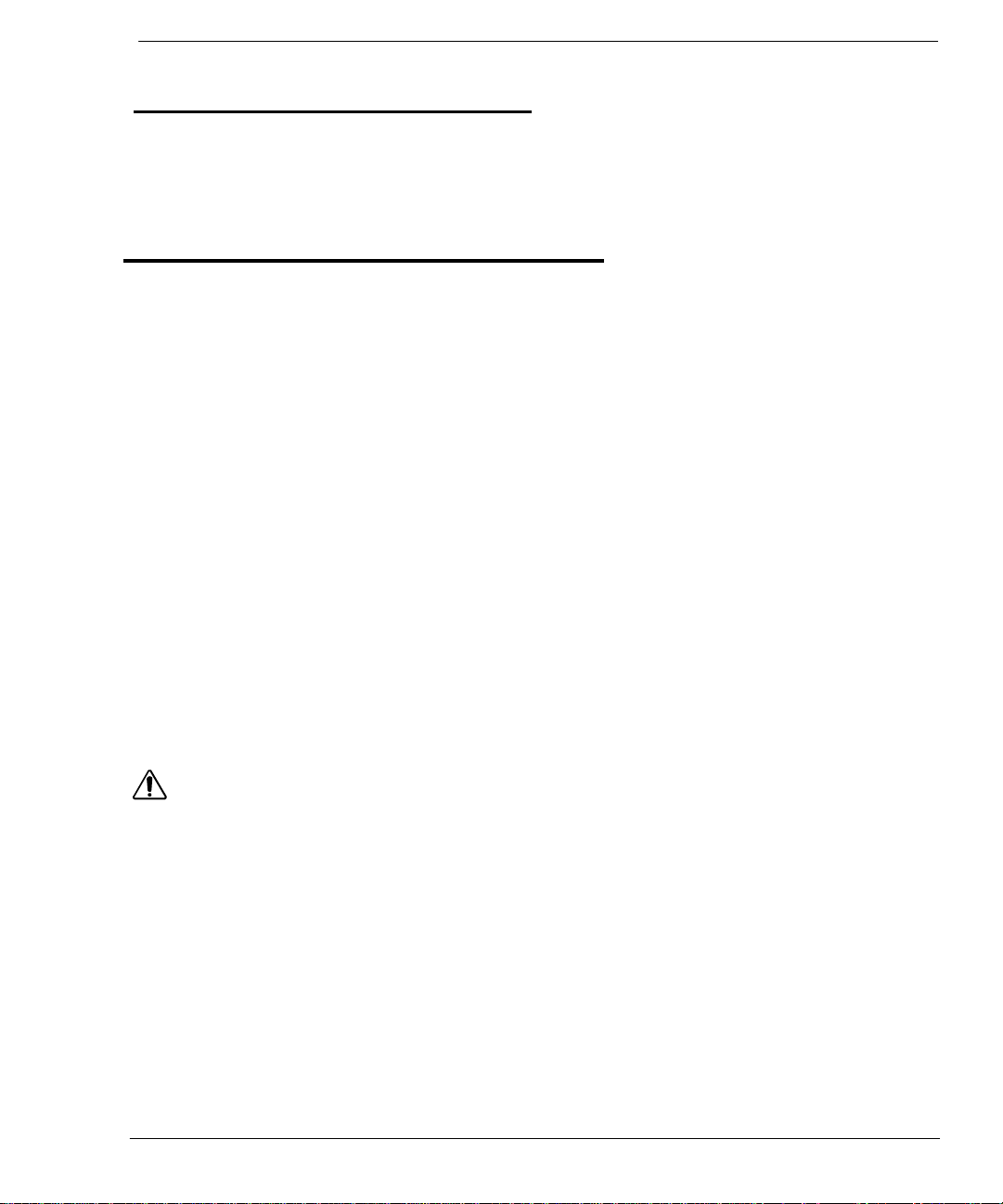
AED PRO PARTS
The following drawings show the AED Pro parts and their locations.
Battery Compartment
RescueReady
Status Indicato
(push in to open)
MANUAL OVERRIDE Button
Behind cover)
IR Port
Latch
Lid
Electrode Expiration
Window
Pad/Electrode Holders
Speaker
Pad/Electrode Socket
Shock Button
Color Display
THE AED PRO HAS THREE MODES:
Operating Mode: Defined as having the battery installed and the lid open. This is the mode the AED Pro would be in
during an actual rescue situation.
Standby Mode: When the battery is installed, but the lid is closed. In this mode the AED Pro is not being used in a
rescue. The device will conduct its routine self-tests to ensure proper operation.
Storage Mode: When the battery is removed, such as during shipping or transport. With the battery removed, the AED
Pro is unable to perform self-tests or rescues.
Page 12 of 53 Copyright © 2007, General Electric Company 2023486-201 Rev C
Page 14
INTELLISENSE® BATTERY
Section 2: Getting Started
ABOUT THE INTELLISENSE® BATTERY
• When the last battery indicator (LED) is red, the battery is low. Replace the battery right away.
• A new battery typically takes 10 seconds to charge the AED Pro to maximum energy.
• AED Pro batteries will provide up to 290 shocks
• Output voltage: 12VDC (max)
• Batteries are non-rechargeable
• Lithium contents: 9.2g (max)
MODEL TYPICAL SHOCKS
2023681 (9145) Lithium Up to 290
• Check local regulations for disposal information
BATTERY SHELF LIFE
The Responder AED Pro batteries have a shelf life of five years. Shelf life is defined as the length of time a battery can
be stored, prior to installation into AED Pro, without degrading its performance.
Note: Storing the battery outside its specific range (0-50°C)(30-122°F) will decrease battery life.
WARNING: Lithium Sulfur Dioxide Battery 2023681-001 (9145) is Not Rechargeable
Do not attempt to recharge the battery. Any attempt to recharge the battery may result in an explosion or fire
hazard.
CAUTION: Lithium Sulfur Dioxide Battery
Pressurized contents: Never recharge, short circuit, puncture, deform, or expose to temperatures above 65°C
(149°F). Remove the battery when discharged.
CAUTION: Battery Disposal
Recycle or dispose of the lithium battery in accordance with all federal, state and local laws. To avoid fire and
explosion hazard, do not burn or incinerate the battery.
CAUTION: Use only Manufacturer Approved Equipment
Using batteries, pads, cables, or optional equipment other than those approved by General Electric may cause
the Responder AED Pro to function improperly during a rescue.
2023486-201 Rev C © 2007 General Electric Company Page 13 of 53
Page 15
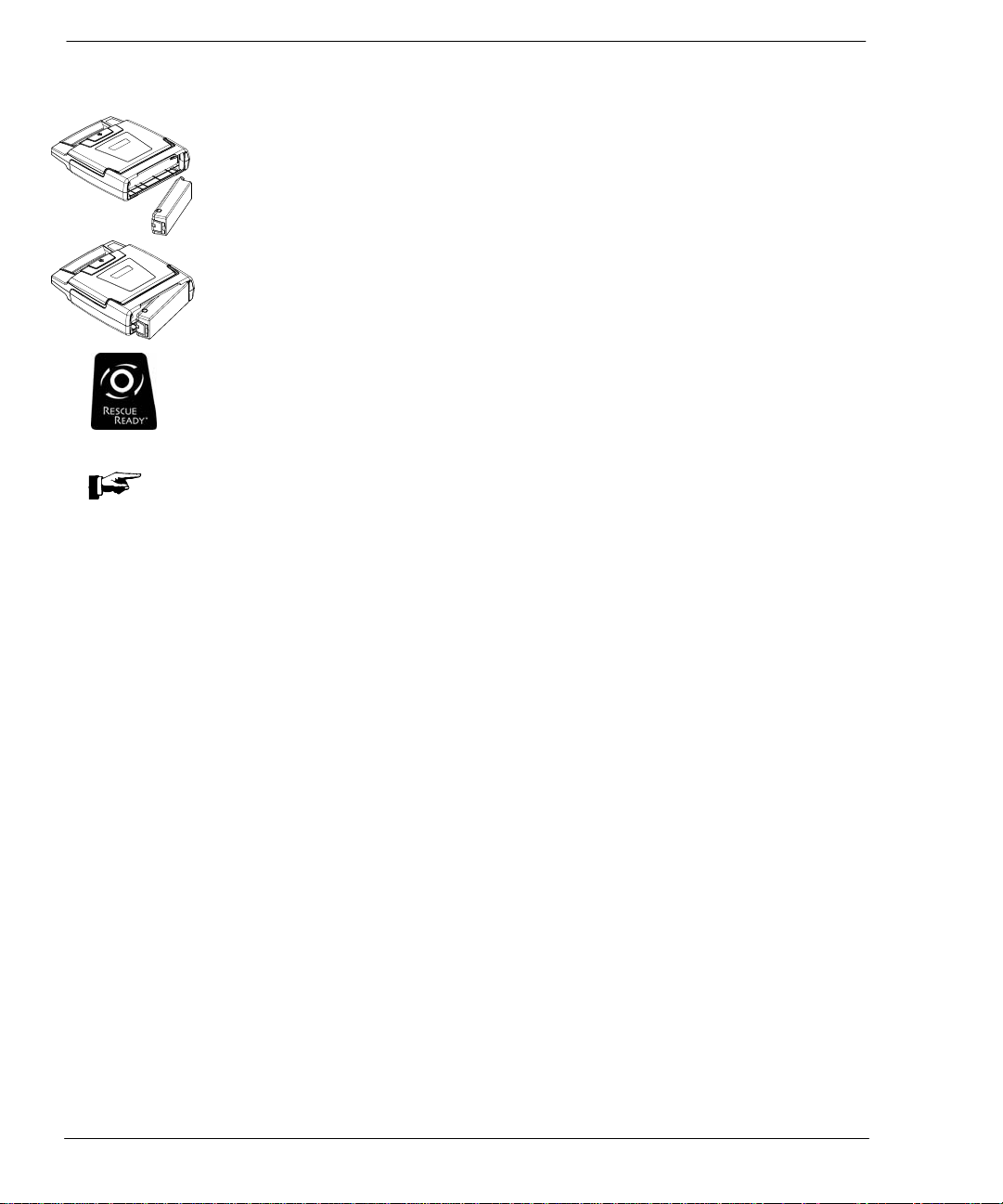
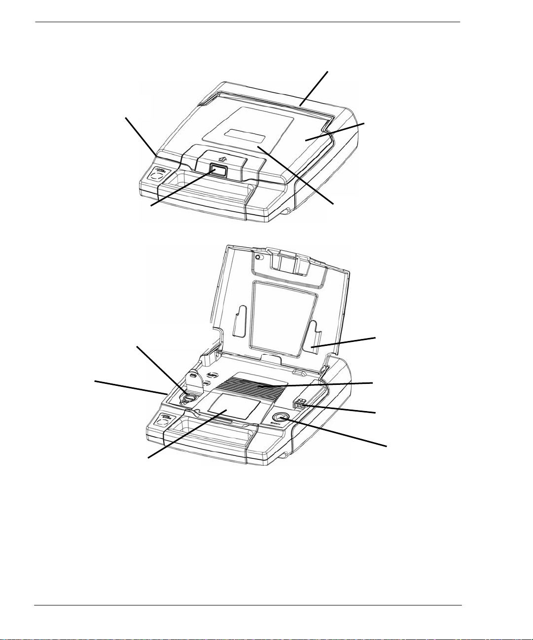
BATTERY INSTALLATION
Note: Batteries with part number 2023489-001 (9144) and 2023681-001 (9145) are for use only with
Responder AED Pro and should not be used with other AEDs.
1. With the label on the battery facing the AED Pro battery compartment, insert the battery as
shown in the drawing.
2. Push the latched end of the battery firmly into the AED Pro, as shown in the drawing, until the
battery snaps into place. The exposed side of the battery should be flush with the outside of the
AED Pro case.
3. Open the lid for 5 seconds to initiate self-test. If the battery is installed properly, the STATUS
INDICATOR will turn GREEN. Close the lid.
Page 14 of 53 Copyright © 2007, General Electric Company 2023486-201 Rev C
Page 16
Section 2: Getting Started
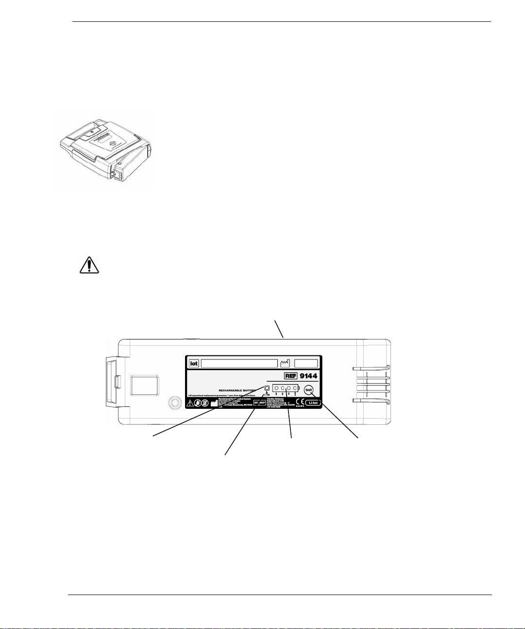
RECHARGEABLE BATTERY
The rechargeable battery (P/N 2023489-001) and charger (P/N 2023490-001) are separately sold accessories for the
Responder AED Pro.
DIRECTIONS FOR USE:
• Remove the rechargeable battery from the Responder AED Pro; the rechargeable
battery can only be recharged when removed from the Responder AED Pro.
• Plug the charger into an appropriate electrical outlet.
• Insert the charger cable into the rechargeable battery and ensure the yellow LED
above the rechargeable battery symbol is on. Charging is complete when the yellow
Charge LED goes out, and the four green Fuel Gauge LEDs are continuously lit.
• Remove the charger cable from the battery when done charging. Charging may be
terminated early by removing the charger cable from the battery. If the battery is
charged for a minimum of 3 hours, the stated capacities will be met.
If the yellow Charge LED blinks continuously, a charging error has occurred. Contact customer
service in the event of a charging error.
Insert Charger Here
Rechargeable with LED
Battery Capacity
Test Button
Rechargeable Battery
(Also located on back)
2023486-201 Rev C © 2007 General Electric Company Page 15 of 53
Page 17
DEFIBRILLATION ELECTRODES (PADS)
The defibrillation pads come in a ready-to-use, sealed package containing one pair of
self-adhesive pads with an attached cable and connector. The pads are disposable
and should be discarded after each rescue. The pads have a limited shelf life and
shall not be used beyond the expiration date. Keep a fresh, unopened pair of pads
plugged into the AED Pro at all times. Refer to the pads package label for operation
temperatures.
An audible and visual alert will indicate after the self-test if the pads are missing, unplugged or damaged.
CAUTION: Damaged or Expired Pads
Using pads that are damaged or expired may result in improper AED Pro performance.
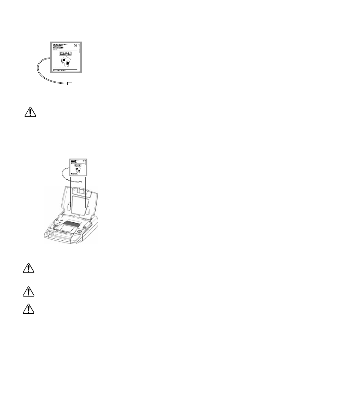
PAD INSTALLATION
1. Open the lid of the AED Pro.
2. Place the pad package into the lid so that the expiration label is visible
through the clear window on the lid. The expiration date of the pads will
CAUTION: Use only Approved Equipment
Using batteries, defibrillation pads, cables, or optional equipment other than those approved by
General Electric may cause the AED Pro to function improperly during a rescue.
CAUTION: Possible Improper AED Pro Performance
Using defibrillation pads that are damaged or expired may result in improper AED Pro performance.
CAUTION: Both polarized and non-polarized defibrillation pads are available for Responder AED Pro. If using
polarized pads, always place sternum and apex pads as shown on the packaging. Non-polarized
pads may be placed in either position for a rescue; however, the ECG waveform will be correctly displayed in only
one position. To correctly display an inverted ECG, simply reverse the defibrillation pads.
then be readable without opening the lid of the AED Pro.
3. Match the color of the connectors (red to red), slightly lift the tab of the
pad socket then plug the pad connector into the AED Pro case as shown
in the drawing.
4. Tuck the excess cable length in the bottom holder as shown in the
drawing. With the pad package completely secured to the AED Pro lid,
close the lid.
5. Make sure the expiration date is visible through the clear window of the
lid.
6. Make sure that the STATUS INDICATOR is GREEN.
DIRECTIONS FOR USE:
1. Do NOT open until ready to use, short term use only.
2. Ensure the skin site is clean and dry.
3. Separate one pad from liner.
4. Place one pad on skin.
5. Peel and place remaining pad.
Page 16 of 53 Copyright © 2007, General Electric Company 2023486-201 Rev C
Page 18

Section 2: Getting Started
AED PRO INDICATORS
The following indicators are located on the AED Pro.
RESCUEREADY® STATUS INDICATOR
When the STATUS INDICATOR is RED, maintenance is required.
AUDIBLE MAINTENANCE INDICATOR
When the daily, weekly or monthly self-test determines service is required, an audible beep is sounded every 30 seconds
until the lid is opened or the battery power is depleted. Opening and closing the lid may deactivate the beep. If the next
automatic self-test does not correct the error, the beep will be reactivated.
The STATUS INDICATOR is located on the Responder AED Pro handle. When this indicator is
GREEN, the device is RescueReady. This means the AED Pro self-tests have verified the following:
• Battery has an adequate charge.
• Pads are properly connected to the AED Pro and in working order.
• Integrity of the internal circuitry is good.
Note: When Status Indicator is RED or Service Indicator is illuminated, device cannot be
used to perform a rescue.
DIAGNOSTIC PANEL
A B C D
K
E
H
A. SMARTGAUGE BATTERY Indicator
This indicator displays the battery capacity. At maximum charge, the battery is GREEN. With use, the
GREEN level will gradually go out from right to left as the battery capacity decreases. Once the battery
level is depleted, the battery indicator will turn to RED and flash, and the battery should be replaced.
Note: When the battery indicator is RED, upon lid opening or at any time during the rescue
– a “BATTERY LOW” prompt will be issued at once. However, the AED Pro is capable of delivering at
least nine more defibrillation shocks after the first time a “BATTERY LOW” prompt is issued.
2023486-201 Rev C © 2007 General Electric Company Page 17 of 53
G
F, J I
Page 19

B. NUMBER OF SHOCKS DELIVERED Indicator
This indicator counts and displays the number of shocks delivered.
C. ELAPSED RESCUE TIME Indicator
This indicator times and displays the elapsed rescue time.
D. HEART RATE Indicator
This indicator displays the patient’s heart rate.
E. ECG Display
Four and a half seconds of the patient’s ECG is displayed.
F. PAD PLACEMENT Display
Visually assists the operator with pad placement with the directions for use. Appropriate text
prompts are also displayed.
G. TEXT Display
The text display has 2 lines of text. It provides the operator with information regarding system
initialization, text version of the voice prompts and data during a rescue, and diagnostics.
System initialization occurs when the lid is first opened. The text display shows the operator the
identifiers for the internal code, voice prompts and text prompts versions.
H. CPR Counter
During CPR, a countdown timer will be displayed.
I. SERVICE Indicator
When displayed, indicates that service is required that can only be performed by qualified service
personnel.
J. PAD Indicator
The pad indicator will flash with a voice and text prompt indication “Check Pads” when one of the following
occurs:
• Pads are not properly connected to the AED Pro
• Pads are not within operational specifications (cold, dried, damaged)
• Pads are not connected properly to the patient during the rescue.
K. Z-BAR Indicator
The Z-Bar provides a relative visual graphical indicator of the total transthoracic impedance between the two
defibrillation pads. The Z-Bar is used in the assessment of:
• Adequate pad placement
• Pad quality and integrity
• Pad adhesion to the patient’s skin
• Proper pad connection to the AED Pro
• Provides for quick assessment between pad off and pads shorted
Note: There is a 3 second delay between the time the AED Pro lid is opened and the start of the
rescue (when the lid was first opened).
Note: When Status Indicator is RED or Service Indicator is illuminated, device cannot be
used to perform a rescue.
Page 18 of 53 Copyright © 2007, General Electric Company 2023486-201 Rev C
Page 20

Section 2: Getting Started
CONTROL BUTTONS
The AED Pro has two buttons.
SHOCK BUTTON
MANUAL OVERRIDE BUTTON
MANUAL OVERRIDE
The SHOCK button is located at the far right of the control panel and serves as an indicator to
notify the user that the unit is ready to shock and as a button to deliver the shock.
The word SHOCK and the shock button will illuminate RED when the AED Pro is ready to deliver a
defibrillation shock to the patient.
The MANUAL OVERRIDE button is located at the far left of the control panel and converts the
device from automated mode to manual. This feature should only be used by medical professionals
trained in manual defibrillation.
• Lift the cover to access the button.
• Converts to manual standby mode when pushed once, a voice prompt “Press Manual Button Again
to Confirm”, will be heard. Converts to manual mode when MANUAL button is pressed again.
• If the rescuer does not confirm within 30 seconds of the capacitors charging, the AED will revert
back to AED Mode.
• If the Medical Director has disabled this feature in MDLink, an icon indicating No MANUAL MODE
will appear in the bottom left of the display
SETTING THE AED PRO INTERNAL CLOCK
The internal clock is preset at Central Standard Time and should be reset to the correct date and local time. The AED Pro
will automatically adjust itself for daylight savings time. This feature can be turned off using the ServiceLink software. To
set the clock, you will need a PC with Windows 95 or later operating system, RescueLink software installed, an IR port on
the PC, and an IR adapter as specified below.
To set the clock settings:
• Open the lid and remove pads from the pads socket.
• Ensure that the PC is set at the correct local time and date.
• Point IR port on the AED Pro to IR eye on the PC and select G3 Pro.
• Run the RescueLink software on the PC.
• Verify that the voice prompt states “Communications Mode”.
• Click Communications on the main menu. Select AED Pro Date and Time.
• Click on the Get button to review the current time in the AED Pro.
• If the time and date is incorrect, click Set to set new time and date. The AED Pro date and time will
automatically be updated to the PC’s time and date.
• Reinstall pads per instructions on page 18.
• Close the lid.
Note: The IR port on the AED Pro is designed to work with IR adapter ACT-IR220LN115 from ACTiSys
Corp. on Windows based PCs only. Please contact customer service to order, P/N 162-0108-001. Other IR
products may interfere with the transmission and are not for use with the AED Pro.
2023486-201 Rev C © 2007 General Electric Company Page 19 of 53
Page 21

VOICE PROMPTS AND TEXT DISPLAY
The voice prompts activate when the AED Pro lid is opened and help guide the operator through the rescue. The
Responder AED Pro text display provides a visual display of most of the audible voice prompts.
The following table lists the voice and text prompts and a description of when the prompts are issued.
VOICE PROMPT TEXT DISPLAY SITUATION
“Tear Open Package and Remove
Pads.”
“Peel One Pad from
Plastic Liner.”
“Place One Pad on Bare Upper
Chest.”
“Peel Second Pad and
Place on Bare Lower Chest as
Shown.”
“Press Pads Firmly to Patient’s Bare
Skin.”
“Do Not Touch Patient! Analyzing
Rhythm.”
“Shock Advised.”
“Charging.”
“Stand Clear! Push
Flashing Button to
Deliver Shock.”
“Plug in Pads Connector”
“Shock Delivered”
“It is now safe to touch the patient”
Start CPR
Give 30 compressions
Then Give Two Breaths
TEAR OPEN PACKAGE
REMOVE PADS
PEEL ONE PAD
FROM PLASTIC LINER
PLACE ONE PAD ON
BARE UPPER CHEST
PEEL SECOND PAD
PLACE ON LOWER CHEST
PRESS PADS TO
PATIENT’S BARE SKIN
DO NOT TOUCH PATIENT
ANALYZING RHYTHM
SHOCK ADVISED
CHARGING
STAND CLEAR
PUSH BUTTON TO SHOCK
PLUG IN PADS
CONNECTOR
SHOCK DELIVERED
NOW SAFE TO TOUCH THE
PATIENT
START CPR
30 COMPRESSIONS
2 BREATHS
When the lid is opened, this phrase is
repeated twice to initiate the rescue
sequence.
Prompt repeats until one pad is peeled off of
the liner.
Prompt repeats twice while one pad is placed.
Prompt repeats until both pads are placed on
the patient.
Prompt issued when better connectivity is
required because impedance is too high.
Prompt issued when the AED Pro is analyzing
the cardiac rhythm of the patient.
Prompts issued when the AED Pro is
preparing to deliver a defibrillation shock.
Prompt repeats while AED Pro is charging.
Prompt issued after the AED Pro is fully
charged and ready to deliver the defibrillation
shock. The RED Shock indicator flashes and
the phrase repeats for 30 seconds or until the
Shock button is pushed.
Prompt issued when the pad socket does not
have defibrillation pads or ECG electrodes
connected.
After the AED delivers a defibrillation shock
Advises the rescuer when it is safe to touch
the patient.
After the AED delivers a defibrillation shock.
After the AED detaches a non-shockable
rhythm.
Perform CPR for 2 minutes
Page 20 of 53 Copyright © 2007, General Electric Company 2023486-201 Rev C
Page 22

Section 2: Getting Started
(VOICE PROMPT AND TEXT DISPLAY CONTINUED)
VOICE PROMPT TEXT DISPLAY SITUATION
“Check Pads”
“Battery Low”
“Analysis Interrupted. Stop Patient
Motion.”
“Open Lid to Continue Rescue”
“Rhythm Changed.
Shock Cancelled.”
“ECG Monitoring Mode”
“Communications Mode”
(Beep)
“Continue CPR”
“Service Required”
CHECK PADS
BATTERY LOW
ANALYSIS INTERRUPTED
STOP PATIENT MOTION
OPEN LID TO
CONTINUE RESCUE
RHYTHM CHANGED
SHOCK CANCELLED
ECG MONITORING MODE
COMMUNICATIONS MODE
(None)
CONTINUE CPR
SERVICE REQUIRED
Prompt issued when patient
impedance is too low or the pads are
shorted.
Prompt issued once when the battery
voltage becomes low, although a
rescue can continue for approximately
9 more shocks. When the battery is
too low to do a rescue, the phrase
repeats continuously. You must
replace the battery before continuing
with the rescue. If completely
depleted, all AED Pro activity will
terminate.
Prompt issued when the AED Pro
detects ECG noise artifact, stop
moving or touching the patient.
Prompt issued when the lid is
inadvertently closed during a rescue,
this prompt will repeat for 15 seconds.
Prompt issued when the device is
prepared to shock then detects a
change in rhythm and therefore
cancels the shock.
Prompt issued when ECG Patient
Cable is inserted into the pad socket.
Prompt issued when the lid is open
and IR is transmitting the AED Pro.
One “Beep” occurs in 30-second
intervals during CPR when enabled by
the ServiceLink software program,
also occurs when the AED Pro
requires maintenance.
Prompt issued during CPR mode
when enabled, or when a rescue is
resumed in CPR mode after being
interrupted by the lid closing.
Prompt issued after the self-tests
determine that the AED Pro is not
functioning properly. The prompt
“Service Required” will be heard when
the lid is opened. The red Service
indicator will illuminate and “Service
Required” will repeat until you close
the lid. After closing the lid, an alarm
beep will be heard until the battery is
removed or becomes completely
depleted.
2023486-201 Rev C © 2007 General Electric Company Page 21 of 53
Page 23

ADVANCED FEATURE PROMPTS
VOICE PROMPT
“Entering Manual Mode. Press Button
Again to Confirm”
“Manual Mode. Charging”
“Manual Mode Not
Confirmed.”
“If Rhythm is Shockable, Press
SHOCK Button to Deliver Therapy.”
“Shockable Rhythm. Attach
Defibrillation Pads.”
“Device Will Disarm in :30”
TEXT DISPLAY SITUATION
MANUAL MODE
PRESS BUTTON TO CONFIRM
MANUAL MODE
CHARGING
MANUAL MODE
NOT CONFIRMED
IF SHOCKABLE RHYTHM
PRESS SHOCK BUTTON
SHOCKABLE RHYTHM
ATTACH DEFIBRILLATION PADS
DEVICE WILL DISARM IN :30
Prompt issued after ALS presses the
MANUAL button once to initiate the
manual mode.
Prompt issued after ALS presses the
MANUAL button again to confirm.
Prompt issued when the MANUAL
button is not pressed a second time
within five seconds, the device stays
in AED Pro mode.
Prompt issued when in manual mode,
prompts ALS personnel to press
SHOCK button if ECG indicates a
shockable rhythm.
Prompt issued when the device is
performing ongoing ECG monitoring
via the ECG Patient Cable Kit and
detects a shockable rhythm.
Should the rescuer go into manual
mode and decide that AED mode is
more appropriate, the AED Pro will
revert back to AED mode 30 seconds
after charging is complete. The
seconds will count down from 30
on the display.
When "Remain in manual mode" has
been enabled (Using ServiceLink
software). The AED will disarm but
remain in Manual Mode. See page 27
Page 22 of 53 Copyright © 2007, General Electric Company 2023486-201 Rev C
Page 24

Section 3: Performing a Rescue
SECTION 3: PERFORMING A RESCUE
OVERVIEW
The AED Pro is designed for ease of data management and review. The data stored in internal memory can be displayed
on the PC screen using the RescueLink software.
TOPIC
OPERATING MODES 23
HOW TO PERFORM A RESCUE 24
USING MANUAL OVERRIDE 27
Z-BAR INDICATOR 29
WARNINGS 30
OPERATING MODES
The AED Pro comes in three operating models. The AED Pro is pre-set to AED mode, but the user can change the mode
during each unique rescue. The energy delivered is determined by the Medical Director and programmed into the AED
Pro prior to the rescue.
PAGE #
AED MODE (default)
For patients exhibiting signs of sudden cardiac arrest. Once defibrillation pads are placed on the patient, the AED Pro
analyzes the heart rhythm. If a shockable rhythm is detected, the AED Pro automatically charges to a pre-set energy level
and prompts rescuer to push the SHOCK button to deliver therapy.
MANUAL MODE
For patients exhibiting signs of sudden cardiac arrest. Once the defibrillation pads are placed on the patient,
a trained ALS rescuer may wish to read the ECG display to determine whether or not a shock is required.
This mode is activated by pushing the manual button once then again to confirm; the device will begin charging. If the
rescuer deems that the rhythm is shockable, therapy can be delivered by pressing the SHOCK button. Then, the AED Pro
reverts back to AED mode. By entering this mode, the rescuer is taking responsibility to identify a shockable rhythm and
to administer a shock. Should the rescuer go into manual mode and decide that AED mode is more appropriate, the AED
Pro will revert back to AED mode 30 seconds after charging is complete. The seconds will count down on the display. If
the Medical Director has disabled this feature in ServiceLink, an icon indicating NO MANUAL MODE will appear in the
bottom left of the display. With Manual Mode enabled and the Medical Director has also enabled "REMAIN IN MANUAL
MODE" the AED will not revert to the AED or CPR mode, but will remain in Manual mode
ECG DISPLAY MODE
For patients who are conscious and breathing for longer term ECG monitoring. ECG display fur use in determining gross
morphology can be activated by inserting the ECG patient monitoring cable into the electrode socket on the AED Pro,
connecting the 3-lead patient cables to the specialized ECG electrodes and placing as directed onto the patient. Should
the AED Pro detect a shockable rhythm, defibrillation pads should be placed on the patient, the ECG patient monitoring
cable removed from the electrode socket on the AED Pro and the connector should be plugged into the pad socket to
enable a defibrillation shock.
2023486-201 Rev C © 2007 General Electric Company Page 23 of 53
Page 25

HOW TO PERFORM A RESCUE
STEP 1: ASSESSMENT AND PAD PLACEMENT
PREPARATION
Determine that the patient is over 8 years of age or weighs more than 55 pounds (25 kg) and exhibits
the following:
Perform CPR until AED is attached to patient.
Remove clothing from the patient’s chest. Ensure the skin site is clean and dry. Dry the patient’s chest and shave
excessive hair if necessary.
Open the AED lid and follow prompts.
PLACE PADS
The AED will issue the prompt “Tear Open Package and Remove Pads.” Keep the pads connected to the AED,
tear the package along the dotted line and remove the pads from the package. Leave the package attached to the pad
wires.
When the pads are placed, the voice prompt will say “Do not touch patient. Analyzing Rhythm.” If the pads are not
properly placed or become disconnected at any time during the rescue, the voice prompt “Check Pads” will be heard.
When this occurs, ensure that:
Pads are firmly placed on clean, dry skin
Pads cable is securely plugged into the AED
The patient is unresponsive, and
The patient is not breathing.
Warning: When the patient is a child under 8 years of age or weighs less than 55 lbs (25kg), the AED should
be used with the Model 2019199-003 Pediatric Attenuated Defibrillation Electrodes. Therapy should not be
delayed to determine the patient’s exact age or weight. See the directions for use accompanying pediatric
electrodes for procedure on changing adult pads to pediatric.
Note: When Status Indicator is RED or Service Indicator is illuminated, device cannot be used to perform a
rescue.
After the prompt “Peel One Pad From Plastic Liner,” with a firm, steady pull, carefully
peel one pad away from the release liner.
Then, after the prompt “Place One Pad on Bare Upper Chest,” place the pad with the
sticky side of on the patient’s skin on the upper right chest, placing the top of the pad
on the collarbone. Avoid placing the pad directly over the sternum.
Finally, after the prompt “Peel Second Pad and Place on Bare Lower Chest
As Shown,” pull the second pad from the release liner and place it on the lower left
chest, below and left of the breast.
Note: The standard defibrillation pads are non-polarized and can be placed in either position as
shown on the pad package. When using pacing or monitoring pads, refer to placement instructions on
the pacing or monitoring pad package.
Page 24 of 53 Copyright © 2007, General Electric Company 2023486-201 Rev C
Page 26

Section 3: Performing a Rescue
STEP 2: ECG ANALYSIS (AED MODE)
As soon as the AED detects proper pad placement, the voice prompt “Do not touch patient. Analyzing Rhythm.” will be
heard. The AED will begin to analyze the cardiac rhythm of the patient.
When the AED is charged, it continues to analyze the patient’s heart rhythm. If the rhythm changes and a shock is no
longer needed, the AED will issue the prompt “Rhythm Changed. Shock Cancelled,” disarm and enter CPR mode.
If noise is detected during analysis, the AED will warn you with the prompt “Analysis Interrupted. Stop Patient Motion” and
restart the analysis. This usually occurs if the patient is excessively jostled or there is a strong electromagnetic emitting
electronic device nearby (within 2 meters). Remove the electronic device or stop the excessive motion when you hear this
prompt.
If a shock is advised, the voice prompt will say, “Shock Advised. Charging.” When the AED is
ready to deliver a defibrillation shock, the Shock button will flash and the prompt, “Stand Clear.
Push Flashing Button to Deliver Shock” will be heard. The tone, flashing button, and voice
prompt will continue until the shock is delivered or change in rhythm is detected, or 30 seconds
elapse.
STEP 3: SHOCK DELIVERY AND CPR MODE (AED MODE)
When the AED is ready to deliver a defibrillation shock, the Shock button will flash and the prompt “Stand Clear. Push
Flashing Button to Deliver Shock” will be heard.
After the AED delivers the first defibrillation shock, the voice prompt will say “Shock Delivered.” The AED will then prompt
you to start CPR.
Note: During a rescue, the screen displays voice prompts, elapsed time of rescue and number of shocks
delivered.
Make sure no one is touching the patient and push the Shock button to deliver a defibrillation
shock. If you do not push the Shock button within 30 seconds of hearing the prompt, the AED will
disarm and enter CPR mode.
2023486-201 Rev C © 2007 General Electric Company Page 25 of 53
Page 27

CPR MODE
During the CPR time-out period, the AED will not interrupt the CPR mode. After the CPR time-out period has expired, the
voice prompt “Do Not Touch Patient. Analyzing Rhythm.” will be heard.
Note: During CPR mode, a countdown timer is displayed.
If the patient is conscious and breathing normally, leave the pads on the patient’s chest connected to the AED. Make the
patient as comfortable as possible and wait for Advanced Life Support [ALS] personnel to arrive. Continue to follow the
voice prompts until the ALS personnel arrive, or proceed as recommended by the Medical Director.
After shock delivery or detection of a non-shockable rhythm, the AED automatically enters CPR
mode. The voice prompt will say, “It is now safe to touch the patient. Start CPR.”
STEP 4: POST RESCUE
After transferring the patient to ALS personnel, prepare the AED for the next rescue:
1. Retrieve the rescue data stored in the internal memory of the AED by using
RescueLink software installed on a PC (see detailed procedure in the Data
Management section).
2. Connect a new pair of pads to the AED.
3. Close the lid.
4. Verify that the Status Indicator on the AED handle is GREEN.
Page 26 of 53 Copyright © 2007, General Electric Company 2023486-201 Rev C
Page 28

Section 3: Performing a Rescue
USING MANUAL OVERRIDE (manual mode)
For use by qualified ALS personnel only. The AED Pro has a manual override feature which overrides the AED Pro’s
automatic analysis protocol. By entering this mode, the rescuer is taking responsibility to identify a shockable rhythm and
to administer a shock. The default setting for the manual override is "enabled". When enabled, the Manual Override
option allows the user to charge the AED and deliver a shock at the user's discretion. After the shock button is pushed or
30 seconds has elapsed, the device will automatically exit the manual mode and return to the AED mode.
Optionally, the manual override default behavior may be modified so that after entering manual mode, the AED will remain
in the manual override mode for the duration of the rescue. This feature is enabled by selecting the "REMAIN IN MANUAL
MODE" option in the ServiceLink software and can be configured during the initial set up of the AED.
STEP 1: Please refer to: “STEP 1: ASSESSMENT AND PAD PLACEMENT” on page 24.
STEP 2: Lift plastic cover on far left of diagnostic panel.
STEP 3: Push the MANUAL button once to initiate. The voice prompt and corresponding text prompts will
indicate “Entering manual mode. Press button again to confirm.”
STEP 4: The MANUAL button must be pushed again to confirm and convert to manual mode. The manual indicator on
STEP 5: The voice prompts and corresponding text prompts will indicate, “If rhythm is shockable, press SHOCK button
the display panel will be active. The voice and corresponding text prompts will indicate, “Manual Mode.”
Note: The manual mode is initially displayed on the screen when activated. If the Medical Director has
disabled this feature in ServiceLink, an icon indicating NO MANUAL MODE will appear in the bottom left
of the display. Continue the rescue in AED Mode.
to deliver therapy”. Read the ECG and determine if the rhythm is shockable. If so, press the SHOCK button to
delivery therapy.
Note: The RHYTHMx analysis algorithm is disabled in manual mode. It is the rescuer’s responsibility to
determine if a shock is necessary
STEP 6: The AED Pro will revert to AED / CPR MODE once a shock is delivered. Follow the voice prompts.
STEP 7: To re-enter manual mode, press the MANUAL button ONCE.
If "Remain in Manual Mode" has been enabled, the device will remain in Manual Mode.
Note: Should the rescuer go into manual mode and decide that AED mode is more appropriate, the AED Pro
will revert back to AED mode 30 seconds after charging is complete. The seconds will count down on
the display. If "Remain in Manual Mode" has been enabled, the device will remain in Manual Mode.
EXITING MANUAL MODE
Default: The device will return to AED mode after:
• Pushing the shock button
• 30 seconds has elapsed without pushing the shock button
• Closing the AED lid momentarily
• Removing the battery momentarily
• Attaching the optional 3-lead ECG monitoring cable
• Disconnecting the pads from the AED
• Removing the pads from the patient
EXITING MANUAL MODE WHEN "REMAIN IN MANUAL MODE" HAS BEEN ENABLED
• Closing the AED lid momentarily
• Removing the battery momentarily
• Attaching the optional 3-lead ECG monitoring cable (upon reattaching the defibrillation pads the AED will be in
manual mode).
2023486-201 Rev C © 2007 General Electric Company Page 27 of 53
Page 29

ECG DISPLAY USING SEPARATE ECG LEAD WIRES (ECG DISPLAY MODE)
The AED Pro can be used for ongoing display of ECG for attended monitoring of gross morphology. This feature requires
a separately sold ECG Patient Cable Kit. It is not necessary to turn the device off prior to connecting the ECG cable.
While the ECG cable is connected to the AED Pro, the shock capability is disabled.
Indications for use:
A conscious or breathing patient, regardless of age.
Contraindications:
No known contraindications.
The separately sold ECG Patient Cable Kit is required to use this feature. The Kit is designed for connection to ECG
electrodes per AAMI or IEC color convention. Once connected the AED Pro displays and evaluates the patient’s ECG
(Lead II). Follow all prompts from the AED Pro.
The kit includes a device connector, which contains electronics (with a non-replaceable battery) that is inserted into the
pad port on the AED Pro, a trunk cable terminating in a molded yoke and three patient leadwires permanently attached to
the yoke. Each leadwire terminates in an electrode connector to attach to a disposable pad
CAUTION: Not a Patient Monitor
The AED Pro is not a true patient monitor with the requisite alarms. Medical personnel should attend
patients at all times while the AED Pro is in use.
Page 28 of 53 Copyright © 2007, General Electric Company 2023486-201 Rev C
Page 30

Section 3: Performing a Rescue
Z-BAR™ INDICATOR
The Z-Bar provides a relative visual graphical indicator of the total transthoracic impedance between the two defibrillation
pads. The Z-Bar is used in the assessment of:
• Adequate Pad placement
• Pad quality and integrity
• Pad adhesion to the patient’s skin
• Proper Pad connection to the AED Pro
• Provides for quick assessment between PADS OFF and PADS SHORTED
The Z-Bar is divided into 5 sections. The ideal operating range is Section 3 (impedance range from 30 to <150).
Z-BAR
SECTION MEASURED IMPEDANCE
1
2 >20 but < 30Ω Lower marginal operating range. Indicates
3 >30 but < 150Ω Normal operating range Green
Note: The Z-Bar is displayed on all therapy screens with the exception of the ECG MONITORING screen. On
the ECG MONITORING screen the Z-Bar will be displayed only if the detection lead is set to Pads.
DESCRIPTION COLOR FILL
RANGE (OHMS)
<20Ω Lower Limit Alarm – Non operational range Red
Yellow
potential Pad degradation in Pad quality or
position
4 >150 but <180Ω Upper marginal operating range. Indicates
5 >180Ω Upper Limit Alarm – Non operational range Red
1 2 3 4 5
potential Pad degradation in Pad quality or
position
Yellow
2023486-201 Rev C © 2007 General Electric Company Page 29 of 53
Page 31

WARNINGS
The following cautions must be observed to prevent problems during the rescue.
DANGER: Fire and Explosion Hazard
Do not use in the presence of flammable gases (including concentrated oxygen) to avoid possible explosion or fire
hazard.
WARNING: Shock Hazard
Defibrillation shock current flowing through unwanted pathways is potentially a serious electrical shock hazard. To
avoid this hazard during defibrillation abide by all of the following:
• Do not touch the patient, unless performance of CPR is indicated
• Do not touch metal objects in contact with the patient
• Do not use in water
• Keep defibrillation pads and ECG electrodes clear of other pads or metal parts in contact with
• Disconnect all non-defibrillator proof equipment from the patient before defibrillation
WARNING: Shock and Possible Equipment Damage
Disconnect all non-defibrillator proof equipment from the patient before defibrillation to prevent electrical shock and
potential damage to the equipment.
CAUTION: Use only Approved Equipment
Using batteries, pads, cables, or optional equipment other than those approved by General Electric may cause the
AED Pro to function improperly during a rescue.
CAUTION: Possible Improper AED Pro Performance
Using pads that are damaged or expired may result in improper AED Pro performance.
CAUTION: Possible Radio Frequency (RF) Susceptibility
RF susceptibility from cellular phones, CB radios and FM 2-way radio may cause incorrect rhythm recognition and
subsequent shock advisory. When attempting a rescue using the AED Pro, do not operate wireless
radiotelephones within 2 meters of the AED Pro – turn power OFF to the radiotelephone and other like equipment
near the incident.
CAUTION: Possible Interference with Implanted Pacemaker
Therapy should not be delayed for patients with implanted pacemakers and a defibrillation attempt should be made
if the patient is unconscious and not breathing. The AED Pro has pacemaker detection and rejection, however with
some pacemakers the AED Pro may not advise a defibrillation shock.
Placing Pads:
• Do not place the pads directly over an implanted device.
• Place the pad at least on inch from any implanted device.
CAUTION: Moving the Patient During a Rescue
During a rescue attempt, excessive jostling or moving of the patient may cause the AED Pros to improperly
analyze the patient’s cardiac rhythm. Stop all motion or vibration before attempting a rescue.
patient
Page 30 of 53 Copyright © 2007, General Electric Company 2023486-201 Rev C
Page 32

Section 4: Data Management
SECTION 4: DATA MANAGEMENT
OVERVIEW
The Responder AED Pro is designed for ease of data management and review. The data stored in internal memory can
be displayed on the PC screen using the RescueLink software.
TOPIC
RECORDING THE RESCUE DATA 31
REVIEW THE RESCUE DATA 31
RESCUELINK OVERVIEW 32
RESCUELINK INSTALLATION INSTRUCTIONS 33
MULTIPLE RESCUE FUNCTIONALITY 33
RECORDING THE RESCUE DATA
RECORDING DATA IN INTERNAL MEMORY
The AED Pro automatically stores up to 60 minutes of the latest rescue data.
REVIEWING THE RESCUE DATA
PAGE #
RETRIEVING DATA FROM MEMORY
1. Open the AED Pro lid and remove pads from socket.
2. Point IR port on the AED Pro to IR adapter attached to the PC.
3. Run the RescueLink software program on the PC and select G3 Pro.
4. Select Communications, Get Rescue Data. On the RescueLink software program.
5. The voice prompt will say “COMMUNICATIONS MODE”.
6. Select Internal Memory of AED then select OK.
7. Reinstall pads and close lid.
Note: The approved IR adapter is ACT-IR220LN115 from ACTiSYS Corp. Please contact
customer service to order.
2023486-201 Rev C © 2007 General Electric Company Page 31 of 53
Page 33

RESCUELINK OVERVIEW
RescueLink® software application is used for transferring, viewing, and storing rescue data recorded by an automated
external defibrillator.
Note: Rescue data managed by RescueLink is for archival purposes only. RescueLink does not attempt to interpret
medical information and is not a medical device.
RescueLink allows you to manage rescue data retrieved from the AED by transferring rescue data from the AED to a
computer.
The computer may then be used to:
• View, print and store rescue data
• Display and set the AED date and time
• Clear rescue data from the AED
RescueLink is programmed with on-line Help. Help may be accessed by selecting Help, Search for Help on…. from the
menu bar.
RESCUELINK SOFTWARE PC REQUIREMENTS
The following is a list of minimum requirements need to install the RescueLink software.
TYPE SPECIFIC
Processor 486SX - 66MHz
RAM 16 Megabytes
Hard Drive 20 Megabytes free space
Operating System Windows 95
Windows 98
Windows 2000
Windows XP
Communications
COM 1
Port
Printer Port LPT1 or network printer
PCMCIA card reader Type I or Type II PCMCIA Card Reader
Sound Sound Blaster Compatible Audio Card with Stereo
Speakers
Screen Area 600 X 800 pixels
Mouse Windows compatible
Printer Windows compatible
Keyboard Windows compatible
CD-ROM Windows compatible
Page 32 of 53 Copyright © 2007, General Electric Company 2023486-201 Rev C
Page 34

Section 4: Data Management
RESCUELINK INSTALLATION INSTRUCTIONS
Note: You will need administrator privileges to install the RescueLink software application.
To install RescueLink, follow these steps:
1. Verify your computer meets the minimum requirements as defined in RescueLink Software PC Requirements
section of this manual.
2. Quit all programs and insert the RescueLink CD into your CD ROM drive.
3. The installation routine will start automatically after inserting the CD.
If the installation routine does not start automatically, run the setup.exe file from the CD.
4. Choose your language and Click OK. The program will automatically default to the operating system language
on your computer.
5. The installation program will guide you through the installation process.
6. After successful installation, you will be able to run RescueLink by:
a. Selecting Start, All Programs, Cardiac Science Corp, RescueLink; or
b. Clicking on the RescueLink icon on your computer’s desktop
c. Simultaneously selecting Ctrl +Alt +R on your keyboard
MULTIPLE RESCUE FUNCTIONALITY
The AED Pro can store up to 60 minutes of ECG monitoring time in the AED Pro’s internal memory. Multiple rescues can
be stored in the internal memory, allowing the rescuer to administer additional rescues without downloading the data to a
PC. Should the internal memory become full, the AED Pro will purge rescues as needed, beginning with the oldest
rescue.
When downloading data, RescueLink will enable the user to select which rescue to download. See the RescueLink
application HELP files for more information.
2023486-201 Rev C © 2007 General Electric Company Page 33 of 53
Page 35

THIS PAGE INTENTIONALLY LEFT BLANK
FOR YOUR NOTES:
Page 34 of 53 Copyright © 2007, General Electric Company 2023486-201 Rev C
Page 36

Section 5: Maintenance and Troubleshooting
SECTION 5: MAINTENANCE & TROUBLESHOOTING
OVERVIEW
This section presents information about the AED Pro diagnostics self-tests, maintenance, and service indications.
TOPIC PAGE #
SELF TESTS 35
INDICATOR TROUBLESHOOTING TABLE 36
SCHEDULED MAINTENANCE 36
AUTHORIZED REPAIR SERVICE 37
FREQUENTLY ASKED QUESTIONS 38
SELF-TESTS
The AED Pro has a comprehensive self-test system that automatically tests the electronics, battery, pads, and high
voltage circuitry. Self-tests are also activated every time you open and close the AED Pro lid.
When performing the self-tests, the AED Pro completes the following steps automatically.
There are three types of automatic self-tests. The Daily Self-Test checks the battery, pads, and the electronic
components. The Weekly Self-Test completes a partial charge of the high voltage electronics current in addition to the
items tested in the Daily Self-Test. During the Monthly Self-Test, the high voltage electronics are charged to full energy.
Self-tests will be initiated upon opening the lid and again upon closing the lid. If the self-test detects an error, the STATUS
INDICATOR will remain RED. Upon closing the lid, an audible alert will be issued. The Diagnostic Panel under the lid will
indicate the source of the problem according to the Indicator Troubleshooting Guide Table on the next page.
CAUTION: Temperature/Humidity/Pressure Extremes
Exposing the AED Pro to extreme environmental conditions outside of its operating parameters may compromise
the ability of the AED Pro to function properly. The RescueReady
environmental conditions on the AED Pro; if the daily self test determines environmental conditions outside of the
AED Pro’s operating parameters, the "SERVICE REQUIRED" alarm will sound to alert the user to move the AED
Pro to environmental conditions within the acceptable operating parameters at once. See Section 6 – Technical
Data, Parameters, Operation and Standby Conditions.
• Turns itself ON, and the STATUS INDICATOR changes to RED.
• Performs the self-test.
• If successful, the STATUS INDICATOR reverts to GREEN.
• Turns itself OFF if the lid is closed.
®
daily self test verifies the impact of extreme
2023486-201 Rev C © 2007 General Electric Company Page 35 of 53
Page 37

INDICATOR TROUBLESHOOTING TABLE
The following is a troubleshooting table for the AED Pro indicators.
VIEW SYMPTOM SOLUTION
Red SERVICE indicator (LED) is
indicated on the screen.
Red PADS indicator (LED) is indicated
on the screen.
The SMARTGAUGE BATTERY
indicator shows one bar of battery life
that is red and flashing.
STATUS INDICATOR is RED, and no
other indicators on the diagnostic panel
are lit.
Maintenance by authorized service personnel
is required. Call Customer Service or your
local distributor.
Connect the pads or replace with a new pair.
The battery is low. Replace with a new
battery.
The battery power is completely depleted.
Replace with a new battery. If STATUS
INDICATOR remains RED, refer to the
Responder AED Pro for maintenance.
Call Customer Service or your local
distributor.
SCHEDULED MAINTENANCE
DAILY MAINTENANCE
Check the STATUS INDICATOR to ensure that it is GREEN. When the indicator is GREEN, the
Responder AED Pro is ready for a rescue. If the indicator is RED, refer to the Troubleshooting Table in this
MONTHLY MAINTENANCE
Page 36 of 53 Copyright © 2007, General Electric Company 2023486-201 Rev C
chapter.
1. Open the AED Pro lid.
2. Wait for the AED Pro to indicate status
Observe the change of the STATUS INDICATOR to RED. After approximately 5 seconds, verify that the
STATUS INDICATOR returns to GREEN.
3. Check the expiration date on the pads.
4. Listen for the voice prompts.
5. Close the lid and confirm that STATUS INDICATOR remains GREEN.
Page 38

Section 5: Maintenance and Troubleshooting
ANNUAL MAINTENANCE
Perform the following tests annually to confirm that the diagnostics are functioning properly and to verify the integrity of
the case.
Check the Integrity of the Case
Examine the molded case of the AED Pro for any visible signs of stress. If the case shows signs of stress, contact
Customer Service or contact your local distributor.
Cleaning the AED Pro Case
Gently clean the surface of the AED Pro case with a damp sponge or with a cloth and mild soap.
No periodic safety analysis tests referred to by the IEC 60601-1 international standard are required.
Check the Integrity of the Pads and Circuitry
1. Open the AED Pro lid.
2. Remove the pads.
3. Close the lid.
4. Confirm that the STATUS INDICATOR turns RED.
5. Open the lid and confirm that the PAD indicator is lit.
6. Reconnect the pads and close the lid.
7. Make sure the expiration date is visible through the clear window of the lid.
8. Check to make sure that the STATUS INDICATOR is GREEN.
9. Open the lid and confirm that no diagnostic indicators are lit.
10. Check the expiration date of the pads; if expired, replace them.
11. Check the pad’s packaging integrity.
12. Close the lid.
Check the Integrity of the Service Indicator (LED) and Circuitry
1. Immediately after opening the AED Pro lid, press and hold the SHOCK button and confirm that the
SERVICE LED is lit.
2. Release the SHOCK button.
3. Close the lid.
4. Verify that the STATUS INDICATOR remains RED.
5. Open the lid and confirm that no diagnostic indicators are lit.
6. Close the lid.
7. Verify the STATUS INDICATOR turns GREEN
CAUTION: Case Cleaning Solutions
When disinfecting the case, use a non-oxidizing disinfectant, such as ammonium salts or a
glutaraldehyde based cleaning solution, to avoid damage to the metal connectors.
AUTHORIZED REPAIR SERVICE
The AED Pro has no user-serviceable internal components. Try to resolve any maintenance issues with the AED Pro by
using the Troubleshooting Table presented in this chapter. If you are unable to resolve the problem, contact Customer
Service.
WARNING: Shock Hazard
Do not disassemble the AED Pro! Failure to observe this warning can result in personal injury or death. Refer
maintenance issues to authorized service personnel.
Note: The warranty will be void upon unauthorized disassembly or service of the AED Pro.
2023486-201 Rev C © 2007 General Electric Company Page 37 of 53
Page 39

FREQUENTLY ASKED QUESTIONS
QUESTIONS AND ANSWERS
1. Q: Can I give CPR while the AED Pro is analyzing?
A: No. As with all AEDs, the operator should stop CPR compressions during the analysis phase.
2. Q: Can I transport the victim while the AED Pro is analyzing?
A: No. Vehicle motion may cause noise artifacts that could interfere with proper cardiac rhythm
analysis. Stop the vehicle when cardiac rhythm analysis is necessary.
3. Q: Do I need to prepare the chest prior to pad application?
4. Q: What happens if the battery is low when I begin a rescue?
5. Q: How do I set the AED Pro internal clock?
6. Q: What happens if I close the lid in the middle of a rescue attempt?
A: If you close the lid during a rescue, you must re-open the lid within 15 seconds to continue the
7. Q: My AED Pro is sounding an audible alert. Why? How do I stop it?
A: The audible alert indicates that the self-test detected a need for maintenance or corrective action.
Determine the maintenance required by using the Troubleshooting Table in this chapter.
Opening and closing the lid may turn OFF the audible alert until the next self-test. However, the
STATUS INDICATOR will remain RED.
8. Q: The AED Pro did not sound an audible alert when I removed the pads and closed the lid. Why?
9. Q: What can I do to keep the AED Pro warm when a rescue is in an isolated area and at subzero
10. Q: What should I do if I initiate MANUAL MODE but then decide AED MODE is more appropriate?
A: Once charging is complete, wait 30 seconds for the AED Pro to revert back to AED MODE. The
A: Special preparation is not usually necessary. The chest should be as clean, dry, and as oil free as
possible. In some cases, the chest may need to be shaved. Follow your Medical Director’s
instruction.
A: When the BATTERY INDICATOR is RED, the AED Pro issues a “Battery Low” prompt once;
however, the AED Pro is still capable of delivering approximately 9 more defibrillation shocks.
When the AED Pro is not capable of delivering any more shocks, it beeps once every 30 seconds.
To continue the rescue attempt, leave the lid open and replace the battery. When the battery
replacement takes longer than 60 seconds, the first rescue is terminated and the AED Pro will begin
to record the events from then on as a separate rescue.
A: Set the clock by using the RescueLink Software Program, PC and IR Adapter. See Setting the AED
Pro Internal Clock.
rescue. You will hear the prompt, “Open lid to continue Rescue.” If the lid remains closed for more
than 15 seconds, a new rescue will initiate when the lid is reopened. If the “remain in manual mode”
option has been selected in the initial set up and the AED is in manual mode when the lid is
momentarily closed and reopened, the AED will exit the manual mode and revert to the AED mode.
Note: If the lid is closed during a rescue while the pads are connected to the patient, the STATUS
INDICATOR may turn RED. When the lid is reopened, however, the rescue may be continued even
though the STATUS INDICATOR remains RED.
A: The lid-closed pad self-test only activates the STATUS INDICATOR. The AED Pro allows time for
replacement of the pads – as removing pads is a normal procedure after a rescue - or a battery
during the post rescue procedure, however, an audible maintenance indicator will be triggered after
the next Daily Self-Test.
temperatures?
A: When travel to a rescue involves exposing the AED Pro to extremely cold temperatures for an
extended period of time, keep the pads and the battery warm.
seconds will count down on the display. If "REMAIN IN MANUAL MODE" has been enabled,
momentarily close the AED lid and reopen. The AED will then revert to AED mode.
Page 38 of 53 Copyright © 2007, General Electric Company 2023486-201 Rev C
Page 40

SECTION 6: TECHNICAL DATA
OVERVIEW
This section presents technical data about the AED Pro.
TOPIC PAGE #
PARAMETERS 39
RHYTHMX AED ECG ANALYSIS ALGORITHM 43
STAR BIPHASIC WAVEFORM 45
STAR BIPHASIC ENERGY PROTOCOLS FOR
RESPONDER AED PRO
ELECTROMAGNETIC COMPATIBILITY
REQUIREMENTS
PARAMETERS
OPERATION
Semi-Automatic (shock advisory)
Manual
45
47
Section 7: Accessories
AUDIBLE ALERTS
Voice Prompt
Maintenance Alert
VISIBLE INDICATORS
STATUS INDICATOR
Display Panel
BATTERY Indicator
NUMBER OF SHOCKS DELIVERED Indicator
ELAPSED RESCUE TIME Indicator
HEART RATE Indicator
ECG Display
PAD PLACEMENT Display, CHECK PADS indicator
TEXT Display
CPR Counter
SERVICE Indicator
Pad Indicator
Manual Mode Indicator
ECG Display Mode Indicator
Z-BAR Indicator
2023486-201 Rev C © 2007 General Electric Company Page 39 of 53
Page 41

RESCUE DATA STORAGE
Storage Capacity
Internal 60 minutes ECG data with event annotation
DIMENSIONS
Measurement Dimension
Height 8 cm (3.3 in)
Width 27 cm (10.6 in)
Depth 31 cm (12.4 in)
WEIGHT
Model Weight with Batteries and Pads
2023440 3.20 kg (7.0 lb)
ENVIRONMENTAL OPERATION AND STANDBY CONDITIONS
Atmosphere Condition
Temperature 0°C to 50°C (32°F to 122°F)
Humidity 5% to 95% (non-condensing)
Pressure 57kPa (4,572m / +15,000ft) to 103kPa (-152m / -500ft)
SHIPMENT AND TRANSPORT ENVIRONMENTAL CONDITIONS (for up to 1 week)
Atmosphere Condition
Temperature -30°C to 65°C (-22°F to 149°F)
Humidity 5% to 95% (non-condensing)
Pressure 57kPa (4,572m / +15,000ft) to 103kPa (-152m / -500ft)
CAUTION: Cold Environments
If the AED Pro is stored in an environment with a temperature below the operating temperature, the unit should be
allow to warm up to the needed operating temperature before using.
Page 40 of 53 Copyright © 2007, General Electric Company 2023486-201 Rev C
Page 42

Section 7: Accessories
PADS (ADULT)
• Self-adhesive, disposable defibrillation pads
• Minimum combined surface area: 228cm
• Extended length of lead wire: 1.3m
2
LITHIUM SULFUR DIOXIDE BATTERY SPECIFICATIONS
• Output voltage: 12VDC (max)
• Batteries are non-rechargeable
• Lithium contents: 9.2g (max)
• Check local regulations for disposal information
Model Estimated Shelf Life Warranty Typical Shocks
2023681 Lithium
Sulfur Dioxide
The battery operating life depends on the type of battery, actual usage and environmental factors.
5 Years
1 Year of 12 hours
of use, whichever
occurs first
Up to 290 shocks
RECHARGEABLE BATTERY SPECIFICATIONS
• Battery Voltage: 11.1V
• Chemistry: Lithium-ion. Refer to local regulations.
• Compatibility: Responder AED Pro Model 2023440
• Battery Capacity: 60 shocks minimum (100 shocks typical) or 3 hours minimum (6 hours typical) of ECG display
time.
• Battery Charge Time: 3 hours for stated capacity, 4.5 hours to fully charge completely depleted battery.
• Battery Standby: 6 months
• Battery Life: 2.5 years or 300 Battery charge-discharge cycles, whichever comes first.
• Battery Weight: .52kg (1 lb. 3 oz)
BATTERY CHARGER
• Power Requirements: 90 to 132 VAC or 198 to 264 VAC at 47 to 63 Hz
The Charger operates from, and accepts standard IEC mains power cables.
It is recommended that you keep a spare, non-rechargeable battery nearby.
2023486-201 Rev C © 2007 General Electric Company Page 41 of 53
Page 43

BATTERIES AND CAPACITOR CHARGE TIMES
A new battery typically takes 10 seconds to charge the AED Pro to maximum energy.
A battery with reduced capacity causes the red LED light to initially turn ON and typically takes 13 seconds to charge a
fully discharged AED Pro to maximum energy.
The maximum time from “Power On” to “Ready to Shock” is 28 seconds for a new rescue.
The maximum time from “Analyze” to “Ready to Shock” is 22 seconds for a new rescue.
AED Pro SELF-TEST SEQUENCE
Frequency of Self-Test What is Tested?
Daily
Weekly
Monthly (every 28 days)
Open Lid (when lid is opened)
Close Lid (when lid is closed)
Battery, pads, internal electronics, SHOCK button, and software (no charge).
Battery, pads, internal electronics, SHOCK button, and software (partial charge).
Battery under load, pads, internal electronics, full-energy charge cycle, SHOCK
button, and software (full charge).
Battery, pads, internal electronics, SHOCK button, and software.
Battery, pads, internal electronics, SHOCK button, and software.
Page 42 of 53 Copyright © 2007, General Electric Company 2023486-201 Rev C
Page 44

Section 7: Accessories
RHYTHMX® AED ECG ANALYSIS ALGORITHM
The RHYTHMx AED ECG analysis algorithm provides superior ECG detection capabilities, allowing it to be placed on
patients at risk for sudden cardiac arrest. The features available with the AED Pro include the following:
• Detection Rate
• Asystole Threshold
• Noise Detection
• Non-Committed Shock
• Synchronized Shock
• Pacemaker Pulse Rejection
• SVT Discriminators
• Supraventricular Tachycardia (SVT) Rate
DETECTION RATE
All ventricular fibrillation (VF) and ventricular tachycardia (VT) rhythms at or above this rate will be classified as shockable.
All rhythms below this rate will be classified as non-shockable. This rate is configurable between 120 bpm (beats per
minute) and 240 bpm. Service can change this rate using the ServiceLink software. The default Detection Rate is 160
bpm. The Responder AED Pro detection rate is 160 bpm.
ASYSTOLE THRESHOLD
The Asystole baseline-to-peak threshold is set at 0.08 mV. ECG rhythms at or below 0.08 mV will be classified as
Asystole and will not be shockable.
NOISE DETECTION
The AED Pro will detect noise artifact in the ECG. Noise could be introduced by excessive moving of the patient or
electronic noise from external sources like cellular and radiotelephones. When noise is detected, the AED Pro will issue
the prompt “ANALYSIS INTERRUPTED. STOP PATIENT MOTION” to warn the operator. The AED Pro will then proceed
to reanalyze the rhythm and continue with the rescue.
NON-COMMITTED SHOCK
After the AED Pro advises a shock, it continues to monitor the patient ECG rhythm. If the patient’s rhythm changes to a
non-shockable rhythm before the actual shock is delivered, the AED Pro will advise that the rhythm has changed and
issue the prompt “RHYTHM CHANGED. SHOCK CANCELLED.” The AED Pro will enter the CPR mode and prompt,
"START CPR".
SYNCHRONIZED SHOCK
The AED Pro is designed to synchronize shock delivery on the R-wave. The AED Pro will automatically attempt to
synchronize to the R-wave. If delivery cannot be synchronized within one second, a non-synchronized shock will be
delivered.
PACEMAKER PULSE DETECTION
The AED Pro contains pacemaker pulse detection circuitry to detect pulses from an implanted pacemaker.
2023486-201 Rev C © 2007 General Electric Company Page 43 of 53
Page 45

SVT (Superventricular Tachycardia) DISCRIMINATORS
The Responder AED Pro is supplied with the SVT Discriminator enabled and with the default setting "NO THERAPY FOR
SVT". With the factory default setting of "NO THERAPY FOR SVT", the Responder AED Pro will not shock an SVT
rhythm.
SVT Discriminators are sophisticated filters that analyze the morphology of the ECG waveforms and distinguish VF/VT
from SVT and Normal Sinus Rhythms (NSR). The SVT Discriminator will only be applied to rhythms that fall between the
Detection Rate and the SVT Rate. The factory default setting for this feature is "NO THERAPY FOR SVT", however
Service can change the settings for this feature using the ServiceLink software.
SVT RATE
All rhythms with rates between the Detection Rate and SVT Rate will be screened through a number of SVT
Discriminators to classify them into VF/VT or SVT. Rhythms classified as SVT between the two set rates are not
shockable. All SVT rhythms above the rates will be classified as shockable. The SVT Rate must be greater than the
Detection Rate and is selectable by Service between 160 and 300 bpm or, “NO THERAPY FOR SVT” can be selected by
Service using the ServiceLink software.
RESCUE PROTOCOL
The AED Pro rescue protocol is consistent with the guidelines recommended by the American Heart
Association (AHA)
on Resuscitation (ILCOR).
Upon detecting a shockable cardiac rhythm, the AED Pro advises the operator to press the SHOCK button to deliver a
shock and then advises the operator to start CPR.
Note: The standard CPR protocol of 120 seconds can be modified from 60 to 180 seconds in MDLink.
1
“Guidelines 2005 for Cardiopulmonary Resuscitation and Emergency Cardiovascular Care” American Heart Association; Circulation
Vol112,Issue 24 Suppl. Dec 13, 2005
Page 44 of 53 Copyright © 2007, General Electric Company 2023486-201 Rev C
1
European Resuscitation Council (ERC) and the International Liaison Committee
Page 46

STAR BIPHASIC WAVEFORM
Section 7: Accessories
The STAR Biphasic Waveform is designed to measure the patient’s impedance and deliver a customized shock. This
allows the delivery of an optimized energy level to each patient. See table on next page for additional information.
STAR BIPHASIC ENERGY PROTOCOLS FOR RESPONDER AED PRO
Cardiac Science’s patented STAR
customized to each patient’s needs based upon a patient’s thoracic impedance. This customization adjusts for the unique
physical differences between patients. The range of impedance over which the device will deliver a shock is 25-180
Ohms. The AED Pro comes equipped with five different FDA cleared biphasic energy protocols.
The operator, with guidance, direction and implementation from its designated AED Pro program Medical Director, may
select from one of these five protocols when placing the AED Pro into service. The AED Pro’s factory default energy
protocol is 200-300-300 Joule (J) escalating Variable Energy (VE). The first shock is delivered within the range of 140J250J (200J nominal). Subsequent shocks are delivered within a range of 190J-360J (300J nominal). See next page.
®
Biphasic defibrillation waveform will deliver variable escalating energy that is
2023486-201 Rev C © 2007 General Electric Company Page 45 of 53
Page 47

Figure A1. STAR BIPHASIC WAVEFORM
Table A1 - Ultra-Low Current Responder AED Pro (all values are typical)
Phase 1 Phase 2
Patient’s
Impedance
(Ohms)
25
50
75
100
125
Table A2 – Low Variable Energy Waveform Responder AED Pro (all values
are typical
Patient’s
Impedance
(Ohms)
Voltage
(Volts)
1390 3.3 730 3.2 145-195
1420 4.5 915 3.2 130-175
1430 5.8 980 3.2 120-160
1435 7.0 1020 3.2 110-150
1440 8.3 1040 3.2 105-140
Voltage
(Volts)
Duration
(ms)
Phase 1 Phase 2
Duration
(ms)
Voltage
(Volts)
Voltage
(Volts)
Duration
(ms)
Duration
(ms)
Energy
(Joules)
Energy
(Joules)
25 1570 3.3 825 3.2 200-250
50 1600 4.5 1030 3.2 170-210
75 1610 5.8 1105 3.2 120-160
100 1615 7.0 1150 3.2 150-180
125 1620 8.3 1170 3.2 140-170
Table A3 – High Variable Energy Waveform Responder AED Pro (all values
are typical
Phase 1 Phase 2
Patient’s
Impedance
(Ohms)
Voltage
(Volts)
Duration
(ms)
Voltage
(Volts)
Duration
(ms)
Energy
(Joules)
25 1885 3.3 990 3.2 265-360
50 1920 4.5 1240 3.2 235-320
75 1930 5.8 1325 3.2 215-295
100 1940 7.0 1380 3.2 200-270
125 1945 8.3 1405 3.2 190-260
Page 46 of 53 Copyright © 2007, General Electric Company 2023486-201 Rev C
Page 48

Section 7: Accessories
These Rescue Protocols are selected by using the ServiceLink software program. The five biphasic energy protocols
available are as follows:
Rescue Protocols Shock Sequence
Factory Default 1. 200VE 140J-250J
2. 300VE 190J-360J
3. 300VE 190J-360J
Protocol #2 1. 200VE 140J-250J
2. 200VE 140J-250J
3. 300VE 190J-360J
Protocol #3 1. 150VE 105J-195J
2. 200VE 140J-250J
3. 200VE 140J-250J
Protocol #4 1. 150VE 105J-195J
2. 150VE 105J-195J
3. 200VE 140J-250J
Protocol #5 1. 200VE 140J-250J
2. 200VE 140J-250J
3. 200VE 140J-250J
1
Energy Level Energy Range (J)
SAFETY STANDARDS
IEC 60601-1 (1998), Amendments 1 (1991) and 2 (1995); IEC 60601-2-4 (2002); IEC 60601-1-4 (2000)
ELECTROMAGNETIC COMPATIBILITY REQUIREMENTS
The Responder PRO meets the requirements of the following EMC standards, as required by IEC 60601-2-4.:
IEC 60601-1-2 (2001), Medical electrical equipment Part 1: General requirements for safety 2. Collateral standard:
electromagnetic compatibility - Requirements and tests.
EMISSIONS
Electromagnetic Fields: CISPR 11 (2003), Industrial, scientific and medical (ISM) radio-frequency equipment - radio
disturbance characteristics - limits and methods of measurement; Group 1, Class B. IEC 60601-2-4 (2002), Section
36.201.1.
IMMUNITY
Electromagnetic: IEC 61000-4-3 (2003), Electromagnetic compatibility (EMC) - part 4-3: Testing and measurement
techniques - radiated, radio-frequency, electromagnetic field immunity test; Level 3 (10V/m) and X (20V/m). IEC 60601-24 (2002) Section 36.202.3.
Magnetic: IEC 61000-4-8 (1994), Electromagnetic compatibility (EMC) - part 4. Testing and measurement techniques section 8. Power frequency magnetic field immunity test basic EMC publication; Level X (3 A/m). IEC 60601-2-4 (2002),
Section 36.202.8.
ESD: IEC 61000-4-2 (2001), Electromagnetic compatibility (EMC) - part 4-2: testing and measurement techniques electrostatic discharge immunity test; Level 3. IEC 60601-2-4 (2002), Section 36.202.2.
1
The ultra-low current, low current and high current shocks are variable energy. The actual energy is determined by the patient’s
impedance.
2023486-201 Rev C © 2007 General Electric Company Page 47 of 53
Page 49

The AED PRO is intended for use in the electromagnetic environment specified below. The customer or the user of the
AED PRO should assure that it is used in such an environment.
Emissions test Compliance Electromagnetic environment – guidance
RF emissions
CISPR 11
RF emissions
CISPR 11
Harmonic emissions
IEC 61000-3-2
Voltage fluctuations/flicker
emissions
IEC 61000-3-3
The AED is intended for use in the electromagnetic environment specified below. The customer or the user of the AED
should assure that it is used in such an environment.
Immunity test IEC 60601 test level Compliance level
Electrostatic discharge
(ESD)
IEC 61000-4-2
Electrical fast
transient/burst
IEC 61000-4-4
Surge
IEC 61000-4-5
Voltage dips, short
interruptions and
voltage variations on
power supply input
lines
61000-4-11
Power frequency
(50/60 Hz) magnetic
field
IEC 61000-4-8
NOTE UT is the a.c. mains voltage prior to application of the test level.
Guidance and manufacturer’s declaration – electromagnetic emissions
The AED PRO uses RF energy only for its
Group 1
internal function. Therefore its RF emissions
are very low and are not likely to cause any
interference in nearby electronic equipment.
The AED PRO is suitable for use in all
Class B
establishments, including domestic
establishments and those directly connected
to the public low-voltage power supply network
Not applicable
that supplies buildings used for domestic
purposes.
Not applicable
Guidance and manufacturer’s declaration – electromagnetic immunity
Electromagnetic environment -
guidance
±6 kV contact
±8 kV air
±6 kV contact
±8 kV air
Floors should be wood, concrete or
ceramic tile. If floors are covered
with synthetic material, the relative
humidity should be at least 30%
±2 kV for power supply
Not applicable
lines
±1 kV for input/output
lines
±1 kV differential mode
Not applicable
±2 kV common mode
<5 % U
T
(>95 % dip in U
) for 0.5
T
Not applicable
cycle
40 % U
T
(60 % dip in U
)
T
for 5 cycles
70 % U
T
(30 % dip in U
)
T
for 25 cycles
<5% U
T
(>95% dip in U
)
T
for 5 sec
3 A/m 80 A/m Power frequency magnetic fields
should be at levels no higher than
those characteristic of a typical
location in typical heavy industrial
and power plants and the control
rooms of H.V. sub-stations.
Page 48 of 53 Copyright © 2007, General Electric Company 2023486-201 Rev C
Page 50

Section 7: Accessories
Guidance and manufacturer’s declaration – electromagnetic immunity
The AED PRO is intended for use in the electromagnetic environment specified below. The customer or the user of the
AED PRO should assure that it is used in such an environment.
Immunity test IEC 60601 test level
Conducted RF
IEC 61000-4-6
Radiated RF
IEC 61000-4-3
3 Vrms
150 kHz to 80 MHz outside
ISM bands
a
10 Vrms
150 kHz to 80 MHz
in ISM bands
a
10 V/m
80 MHz to 2.5 GHz
Compliance
level
Not Applicable
Not Applicable
10 V/m
Electromagnetic environment - guidance
Portable and mobile RF communications
equipment should be used no closer to any part of
the AED, including cables, than the recommended
separation distance calculated from the equation
applicable to the frequency of the transmitter.
Recommended separation distance
d = 1.2 √P 80 MHz to 800 MHz
d = 2.3 √P 800 MHz to 2.5 GHz
where P is the maximum output power rating of the
transmitter in watts (W) according to the
transmitter manufacturer and d is the
recommended separation distance in meters (m)
Field strengths from fixed RF transmitters, as
determined by an electromagnetic site survey,
should be less than the compliance level in each
frequency range.
d
Interference may occur in the vicinity of equipment
marked with the following symbol:
b
.
c
NOTE 1 At 80 MHz and 800 MHz, the higher frequency range applies.
NOTE 2 These guidelines may not apply in all situations. Electromagnetic propagation is affected by absorption and
reflection from structures, objects and people.
2023486-201 Rev C © 2007 General Electric Company Page 49 of 53
Page 51

a
The ISM (industrial, scientific and medical) bands between 150 kHz and 80 MHz are 6.765 MHz to 6.795 MHz;
13.553 MHz to 13.567 MHz; 26.957 MHz to 27.283 MHz; and 40.66 to 40.70 MHz.
b
The compliance levels in the ISM frequency bands between 150 kHz and 80 MHz and in the frequency range 80
MHz to 2.5 GHz are intended to decrease the likelihood that mobile/portable communications equipment could
cause interference if it is inadvertently brought into patient areas. For this reason, an additional factor of 10/3 is
used in calculating the recommended separation distance for transmitters in these frequency ranges.
c
Field strengths from fixed transmitters, such as base stations for radio (cellular/cordless) telephones and land
mobile radios, amateur radio, AM and FM radio broadcast and TV broadcast cannot be predicted theoretically with
accuracy. To assess the electromagnetic environment due to fixed RF transmitters, an electromagnetic site survey
should be considered. If the measured field strength in the location in which the AED is used exceeds the
applicable RF compliance level above, the AED PRO should be observed to verify normal operation. If abnormal
performance is observed, additional measures may be necessary, such as re-orienting or relocating the AED PRO.
d
Over the frequency range 150 kHz to 80 MHz, field strengths should be less than 1 V/m.
Recommended separation distances between portable and mobile RF communications equipment and the AED
PRO
The AED PRO is intended for use in an electromagnetic environment in which radiated RF disturbances are controlled.
The customer or the user of the AED can help prevent electromagnetic interference by maintaining a minimum distance
between portable and mobile RF communications equipment (transmitters) and the AED PRO as recommended below,
according to the maximum output power of the communications equipment.
Rated maximum
output power of
transmitter
W
150 kHz to 80 MHz
outside ISM bands
d = 1.2√P
Separation distance according to frequency of transmitter
m
150 kHz to 80 MHz
in ISM bands
d = 1.2√P
80 MHz to 800 MHz
d = 1.2√P
800 MHz to 2.5 GHz
d = 2.3√P
0.01 0.12 0.12 0.12 0.23
0.1 0.38 0.38 0.38 0.73
1 1.2 1.2 1.2 2.3
10 3.8 3.8 3.8 7.3
100 12 12 12 23
For transmitters rated at a maximum output power not listed above, the recommended separation distance d in meters
(m) can be determined using the equation applicable to the frequency of the transmitter, where P is the maximum output
power rating of the transmitter in watts (W) according to the transmitter manufacturer.
NOTE 1 At 80 MHz and 800 MHz, the separation distance for the higher frequency range applies.
NOTE 2 The ISM (industrial, scientific and medical) bands between 150 kHz and 80 MHz are 6.765 MHz to 6.795 MHz;
13.553 MHz to 13.567 MHz; 26.957 MHz to 27.283 MHz; and 40.66 to 40.70 MHz.
NOTE 3 An additional factor of 10/3 is used in calculating the recommended separation distance for transmitters in the
ISM frequency bands between 150 kHz and 80 MHz and in the frequency range 80 MHz to 2.5 GHz to
decrease the likelihood that mobile/portable communications equipment could cause interference if it is
inadvertently brought into patient areas.
NOTE 4 These guidelines may not apply in all situations. Electromagnetic propagation is affected by absorption and
reflection from structures, objects and people.
Page 50 of 53 Copyright © 2007, General Electric Company 2023486-201 Rev C
Page 52

Section 7: Accessories
SECTION 7: ACCESSORIES
OVERVIEW
This section contains a list of parts and software accessories for Responder AED Pro. To place an order, contact your
representative or distributor.
TOPIC PAGE #
RESPONDER AED PRO 51
AED PRO ACCESSORIES 51
RESPONDER AED Pro
Each Responder AED Pro package includes one automated external defibrillator, one pair of adult defibrillation pads, one
disposable IntelliSense
customization software, and ServiceLink® Manual), and one RescueLink
Responder AED Pro is available in more than twenty languages, with others being added on a regular basis. For a
complete list of those available, contact your GE sales representative.
AED PRO ACCESSORIES
PART NUMBER DESCRIPTION
®
battery, one Operator’s Manual, one Service CD-ROM (with Service Manual, ServiceLink
®
event-review CD-ROM.
®
2019199-002 Adult Defibrillation Pads with two-year shelf life
2019199-003 Pediatric Defibrillation Electrode with two-year shelf life
2022102-201 Service CD-ROM
2022103-201
2019204-011 ECG Electrodes (3)
2023678-001 Responder AED Pro Infrared Adapter for PC
2023681-001
2023488-001 Responder AED Pro 3-lead ECG Cable Kit, AHA
2024178-001 Responder AED Pro 3-lead ECG Cable Kit, IEC
2023489-001 Responder AED Pro Rechargeable Battery
2023490-001 Responder AED Pro Battery Charger
RescueLink
Responder AED Pro IntelliSense
®
CD-ROM
®
Lithium battery
2023486-201 Rev C © 2007 General Electric Company Page 51 of 53
Page 53

AED PRO ACCESSORIES (CONTINUED)
AED DELIVERY SYSTEMS
2019199-001 Molded carrying case for Responder AED Pro
2019615-001 Ready Kit: includes nitrile gloves, razor, scissors, towel, 4” gauze, antiseptic wipes,
2019199-005 AED Wall mount storage case
2019199-006 AED Wall mount storage case with strobe light alarm
2024178-001 AED Pro 3-Lead ECG Cable Kit, IEC
2024452-001 Add-on Pouch for AED Carry Case
2024454-001 USB-to-Serial Adapter for Infrared Cable
2024455-001 Adapter for Zoll defibrillator electrodes
2024456-001 Adapter for Physio defibrillator electrodes
2019199-004 Wire Wall rack
EDUCATION ACCESSORIES
2023682-001 AED Pro Patient Simulator
one way filter mask
Page 52 of 53 Copyright © 2007, General Electric Company 2023486-201 Rev C
Page 54

Section 8: Contact Information/Customer Service
SECTION 8: CONTACT INFORMATION / CUSTOMER SERVICE
To order supplies or accessories, contact your representative or distributor. For technical support, contact your local GE
customer service.
Please have the serial and model numbers available. The serial and model numbers are located on the back of the
Responder PRO.
Responder PRO is manufactured for:
GE Medical Systems Information Technologies, Inc.
8200 West Tower Avenue, Milwaukee, WI 53223 USA
Tel.: 800 558 7044 (USA only)
Fax: 800 421 6841
Canada Tel: 800 668 0732
GE Medical Systems Information Technologies GmbH
Munzinger Str. 3, D-79111 Freiburg, Germany
Tel.: +49 761 4543 0
Fax: +49 761 4543 233
Responder PRO is manufactured by:
Cardiac Science Corporation
500 Burdick Parkway
Deerfield, WI 53531, USA
MDSS GmbH
Schiffgraben 41
D-30175 Hannover
Germany
Tel: +49 511 62 62 86 30
Fax: +49 511 62 62 86 33
Responder is a trademark of General Electric. FirstSave, Powerheart, ServiceLink, Saving Minutes Saving Lives, SmartGauge, STAR,
IntelliSense, RescueLink, RescueReady, and RHYTHMx are trademarks and registered trademarks of Cardiac Science Corp. All other
trademarks are property of their respective owners. © 2007 Cardiac Science Corp. All rights reserved.
2023486-201 Rev C © 2007 General Electric Company Page 53 of 53
Page 55

 Loading...