

Page 1

Operator’s Manual
2026116-001 Revision B
English
Page 2

REVISION HISTORY
Part Number and Revision Date Comment
2026116-001 Revision A
2026116-001 Revision B November 2006 Minor changes: Update page 18 to
October 2006 Initial Release
identify “Rotary Selector knob” not
“button”.
Page 3

TABLE OF CONTENTS
REVISION HISTORY.......................................................................................................................II
TABLE OF CONTENTS .................................................................................................................III
SECTION 1: INTRODUCTION ........................................................................................................9
OVERVIEW..................................................................................................................................9
RESPONDER
INDICATIONS
CONTRAINDICATIONS
CONTRAINDICATIONS FOR MANUAL DEFIBRILLATION THERAPY............................... 11
CONTRAINDICATIONS FOR SEMI-AUTOMATIC THERAPY.............................................11
CONTRAINDICATIONS FOR NONINVASIVE PACING THERAPY..................................... 11
SAFETY
DANGERS.............................................................................................................................12
WARNINGS...........................................................................................................................12
PRECAUTIONS.....................................................................................................................15
NOTES ..................................................................................................................................18
SYMBOL
SAFETY
OPERATOR
SECTION 2: GETTING STARTED................................................................................................23
2000 DESCRIPTION.......................................................................................... 10
FOR USE/INTENDED USE ...............................................................................11
FOR USE............................................................................................ 11
TERMS AND CONDITIONS .......................................................................................12
DESCRIPTIONS ........................................................................................................19
AND PERFORMANCE STANDARDS ........................................................................21
TRAINING REQUIREMENTS............................................................................... 22
OVERVIEW................................................................................................................................23
UNPACKING
AND INSPECTING .............................................................................................. 24
SETTING UP THE RESPONDER 2000.....................................................................................25
RECHARGEABLE BATTERY INSTALLATION AND REMOVAL ......................................... 25
TO INSTALL THE RECHARGEABLE BATTERY.............................................................25
TO REMOVE THE BATTERY........................................................................................... 26
TO CHECK THE BATTERY.............................................................................................. 26
USING THE BATTERY CHARGER ...................................................................................... 27
THE BATTERY CALIBRATION CYLE.............................................................................. 28
CALIBRATING BATTERY WHILE INSIDE THE RESPONDER 2000.............................. 28
CHARGING BATTERY WHILE INSIDE THE RESPONDER 2000 .................................. 28
CONNECTING PADDLES OR PADS ................................................................................... 29
STORING THE PADDLES .................................................................................................... 29
CONNECTING THE ECG LEADS ........................................................................................30
CONNECTING THE SPO
CABLE (OPTIONAL FEATURE)................................................ 30
2
INSTALLING PAPER INTO THE PRINTER .........................................................................31
POWERING THE RESPONDER 2000 .................................................................................32
RESPONDER
2000 FRONT AND BACK CONTROLS AND INDICATORS ..............................33
RESPONDER 2000 SIDE CONTROLS AND INDICATORS .....................................................33
RESPONDER
Z-BAR™
2000 SIDE CONTROLS AND INDICATORS .....................................................34
INDICATOR................................................................................................................35
Z-BAR FOR PADS AND PADDLES...................................................................................... 35
Z-BAR FOR SPOONS........................................................................................................... 35
BUTTONS.................................................................................................................................. 36
POWER BUTTON ................................................................................................................. 36
2026116-001 Revision B Responder™ 2000 Page iii
Page 4

POWER ON ......................................................................................................................36
POWER OFF ....................................................................................................................36
CHARGE BUTTON ...............................................................................................................37
SHOCK BUTTON ..................................................................................................................37
MANUAL BUTTON................................................................................................................ 38
ROTARY
SELECTOR KNOB..................................................................................................... 39
SOFT KEYS ...............................................................................................................................39
STATUS LEDS...........................................................................................................................40
PADDLE
RS-232
CONTROLS................................................................................................................ 40
DATA TRANSFER CONNECTION...............................................................................40
GRAPHICS DISPLAY ................................................................................................................ 41
MONITOR SCREEN..............................................................................................................41
INFORMATION BAR .............................................................................................................41
MESSAGE AREA ..................................................................................................................41
CHANNEL 1 ..........................................................................................................................42
CHANNEL 2 ..........................................................................................................................42
INFORMATION AREAS ........................................................................................................ 43
ECG INFORMATION BOX................................................................................................43
SPO
INFORMATION (OPTIONAL) .................................................................................43
2
PACING INFORMATION (OPTIONAL) ............................................................................43
ON-SCREEN INDICATORS.................................................................................................. 44
BATTERY INDICATOR.....................................................................................................44
BATTERY WARNING MESSAGES..............................................................................44
HEART RATE ...................................................................................................................45
SECTION 3: USING THE RESPONDER 2000 .............................................................................47
OVERVIEW................................................................................................................................47
RESPONDER
2000 PREPARATION.........................................................................................48
PATIENT PREPARATION ......................................................................................................... 48
USING PADS ........................................................................................................................48
APPLYING PADS .............................................................................................................49
SPECIAL PAD PLACEMENT SITUATIONS ................................................................49
ANTERIOR-LATERAL PLACEMENT OF PADS FOR DEFIBRILLATION/SYNC
SHOCK (MOST COMMONLY USED)..........................................................................50
ANTERIOR-POSTERIOR PLACMENT OF PADS FOR NON-INVASIVE PACING AND
DEFIBRILLATION/SYNC SHOCK................................................................................ 51
CHANGING PADS ............................................................................................................52
PADS OFF NOTIFICATION.............................................................................................. 52
PADS SHORTED NOTIFICATION ...................................................................................52
USING
ECG ELECTRODES...................................................................................................... 53
APPLYING ECG MONITORING ELECTRODES.................................................................. 53
USING
EXTERNAL PADDLES ..................................................................................................55
INSERTING THE SPOON ELECTRODE...................................................................................58
DEFIBRILLATOR APPLICATION GUIDELINES .............................................................. 59
DEFIBRILLATION
MODES........................................................................................................ 60
CHOOSING A DEFIBRILLATION MODE .............................................................................60
MANUAL MODE ...............................................................................................................61
TO USE MANUAL MODE.............................................................................................61
NO SYNC/SYNC OPTION............................................................................................ 63
AUTO SEQUENCE....................................................................................................... 63
2026116-001 Revision B Responder™ 2000 Page iv
Page 5

SEMI-AUTO SHOCK MODE ............................................................................................64
TO USE SEMI-AUTO SHOCK MODE.......................................................................... 64
ECG
MONITORING...................................................................................................................66
ACTIVATING AND DEACTIVATING FILTERS..................................................................... 66
MONITORING HEART RATE ...............................................................................................66
MONITORING PACEMAKER PATIENTS............................................................................. 67
NON-INVASIVE
PACING (OPTION) .........................................................................................68
TO USE PACING MODE ......................................................................................................69
GUIDELINES
DEMAND
FOR THE APPLICATION OF EXTERNAL PACEMAKERS ................................ 70
PACING..................................................................................................................... 71
FIXED-RATE PACING...............................................................................................................73
PULSE
OXIMETRY (OPTION) ..................................................................................................74
APPLICATION TIPS.............................................................................................................. 75
PRINTING.................................................................................................................................. 76
TO PRINT..............................................................................................................................76
SNAPSHOT ............................................................................................................................... 77
TO TAKE A SNAPSHOT.......................................................................................................77
HISTORY
MENU .......................................................................................................................77
EVENT LOG ..........................................................................................................................77
PATIENT TRENDS................................................................................................................77
RESPONDING
TO ALARMS ..................................................................................................... 78
HIGH PRIORITY ALARMS.................................................................................................... 78
MEDIUM PRIORITY ALARMS ..............................................................................................78
LOW PRIORITY ALARMS ....................................................................................................78
VISUAL ALARM DISPLAYS.................................................................................................. 79
AUDIBLE ALARMS ...............................................................................................................79
ADJUSTING
HEART RATE ALARM LIMITS ............................................................................. 80
SETTING THE ECG SOURCE AND GAIN ................................................................................80
SECTION 4: CONFIGURING THE RESPONDER 2000 SETTINGS............................................81
OVERVIEW................................................................................................................................81
SETTINGS MENU.................................................................................................................82
TO VIEW THE SETTINGS MENU ........................................................................................82
DEFIBRILLATION SETTINGS .............................................................................................. 85
DEFAULT SHOCK ENERGY SETTINGS......................................................................... 86
FIBRILLATION ANALYSIS THRESHOLDS......................................................................86
PACING SETTINGS.............................................................................................................. 87
TO CHANGE PACING SETTINGS FROM SETTINGS MENU ........................................87
TO CHANGE SETTINGS FROM STARTUP MENU ........................................................88
PACING DEFAULT PARAMETERS .................................................................................88
CHANNEL SETTINGS .......................................................................................................... 89
CHANNEL 1 ......................................................................................................................90
CHANNEL 2 ......................................................................................................................90
FILTERS ...........................................................................................................................90
ALARMS/SOUND SETTINGS............................................................................................... 91
AUDIO DEFAULTS...........................................................................................................92
PATIENT TRIGGERS ....................................................................................................... 92
DATE/TIME SETTINGS ........................................................................................................93
USER SETTINGS MENU......................................................................................................95
FACILITY ..........................................................................................................................96
2026116-001 Revision B Responder™ 2000 Page v
Page 6

SET PASSWORD .............................................................................................................97
SYSTEM SETTINGS MENU ................................................................................................. 98
DISPLAY SETTINGS ........................................................................................................99
POWER-UP SETTINGS .................................................................................................103
POWER-UP MODE DEFAULT................................................................................... 104
RESTORE DEFAULTS ...................................................................................................105
DEFAULT SETTINGS.....................................................................................................106
SECTION 5: MAINTENANCE & SERVICE.................................................................................107
OVERVIEW..............................................................................................................................107
RECOMMENDED
MAINTENANCE AND CARE .....................................................................108
VISUAL INSPECTION......................................................................................................... 109
CLEANING RESPONDER 2000 AND ACCESSORIES .....................................................110
RECOMMENDED CLEANING PRODUCTS....................................................................... 110
CLEANING INSTRUCTIONS ..............................................................................................110
PRINTER CLEANING INSTRUCTIONS ............................................................................. 111
PADDLE AND INTERNAL PADDLE CLEANING INSTRUCTIONS ...................................111
INTERNAL PADDLE STERILIZATION INSTRUCTIONS ................................................... 111
INSERTING THE SPOON ELECTRODE............................................................................111
EXTERNAL COUNTER ELECTRODE FOR INTERNAL DEFIBRILLATION......................112
CARING FOR RECHARGEABLE BATTERIES .................................................................. 112
CALIBRATING THE BATTERY FUEL GAUGE ..................................................................112
RECYCLING THE BATTERIES .......................................................................................... 112
DEFIBRILLATOR
CHECKLIST................................................................................................113
AUTHORIZED REPAIR SERVICE...........................................................................................117
SECTION 6: SPECIFICATIONS & SAFETY...............................................................................119
OVERVIEW..............................................................................................................................119
SPECIFICATIONS...................................................................................................................120
PHYSICAL
ENVIRONMENTAL
DIMENSIONS .......................................................................................................122
REQUIREMENTS....................................................................................122
OPERATING CONDITIONS................................................................................................ 122
STORAGE AND SHIPPING CONDITIONS ........................................................................122
RHYTHM
®
X
ECG ANALYSIS ALGORITHM ............................................................................123
DETECTION RATE ............................................................................................................. 123
FINE VF...............................................................................................................................123
ASYSTOLE..........................................................................................................................123
NOISE DETECTION............................................................................................................123
NON-COMMITTED SHOCK................................................................................................ 123
SYNC MODE....................................................................................................................... 124
SVT (Supraventricular Tachycardia) DISCRIMINATORS................................................... 124
SVT RATE ...........................................................................................................................124
CONTINUOUS MONITORING FOR SHOCKABLE RHYTHM............................................124
PACEMAKER PULSE INFORMATION...............................................................................124
®
STAR
BIPHASIC DEFIBRILLATION WAVEFORM................................................................ 125
ENERGY LEVELS AND PATIENT IMPEDANCE ...............................................................126
SAFETY STANDARDS AND COMPLIANCE REQUIREMENTS...............................................127
ELECTROMAGNETIC
COMPATIBILITY REQUIREMENTS...................................................127
EMISSIONS.........................................................................................................................127
2026116-001 Revision B Responder™ 2000 Page vi
Page 7

IMMUNITY...........................................................................................................................127
ENVIRONMENTAL STANDARDS........................................................................................... 128
SHOCK AND VIBRATION................................................................................................... 128
STORAGE AND SHIPPING ................................................................................................ 128
ELECTROMAGNETIC
ELECTROMAGNETIC
EMISSIONS TABLE............................................................................ 129
IMMUNITY TABLE..............................................................................130
RF COMMUNICATIONS TABLE .............................................................................................132
EN 60601-1-2 COMPLIANCE..................................................................................................133
COMPLIANT CABLES AND ACCESSORIES ....................................................................133
SECTION 7: ACCESSORIES......................................................................................................135
OVERVIEW..............................................................................................................................135
RESPONDER
2000 ACCESSORIES ......................................................................................136
SECTION 8: CONTACT INFORMATION/CUSTOMER SERVICE.............................................139
OVERVIEW..............................................................................................................................139
CONTACT
INFORMATION / CUSTOMER SERVICE .............................................................140
2026116-001 Revision B Responder™ 2000 Page vii
Page 8

2026116-001 Revision B Responder™ 2000 Page 8
Page 9

SECTION 1: INTRODUCTION
OVERVIEW
This operator’s manual provides instructions for the safe and proper operation, as well as set-up, configurations, and
maintenance information.
Be sure to familiarize yourself with the operation of the Responder 2000 prior to its use.
TOPIC PAGE #
RESPONDER 2000 DESCRIPTION 10
INDICATIONS FOR USE/INTENDED USE 11
CONTRAINDICATIONS FOR USE 11
SAFETY TERMS AND CONDITIONS 12
SYMBOL DESCRIPTIONS 19
SAFETY AND PERFORMANCE STANDARDS 21
OPERATOR TRAINING REQUIREMENTS
PRECAUTION: Federal law restricts this device to be sold by or on the order of a physician or practitioner licensed by
state law in which he/she practices to use or order the use of the device.
22
2026116-001 Revision B Responder™ 2000 Page 9
Page 10

RESPONDER 2000 DESCRIPTION
The Responder 2000 is a defibrillator/monitor/pacemaker intended for use by personnel trained in its operation. The
device is lightweight, portable, easy to use and reliable. It incorporates a 320 x 240 transmissive color TFT color display
for wide viewing angles in all light conditions. The device operates using either an AC power supply or internal
rechargeable Li-Ion battery. The device provides continuous ECG monitoring and three types of therapies: defibrillation,
cardioversion and external pacing. Defibrillation can be applied manually or semi-automatically. Pacing therapy can be
either fixed or demand. The device employs patented RHYTHMx® software which provides ECG rhythm analysis. STAR®
Biphasic waveform delivers impedance-compensated energy ranging from 2-270 Joules. Features and options include
external paddles, spoons, disposable pads, 3- and 5-lead ECG, pulse oximetry (SpO
internal storage of event history and remote synchronization to bedside monitor.
The Responder 2000 is suitable for indoor use only. It is not intended for use in vehicles or aircrafts.
), built-in 60 mm thermal printer,
2
2026116-001 Revision B Responder™ 2000 Page 10
Page 11

INDICATIONS FOR USE/INTENDED USE
The Responder 2000 defibrillator system is intended to be used by personnel who have been trained in its operation.
The Responder 2000 is indicated for the termination of certain fatal arrhythmias, such as ventricular fibrillation and
symptomatic ventricular tachycardia. Delivery of energy in the synchronized mode is a method for treating atrial fibrillation,
atrial flutter, paroxysmal supraventricular tachycardia, and in relatively stable patients, ventricular tachycardia.
The semi-automatic advisory mode is for use in cardiac arrest in patients of at least 8 years of age. The patient must be
unconscious, pulseless, and not breathing spontaneously before using the defibrillator to analyze the patient’s ECG
rhythm.
The Responder 2000 3-lead and 5-lead ECG monitoring allows for identification or interpretation of cardiac rhythms or
dysrhythmias and calculation of heart rate.
The Responder 2000 noninvasive pacing as a therapy is indicated for patients with symptomatic bradycardia or asystole.
The Responder 2000 pulse oximetry is intended for the continuous external monitoring of arterial oxygen saturation and
pulse rate and is indicated for use in any patient who is at risk of developing hypoxemia.
CONTRAINDICATIONS FOR USE
CONTRAINDICATIONS FOR MANUAL DEFIBRILLATION THER APY
Asynchronous defibrillation therapy is contraindicated in patients that exhibit one or any combination of the following:
• Responsive
• Spontaneous breathing
• Palpable pulse
CONTRAINDICATIONS FOR SEMI-AUTOMATIC THERAPY
The semi-automatic shock mode is not be used on patients that exhibit one of any combinations of the following:
• Responsive
• Spontaneous breathing
• Palpable pulse
• Less than 8 years of age or 55 lbs. (25kg). Therapy should not be delayed to determine patient’s exact age or
weight.
CONTRAINDICATIONS FOR NONINVASIVE PACING THERAPY
Noninvasive pacing is contraindicated in the treatment of ventricular fibrillation. Noninvasive pacing in the presence of
severe hypothermia may be contraindicated.
2026116-001 Revision B Responder™ 2000 Page 11
Page 12

SAFETY TERMS AND CONDITIONS
The following is a list of Responder 2000 safety alerts that appear in this section and throughout this manual. You must
read, understand, and heed these safety alerts before attempting to operate the Responder 2000.
The signal words shown below identify the potential hazard categories. The definition of each category is as follows:
DANGER: This alert identifies hazards that will cause serious personal injury or death.
WARNING: This alert identifies hazards that may cause serious personal injury or death.
PRECAUTION: This alert identifies hazards that may cause minor personal injury, product damage, or property damage.
NOTE: Notes contain additional information on usage.
DANGERS
DANGER: Fire and Explosion Hazard
Do not operate the Responder 2000 in the presence of flammable gases (including concentrated oxygen) to avoid
possible explosion or fire hazard.
WARNINGS
WARNING: The Responder 2000 is restricted to a single patient at a time.
WARNING: Shock Hazard
Defibrillation shock current flowing through unwanted pathways is potentially a serious electrical shock hazard. To avoid
this hazard during defibrillation abide by all of the following:
• Do not touch the patient
• Do not touch conductive fluids such as gel, blood, or saline
• Do not touch metal objects in contact with the patient such as a bed frame or stretcher
• Keep defibrillation pads and ECG electrodes clear of other pads or metal parts in contact with patient
• Disconnect all equipment that is not defibrillator proof from the patient before defibrillation
WARNING: Shock Hazard
Do not immerse any portion of this device in water or other fluids. Avoid spilling fluids on device or accessories. Do not
clean with flammable agents. Do not autoclave or sterilize this device or accessories unless otherwise specified.
WARNING: Shock Hazard
Do not disassemble the Responder 2000! Failure to observe this warning can result in personal injury or death. Refer
maintenance issues to authorized service personnel.
WARNING: Shock Hazard
Do not use the Responder 2000 on a conductive surface, including any wet surface.
WARNING: The Responder 2000 is not intended to be deployed in settings or situations that promote use by untrained
personnel. Operation by untrained personnel can result in injury or death.
WARNING: When transporting the Responder 2000, it is important to position it with the display facing away from the
body. If not, the buttons or Rotary Selector Knob may be bumped and inadvertently moved from its current position.
2026116-001 Revision B Responder™ 2000 Page 12
Page 13

WARNINGS (CONTINUED)
WARNING: Remain attentive to the patient during the delivery of therapy. Delay in delivering a shock may result in a
rhythm that was analyzed as shockable converting spontaneously to non-shockable and could result in inappropriate
delivery of a shock.
WARNING: Do not use batteries, pads, cables, or optional equipment other than those specified by GE Healthcare. The
use of unapproved equipment may cause the Responder 2000 to function improperly during a rescue.
WARNING: Adjacent and/or Stacked Equipment
The Responder 2000 should not be used immediately adjacent to or stacked on top of other equipment. If adjacent or
stacked use is necessary, the Responder 2000 should be observed to verify normal operation in the configuration in which
it will be used.
WARNING: Responder 2000 Disposal with Battery
Disposal of the Responder 2000 with the battery inserted presents a potential shock hazard.
WARNING: Responder 2000 Disposal Contamination
To avoid contaminating or infecting personnel, the environment, or other equipment, make sure you disinfect and
decontaminate the Responder 2000 appropriately prior to disposal.
WARNING: Do not allow pads to touch each other, ECG electrodes, lead wires, dressings or transdermal patches, etc.
Such contact can cause electrical arcing and patient skin burns during defibrillation and may divert defibrillating energy
away from the heart muscle. See Section 3 for correct usage.
WARNING: Pacemaker Patients
Rate meters may continue to count the pacemaker rate during occurrences of cardiac arrest for some arrhythmias. Do
not rely entirely upon rate meter alarms. Keep pacemaker patients under close surveillance. See this manual for
disclosure of pacemaker pulse rejection capability of this instrument.
WARNING: For treatment of patients with implantable devices such as permanent pacemakers or cardioverter
defibrillators, consult a physician and the instructions for use provided by the device’s manufacturer.
WARNING: The use of accessories and cables other than those specified may result in increased electromagnetic
emissions or decreased immunity of the equipment.
WARNING: The Responder 2000 should not be stored with the battery inserted. Remove the battery from the Responder
2000 when storing the device.
WARNING: A protective ground connection by way of the grounding conductor in the power cord is essential for safe
operation. To avoid electrical shock, plug the power cord into a properly wired receptacle, use only the power cord
supplied with the device, and make sure the power cord is in good condition.
WARNING: If the integrity of the external power earth conductor arrangement is in doubt, unplug the device from the
mains AC and operate it from a Responder 2000 rechargeable battery that is charged.
WARNING: The Responder 2000 will not power on if AC power is lost when the battery is low or not inserted in the
Responder 2000.
WARNING: Due to the unique impedance characteristics of the patient, the Responder 2000 may not be able to shock the
patient.
WARNING: Pads should be kept clear of other ECG electrodes or metal parts in contact with the patient.
WARNING: Defibrillation may cause implanted electrical devices (i.e., pacemakers, infusion pumps) to malfunction. Do
not place pads over implanted electrical devices. Check implanted device function after defibrillation.
2026116-001 Revision B Responder™ 2000 Page 13
Page 14

WARNINGS (CONTINUED)
WARNING: When the patient is a child under 8 years of age or weighs less than 55 lbs (25kg), the Responder 2000
should be used with pediatric defibrillation pads. Therapy should not be delayed to determine the patient’s exact age or
weight. The Responder 2000 does not select the energy or shock sequences based on the defibrillation pads connection.
WARNING: Use demand mode pacing whenever possible. Use fixed mode pacing when motion artifact or other ECG
noise makes R-wave detection unreliable or when ECG monitoring electrodes are not available.
WARNING: Do not rely solely on SpO
by:
• Incorrect sensor application or use.
• Significant levels of dysfunctional hemoglobins (such as carboxyhemoglobin or methemoglobin)
• Injected dyes such as methylene blue, or intravascular dyshemoglobins such as methemoglobin or
carboxyhemoglobin
• Exposure to excessive illumination such a surgical lamps (especially those with a xenon light source), bilirubin lamps,
fluorescent lights, infrared heating lamps, or direct sunlight.)
WARNING: Failure on the part of all responsible individuals, hospitals, or institutions, employing the use of Responder
2000, to implement the recommended maintenance schedule may cause equipment failure and possible health hazards.
The manufacturer does not, in any manner, assumes the responsibility for performing the recommended maintenance
schedule. The sole responsibility rests with the individuals, hospitals, or institutions utilizing the Responder 2000.
WARNING: After the visual inspection, if the Responder 2000 and/or its accessories are damaged please contact
Customer Service. The Responder 2000 will need to be returned for repair. The accessories should be disposed of
appropriately and replacement parts shall be ordered.
WARNING: Cleaning liquids: DO NOT submerge the device in liquids or pour cleaning liquids over, into or onto the
device.
WARNING: Do not trigger more than five (5) consecutive test discharges (or internal safety discharges) within thirty (30)
minutes.
WARNING: Do not disassemble the Responder 2000! Failure to observe this warning can result in personal injury or
death. Refer maintenance issues to authorized service personnel.
WARNING:
exposure to air for long periods of time. These electrodes are not recommended for electrosurgery.
WARNING: Defibrillating a patient with normal heart rhythm may induce ventricular fibrillation.
WARNING:
allowed to come into contact with metal parts, e.g., bed or liner, to prevent unwanted pathways for the defibrillation current
which may endanger the assistants. For the same reason, do not position the patient on wet ground (rain, accident in
swimming pool).
WARNING:
current.
Electrode performance may be adversely affected by pre-attaching, storing with defibrillator cable, or
Position the patient flat on a hard surface where he/she is electrically insulated. The patient must not be
The patient’s chest must be dry, because moisture can cause unwanted pathways for the defibrillation
readings; assess the patient at all times. Inaccurate measurements can be caused
2
2026116-001 Revision B Responder™ 2000 Page 14
Page 15

PRECAUTIONS
PRECAUTION: Storage of batteries at elevated temperatures will significantly reduce capacity. It is recommended that
batteries be stored and recharged only at room temperature, about 21°C. In any case, do not exceed 50°C.
PRECAUTION: Temperature/Humidity/Pressure Extremes
Exposing the Responder 2000 and battery to extreme environmental conditions outside of its specified parameters may
compromise the ability of the Responder 2000 and battery to function properly.
PRECAUTION: Recycle or dispose of the lithium-ion battery in accordance with your country’s regulations. To avoid fire
and explosion hazard, do not burn or incinerate the battery.
PRECAUTION: Prior to disposal, remove the batteries from the Responder 2000. Then dispose of the device in
accordance with your country’s regulations for equipment containing electronic parts.
PRECAUTION: Dispose of the pads or electrodes in accordance with all federal, state and local laws.
PRECAUTION: Federal law restricts this device to be sold by or on the order of a physician or practitioner licensed by
state law in which he/she practices to use or order the use of the device.
PRECAUTION: Do not use pads that are damaged or expired. This may result in improper Responder 2000
performance.
PRECAUTION: Viewing the Responder 2000 display, LEDs, and flashing buttons may cause seizures in individuals prone
to this condition.
PRECAUTION: Avoid excessive mechanical shock to the Responder 2000.
PRECAUTION: The Responder 2000 attached cables may cause a trip hazard while cables are attached to the
Responder 2000.
PRECAUTION: Electrosurgery equipment may cause interference in the Responder 2000 if operated on or nearby the
patient. Disconnect Responder 2000 from the patient before using electrosurgery equipment.
PRECAUTION: The use of any pads may irritate the skin or cause an allergic reaction. If skin irritation develops, change
the location of pads. The affected area can be treated with a topical ointment, according to patient care protocols for skin
irritations. If a severe allergic reaction occurs, discontinue use.
PRECAUTION: The pads must not be used if:
The packaging has been damaged
The expiration date has passed
The pad gel is dried out
The pads are discolored
The pad wires are damaged
PRECAUTION: Occasional gel peel may occur. If gel peel exposes silver area of the pads, discard the pads.
PRECAUTION: Pads packaging should only be opened immediately prior to use.
PRECAUTION: Pads are not reusable and not sterile.
PRECAUTION: Pads should be stored in a cool and dry place.
PRECAUTION: During defibrillation, air pockets between the skin and pads may cause skin burns. Apply pads so that the
entire pad adheres to skin. Do not reposition the pads once applied. If pad position must be changed, remove and replace
with new pads.
PRECAUTION: Prolonged non-invasive pacing may cause skin irritation and burns, especially with higher pacing current
levels. Discontinue non-invasive pacing if skin becomes burned and another method of pacing is available. Discontinue
use of pads if allergic or adverse skin reaction occurs.
2026116-001 Revision B Responder™ 2000 Page 15
Page 16

PRECAUTIONS (CONTINUED)
PRECAUTION: Pads that are dried out or damaged may cause electrical arcing and patient skin burns during
defibrillation. Do not use pads beyond the expiration date.
PRECAUTION: The maximum duration of pacing is recommended at one (1) hour. If patient condition requires prolonged
continuous pacing it is recommended that pads should be replaced to ensure maximum patient benefit. Prolonged pacing
particularly in neonates or adults with severely restricted blood flow, may cause burns. Periodic inspection of the
underlying skin is recommended.
PRECAUTION: Check that pad adhesive is intact and undamaged.
PRECAUTION: Do not discharge using standard paddles on top of pads.
PRECAUTION: Do not use isopropyl alcohol on the Responder 2000 pads.
PRECAUTION: Use only the specified electrodes in Section 7 of this manual with the Responder 2000. Some electrodes
maybe subject to large offset potentials due to polarization. Recovery time after application of defibrillator pulses may be
especially compromised. Squeeze bulb electrodes may be particularly vulnerable to this effect.
PRECAUTION: Printer paper may jam if paper is wet. Printer may be damaged if wet paper is allowed to dry while in
contact with printer elements.
PRECAUTION: Select the energy level appropriate for the patient’s age. The Responder 2000 does not select the energy
or shock sequences based on the defibrillation pads connection.
PRECAUTION: Check that pad adhesive is intact and undamaged.
PRECAUTION: To prevent damage to equipment, do not clean any part of the Responder 2000 or its accessories with
phenolic compounds. Do not use abrasive or flammable cleaning agents. Do not steam, autoclave, or gas-sterilize the
Responder 2000 or accessories.
PRECAUTION: Environment of use
Responder 2000 is designed for indoor use. Operator must confirm that the environment of use meets the required
operating environmental specifications before using.
PRECAUTION: Cold Environments
If the Responder 2000 is stored in an environment with a temperature below the operating temperature, the unit should be
allowed to warm up to the needed operating temperature before using.
PRECAUTION: Federal law restricts this device to be sold by or on the order of a physician or practitioner licensed by
state law in which he/she practices to use or order the use of the device.
PRECAUTION: Line isolation monitor transients may resemble actual cardiac waveforms, and thus inhibit heart rate
alarms. To minimize any possible interference, apply electrodes correctly as indicated in this manual. Arrange lead wires
away from the line isolation monitors and power cords, and use independent means to verify the correct heart rate is
being displayed.
PRECAUTION: Possible electrical interference with device performance
Equipment operating in close proximity may emit strong electromagnetic or radio frequency interference (RFI), which
could affect the performance of this device. RFI may result in distorted ECG and failure to detect a shockable rhythm.
Avoid operating the Responder 2000 near cauterizers, diathermy equipment, FM 2-way radios, or cellular phones. Turn
power off to radio, cellular and other like equipment near the Responder 2000. Refer to the EMI tables in section 6.
PRECAUTION: Possible Interference with Implanted Pacemaker
Therapy should not be delayed for patients with implanted pacemakers and a defibrillation attempt should be made if the
patient is unconscious and not breathing. The Responder 2000 has pacemaker detection and rejection; however with
some pacemakers the Responder 2000 may erroneously count pacemaker spikes and not advise a defibrillation shock. If
possible, it is recommended that the Responder 2000 be used in Manual Mode for patients with implanted pacemakers.
2026116-001 Revision B Responder™ 2000 Page 16
Page 17

PRECAUTIONS (CONTINUED)
PRECAUTION: Moving the Patient while Responder 2000 is attached
During a rescue attempt, excessive jostling or moving of the patient may cause the Responder 2000 to improperly analyze
the patient’s cardiac rhythm. Stop all motion or vibration before attempting to use the Responder 2000.
PRECAUTION: Systems Statement
Equipment connected to the Responder 2000 must be certified to the respective IEC Standards (i.e. IEC 950 for data
processing equipment and IEC 60601-1 for medical equipment). Furthermore, all configurations shall comply with the
system standard IEC 60601-1-1. Anybody who connects additional equipment to the signal input part or signal output part
configures a medical system, and is therefore, responsible that the system complies with the requirements of the system
standard IEC 60601-1-1. The Responder 2000 Service Port is only intended for use during maintenance by authorized
service personnel.
PRECAUTION: Monitors, defibrillators, and their accessories (including pads and cables) contain ferromagnetic materials
and must not be used in the presence of the high magnetic field created by a Magnetic Resonance Imaging (MRI) device.
The high magnetic field created by an MRI device will interact with ferromagnetic equipment that may cause serious injury
to persons between the equipment and the MRI device. Skin burns will also occur due to heating of electrically conductive
materials, such as patient leads and pulse oximeter sensors. Consult the MRI manufacturer for more information on
interaction with ferromagnetic materials and equipment.
PRECAUTION: Observe the ECG rhythm. Confirm that the full length sync bar appears near the middle of each QRS
complex. If the sync bars do not appear or are displayed in the wrong locations change the lead source.
2026116-001 Revision B Responder™ 2000 Page 17
Page 18

NOTES
NOTE: Responder 2000, pads, and electrodes are latex-free.
NOTE: Keep valid certificates of training and certification as required by state, province, or country regulations.
NOTE: If the Battery Charger Charge Status light blinks red, a battery error has occurred during charging. If the Charge
Status light is solid red, a charger error has occurred during charging. Contact Customer Service in the event of an error
during charging.
NOTE: If the Responder 2000 indicates an error code when powering on the device:
Do not use the Responder 2000 (Remove from patient)
Contact Customer Service with the error code(s).
NOTE: If the system is pacing when the power button is pressed, a confirmation box displays requiring an additional press
of the Rotary Selector Knob before the system will turn off.
NOTE: If the power button is pressed for five (5) seconds, the Responder 2000 will power down.
NOTE: If AC power is not connected and the battery voltage becomes critically low, the system will display an error
message and then will power off.
NOTE: If the ECG cable becomes disconnected or falls off, a warning message is displayed.
NOTE: As the battery ages, it will discharge faster and there will be less operating time available before low battery
warning, therapy inhibit and system shutdown. Replace an aged battery to restore the operating time.
NOTE: If the Responder 2000 issues an Error during this process:
Do not use the Responder 2000 (Remove from patient)
Write down any displayed error codes and contact Customer Service
NOTE: Anterior / Posterior pads placement may alleviate a PADS SHORTED message.
NOTE: The skin is a poor conductor of electricity, therefore preparation of the patient’s skin is important to facilitate good
electrode to skin contact. When cleaning the patient’s skin, NEVER use alcohol or tincture of benzoin, as this increases
skin resistance.
NOTE: The selectable energy when using internal paddles is as follows: 2, 3, 5, 7, 10, 15, 20, 30, and 50 Joules.
NOTE: Alarm Silence symbol is displayed, indicating that no audible tone warnings will be heard; only written warning
messages will be displayed on the graphics display.
NOTE: The operator has thirty (30) seconds to deliver therapy before the Responder 2000 disarms and aborts therapy.
NOTE: In Auto Sequence if the user wants to deliver a Sync Shock, Sync should be selected individually for all shocks in
Auto Sequence.
NOTE: Every time after a Sync Shock is delivered; the device resets this toggle button to “No Sync”.
NOTE: Verify printer has adequate paper on its roll for use.
NOTE: To change the password, see TO CHANGE THE PASSWORD in this section of the manual.
NOTE: All changes to the settings of the Responder 2000 must be performed before connecting the Responder 2000 to
the patient.
NOTE: Changes to the power-up default in Menu, do not change on display.
NOTE: The warranty will be void upon unauthorized disassembly or service of the Responder 2000.
2026116-001 Revision B Responder™ 2000 Page 18
Page 19
SYMBOL DESCRIPTIONS
The following symbols may appear in this manual, on the Responder 2000, or on its accessories. Some of the symbols
represent standards and compliances associated with the Responder 2000 and its use.
Consult instructions for use of the Responder 2000 and/or its accessories.
Precaution: Consult accompanying documents
Authorized Representative in the European Community
CE Marked per the Medical Device Directive 93/42/EEC of the European Union. The
notified body is BSI (ID# 0086).
CE Mark: The Responder 2000 battery charger conforms to essential requirements of
Directive EMC 83/336/EEC.
Classified by ETL Semko with respect to electric shock, fire and mechanical hazards only in
accordance with UL 60601-1, CAN/CSA C22.2 No.601.1-M90, IEC 60601-1 and IEC
60601-2-4. Conforms to UL Standard UL60601-1. Certified to CAN/CSA Standard C22.2
No. 601.1-M90.
Dangerous Voltage: The defibrillator output has high voltage and can present a shock
hazard. Please read and understand all safety alerts in this manual before attempting to
operate the Responder 2000.
Month and Year of manufacture.
xx/xxxx
Defibrillation-proof Type BF Applied Part = The SpO2 sensor/cable is isolated and can
withstand the effects of an externally applied defibrillation shock to the patient.
Defibrillation-proof Type CF Applied Part = The ECG, Pads, Paddles, and Spoon are
isolated, can withstand the effects of an externally applied defibrillation shock to the patient,
and are specifically designed for applications where a conductive connection directly to the
heart is established.
Device Model Number. Battery Model Number.
For use by or on the order of a Physician, or persons licensed by state law.
Lot Number
Manufacturer
Points to important information regarding the use of the Responder 2000.
2026116-001 Revision B Responder™ 2000 Page 19
Page 20

IP22
Power button: When pressed, turns the Responder 2000 on and off. This symbol also
indicates when the Responder 2000 has power.
The enclosure of the Responder 2000 is protected against the ingress of dripping water in
accordance with EN 60529. The enclosure of the Responder 2000 is protected against
ingress of solid foreign objects greater or equal to 12.5 mm in accordance with EN 60529.
The enclosure of the Responder 2000 also provides protection for user fingers against
access to hazardous parts in accordance with EN 60529.
The Z-bar provides a relative visual indicator of the total transthoracic impedance between
the two defibrillation pads.
This symbol indicates protective earth (ground).
This symbol indicates the equipment is suitable for alternating current.
SN
1
2
Specifies serial number of the Responder 2000
Do not burn or incinerate rechargeable battery.
Rechargeable battery
Recycle or dispose of the lithium-ion battery in accordance with all federal, state and local
laws.
This symbol indicates that the waste of electrical and electronic equipment must not be
disposed as unsorted municipal waste and must be collected separately. Please contact an
authorized representative of the manufacturer for information concerning the
decommissioning of your equipment.
Lithium Ion
This symbol indicates the Responder 2000 battery is charging.
This symbol indicates that Responder 2000 requires service. Please take the Responder
2000 out of service and contact Customer Service.
Symbol on Responder 2000 front panel control indicates Power on/off
Symbol on Responder 2000 front panel and Apex paddle control indicates Charge
3
Manual
Symbol on Responder 2000 front panel and Apex and Sternum paddles indicates Shock
Symbol on Responder 2000 front panel indicates Manual Mode. This blue button can turn
manual mode on or off.
2026116-001 Revision B Responder™ 2000 Page 20
Page 21

SAFETY AND PERFORMANCE STANDARDS
The Responder 2000 has been designed and manufactured to conform to the highest standards of safety and
performance including electromagnetic compatibility (EMC). The Responder 2000 conforms to the applicable
requirements of the following:
CE marked by BSI 0086 per the Medical Device Directive 93/42/EEC of European Union
ETLClassified by ETL Semko with respect to electric shock, fire and mechanical hazards
only in accordance with UL 60601-1, CAN/CSA C22.2 No.601.1-M90, IEC 60601-1 and
IEC 60601-2-4. Conforms to UL Standard UL60601-1. Certified to CAN/CSA Standard
C22.2 No. 601.1-M90.
Electrical, Construction, Safety and Performance
IEC 60601-1 (1988), Amendments 1 (1991) & 2 (1995)
IEC 60601-2-4 (2002)
ANSI/AAMI DF-80 (2003)
Electromagnetic Compatibility (EMC)
IEC 60601-1-2 (2001)
IEC 60601-2-4 (2002) Section 36
ANSI/AAMI DF-80(2003) Section 36
The Responder 2000 needs to be installed and put into service according to the EMC information specified in this manual.
Refer to Section 6 of this manual for a complete list of all Safety Standards.
2026116-001 Revision B Responder™ 2000 Page 21
Page 22

OPERATOR TRAINING REQUIREMENTS
Persons authorized to operate the Responder 2000 must have all of the following minimum training.
• Defibrillation training and other training as required by state, province, or country regulations.
• Training on operation and use of the Responder 2000.
• Training in manual defibrillation
• Additional training as required by the physician or Medical Director.
• A thorough understanding of the procedures in this manual.
NOTE: Keep valid certificates of training and certification as required by state, province, or country regulations.
WARNING: The Responder 2000 is not intended to be deployed in settings or situations that promote use by untrained
personnel. Operation by untrained personnel can result in injury or death.
2026116-001 Revision B Responder™ 2000 Page 22
Page 23

SECTION 2: GETTING STARTED
OVERVIEW
This section presents information on unpacking and setting up the Responder 2000
TOPIC
UNPACKING AND INSPECTING 24
SETTING UP THE RESPONDER 2000 25
RECHARGEABLE BATTERY INSTALLATION AND REMOVAL 25
USING THE BATTERY CHARGER 27
CONNECTING PADDLES OR PADS 29
STORING THE PADDLES 29
CONNECTING THE ECG LEADS 30
CONNECTING THE SPO2 CABLE (OPTIONAL FEATURE) 30
INSTALLING PAPER INTO THE PRINTER 31
POWERING THE RESPONDER 2000 32
RESPONDER 2000 FRONT AND BACK CONTROLS AND INDICATORS 33
RESPONDER 2000 SIDE CONTROLS AND INDICATORS 34
Z-BAR™ INDICATOR
BUTTONS 36
ROTARY SELECTOR KNOB 39
SOFT KEYS 39
STATUS LEDS 40
PADDLE CONTROLS 40
RS-232 DATA TRANSFER CONNECTION 40
GRAPHICS DISPLAY 41
PAGE #
35
2026116-001 Revision B Responder™ 2000 Page 23
Page 24

UNPACKING AND INSPECTING
Every attempt is made to ensure your order is accurate and complete. However, to be sure that your order is correct,
verify the contents of the box against your packing slip.
The Responder 2000 is designed for simplicity of operation and set-up and requires minimal assembly. The following
items are included in the Responder 2000 box:
One (1) Responder 2000
One (1) Set of external paddles
One (1) Rechargeable battery
One (1) Operator’s manual
One (1) Power cord
One (1) Roll of Printer paper
Carefully inspect each item as it is unpacked for any signs of damage which may have occurred during shipment.
• Check the components according to the packing list.
• Check for any damage or defects. Do not attempt to setup the Responder 2000 if anything is damaged or defective.
Contact Customer Service immediately if anything is damaged or defective.
2026116-001 Revision B Responder™ 2000 Page 24
Page 25
SETTING UP THE RESPONDER 2000
This section provides the basic set up information you need to prepare the Responder 2000 for operation and to connect
the optional monitoring accessories.
RECHARGEABLE BATTERY INSTALLATION AND REMOVAL
The Responder 2000 uses a rechargeable battery. The rechargeable battery is not shipped fully charged and it is
recommended that you charge the battery fully before using. With a new battery at room temperature, the Responder
2000 will first indicate "Low Battery" while there is still sufficient charge remaining to perform at least five (5) rescues. As
the battery ages, there will be progressively less operating time available before low battery warning, after low battery
warning before therapy inhibit, and after therapy inhibit before system shutdown. Operation at other than room
temperature, especially at low temperature, will also reduce battery capacity. It is recommended to recharge the battery
as soon as practical after the "Low Battery" indication. Always have immediate access to a fully charged, properly
maintained battery. Replace the battery or connect the Responder 2000 to AC power when the device displays a low
battery warning. The remaining capacity of the battery can be estimated by pressing the test button on the battery.
PRECAUTION: Storage of batteries at elevated temperatures will significantly reduce capacity. It is recommended that
batteries be stored and recharged only at room temperature, about 21°C. In any case, do not exceed 50°C.
NOTE: As the battery ages, it will discharge faster and there will be less operating time available before low
battery warning, therapy inhibit and system shutdown. Replace an aged battery to restore the operating time.
NOTE: When storing batteries for extended periods of time, store at 25-50% state of charge for best battery life.
NOTE: Battery state of charge will decline during storage. Be sure to charge the battery fully before using and
after storage.
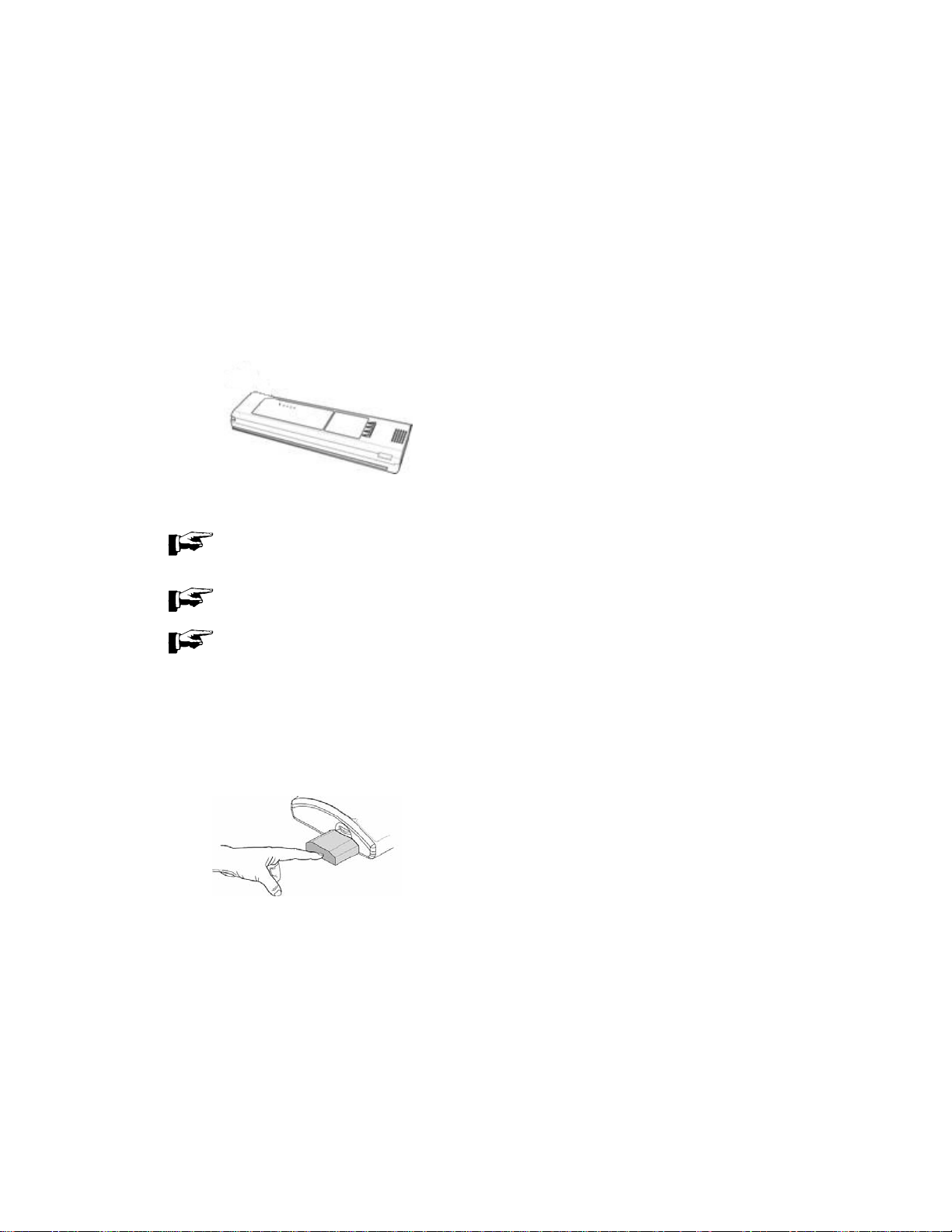
TO INSTALL THE RECHARGEABLE BATTERY
1. Place the Responder 2000 onto a secure, level surface.
2. With the label uppermost and the connector facing inward, insert the battery in the slot on the left side of the
Responder 2000 as shown.
3. Push the battery in until the battery securing latch clicks into place.
2026116-001 Revision B Responder™ 2000 Page 25
Page 26
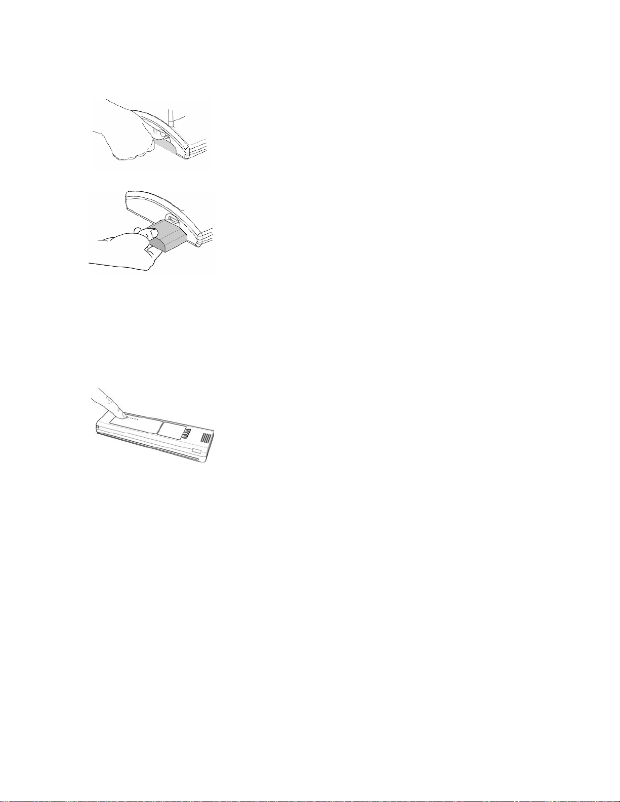
TO REMOVE THE BATTERY
1. Press the battery release until the battery ejects.
2. Pull the battery straight out until it clears the housing.
WARNING: The Responder 2000 should not be stored with the battery inserted. Remove the battery from the
Responder 2000 when storing the device.
TO CHECK THE BATTERY
1. Press the test button on the top of the battery.
2. The row of lights will all light up when the battery is fully charged.
3. If the lights do not light up, or only partially light up, the battery is fully or partially discharged.
2026116-001 Revision B Responder™ 2000 Page 26
Page 27
USING THE BATTERY CHARGER
With a new battery at room temperature, the Responder 2000 will first indicate “Low Battery” while there is still sufficient
charge remaining to perform at least five (5) rescues. As the battery ages, there will be progressively less operating time
available before low battery warning, after low battery warning before therapy inhibit, and after therapy inhibit before
system shutdown. Operation at other than room temperature, especially at low temperature, will also reduce battery
capacity. It is recommended to recharge the battery as soon as practical after the “Low Battery” indication.
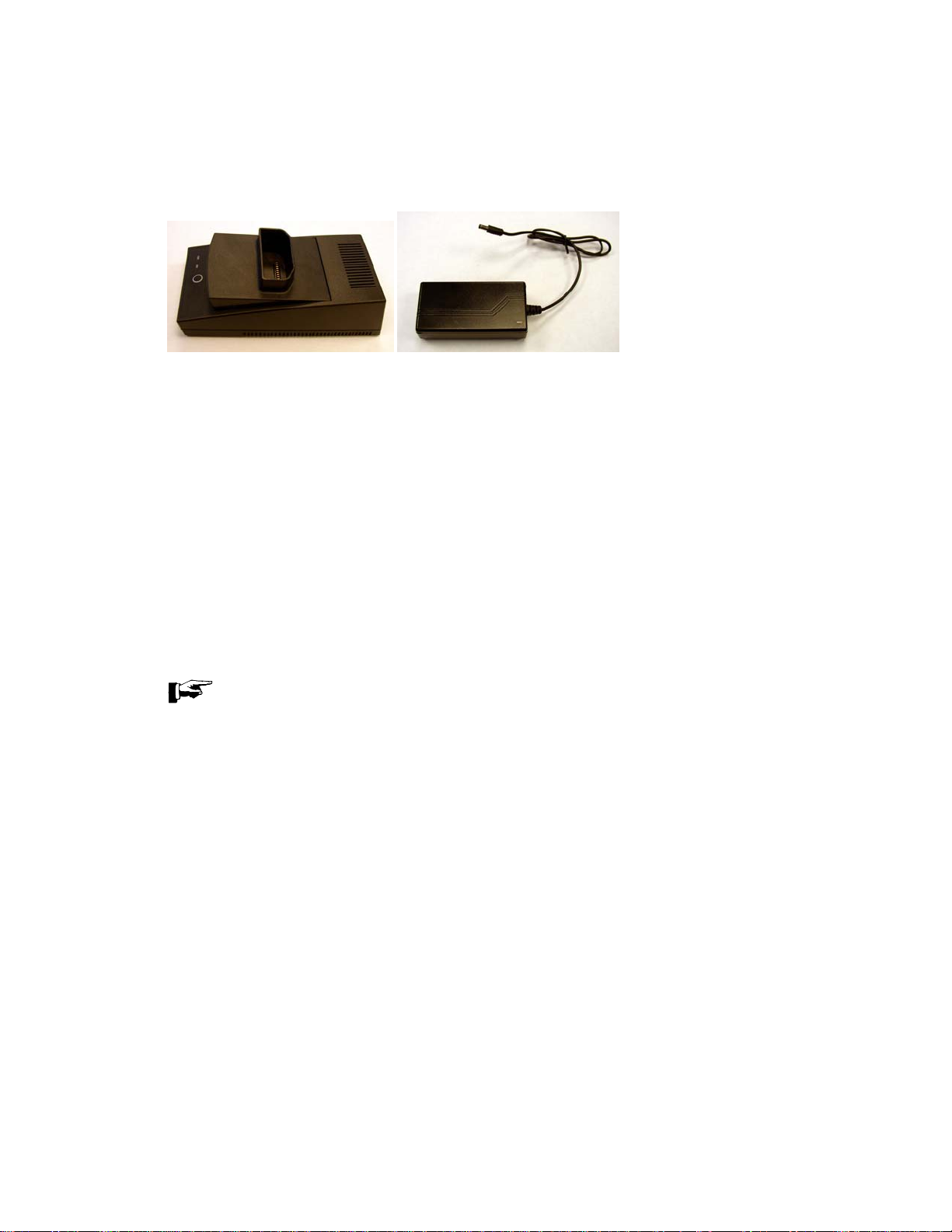
Figure 2.1 Battery Charger and Power Supply
1. Remove the rechargeable battery from the Responder 2000.
2. Plug the power cord into the power supply, plug the power supply into the battery charger, and plug the power cord
into an AC outlet.
3. Insert the battery into the charger and ensure the following:
• Operating Mode light is solid green
• Charge Status light is flashing green.
4. Battery charging starts automatically when battery is put in the battery charger.
Do not push the Calibrate button unless a calibration cycle is desired.
5. The battery will take up to 4 (four) hours to charge in the charger.
6. Remove the battery from the charger when it is charged. The battery is fully charged, when the Mode light is solid
green and the Status light is off.
7. Charging may be terminated early by removing the battery from the charger.
NOTE: If the Charge Status light blinks red, a battery error has occurred during charging. If the Charge Status
light is solid red, a charger error has occurred during charging. Contact Customer Service in the event of an
error during charging.
2026116-001 Revision B Responder™ 2000 Page 27
Page 28

THE BATTERY CALIBRATION CYLE
Time, repeated partial charges and discharges, and battery aging will lead to inaccuracy of the battery fuel gauge. This is
corrected by performing a battery calibration cycle. To initiate a calibration cycle, press the Calibrate button after the
battery has been inserted into the charger. The Mode light will turn red indicating a calibration cycle is in progress. The
calibration cycle consists of a full charge, full discharge, and full charge of the battery. The cycle may take up to 20 hours
to complete. If it is desired to abort the calibration cycle, press the Calibrate button again. When a calibration cycle is
aborted, the Mode light will turn green and the charger will charge the battery. When the calibration cycle is complete, the
Mode light will turn green.
CALIBRATING BATTERY WHILE INSIDE THE RESPONDER 2000
To calibrate a battery while inside the Responder 2000, perform a full cycle of charge, discharge, and charge.
Perform a full cycle of charge for at least 8 hours (see below).
Disconnect the Responder 2000 from AC power. Turn the Responder 2000 on and wait until the device shuts down.
Perform a full cycle of charge for at least 8 hours (see below). When the battery is fully charged, the battery indicator will
display “full battery” (see also section ON-SCREEN INDICATORS).
CHARGING BATTERY WHILE INSIDE THE RESPONDER 2000
Connect the supplied power cord to the socket at the rear of the Responder 2000 then plug in to a suitable AC power
source. The battery will automatically charge when the power cord is connected to the Responder 2000. The battery will
take up to eight hours to charge in the Responder 2000.
WARNING: A protective ground connection by way of the grounding conductor in the power cord is essential for safe
operation. To avoid electrical shock, plug the power cord into a properly wired receptacle, use only the power cord
supplied with the device, and make sure the power cord is in good condition.
WARNING: If the integrity of the external power earth conductor arrangement is in doubt, unplug the device from the
mains AC and operate it from a Responder 2000 rechargeable battery that is charged.
WARNING: If battery is missing or low, the Responder 2000 will not power on if AC power is lost.
2026116-001 Revision B Responder™ 2000 Page 28
Page 29
CONNECTING PADDLES OR PADS
The defibrillator paddle connector attaches to the rear of the Responder 2000. The connector for defibrillator paddles and
pads attaches at the same location. With the label facing out, align the connector over the port and press firmly into place.
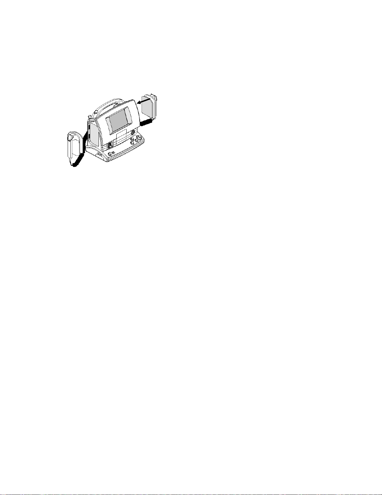
STORING THE PADDLES
The paddles dock easily on each side of the Responder 2000. Simply push and click to secure as shown in Figure 2.2
below. The paddles can be docked with the cables pointing up or down as preferred.
Figure 2.2 Docking the Paddles
2026116-001 Revision B Responder™ 2000 Page 29
Page 30
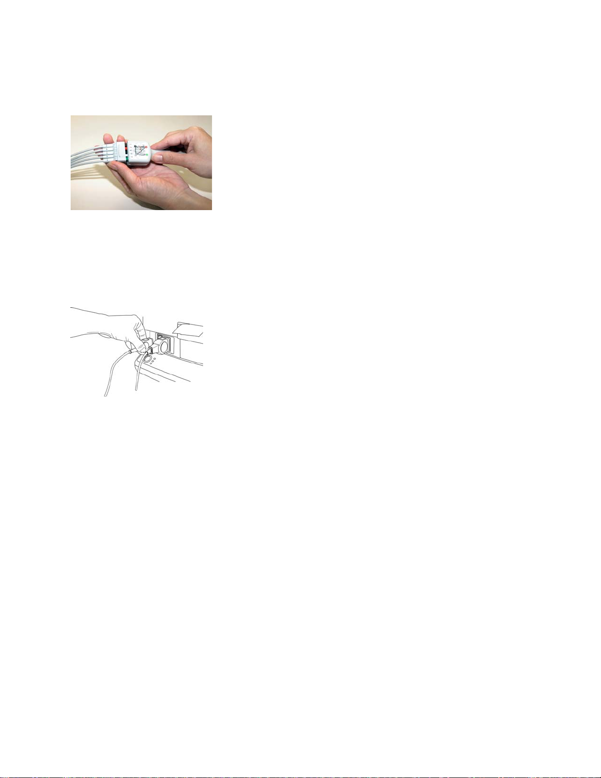
CONNECTING THE ECG LEADS
The Responder 2000 accepts either 3-lead or 5-lead ECG cables. Align the ECG connector with the green port in front
Responder 2000. Push the ECG cable firmly into the ECG port.
Once the ECG connector is attached, a 3-lead or 5-lead wire can be connected to the other end of the cable as shown in
Figure 2.3 below.
Figure 2.3 Attaching the ECG connector to a 5-lead wire
CONNECTING THE SPO2 CABLE (OPTIONAL FEATURE)
The Responder 2000 has SpO
Responder 2000. Push the SpO
as an option on certain models. Align the SpO2 connector with the blue port in front
2
cable firmly into the SpO2 port as shown in Figure 2.4 below.
2
Figure 2.4 Attaching the Oximetry Sensor Lead
2026116-001 Revision B Responder™ 2000 Page 30
Page 31

INSTALLING PAPER INTO THE PRINTER
To install paper into the printer, follow these instructions.
Lift up on the front printer flap as shown by arrow on the Responder 2000. Pull door flap up and forward to open the
printer.
Place paper roll into the printer with the paper end pulled over the top of the printer roller through the opening in the
printer door. Refer to printer door for proper direction of paper.
Close the printer and press the door into place until it clicks. The paper should be protruding from the slot in the printer
housing. The paper may be torn off flush with the front of the Responder 2000 after installation.
PRECAUTION: Printer paper may jam if paper is wet. Printer may be damaged if wet paper is allowed to dry while in
contact with printer elements. Use only printer paper listed in section 7 “Accessories”.
2026116-001 Revision B Responder™ 2000 Page 31
Page 32

POWERING THE RESPONDER 2000
The Responder 2000 operates safely from the following power sources:
• Rechargeable battery
• AC power using the supplied power cord
2026116-001 Revision B Responder™ 2000 Page 32
Page 33

RESPONDER 2000 FRONT AND BACK CONTROLS AND INDICATORS
Speaker Thermal Printer Graphics Display
ECG
Cable port
port
Sp0
2
(Optional)
Power
ON/Off
Button
Status LEDS
Charge Button
Handle
RS-232 Data
Transfer Connection
Manual Button
Rotary Selector
Knob
Shock Button
Paddle/Pad Port
Bed Rail Hooks
(optional accessory)
AC Power
2026116-001 Revision B Responder™ 2000 Page 33
Page 34

RESPONDER 2000 SIDE CONTROLS AND INDICATORS
Paddle Dock
Rechargeable Battery
2026116-001 Revision B Responder™ 2000 Page 34
Page 35

Z-BAR™ INDICATOR
The Z-Bar provides a relative visual graphical indicator of the total transthoracic impedance between the two defibrillation
pads or paddles. The Z-Bar is used in the assessment of:
• Adequate Pad, Paddle , or Spoon placement
• Pad or Paddle quality and integrity
• Pad or Paddle adhesion to the patient’s skin
• Pad or Paddle connection to the Responder 2000
• Provides for quick assessment between OFF and SHORTED
Z-BAR FOR PADS AND PADDLES
SECTION MEASURED IMPEDANCE
1 0-24Ω
2 25-35Ω Lower marginal operating range. Indicates
3 36-135Ω Normal operating range Green
RANGE (OHMS)
DESCRIPTION COLOR FILL
Lower Limit – Non-operational range Red
Yellow
potential degradation in quality or position
4 136-200Ω (for pads)
>136Ω (for paddles)
5 >201Ω (for pads) Upper Limit– Non-operational range Red
Upper marginal operating range. Indicates
potential degradation in quality or position
Yellow
Z-BAR FOR SPOONS
SECTION MEASURED IMPEDANCE
RANGE (OHMS)
1 0-9Ω Lower Limit – Non-operational range Red
2 10-15Ω Lower marginal operating range. Indicates
3 16-75Ω Normal operating range Green
4 76-200 Upper marginal operating range. Indicates
5 >201Ω Upper Limit– Non-operational range Red
DESCRIPTION COLOR FILL
Yellow
potential degradation in quality or position
Yellow
potential degradation in quality or position
2026116-001 Revision B Responder™ 2000 Page 35
Page 36

BUTTONS
There are 4 buttons on the Responder 2000:
1. Power Button
2. Charge Button
3. Shock button
4. Manual Button
POWER BUTTON
To Power on and off the Responder 2000, push the green Power button on the front panel of the Responder 2000.
POWER ON
1. Press the green power button to turn on the Responder 2000. As the Responder 2000 powers on, the system
performs a self-test.
2. After the Responder 2000 is powered on, it will automatically go into Manual Mode. The user can also program it to
enter Semi-Auto Mode or Monitor mode upon power on of the device.
NOTE: If the Responder 2000 indicates an error code when powering on the device:
• Do not use the Responder 2000 (Remove from patient)
• Contact Customer Service with the error code(s).
POWER OFF
Press the green power button to turn off the Responder 2000.
NOTE: If the system is pacing when the power button is pressed, a confirmation box displays requiring an
additional press of the Rotary Selector Knob before the system will turn off.
NOTE: If the button is pressed for five (5) seconds, the Responder 2000 will power down.
NOTE: If AC power is not connected and the battery voltage becomes critically low, the system will display an
error message and then will power off.
2026116-001 Revision B Responder™ 2000 Page 36
Page 37

CHARGE BUTTON
The charge button is used to manually charge the Responder 2000 to the selected energy level. This button is only used
in Manual Mode. This button is disabled when paddles are connected to the Responder 2000. In this case, the
Responder 2000 will be charged only from the paddle charge button. The button will also be disabled when the Z-Bar is
in the red range for pads or spoons.
SHOCK BUTTON
The shock button activates (flashes red) only when the system is charged and ready to deliver therapy to the patient.
Press and hold the shock button until therapy is delivered. This button is disabled when the paddles are connected to the
Responder 2000. If pads or spoons are used, the shock button will only be activated with good impedance.
2026116-001 Revision B Responder™ 2000 Page 37
Page 38

MANUAL BUTTON
The manual buttons brings the operator in or out of the Manual Mode Screen, which allows the operator to begin or end a
shock sequence. If the manual button is pushed during Pacing, the operator needs to confirm entry of Manual Mode
before Manual Mode is entered.
Press the Manual button to enter or exit manual defibrillation mode.
2026116-001 Revision B Responder™ 2000 Page 38
Page 39

ROTARY SELECTOR KNOB
The Rotary Selector Knob is used for scrolling through (a) all areas of the monitoring screen (set-up menus, sub-menus)
(b) selecting soft keys and (c) setting values. This knob is the primary operator navigation and selection vehicle for the
Responder 2000. It can rotate clockwise and counterclockwise. To make a selection, press the Rotary Selector Knob.
The knob is always active while the system application is running.
SOFT KEYS
Soft keys are buttons which are displayed on the graphics display and are activated by using the Rotary Selector Knob.
1. HIGHLIGHT the selection by rotating the Rotary Selector Knob to move the highlight around the screen until the
setting you wish to change is highlighted.
2. SELECT the item by pressing the Rotary Selector Knob until it clicks.
2026116-001 Revision B Responder™ 2000 Page 39
Page 40

STATUS LEDS
There are three system status LEDs on the front panel of the Responder 2000
AC Power (Green LED)
Battery Charging (Yellow LED)
Service Required (Red LED)
The AC Power LED is lit when the Responder 2000 is connected
to external AC power.
The Battery Charging LED is lit when the Responder 2000
Battery is charging in the Responder 2000 or the battery charge
is being maintained.
The Service Required LED is lit when the Responder 2000
requires service. Please take the Responder 2000 out of service
and Contact Customer Service.
PADDLE CONTROLS
The Apex paddle has one button, which controls both charge and shock. Press the Apex paddle button to charge the
Responder 2000. After the Responder 2000 is charged, press both the Apex and Sternum paddle buttons simultaneously
to deliver the shock. Charge and Shock are only activated when the system is in the proper defibrillation mode. If a
button is stuck or remains pressed from before activation of defibrillation, it must be released before a further press is
accepted. When the paddles are connected to the Responder 2000, the charge and shock buttons on the front panel will
be disabled. The charge button is enabled only when the Responder 2000 is in Manual Mode.
RS-232 DATA TRANSFER CONNECTION
This feature is used by factory authorized personnel only.
2026116-001 Revision B Responder™ 2000 Page 40
Page 41

GRAPHICS DISPLAY
MONITOR SCREEN
The monitor screen contains the information bar, Channel 1 and 2 waveforms, information areas for ECG, Pacing and
areas.
SpO
2
INFORMATION BAR
At the top of the screen is the Information bar showing the operating mode of the Responder 2000, the impedance
display, a battery charge status indicator and the current date and time.
MESSAGE AREA
In the middle of the screen, the Responder 2000 displays messages for software and system errors.
2026116-001 Revision B Responder™ 2000 Page 41
Page 42

CHANNEL 1
If 3-lead or 5-lead ECG cables are connected to the Responder 2000, the ECG monitoring waveform is displayed in
Channel 1. The same waveform can be cascaded (continued) from Channel 1 to Channel 2 if desired. Typically, the
system will display the power-on default of ECG II until a different lead combination is chosen.
Each channel has an input source (the ECG lead number) and Gain information associated with its trace waveform. To
change these settings, simply rotate the Rotary Selector Knob to highlight the field and press the Rotary Selector Knob to
select it. Rotate to cycle through the field value options and press the Rotary Selector Knob again to confirm the new
setting.
The system will display waveforms in channel 1 based on the following conditions:
• If just an ECG cable is connected, the input sources available for the operator to select on channel 1 are:
• If ECG is not connected, but Pads, Paddles, or Spoons are, the channel will automatically convert to the
• If Pads, Paddles, or spoons are connected along with the 5-lead ECG cable, the following source input options
o When an ECG cable is connected: I, II, III, aVR, aVL, aVF, V, Paddles (with Paddles off message)
NOTE: If the ECG cable becomes disconnected or falls off, a warning message is displayed.
connected input if the Auto-Switch source is turned on.
are available:
o I, II, III, aVR, aVL, aVF, V, Pads, Paddles, Spoons
o If the ECG cable or the Pads, Paddles, or Spoons become disconnected or fall off, a warning
message is displayed.
o If no ECG or Pads are connected, it will indicate that no leads are connected by showing dashed line.
CHANNEL 2
Displays one of the following selectable choices:
• Cascaded waveform from Channel 1
• The SpO
waveform (if sensor is connected and Responder 2000 has this optional feature.)
2
2026116-001 Revision B Responder™ 2000 Page 42
Page 43

INFORMATION AREAS
The right side of the screen contains specific monitoring information for ECG (top box), SpO2 (Oximetry) and Pacing if
these two options are present. To access the information areas:
1. Rotate the Rotary Selector Knob until the outline of the information box is highlighted then press to select the
information area.
2. Rotate the Rotary Selector Knob again to highlight a particular item within the highlighted box to change the setting.
Press to select the item then turn the knob to scroll through the value range for that item.
3. Press to confirm a new value.
ECG INFORMATION BOX
The ECG Information box shows ECG information.
The value shown for heart rate is determined from the ECG of channel 1 input, which can be from ECG electrodes or
Pads, paddles or spoons.
The low and high alarm ECG limits can also be set from this box.
SPO2 INFORMATION (OPTIONAL)
When the pulse oximetry option is present and a sensor is connected, the SpO2 Information area displays SpO
information. The SpO2 information area displays % saturation and pulse rate. SpO2 high and low alarm limits can be
changed from the SpO
information box.
2
PACING INFORMATION (OPTIONAL)
When the Pacing option is present and pads are connected, pacing can be turned on. Pacing mode, rate, and pace
current can be set within this information box.
2
2026116-001 Revision B Responder™ 2000 Page 43
Page 44

ON-SCREEN INDICATORS
BATTERY INDICATOR
The battery indicator graphically displays the approximate percentage of battery life remaining.
Four (4) ranges will be shown:
~0-25% ~25-50% ~50-75% ~75%-100
When AC is not present and the display falls to a single bar, the bar turns red to indicate that the battery should be
charged soon, or that a fully charged battery should be inserted.
When the Responder 2000 is connected to AC, a "lightning bolt" indicates that the battery is being charged or charge is
being maintained if the battery is full. When AC is not present, no lightning bolt is displayed.
When no battery is present, the following indicator is displayed.
BATTERY WARNING MESSAGES
When running the Responder 2000 from the rechargeable battery, a low battery may cause the following warning
messages:
1. Message 312
When battery voltage is low, Message 312 is displayed. Plug the device into AC to charge the battery, or insert
a fully charged battery.
2. Message 313 and Message 318
When battery voltage is very low, the Message 313 and Message 318 alternate, and therapy is inhibited. Plug
the device into AC power to charge the battery, or insert a fully charged battery.
3. Message 314
When battery voltage is critically low, Message 314 is displayed momentarily and the system shuts down. Plug
the device into AC to charge the battery, or insert a fully charged battery. Turn the device back on if in use.
NOTE: As the battery ages, it will discharge faster and there will be less operating time available before low
battery warning, therapy inhibit and system shutdown. Replace an aged battery to restore the operating time.
2026116-001 Revision B Responder™ 2000 Page 44
Page 45

HEART RATE
The red heart symbol displayed in the ECG information area will graphically indicate the heart rate by beating at the
rhythm of the patient’s heart rate. For clear viewing, the heart will display upon detection of an R-Wave for 200ms. The
Responder 2000 uses the average of the time between the last eight (8) detected QRS complexes, with the two outlying
values discarded, to calculate the displayed heart rate. The heart rate display is updated once every 2 seconds.
The Responder 2000 will respond to a change in heart rate from eighty (80) bpm to one hundred and twenty (120) bpm in
less than five (5) seconds. The Responder 2000 will respond to a change in heart rate from eighty (80) bpm to forty (40)
bpm in less than ten (10) seconds in the conditions specified in ANSI/AAMI EC13 section 4.1.2.1 f).
WARNING: Do not rely solely on heart rate readings; assess the patient at all times.
2026116-001 Revision B Responder™ 2000 Page 45
Page 46

2026116-001 Revision B Responder™ 2000 Page 46
Page 47

SECTION 3: USING THE RESPONDER 2000
OVERVIEW
This section describes how to prepare the Responder 2000 and the patient and using the Responder 2000.
TOPIC PAGE #
RESPONDER 2000 PREPARATION 48
PATIENT PREPARATION 48
USING PADS 48
USING ECG ELECTRODES 53
USING EXTERNAL PADDLES 55
USING INTERNAL PADDLES (SPOONS) 57
CHOOSING A DEFIBRILLATION MODE 60
MANUAL MODEError! Reference source not
found.
SEMI-AUTO SHOCK MODE 64
ECG MONITORING 66
NON-INVASIVE PACING (OPTION) 69
PULSE OXIMETRY (OPTION) 74
PRINTING 76
SNAPSHOT 77
HISTORY MENU
RESPONDING TO ALARMS 78
ADJUSTING HEART RATE ALARM LIMITS 80
SETTING THE ECG SOURCE AND GAIN 80
Error!
Bookmark
not defined.
77
2026116-001 Revision B Responder™ 2000 Page 47
Page 48

RESPONDER 2000 PREPARATION
1. Setup Responder 2000 according to directions in Section 2.
2. Verify Responder 2000 Indications for Use are being met. Refer to Section 1.
3. Verify Responder 2000 Safety Terms and Conditions are being met. Refer to Section 1.
Prepare the patient according to directions in the PATIENT PREPARATION in this section.
WARNING: The Responder 2000 is restricted to a single patient at a time.
4. Turn on the Responder 2000 by pushing the Power button on the front panel.
5. The Responder 2000 software will:
• Perform a Start-up self test
• Display the Responder 2000 splash screen
• Illuminate all therapy buttons for a few seconds
• Output a tone
• Illuminate the Service LED momentarily
6. When the self-tests are complete, the default operating mode is displayed indicating that the
Responder 2000 has successfully passed the start-up self-test and is ready for patient use.
NOTE: If the Responder 2000 issues an Error during this process:
• Do not use the Responder 2000 (Remove from patient)
• Write down any displayed error codes and contact Customer Service
WARNING: Do not use batteries, pads, cables, or optional equipment not specifically approved for the Responder 2000.
The use of unapproved equipment may cause the Responder 2000 to function improperly during a rescue.
PATIENT PREPARATION
Follow these recommendations to prepare the patient’s skin:
• Remove clothing from the patient’s chest.
• If necessary, shave excessive chest hair. Use care not to nick or cut the skin. Avoid placing pads over broken or
irritated skin.
• Briskly dry the skin with a towel or gauze to increase capillary blood flow in the tissues, remove skin cells, dirt and
excess oil.
USING PADS
The Pads listed in Section 7 of this manual are compatible with the Responder 2000. Adhere to the Precaution and
Warnings, Applying PADS, Placement of PADS, Changing of PADS, PADS OFF or SHORTED notifications in this
section.
2026116-001 Revision B Responder™ 2000 Page 48
Page 49

APPLYING PADS
• The pads are not sterile and cannot be sterilized. They are for single patient use and need to be disposed after use.
• Once the pads are applied to the patient they should not be repositioned.
• After placing the pads on the patient, visually check that the pads are firmly attached.
• The skin is a poor conductor of electricity; therefore preparation of the patient’s skin is important to facilitate good
pads-to-skin contact.
• To ensure proper rhythm analysis by the Responder 2000, patient preparation and hook up must be properly
performed. Proper application and placement of the pads are essential for high-quality ECG monitoring. Good
contact between the pad and skin minimizes motion artifact and signal interference.
SPECIAL PAD PLACEMENT SITUATIONS
The following descriptions are for special placement situations.
Obese Patients or Patients with Large Breasts
Apply the pads to a flat area of the chest, if possible. If skin folds or breast tissue prevent good adhesion, it may be
necessary to spread skin folds apart to create a flat surface.
Thin Patients
Follow the contour of the ribs and spaces when pressing the pad onto the torso. This limits air space or gaps under the
Therapy pads and promotes good skin contact.
Patients with Implanted Pacemakers
Place the pads away from the internal pacemaker generator.
2026116-001 Revision B Responder™ 2000 Page 49
Page 50

ANTERIOR-LATERAL PLACEMENT OF PADS FOR DEFIBRILLATION/SYNC SHOCK (MOST COMMONLY USED)
1. Turn off the Responder 2000. Connect the pads connector to the Responder 2000.
2. Shave the application points; this improves conductivity and makes the removal of pads easier.
3. Remove the protective liner by starting with the pad cable connection end. Slowly peel back the protective liner from
the pads.
4. Place the anterior (Sternum) pad on the patient’s right upper torso, lateral to the sternum and below the clavicle.
5. Place the (Apex) Therapy pad lateral to the patient’s left nipple, with the center of the pad in the midaxillary line, if
possible. For female patients, position the pad under the breast.
6. Starting from one edge, firmly press the pad onto the patient’s chest to eliminate air pockets between the gel surface
and the skin.
7. Connect pads cable to the pads.
2026116-001 Revision B Responder™ 2000 Page 50
Page 51

ANTERIOR-POSTERIOR PLACMENT OF PADS FOR NON-INVASIVE PACING AND DEFIBRILLATION/SYNC
SHOCK
1. Turn off the Responder 2000. Connect the pads connector to the Responder 2000.
2. Shave the application points; this improves conductivity and makes the removal of pads easier.
3. Remove the protective liner by starting with the pad cable connection end. Slowly peel back the protective liner from
the PADS.
4. Place the posterior pad on the left side of the patient’s back, behind the heart in the intrascapular area. Apply the pad
to the patient’s skin. Do not place the pad over bony prominence of the spine or scapula.
5. Place the pad on the left side of the patient’s chest. The upper edge of the pads should be just below the nipple and
apply to the patient skin.
6. Starting from one edge, firmly press the pad onto the patient’s skin to eliminate air pockets between the gel surface
and the skin.
7. Connect pads cable to the pads.
2026116-001 Revision B Responder™ 2000 Page 51
Page 52

CHANGING PADS
The pads must be changed after a therapy sequence (defibrillation or one (1) hour of continuous pacing) is delivered.
Turn off pacing and make sure Channel 1 lead source is not “Pads”.
Exit Manual Mode or Semi-auto Shock before disconnecting pads.
Disconnect pad connector from the Responder 2000.
Remove pads from the patient
Prep skin and attach new pads to the patient, in a slightly different location to avoid irritation or burns.
Attach pad connector to Responder 2000.
Select desired mode from the Systems Menu.
PADS OFF NOTIFICATION
For the pads off notification, check the following:
• Check for proper skin preparation
• Check for adequate pad contact between the pad and the patient’s skin
• Check for expired / dry pads
• Check to see that the pads are properly connected the Responder 2000.
• Change pads
PADS SHORTED NOTIFICATION
Check to see if pads are placed too close to each other and, if so, separate the pads ensuring that there is enough
distance between the pads
Change pads
NOTE: Anterior / Posterior pads placement may alleviate a PADS SHORTED message.
NOTE: If impedance at the pads/paddles is too low to shock the patient, the ECG in the display will automatically
switch from pads/paddles ECG to ECG II, if this feature is activated from the settings. To go back to pads/paddles ECG
you have to switch back manually.
WARNING: Due to the unique impedance characteristics of the patient, the Responder 2000 may not be able to shock the
patient.
2026116-001 Revision B Responder™ 2000 Page 52
Page 53

USING ECG ELECTRODES
The ECG electrodes are required for operating the Responder 2000 in external demand pacing mode, ECG Monitoring
mode, and during Semi-Auto mode..
In order to ensure proper demand pacing, the Responder 2000 requires a high quality surface ECG signal between the
patient’s skin surface and the ECG electrode. Standard 3-lead or 5-lead configuration is used to monitor the patient’s
electrocardiogram.
NOTE: The skin is a poor conductor of electricity, therefore preparation of the patient’s skin is important to
facilitate good electrode to skin contact. When cleaning the patient’s skin, NEVER use alcohol or tincture of
benzoin, as this increases skin resistance.
APPLYING ECG MONITORING ELECTRODES
1. Attach the ECG patient cable lead wires to the ECG electrodes. The lead wires are color coded according to AHA or
IEC standards.
2. Plug the ECG patient cable into the ECG input connector (green) located on the front panel of the Responder 2000.
3. Prepare the patient’s skin according to the Patient Preparation section in this manual.
4. Peel the backing off the electrodes and press the electrodes firmly onto the patient’s skin.
2026116-001 Revision B Responder™ 2000 Page 53
Page 54

USING ECG ELECTRODES (CONTINUED)
3-Lead Placement
RA/R placement: Directly below the clavicle and near the right shoulder
LA/L placement: Directly below the clavicle and near the left shoulder
LL/F placement: On the left lower abdomen
5-Lead Placement
RA/R placement: Directly below the clavicle and near the right shoulder
LA/L placement: Directly below the clavicle and near the left shoulder
RL/N placement: On the right lower abdomen
LL/F placement: On the left lower abdomen
V/C placement: On the chest; the position depends on the required lead selection.
5. Select a site where the signal will not be interfered with by either movement or bones. Avoid touching the tape and
electrode gel.
6. Make sure there is adequate space (approximately 3 cm) between the pads and the ECG monitoring electrodes.
7. The various ECG leads can be individually selected and viewed on the LCD screen. The ECG Monitoring mode is
the ideal screen for viewing any of the ECG leads without therapy intervention.
2026116-001 Revision B Responder™ 2000 Page 54
Page 55

USING EXTERNAL PADDLES
To defibrillate using external paddles:
WARNING: Use only paddles specified in Section 7 of this manual. The use of unapproved equipment may cause the
Responder 2000 to malfunction and may hinder patient treatment.
WARNING: Risk of Skin Burns / Equipment Damage — Do not apply the paddles over sternum or clavicle, nipples,
implanted pacemaker or defibrillator devices.
1. Remove the Paddle Set from the Paddle cradles by pulling the paddles outward and out of the paddle docks.
2. Carefully dry the paddles and handles in particular, if they are damp or wet.
3. Apply electrode gel to the paddles. Do not distribute electrode gel by rubbing the paddles together.
4. Apply paddles to the patient’s bare chest, using the anterior-lateral placement (or in accordance with your
organization’s protocol). Apply the paddles on the patient's thorax such that the greatest possible amount of energy
flows through the myocardium. The imaginary line connecting the paddle centers should be identical with the cardiac
median line.
5. Press the paddles firmly onto the thorax (the ECG appears on the monitor screen).
6. Initiate energy storage with the button on the APEX paddle (a).
When the selected energy is stored, the device emits an audio signal and the message "Stand Clear, Push Paddle
Shock” appears.
2026116-001 Revision B Responder™ 2000 Page 55
Page 56

7. Now trigger the shock within 30 seconds. To do so, simultaneously press the buttons (A) and (B) on the paddles.
NOTE: When the patient is a child under 8 years of age or weighs less than 55 lbs (25 kg), the Responder 2000
should be used with Pediatric Defibrillation paddles and pediatric energy protocols. These paddles are
integrated into the standard paddle set and are available by removing the adult contact plates off the paddles.
The paddles have two different contact surfaces; a large one (can be removed) for the defibrillation of adults and a smaller
one for the defibrillation of children.
Remove the large contact surface for pediatric use:
• Press on the lock button 1
• Slide the contact surface 2 towards the front and take it off the paddle.
• When re-installing it, the large contact surface must audibly click into place.
2026116-001 Revision B Responder™ 2000 Page 56
Page 57

USING INTERNAL PADDLES (SPOONS)
To defibrillate using internal paddles:
WARNING: Shock Hazard – Always switch off the device before exchanging the defibrillation electrodes and internal
spoons.
NOTE: If you are using internal electrodes with the Responder 2000, defibrillator charging and shock delivery
must be initiated with corresponding buttons on the front panel of the Responder 2000.
NOTE: The selectable energy when using internal paddles is as follows: 2, 3, 5, 7, 10, 15, 20, 30, and 50 Joules
NOTE: Internal defibrillation is only allowed in Manual Mode!
If Semi-Auto Mode is selected while spoons are attached, the Responder 2000 will automatically switch to
Manual Mode.
1. Setup internal paddles according to instructions supplied with them.
2. Connect the internal paddles to the paddle dock on the back of the Responder 2000.
3. Apply paddles to the patient’s heart.
Spoon-shaped electrodes are used for internal defibrillation. Their contact surface must match the dimensions of the
heart. The spoons must make full contact with the heart. There is a choice of 3 different spoon sizes. You can use either
two spoon electrodes or one spoon electrode and one external counter electrode for defibrillation.
Sterilize internal electrodes before each use (see section “Maintenance & Service”).
2026116-001 Revision B Responder™ 2000 Page 57
Page 58

INSERTING THE SPOON ELECTRODE
• Screw the counter nut 2 onto the electrode as far as it will go.
• Screw the contact paddle 1 into the handle as far as it will go, then bring it into the appropriate position.
• Now fix the contact paddle by screwing the counter nut 2 tight against the handle 3.
2026116-001 Revision B Responder™ 2000 Page 58
Page 59

DEFIBRILLATOR APPLICATION GUIDELINES
Observe the following guidelines to ensure successful and safe defibrillation. Otherwise the lives of the patient, the user
and bystanders are in danger.
WARNING:
WARNING:
to come into contact with metal parts to prevent unwanted pathways for the defibrillation current which may endanger the
assistants. For the same reason, do not position the patient on wet ground (rain, accident in swimming pool).
WARNING:
in contact with the patient.
WARNING:
current. After use of flammable skin cleansing agents, wait until they have completely dried.
WARNING:
All tasks must be clearly assigned.
WARNING:
Always switch off the device before exchanging the defibrillation electrodes.
WARNING:
Defibrillating a patient with an implanted pacemaker is likely to impair the pacemaker function or cause damage to the
pacemaker.
For this reason: - Select the smallest energy level possible for the application,
WARNING: Equipment Damage
Disconnect transducers and devices that are not defibrillation-proof from the patient before delivering the shock.
WARNING: Equipment Damage
Do not defibrillate the patient with a second defibrillator, while defibrillation electrodes (paddles, pads) of the first device
are applied. If the use of a second defibrillator is inevitable, disconnect the electrodes from the first device or remove them
from the patient
Defibrillating a patient with normal heart rhythm may induce ventricular fibrillation.
Position the patient flat on a hard surface where he is electrically insulated. The patient must not be allowed
Do not allow the defibrillation electrodes to come into contact with other electrodes or metal parts which are
The patient's chest must be dry, because moisture can cause unwanted pathways for the defibrillation
The operator and all assistants must be briefed regarding the preparations for and execution of defibrillation.
• Immediately prior to the shock: interrupt heart massage and artificial respiration, disconnect tube connections,
and warn bystanders.
• Ensure that no conductive connection between the patient and bystanders exists during defibrillation.
• Before delivering the shock, verify that the charged and selected energies are the same.
Shock Hazard
Pacemaker Patients
- Do not apply the defibrillation paddles in the vicinity of the pacemaker,
- Have an external pacemaker at hand,
- Check the implanted pacemaker for proper functioning as soon as possible after the shock.
.
2026116-001 Revision B Responder™ 2000 Page 59
Page 60

DEFIBRILLATION MODES
The Responder 2000 has two (2) modes of defibrillation, each with a customized display view. The modes are as follows:
Manual Mode
Semi-Auto Mode
CHOOSING A DEFIBRILLATION MODE
The Responder 2000 default operating mode is Manual mode. To change the default mode, refer to Section 4 on
Configuring the Responder 2000.
1. To choose an operating mode, open the System Menu.
Operator manually selects energy level appropriate for the patient’s age, manually
charges the unit, and manually delivers therapy to the patient. In this mode, energy
can be selected manually or by using the auto-sequence energy settings. In this
mode, shock can be delivered in Synchronous (Sync) with a R-wave by selecting the
Sync Button. If Sync is selected, the Responder 2000 will attempt to synchronize
the shock. If it is unable to synchronize within 2 seconds, it will not deliver the
shock. Default for manual mode is No Sync.
In this mode, the operator can analyze the patient’s heart rhythm. Upon detection of
a shockable rhythm, the Responder 2000 will automatically charge and prompt the
operator to press the shock button to allow therapy to be delivered to the patient. In
Semi-Auto Mode, the Responder 2000 charges the unit to user preset energy
settings.
2. Select the desired mode: Manual Mode or Semi-Auto Mode.
3. Ensure that the ECG monitor waveform shown in Channel 1 is set to the correct input source and gain. If not, follow
the directions given in Setting the ECG Source and Gain in this chapter to adjust.
2026116-001 Revision B Responder™ 2000 Page 60
Page 61

MANUAL MODE
Operator manually selects energy level appropriate for the patient’s age, manually charges the unit, and manually delivers
therapy to the patient. In this mode, energy can be selected manually or by using the auto-sequence energy protocol.
Default method of delivering therapy in the manual mode is No Sync, namely, therapy is delivered as soon as the shock
button is pressed. If the user chooses the Sync mode in the Manual Mode screen, therapy will not be delivered if the
device cannot synchronize with the patient’s R-wave within 2 seconds after the shock button is pressed.
TO USE MANUAL MODE
Manual Mode can be selected from the System Menu or by pressing the Manual button. If Manual Mode is set as the
default mode, the Responder 2000 will power up in Manual Mode after turning the Responder 2000 on. It will then flash
the yellow Charge button.
Auto Sequence Selection of Energy Manual Selection of Energy
1. To select the desired energy level appropriate for the patient’s age, turn Rotary Selector Knob counterclockwise to
go up and down the list. The operator will be able to select the following energy values:
PRECAUTION: Select the energy level appropriate for the patient’s age. The Responder 2000 does not select the
energy or shock sequences based on the defibrillation pads connection.
For pads and paddles:
2, 3, 5, 7, 10, 15, 20, 30, 50, 70, 100, 150, 200, and 270 Joules
For internal paddles/spoons:
2, 3, 5, 7, 10, 15, 20, 30, and 50 Joules
2026116-001 Revision B Responder™ 2000 Page 61
Page 62

TO USE MANUAL MODE (CONTINUED)
2. After selecting desired energy, press the Rotary Selector Knob.
3. Push the Charge button.
4. Warn bystanders to stand clear of the patient. Ensure that you do not touch the patient.
5. After the Responder 2000 is charged, push and hold the Shock button(s) until therapy is delivered.
6. The message Shock Delivered displays for eight (8) seconds once the shock has been delivered.
7. At any time during the manual defibrillation sequence, the operator can change the energy setting or exit the mode
completely by turning the Rotary Selector Knob and pressing Exit OR by pushing the Manual button.
NOTE: The operator has thirty (30) seconds to deliver therapy before the Responder 2000 disarms and
aborts therapy.
NOTE: Alarm Silence symbol is displayed, indicating that no audible tone warnings will be heard, only
written warning message will be displayed on the graphics display.
2026116-001 Revision B Responder™ 2000 Page 62
Page 63
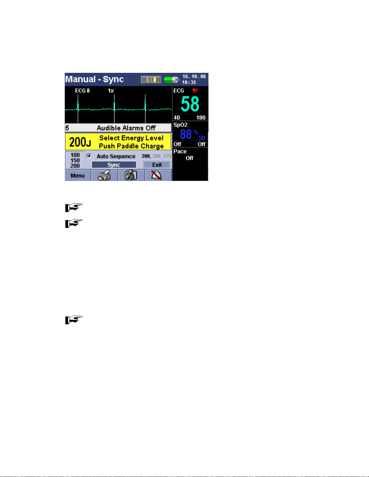
NO SYNC/SYNC OPTION
The Responder 2000 has a No Sync/Sync Option available in Manual Mode only. If No Sync is selected, shock is
delivered immediately. When Sync is selected, full length R-wave sync marks are drawn on display and shock delivery is
synchronized with the R-wave. No Sync is selected by default.
1. Turn the Rotary Selector Knob to No Sync/Sync toggle button
2. Press the Rotary Selector Knob to select Sync option
PRECAUTION: Observe the ECG rhythm. Confirm that the full length sync bar appears near the middle of each QRS
complex. If the sync bars do not appear or are displayed in the wrong locations change the lead source.
NOTE: Every time after a Sync Shock is delivered; the device resets to “No Sync”.
NOTE: Select a lead that provides a unipolar R-wave with a minimum amplitude of 1 mV and a low-amplitude T-
AUTO SEQUENCE
wave.
In Manual Mode, there is also an Auto Sequence option. In Auto Sequence, three energy levels can be pre-set. When
this option is selected, the Responder 2000 automatically selects the first pre-set energy and prompts the operator to
push the Charge button. After the Responder 2000 is charged, it will prompt the operator to push the Shock button(s).
After a shock is delivered, the Responder 2000 automatically selects the next energy level. After all three pre-set shocks
have been delivered; the Responder 2000 selects the last energy level. All shocks after the third shock will be at that
level.
NOTE: In Auto Sequence if the user wants to deliver a Sync Shock, Sync must be selected individually for all
shocks in Auto Sequence.
2026116-001 Revision B Responder™ 2000 Page 63
Page 64

SEMI-AUTO SHOCK MODE
In this mode, the Responder 2000 will analyze the patient’s heart rhythm. Upon detection of the shockable rhythm, the
Responder 2000 will automatically charge and prompt the operator to press the shock button to allow therapy to be
delivered to the patient.
Use of spoons is not be allowed in Semi-Auto Shock Mode. If spoons are attached to the Responder 2000 during power
on, selection of Semi-Auto Mode, or while already in Semi-Auto mode, the device will automatically switch to Manual
Mode immediately. The Message Area will display “Switched to Manual Mode” for six seconds.
TO USE SEMI-AUTO SHOCK MODE
Upon the detection of a shockable cardiac rhythm, the Semi-auto Shock mode provides the ability to automatically charge
up to three (3) defibrillation shocks in a pre-programmed auto sequence and advise the operator when to manually press
the flashing shock button(s) to deliver therapy.
Semi-Auto Shock mode can be selected from the System Menu. If Semi-Auto Shock mode is set as the default mode, the
Responder 2000 will automatically go into Semi-Auto Shock mode after turning the Responder 2000 on.
NOTE: Semi-Auto Mode is not allowed with Paddles as Channel 1 Source.
2026116-001 Revision B Responder™ 2000 Page 64
Page 65

TO USE SEMI-AUTO SHOCK MODE (CONTINUED)
1. Press the Rotary Selector Knob to Analyze.
2. If a shockable rhythm is detected, the Responder 2000 will automatically charge to the appropriate energy level. The
sequence starts with the first displayed value then increments through the three increasing values.
3. When the charge is complete, the operator is prompted to push Shock button(s).
NOTE: The operator has thirty (30) seconds to deliver therapy before the Responder 2000 disarms and aborts
therapy.
4. After three (3) shocks in Semi-auto Shock mode, the Responder 2000 continues to use the last delivered energy.
2026116-001 Revision B Responder™ 2000 Page 65
Page 66

ECG MONITORING
This section describes the basic ECG monitoring functions of the Responder 2000.
The Responder 2000 can be used for ECG monitoring. The monitoring function allows the operator to monitor through:
• Pads
• 3-lead ECG Electrodes
• 5-lead ECG Electrodes
If both pads and monitoring electrodes are connected, monitoring allows you to select a lead from the 3-lead, 5-lead ECG
source, or to monitor through the pads.
Configurable heart rate and arrhythmia alarms clearly communicate patient status, both audibly and visually.
See Setting the ECG Source and Gain in this section for changing these settings.
ACTIVATING AND DEACTIVATING FILTERS
Activating muscle and AC line filters makes the displayed ECG insensitive to AC interference and muscle tremor.
However, the filters alter the ECG signal, and a filtered signal is not suitable for diagnosis (displayed or printed ECG).
NOTE: Active filters will alter the ECG signal. Switch off the filters to obtain a diagnostic ECG.
NOTE: ECG signals acquired with pads, paddles, or spoons cannot be used for diagnostic purposes.
MONITORING HEART RATE
WARNING: No Asystole Alarm
The defibrillator gives asystole alarm only when the heart rate falls below the low HR limit. Therefore, do not disable the
low HR limit.
WARNING: Incorrect HR / No HR Alarm
In the presence of arrhythmias and morphological changes of the ECG, the device may not be able to calculate the
correct heart rate. Beats may be counted twice or may be ignored
The default heart limits are 40 and 180 bpm and the audio alarm is disabled. The audio alarm can be enabled
permanently from the setup menu.
The defibrillator reports an alarm condition if the HR exceeds one of the alarm limits for more than 10 seconds:
When the parameter reading returns to normal range, the audio alarm stops.
For information on setting and changing alarm parameters, refer to chapter Responding to Alarm and chapter Adjusting
Heart Rate Alarm Limits in this section.
NOTE: The defibrillator can be set up to automatically activate the alarm tone on power up. The default alarm
limits can also be adjusted in the setup menu.
During patient transport the device may fail to identify arrhythmias due to motion artifact.
• The audio alarm sounds (configurable)
• The recorder starts (configurable)
• The alarm is indicated on the display
2026116-001 Revision B Responder™ 2000 Page 66
Page 67

MONITORING PACEMAKER PATIENTS
When monitoring the heart rate of pacemaker patients, only the patient's QRS complexes must be counted and pacer
pulses must be rejected. For this purpose, the Responder 2000 has an electronic pacer pulse suppression algorithm
which rejects the pacer pulses so they are not counted as QRS complexes. Depending on the pacemaker model used
and on the position of the electrodes, the compensation pulse following every pacer pulse may be considered as a QRS
complex. Every pacemaker must provide an oppositely charged current (reverse current) after delivering a pacing pulse.
In this situation and when the pacer pulse is ineffective, the displayed heart rate may be misinterpreted, and the device
will not give alarm in the presence of bradycardia or asystole.
Always monitor pacemaker patients by means of separate ECG electrodes and not via the defibrillation electrodes.
As an additional precaution, monitor pacemaker patients by means of pulse oximetry.
It depends on the pacer pulse parameters, whether or not the compensation pulse is counted as a QRS complex.
For pacemaker patients, the ECG R-wave signal size should be greater than 1 mV.
WARNING: No HR Alarm — If several adverse conditions exist at once during monitoring of pacemaker patients, the
possibility that pacer pulses are interpreted (and counted) as QRS complexes should be considered. Therefore,
pacemaker patients should always be watched closely.
2026116-001 Revision B Responder™ 2000 Page 67
Page 68

NON-INVASIVE PACING (OPTION)
This section describes the noninvasive transcutaneous pacing option available with the Responder 2000 and describes
how to perform pacing.
Application and Functional Description
The transcutaneous pacemaker of the Responder 2000 is used for external (transchest) cardiac stimulation in
emergencies. It is applied temporarily in cases of acute arrhythmia, such as cardiac arrest or Stokes-Adams attacks.
Specific forms of bradycardia and tachycardia can also be treated with the pacemaker.
The pacemaker offers two modes of operation: demand and fixed-rate pacing (“Fix”).
The pacer pulses are delivered via the adhesive defibrillation electrodes (pace pads). Electrodes for adults and for
children can be used. Separate ECG electrodes must be applied for acquisition of the ECG signal.
WARNING: For treatment of patients with implantable devices such as permanent pacemakers or cardioverter
defibrillators, consult a physician and the instructions for use provided by the device’s manufacturer.
WARNING: Use demand mode pacing whenever possible. Use fixed mode pacing when motion artifact or other
ECG noise makes R-wave detection unreliable or when ECG monitoring electrodes are not available.
PRECAUTION: The maximum duration of pacing is recommended at one (1) hour. If patient condition requires prolonged
continuous pacing it is recommended that pads should be replaced to ensure maximum patient benefit. Prolonged pacing
particularly in neonates or adults with severely restricted blood flow, may cause burns. Periodic inspection of the
underlying skin is recommended.
PRECAUTION: Check that pad adhesive is intact and undamaged.
PRECAUTION: If the battery is removed while pacing and there is not AC Power, the pacing settings need to be re-set
when the battery is inserted again.
NOTE: The message “Please wait” will be displayed during the period when the Responder 2000 is not pacing,
because of change of lead. The Responder 2000 will not pace during this time.
WARNING: Shock Hazard
Due to their functional requirements, pacemakers operate with high voltages and are therefore equipped with specially
protected outputs. Nevertheless, it is important not to touch live contacts with conductive metal objects, such as tweezers,
as long as the pacemaker is operating. Currents exceeding 10µA may induce ventricular fibrillation,
if they flow through the heart. Observe the following sequence of operating steps when turning the pacemaker on and off.
2026116-001 Revision B Responder™ 2000 Page 68
Page 69

TO USE PACING MODE
To Enable Pacing:
1. Apply ECG electrodes to patient.
2. Connect ECG electrodes to the device.
3. Turn on the Responder 2000.
4. Check ECG and vital signs
5. Attach pace pads to patient.
6. Connect pace pads to the Responder 2000.
7. Use Rotary Selector Knob to move focus Pacing Info box, at the display’s lower right.
8. Select the Pacing Info box. If pacing is not enable, the Pacing Info box is not selectable.
9. Use Rotary Selector Knob to traverse though selectable items.
10. Turning clockwise, the following items should be selectable, in order, wrapping around:
a) Pacing Type (Fixed, Demand), Default is Demand.
b) PPM ( 30-180 PPM, increments of 5), Default is 60 PPM
c) Exit Pacing Info Box (“x” in corner)
d) Pacing On/Off/Pause (Pause is only available when Pacing is turned On)
e) Pacing Current (0mA-140mA, increments of 5). This option is only selectable when pacing is turned on.
11. Turn the Rotary Selector Knob to turn on the pacing.
12. When Pacing is turned on, focus automatically goes to the Pacing Current selection. Set desired pacing current.
13. Turn the rotary knob to select pacing rate and set desired options for pacing rate.
To Stop Pacing:
1. Turn the pacemaker OFF
2. Disconnect pace pads from the Responder 2000.
3. Remove pace pads from patient.
4. If monitoring of the patient is no longer required, turn off the Responder 2000.
5. Remove ECG electrodes from patient.
2026116-001 Revision B Responder™ 2000 Page 69
Page 70

GUIDELINES FOR THE APPLICATION OF EXTERNAL PACEMAKERS
All electrical devices that deliver energy to patients in any form or have an electrically conductive connection to the patient
present a potential hazard.
The user is responsible for the safe application of the devices. Observance of the instructions given in the operator’s
manual and of the guidelines below is therefore of utmost importance:
a) Pacemaker must only be used under the supervision of qualified and authorized staff.
b) The prerequisite for safe application is the use of intact devices in rooms that meet the applicable requirements.
Expert knowledge, good organization and special care in selecting the technical installation as well as regular
maintenance are required to ensure such operating conditions.
c) Medical electrical devices such as the Responder 2000 must only be handled by persons who are trained in the
use of such equipment and are capable of applying it properly.
d) Before using the device, the operator is obliged to verify that it is in correct working order and operating
condition.
e) It is assumed that the patient’s ECG is being monitored to be able to assess the effect of pacing. Furthermore,
at least one of the persons present must be trained in the use of the defibrillator.
f) Check the defibrillator performance before using the pacemaker on a patient.
g) The pulse current output of the pacemaker is ungrounded. This ensures that the pacer current only flows
between the pacemaker electrodes.
h) If the patient needs to be defibrillated while the pacemaker is on, the pacemaker first must be turned off. After
delivery of the defibrillation shock you have to restart the pacemaker and adjust the pacemaker settings.
i) Use only the electrodes and cables listed in section 7 “Accessories”.
2026116-001 Revision B Responder™ 2000 Page 70
Page 71

DEMAND PACING
WARNING: The pacer pulses are delivered via the adhesive defibrillation electrodes. Separate electrodes must be
applied for acquisition of the ECG signal. It is imperative to apply the ECG electrodes before turning the pacemaker on.
Then wait for a few minutes before pacing to allow the electrode gel to penetrate the skin and reduce the electrode skin
contact impedance. The pacemaker can be enabled only when adhesive electrodes are connected.
In demand mode, the pacemaker does not deliver pacing pulses as long as the patient's intrinsic heart rate exceeds the
set pacing rate. When the heart rate drops below the pacing rate, the pacemaker starts emitting stimulation pulses. This
can only be ensured by continued electronic monitoring of the ECG. The necessary synchronization pulses are
automatically sent to the pacemaker.
PRECAUTION: Pacemaker malfunction due to poor ECG signal quality
As a general rule, check the ECG signal quality before turning the pacer on. In the presence of excessive electrode-skin
contact impedance, the signal quality may drop to a level which the Responder 2000 interprets as a lead fail condition. As
a result the device will display a dashed line and switch from demand pacing to the fixed-rate pacer mode or to pacer
PAUSE mode. If you wish to continue pacing in the fixed-rate mode, it is mandatory to verify the success of stimulation by
checking the patient's pulse. If you wish to resume demand pacing, you first have to improve the electrode skin contact
impedance. Then switch the pacer manually from PAUSE to ON. The other pacer parameters will be kept.
NOTE: Even in unfavorable situations, the electrode gel will penetrate the patient's skin in 5 to 7 minutes,
reducing the electrode-skin contact impedance. If this is sufficient to improve the signal quality, pacing in the demand
mode will then become possible.
The demand mode is the recommended pacing mode when the patient is at risk of developing bradycardia or even
cardiac arrest as a result of a critical event. As the pacemaker function is controlled by the patient's ECG, the harmful
competition between intrinsic and external stimulation which could induce ventricular fibrillation is excluded.
1. Check that the ECG electrodes and the pace pads are correctly applied and connected to the device.
2. Turn the Rotary Selector Knob to turn on the pacemaker.
3. Check the ECG signal quality.
If the signal quality is not adequate, either wait until the electrode gel has reduced the electrode skin contact
impedance or select another lead, or reapply the electrodes exactly as described.
2026116-001 Revision B Responder™ 2000 Page 71
Page 72

The device defaults to the Demand mode and selects a pacer rate of 60 PPM (configurable).
1. Select the Pacing Info Box by turning the Rotary Selector Knob.
2. Turn pacer on.
3. Select a low pacer current output, e.g. 20mA
4. Select the required pacer rate.
5. Now increase the pacer current output slowly until the heart reliably responds to the stimulation.
6. Increase the pacer current output another 5 mA to ensure continued stimulation.
7. Verify the stimulation by watching the ECG on the display.
8. You can pause the stimulation and resume pacing with the same settings by turning focus to the “On” –field and
selecting “Pause” with the Rotary Selector Knob.
9. After therapy, turn off the pacemaker before removing the pace pads carefully.
2026116-001 Revision B Responder™ 2000 Page 72
Page 73

FIXED-RATE PACING
WARNING: During fixed-rate pacing, heart rate and heart rate alarms are suppressed. Therefore, the operator shall check
for the patient’s pulse rate, not the heart rate.
PRECAUTION: The pacer pulses are delivered via the adhesive defibrillation electrodes. Separate electrodes can be
applied for acquisition of the ECG signal. Without ECG electrodes the ECG cannot be displayed.
In fixed-rate mode, the device delivers pacing pulses at the selected rate and current. The selected rate remains constant
and is not affected by intrinsic actions of the patient's heart. This is the preferred mode for cases of cardiac arrest.
NOTE: The default pacer rate can be configured. End the therapy as described under "Demand Pacing” above.
1. Check that the ECG electrodes and the pace pads are correctly applied and connected to the device.
2. Use the Rotary Selector Knob to turn on the pacemaker. The device defaults to the Demand Mode, if separate
electrodes are applied and selects a pacer rate of 60 PPM (configurable).
3. Turn the Focus to the Demand field to activate the fixed-rate pacing mode by selecting Fix Mode, using the Rotary
Selector Knob.
4. Select the required pacer rate.
5. Now increase the pacer current output slowly until the heart reliably responds to the stimulation.
6. Increase the pacer current output another 5 mA to ensure continued stimulation.
2026116-001 Revision B Responder™ 2000 Page 73
Page 74

PULSE OXIMETRY (OPTION)
Pulse Oximetry (SpO
systems. Pulse oximetry is a noninvasive method of continuously measuring oxygen saturation (SpO
The resultant SpO
oxygen.
The Responder 2000 SpO
A pulse oximetry sensor sends light through patient tissue to a receiver on the other side of the sensor.
When the SpO2 sensor is connected; the waveform can be selected for display in Channel 2 of the dynamic graphic
display area.
1. Turn the Rotary Selector Knob until the Channel 2 source wave heading is highlighted and press the Rotary Selector
Knob.
2. Turn the Rotary Selector Knob until SpO
trace.
WARNING: Do not rely solely on SpO
by:
• Incorrect sensor application or use.
• Significant levels of dysfunctional hemoglobins (such as carboxyhemoglobin or methemoglobin)
• Injected dyes such as methylene blue, or intravascular dyshemoglobins such as methemoglobin or
carboxyhemoglobin
• Exposure to excessive illumination such as surgical lamps (especially those with a xenon light source), bilirubin
lamps, fluorescent lights, infrared heating lamps, or direct sunlight.)
) monitoring is one of the tools available to assist in assessing a patient’s cardiac and respiratory
2
reading indicates the percentage of hemoglobin molecules in the arterial blood which are saturated
2
can be monitored in all operating modes.
2
displays and press to select. The waveform changes to show the SpO2
2
readings; assess the patient at all times. Inaccurate measurements can be caused
2
) in arterial blood.
2
NOTE: The SpO
alarms do not generate a printout.
2
NOTE: The SpO
the SpO
sensors.
2
alarms can be cleared either by changing the Channel 2 Source to Cascade or by reconnecting
2
NOTE: Use only sensors that are recommended in Section 7 of this manual.
WARNING: No Alarm
Under certain conditions the device may not be able to identify a signal disturbance when monitoring the patient. In this
situation artifacts are capable of simulating a plausible parameter reading, so that the monitor fails to sound an alarm. In
order to ensure reliable patient monitoring the proper application of the probe and the signal quality must be checked at
regular intervals.
2026116-001 Revision B Responder™ 2000 Page 74
Page 75

APPLICATION TIPS
General Tips
• Use only the probes listed in chapter 7 "Accessories". Apply the probes as described in their instructions for use.
Carefully observe all information and cautions given in these instructions.
• Take care that the probe does not exert too much pressure when applied to avoid erroneous readings and blistering.
Inadequate oxygen supply to the skin, not heat, causes blisters.
• Change the probe site at least every 24 hours to allow the skin to breathe.
• Be careful to ensure continued circulation at the probe site.
• Incident light may cause inaccurate readings. Cover the measuring site with a cloth, if necessary.
• It may not be possible to measure SpO2 values, if cardiac output is determined at the same time by means of the
dye dilution technique.
• It may not be possible to measure SpO2 values or the pulse rate, if the circulation is impaired (e.g. by a blood-
pressure cuff or by an extremely high vascular resistance).
• Remove nail polish and artificial finger nails before applying the probe. Both may lead to inaccurate readings.
• Do not apply the finger probe to the same arm as the blood-pressure cuff.
To minimize motion artifact
• Use a new probe with fresh adhesive backing
• Move the probe to a less active site
•
When monitoring SpO
• The device is powered from the internal battery or from a different power circuit than the electrosurgical unit
• The ground pad is close to the surgical site
• The probe is applied as far from the surgical site, the ground pad and the electrosurgical unit as possible.
In the presence of AC line interference
• When interference signals from the power line are present, square waves may be displayed instead of the
plethysmogram. In this situation we recommend to disconnect the device from the power line and operate it on
battery power.
during electrosurgical intervention, take care that
2
2026116-001 Revision B Responder™ 2000 Page 75
Page 76

PRINTING
The Responder 2000 allows the operator to print the channel waveform and associated information. The print starts with
waveform data four (4) seconds prior to the initiation of the print sequence and will automatically stop after twenty (20)
seconds (default) or run continuously.
TO PRINT
NOTE: Verify printer has adequate paper on its roll for use.
Rotate the Rotary Selector Knob until the Print icon highlights and press to initiate printing. A single press starts the print
sequence. While printing, a second press of the Rotary Selector Knob stops printing the record information.
The printer will annotate the following information along the length of the print out.
1. BPM
2. SpO
3. Pulse
4. Line Filter
5. Muscle Filter
6. Date
7. Time
At the end of the print out, the following information is printed:
2
a. Patient Name:
b. Patient Birth Date:
c. User Name:
d. Comments:
e. Date:
f. Time:
g. Selected: (Energy) or Mode: (Fixed or Demand)
h. Delivered: (Energy) or Rate and Current
i. ECG Alarm Low:
j. ECG Alarm High:
k. SpO
l. SpO
NOTE: The ECG channel waveform will be printed with fixed gain and does not depend on the gain set for the
displayed ECG.
NOTE: If activated in the settings, the printer starts automatically with each new alarm activation. Active
printouts will be interrupted immediately.
Alarm Low:
2
Alarm High:
2
8. Paper Speed
9. Cause ( Of Printout)
10. Delivered ( Energy from Defib)
11. Facility
12. Channel 1 Source
13. Selected and delivered energies (When defibrillation is used.)
14. Pacing rate, mode and current (When Pacing is enabled.)
NOTE: If activated in the settings, the printer starts automatically with each “Shock Recommended” message
in the Semi-Auto Mode.
2026116-001 Revision B Responder™ 2000 Page 76
Page 77

SNAPSHOT
The Snapshot feature takes a snapshot of Channel 1 or Channel 2 depending on the cursor position at the time of
selection (if cascaded). It will then display it in the region of Channel 2. Snapshot is saved as an event and can be
printed from the Event History log. Snapshot saves 20 seconds of ECG information. (4 seconds of history at the time of
selection and 16 seconds of data after the selection. When Snapshot is selected, the camera icon flashes indicating
Snapshot is selected. To turn off Snapshot, select the Snapshot icon again. To generate the next snapshot waveform
event, the operator should wait at least 20 seconds.
TO TAKE A SNAPSHOT
1. Turn the Rotary Selector Knob to the camera icon and push to take a snapshot of Channel 1 and have it displayed in
Channel 2. Channel 1 continues to monitor in real time.
HISTORY MENU
From the history menu the operator can view the event log and patient trends.
EVENT LOG
The Responder 2000 logs patient events, operator actions, and system errors and warnings. This information can be
viewed or printed.
• Logged Events show the name, event code, time of occurrence and associated information with the event.
• Up to 5000 of the most current events can be viewed. The operator can select a range of events to print.
• Patient events also store their associated ECG waveform, which can be printed from the event log menu. Only the
forty (40) most current event waveforms are saved.
PATIENT TRENDS
Trend data of Heart Rate and SpO2 Saturation is available in 45 minute or 9 Hour intervals. The Patient Trends need to
be cleared every time a new patient is connected. A vertical line with a pointed arrow on the trend indicates a power cycle.
The beginning and ending date/time are printed on the trend data printout.
2026116-001 Revision B Responder™ 2000 Page 77
Page 78

RESPONDING TO ALARMS
When an alarm condition occurs and an alarm is indicated, visually and audibly, there are several ways to respond.
Initially:
1. Attend to the patient
2. Identify the alarm(s) indicated
Alarms are grouped into three categories:
• High priority (Warning - requires immediate action)
• Medium priority (Precaution)
• Low priority (Advisory)
Depending on their category, alarms have different visual and/or audible indicators. Higher priority alarm(s) overrides any
medium or lower priority alarms.
HIGH PRIORITY ALARMS
High Priority Alarms are generated by the following:
• ECG is higher or lower than the alarm thresholds.
• SpO
• If patient has a shockable rhythm after the user selects to analyze the heart rhythm
• Pads are off during pacing
• ECG leads are off during demand pacing
• Battery low indication
10-beep High priority audible alarm, repeating every 5 seconds.
(Beep-beep-beep…beep-beep…… beep-beep-beep…beep-beep)
These alarms do not occur when the Responder 2000 is initially powered on.
% saturation is high or low
2
MEDIUM PRIORITY ALARMS
Med Priority Alarms are generated by the following:
• Pads off
• Leads off
• Battery Low
3-beep Medium priority audible alarm, repeating every 4.25 seconds
(Beep-beep-beep)
These alarms do not occur when Responder 2000 is initially powered on.
LOW PRIORITY ALARMS
Low Priority Alarms are generated by the following:
• Therapy system errors
• SPO
2-beep Low priority audible alarm, repeating every 17.5 seconds
(Beep-beep)
These alarms do not occur when Responder 2000 is initially powered on.
sensor off
2
2026116-001 Revision B Responder™ 2000 Page 78
Page 79

VISUAL ALARM DISPLAYS
• For patient related alarms the associated on-screen value highlights and flashes
• To attract attention, the background edge of the highlight flashes every second while the alarm is active.
AUDIBLE ALARMS
The Responder 2000 has a speaker built in to the front panel of the device to sound audible alarms when appropriate.
• The alarm icon at the bottom of the screen allows you to silence all high, medium, and low alarm(s).
• This button toggles between three states: On, Off, Pause
PRECAUTION: It is not recommended to select Off to turn off the audible alarms.
• Pause will display a countdown 120 seconds before the alarm becomes active again. When the Responder 2000 is
fully charged and ready to deliver a shock, the user cannot silence or turn down the beeping.
2026116-001 Revision B Responder™ 2000 Page 79
Page 80

ADJUSTING HEART RATE ALARM LIMITS
1. Rotate Rotary Selector Knob and select Heart Rate Alarm
2. Rotate Rotary Selector Knob and Select Low Alarm Limit Range
Available Low Alarm Settings: Off, 25-120 (in increments of 5)
Default: 40
3. Press Rotary Selector Knob to confirm setting
4. Rotate Rotary Selector Knob and Select High Alarm Limit Range
Available Settings: 40-300 (increments of 5), Off
Default: 180
SETTING THE ECG SOURCE AND GAIN
1. To set the source for the ECG waveforms, rotate the Rotary Selector Knob to highlight the current ECG selection.
2. Press Rotary Selector knob to select setting.
3. Turn the Rotary Selector Knob again to increment the source selection. The options are:
• ECG I, ECG II or ECG III
• aVR
• aVF
• aVL
• V
• Paddles
4. Press the Rotary Selector Knob to confirm your selection.
5. To set the Gain for the displayed waveform, rotate the Rotary Selector knob to highlight the gain value.
6. Rotate the Rotary Selector Knob to increment the Gain value
NOTE: The gain in display does not affect the gain on the printout. The printout is always at 1x gain.
Available options: 0.25x, 0.5x, 1x, 2x, and 4x.
7. Press the Rotary Selector Knob to confirm your choice. The waveform size will adjust accordingly.
2026116-001 Revision B Responder™ 2000 Page 80
Page 81

SECTION 4: CONFIGURING THE RESPONDER 2000 SETTINGS
OVERVIEW
The Responder 2000 features a flexible configuration set-up. Menus with controls and options specific to each function of
the Responder 2000 are easily accessible and configurable through the Menu Select and Rotary Selector Knob located
on the front panel. Menus are used to adjust settings for defibrillation, pacing, channel display, alarms, system, date and
time, and user settings.
TOPIC PAGE #
SETTINGS MENU 82
DEFIBRILLATION 85
PACING 87
CHANNEL SETTINGS 89
ALARMS/SOUND 91
DATE/TIME 93
USER SETTINGS 95
2026116-001 Revision B Responder™ 2000 Page 81
Page 82
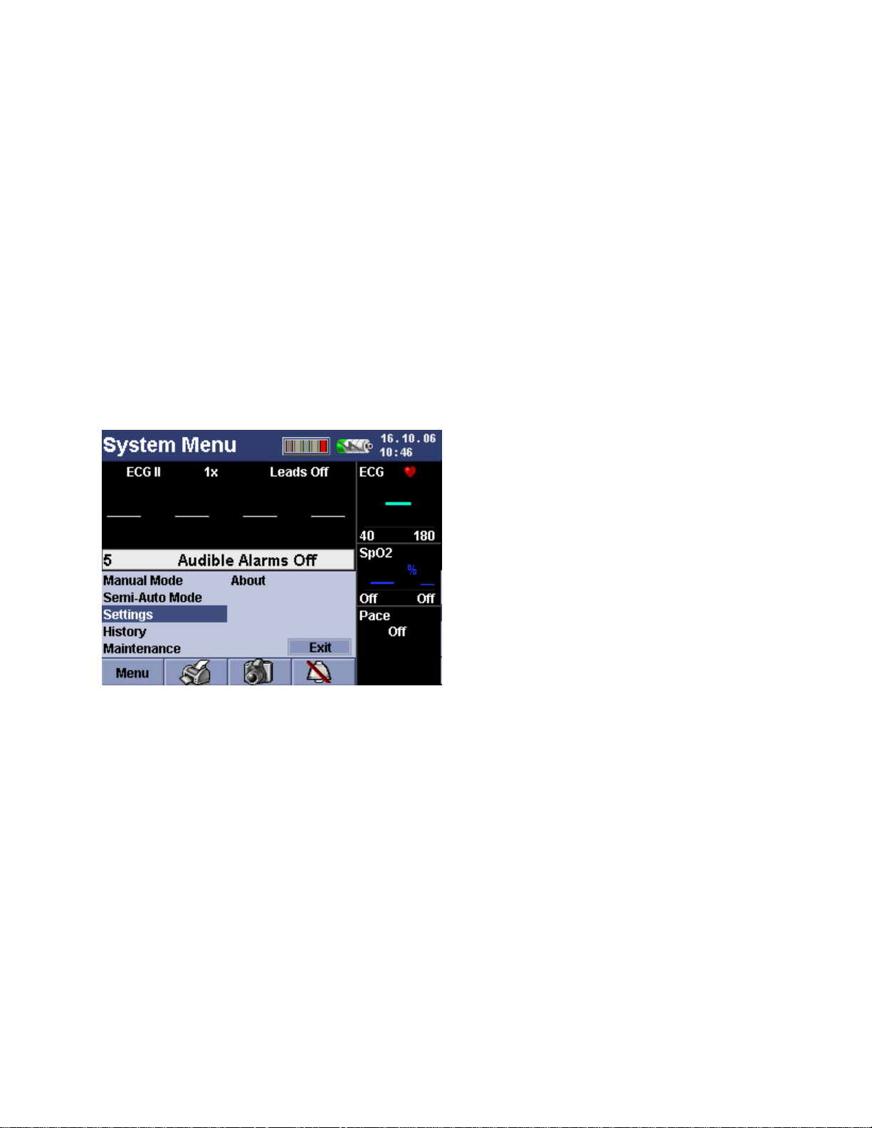
SETTINGS MENU
The Settings Menu allows customization to the Responder 2000 settings, which means that they are retained in memory
and are activated automatically when you power on the device.
The Settings Menu allows you to make adjustments to view the following settings.
The followings menu selections are available from the Settings menu.
• Defibrillation Settings
• Pacing Settings
• Channel Settings
• Alarms/Sounds Settings
• Date/Time Settings
• User Settings Menu
• System Settings Menu
PRECAUTION: Do not enter settings menu while connected to the patient.
TO VIEW THE SETTINGS MENU
From the Monitor screen,
1. Rotate the Rotary Selector Knob to the Menu.
2. Push the Rotary Selector Knob to open the System Menu
3. Rotate the Rotary Selector Knob to Settings
2026116-001 Revision B Responder™ 2000 Page 82
Page 83

TO VIEW THE SETTINGS MENU (CONTINUED)
4. Push the Rotary Selector Knob
5. A password may be required to change the settings.
6. To enter the password, push the Rotary Selector Knob. It will highlight the first space. There is no default password.
If a password needs to be reset, enter
VASCULAR.
2026116-001 Revision B Responder™ 2000 Page 83
Page 84

TO VIEW THE SETTINGS MENU (CONTINUED)
7. Push the Rotary Selector Knob and rotate the Rotary Selector Knob to scroll through the alphabet and numbers in
this field.
8. Push the Rotary Selector Knob when the letter you want is displayed. Repeat this for each space until the password
is complete.
9. When you are finished entering the password, turn the Rotary Selector Knob clockwise until the password box is
highlighted. Push the Rotary Selector Knob.
10. Turn the Rotary Selector Knob to Accept and push the Rotary Selector Knob.
11. After successfully entering the password, the Setting menu will now appear.
NOTE: To change the password, see TO CHANGE THE PASSWORD in this section of the manual.
NOTE: All changes to the settings of the Responder 2000 must be performed before connecting the Responder
2000 to the patient.
2026116-001 Revision B Responder™ 2000 Page 84
Page 85
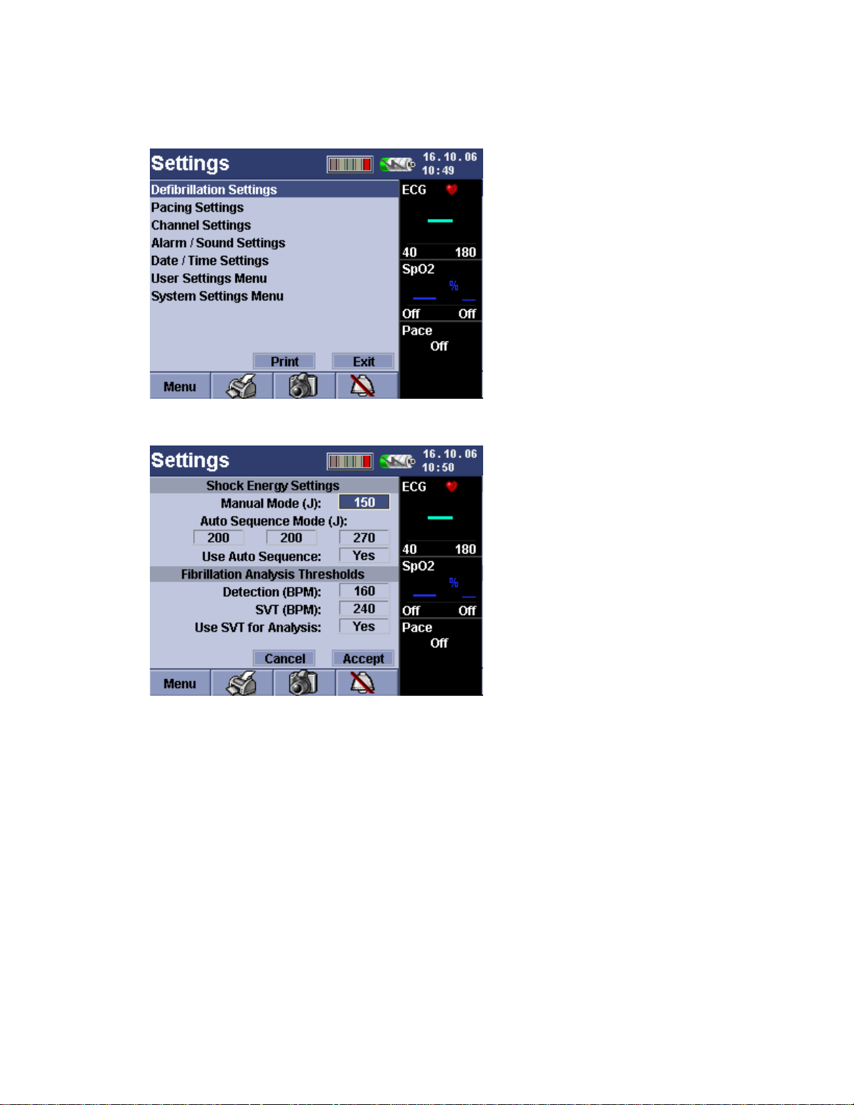
DEFIBRILLATION SETTINGS
The Responder 2000 Defibrillation Settings can be configured to the desired setting.
1. From the Settings menu, rotate the Rotary Selector Knob to Defibrillation Settings.
2. Push the Rotary Selector Knob to view Defibrillation Settings.
3. Turn the Rotary Selector Knob to highlight the desired setting.
4. Press the Rotary Selector Knob.
5. Turn the Rotary Selector Knob again to scroll through the settings and press to confirm the new value.
6. After selecting desired default settings, turn the Rotary Selector Knob to Accept.
7. Press the Rotary Selector Knob.
2026116-001 Revision B Responder™ 2000 Page 85
Page 86

DEFAULT SHOCK ENERGY SETTINGS
The Default Shock Energy Settings menu allows default settings to be selected for Manual Mode, Auto Sequence
Mode and Use Auto Sequence.
Manual Mode Auto Sequence Mode Use Auto Sequence Mode
Factory Default: 150 Joules
Available Settings: 2, 3, 5, 7,10,15,
20, 30, 50, 70, 100, 150, 200, 270
Joules
Factory Default: 200, 200, 270 Joules
Available Settings for first, second and
third shock: 2, 3, 5, 7, 10, 15, 20, 30,
50, 70, 100, 150, 200, 270 Joules
Factory Default: Yes
Available Settings: Yes or No
NOTE: The maximum energy for spoons is 50 joules.
FIBRILLATION ANALYSIS THRESHOLDS
The Fibrillation Analysis Thresholds menu allows default settings to be selected for Detection (B PM), SVT (BPM), and
Use SVT for analysis.
Detection (BPM) SVT (BPM) Use SVT for analysis
Factory Default: 160
Available Settings: 120 through 240 in
(increments of 5)
Factory Default: 240
Available Settings: 120 through 240
(increments of 5)
Factory Default: Yes
Available Settings: Yes or No
2026116-001 Revision B Responder™ 2000 Page 86
Page 87

PACING SETTINGS
The Responder 2000 Pacing settings can be configured to the desired setting from the Settings or Pacing mode box on
the startup menu. Pacing mode is turned off by default.
TO CHANGE PACING SETTINGS FROM SETTINGS MENU
1. From the Settings menu, rotate the Rotary Selector Knob to Pacing Settings and push Rotary Selector Knob to
select.
2. Select Pacing Default Parameters – Mode and Rate (PPM) by rotating Rotary Selector Knob to each setting. Push to
select setting, rotate to select option, and push to select desired default setting.
3. Rotate Rotary Selector Knob to Accept push to confirm settings.
2026116-001 Revision B Responder™ 2000 Page 87
Page 88

TO CHANGE SETTINGS FROM STARTUP MENU
1. From the startup menu, use Rotary Selector Knob to move focus to Pacing mode box in the bottom right hand side of
the menu.
2. Press the Rotary Selector knob to change the Pacing Settings.
3. After selecting the desired pacing mode, current, and rate settings, turn the selector knob to highlight the Pacing
mode box and press the rotary knob to confirm the settings.
4. Use Rotary Selector Knob to move focus to Pacing Mode Edit box and press Rotary Selector knob to select it.
PACING DEFAULT PARAMETERS
Mode Current Rate (PPM)
Factory Default: Demand
Available Settings: Demand, Fixed
Factory Default: 0 mA
Available Settings: 0 mA – 140mA
(increments of 5)
Factory Default: 60
Available Settings: 30 - 180
(increments of 5)
2026116-001 Revision B Responder™ 2000 Page 88
Page 89

CHANNEL SETTINGS
The Responder 2000 Channel Settings can be configured to the desired setting.
1. From the Settings menu, rotate the Rotary Selector Knob to Channel Settings.
2. Push the Rotary Selector Knob to view Channel Settings.
3. Turn the Rotary Selector Knob to highlight the desired setting.
4. Press the Rotary Selector Knob.
5. Turn the Rotary Selector Knob again to scroll through the settings and press to confirm the new value.
6. After selecting desired default settings, turn the Rotary Selector Knob to Accept.
7. Press the Rotary Selector Knob.
2026116-001 Revision B Responder™ 2000 Page 89
Page 90

CHANNEL 1
The Channel 1 menu allows default settings to be selected for Source and Gain.
Source Auto-switch Source
Factory Default: ECG II
Available Settings: ECG 1, ECG II, ECG III, aVR, aVF, aVL,
V, Paddles
Gain
Factory Default: 1x
Available Settings: .25x, 0.5x, 1x, 2x, 4x
Factory Default: Off
Available Settings: On, Off
CHANNEL 2
The Channel 2 menu allows default settings to be selected for Source and Gain.
Source Gain
Factory Default: SpO2 with Option, Otherwise Cascade
Available Settings: Cascade, SpO
2
Factory Default: 1x
Available Settings: .25x, 0.5x, 1x, 2x, 4x
FILTERS
The Filters menu allows default settings to be selected for Line Filter (Hz) and Muscle Filter.
Selection only valid for ECG channel, but not for pads/paddles channel.
Line Filter (Hz) Muscle Filter
Factory Default: Off
Available Settings: Off, 50, 60
Factory Default: On
Available Settings: On, Off
Always On, if pads/paddles selected.
2026116-001 Revision B Responder™ 2000 Page 90
Page 91

ALARMS/SOUND SETTINGS
The Responder 2000 Alarm/Sound Settings can be configured to the desired setting.
1. From the Settings menu, rotate the Rotary Selector Knob to Alarms/Sound Settings.
2. Push the Rotary Selector Knob to view Alarms/Sound Settings.
3. Turn the Rotary Selector Knob to highlight the desired setting.
4. Press the Rotary Selector Knob.
5. Turn the Rotary Selector Knob again to scroll through the settings and press to confirm the new value.
6. After selecting desired default settings, turn the Rotary Selector Knob to Accept.
7. Press the Rotary Selector Knob.
2026116-001 Revision B Responder™ 2000 Page 91
Page 92

AUDIO DEFAULTS
Audible Alarm Volume Pulse Beep
Factory Default: Off
Available Settings: On, Off
Factory Default: Loud
Available Settings: Soft, Medium,
Loud
Factory Default: Soft
Available Settings: Off, Soft,
Medium, Loud
PATIENT TRIGGERS
Low Heart Rate (BPM) High Heart Rate (BPM)
Factory Default: 40
Available Settings: Off, 25-120
(increments of 5)
Factory Default: 180
Available Settings: 40-300, Off
(increments of 5)
Low SpO2 Sat (%) High SpO2 Sat (%)
Factory Default: Off
Available Settings: Off, 81-98%
(increments of 1)
Factory Default: Off
Available Settings: 95-100%, Off
(increments of 1)
2026116-001 Revision B Responder™ 2000 Page 92
Page 93

DATE/TIME SETTINGS
The Responder 2000 time, date, and date format can be configured to the desired setting.
1. From the Settings menu, rotate the Rotary Selector Knob to Date/Time Settings.
2. Press the Rotary Selector Knob to select Date/Time Settings.
3. The Date/Time Settings screen will be displayed.
4. For each setting, rotate the Rotary Selector Knob clockwise and counterclockwise to select the desired value.
5. Push the Rotary Selector Knob to select desired setting.
6. To save the time, date, and date format settings, rotate Rotary Selector Knob to Accept and push.
2026116-001 Revision B Responder™ 2000 Page 93
Page 94

TIME SETTINGS DATE SETTINGS
Hour format: HH Hour
Value: 00 through 23
Minute Format: MM Minute
Value: 00 through 59
Time Format: AM/PM, 24
Hour
Default Time Format: 24
Hour
Date format: DD Date Value: 1 through 31
Month Format: MM Month Value: 01 through 12
01 January 04 April 07 July 10 October
02 February 05 May 08 August 11 November
03 March 06 June 09 September 12 December
Year format: YY Year Value: 04 through 99
Date Format:
Month/Day/Year, Year/Month/Day, Day.Month.Year
Default Date Format: Day.Month.Year
NOTE: The Responder 2000 does not automatically adjust the
Date/Time for Daylight Savings.
2026116-001 Revision B Responder™ 2000 Page 94
Page 95

USER SETTINGS MENU
The Responder 2000 User Settings Menu allows you to store the name of your institution in the device and create a new
password.
1. From the Settings menu, rotate the Rotary Selector Knob to User Settings Menu.
2. Push the Rotary Selector Knob to view User Settings Menu.
3. Turn the Rotary Selector Knob to highlight the desired setting.
4. Press the Rotary Selector Knob.
5. Turn the Rotary Selector Knob to select Facility or Set Password.
6. Press the Rotary Selector Knob.
7. After setting up System Settings, Select Exit to go back to main screen, or Back then the Rotary Selector Knob to go
back to the System Settings menu.
2026116-001 Revision B Responder™ 2000 Page 95
Page 96

FACILITY
The Facility menu allows you to store the name of the institution in the device.
1. Push the Rotary Selector Knob to bring the cursor to the first space.
2. Push the Rotary Selector Knob again to select the letter, number, punctuation.
3. Turn the Rotary Selector Knob to scroll through the English only alphabet and numbers in this field.
4. Push the Rotary Selector Knob when the letter you want is displayed. Repeat this for each space until the name is
complete.
5. When you are finished entering the desired name, turn the Rotary Selector Knob clockwise until the name box is
highlighted. Push the Rotary Selector Knob.
6. Turn the Rotary Selector Knob to Accept and push the Rotary Selector Knob.
2026116-001 Revision B Responder™ 2000 Page 96
Page 97

SET PASSWORD
The Responder 2000 Set Password Menu allows you create a unique password.
There is no default password.
1. To open the Set Password menu, turn the Rotary Selector Knob to Set Password and press the Rotary Selector
Knob.
2. Push the Rotary Selector Knob to bring the cursor to the first space.
3. Push the Rotary Selector Knob again to select the letter or number.
4. Turn the Rotary Selector Knob to scroll through the English only alphabet and numbers in this field.
5. Push the Rotary Selector Knob when the letter you want is displayed. Repeat this for each space until the name is
complete.
6. When you are finished entering the desired password, turn the Rotary Selector Knob clockwise until the name box is
highlighted. Push the Rotary Selector Knob.
7. Re-enter the New Password again.
8. Turn the Rotary Selector Knob to Accept and push the Rotary Selector Knob.
9. When you are finished re-entering the password, turn the Rotary Selector Knob clockwise until the name box is
highlighted. Push the Rotary Selector Knob.
10. Turn the Rotary Selector Knob to Accept and push the Rotary Selector Knob.
2026116-001 Revision B Responder™ 2000 Page 97
Page 98

SYSTEM SETTINGS MENU
The Responder 2000 System Settings menu allows you to configure display, printer, power-up settings as well as
restoring Responder 2000 defaults.
1. From the Settings menu, rotate the Rotary Selector Knob to System Settings Menu.
2. Push the Rotary Selector Knob to view System Settings Menu.
3. Turn the Rotary Selector Knob to highlight the desired setting.
4. Press the Rotary Selector Knob.
5. Turn the Rotary Selector Knob to select Display Settings, Printer Settings, Power-Up Settings, or Restore
Defaults.
6. Press the Rotary Selector Knob.
7. After setting up System Settings, Select Exit to enter Monitor Mode or Back to back to System Settings menu.
2026116-001 Revision B Responder™ 2000 Page 98
Page 99

DISPLAY SETTINGS
The Responder 2000 Display Settings menu allows you to configure the backlight of the graphics display.
1. From the Settings menu, rotate the Rotary Selector Knob to Display Settings
2. Push the Rotary Selector Knob to view Display Settings settings.
2026116-001 Revision B Responder™ 2000 Page 99
Page 100

DISPLAY SETTINGS (CONTINUED)
3. Turn the Rotary Selector Knob to select the desired value.
Default Value: Bright
Available Settings:Dim, Medium, Bright
4. After selecting desired setting, push the Rotary Selector Knob.
5. Turn the Rotary Selector Knob to Accept.
6. Press the Rotary Selector Knob.
2026116-001 Revision B Responder™ 2000 Page 100
 Loading...