

Page 1

Responder 1000/1100
Version V 1.0
Servicing Instructions
227 487 20 ENG Revision G
Page 2

GE Medical Systems
Information Technologies Responder 1000/1100 Page 2/38
Service Instructions
──────────────────────────────────────────────────────────────────
Caution:
During repairs/service interventions, observe the protective measures against damage due to ESD.
• GE Medical Systems Information Technologies GmbH is responsible for the effects on safety,
reliability, and performance of the device, only if
− assembly operations, extensions, readjustments, modifications, or repairs are carried out
by GE Medical Systems Information Technologies GmbH or by persons authorized by
GE Medical Systems Information Technologies GmbH,
− the electrical installation of the relevant room complies with the applicable national and
local requirements, and
− the instrument is used in accordance with the instructions for use.
• This manual contains service information, operating instructions are provided in the Operator’s
Manual of the instrument.
• This manual is in conformity with the instrument at printing date.
• All rights are reserved for instruments, circuits, techniques, and names appearing in the manual.
The authorized representative for GE Medical Systems Information Technologies Inc. in Europe
is:
GE Medical Systems Information Technologies GmbH
Munzinger Str. 3
D-79111 Freiburg, Germany
Tel. +49 (0) 7 61 45 43-0
Fax: +49 (0) 7 61 45 43-233
©
2006-2008 General Electric Company. All rights reserved.
227 487 20 Rev G
Page 3

GE Medical Systems
Information Technologies Responder 1000/1100 Page 3/38
Service Instructions
──────────────────────────────────────────────────────────────────
Contents
1 Documentation and nomenclature of GE Medical Systems instrument part Nos....................... 5
1.1 Configuration of Instrument part No..................................................................................... 5
1.2 Configuration of the PCB part No ........................................................................................ 5
1.3 Instrument Status Documentation (nominal status).............................................................. 6
2 General Overview ....................................................................................................................... 7
2.1 Responder 1000...................................................................................................................... 8
2.2 Responder 1100..................................................................................................................... 9
2.3 Block Diagram, total Unit................................................................................................... 10
2.4 Mechanical Structure .......................................................................................................... 11
2.5 Functions............................................................................................................................. 11
3 Interfaces................................................................................................................................... 12
3.1 Internal Interfaces................................................................................................................ 12
3.2 External Interfaces .............................................................................................................. 15
4 Adjustment and Performance Instruction.................................................................................. 16
5 Unit Test Functions................................................................................................................... 18
5.1 General................................................................................................................................ 18
5.2 Test Mode............................................................................................................................ 18
6 Repair Notes.............................................................................................................................. 20
6.1 Safety Notes ........................................................................................................................ 20
6.2 Component Replacement, Battery disposal ....................................................................... 20
7 Troubleshooting ........................................................................................................................ 21
8 Maintenance and Technical Inspection..................................................................................... 22
8.1 Testing Equipment ......................................................................................................... 22
8.2 Technical Inspection ...................................................................................................... 22
8.2.1 Visual Checks................................................................................................................ 22
8.2.2 Function Checks............................................................................................................ 23
8.3 Safety Analysis Test....................................................................................................... 25
8.3.1 General Information...................................................................................................... 25
8.3.2 Measuring of Leakage Current...................................................................................... 25
8.3.3 Enclosure Leakage Current........................................................................................... 26
8.3.4 Patient Leakage Current................................................................................................ 27
9 Technical Description ............................................................................................................... 28
10 Spare Part List..................................................................................................................... 31
11 Schematics........................................................................................................................... 38
227 487 20 Rev G
Page 4

GE Medical Systems
Information Technologies Responder 1000/1100 Page 4/38
Service Instructions
──────────────────────────────────────────────────────────────────
Revision History
Each page of this manual has the document number followed by a revision letter, located at the
bottom line of the page. This letter identifies the manual update level. The latest letter of the alphabet
corresponds to the most current revision of the document.
The revision history of this manual is summarized below.
Date Revision Comments
1998 - 07 A Initial release
2004 – 01 B ECO 075782
2006 – 06 C ECO 082042
2007 – 05 D ECO 087144
2007 – 12 E ECO 088330
2008 – 06 F ECO091141, Changes on page 33, 34.
Drawing 10116601-D02 rev.L replaced by rev.M
2008 – 12 G ECO093900, Battery disposal added on page 20.
227 487 20 Rev G
Page 5
GE Medical Systems
Information Technologies Responder 1000/1100 Page 5/38
Service Instructions
──────────────────────────────────────────────────────────────────
1 Documentation and nomenclature of GE Medical Systems Information Technologies instrument part Nos
1.1 Configuration of Instrument part No
The instrument part No comprises 8 digits, the first 6 digits determining the instrument type, the
last 2 digits the instrument version. The language is determined by configuration, thus having no
influence on the part No.
E.g. Instrument Type Version
Responder 1000, without battery, 230...240 V 101 166 01
Responder 1100, with battery, 230...240V 101 166 12
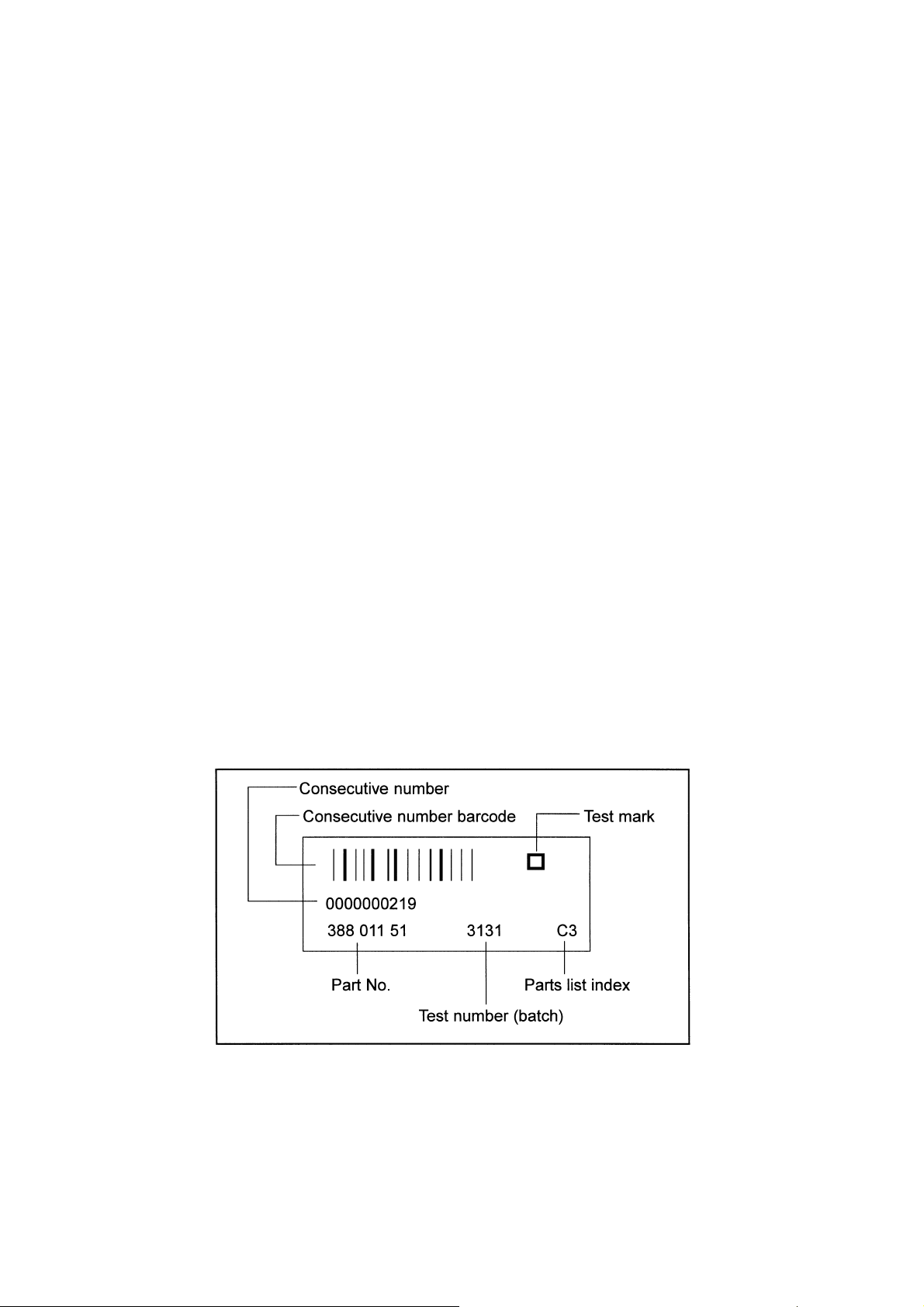
1.2 Configuration of the PCB part No
388 xxx yy Spare part numbers for the operative PCBs.
The instrument documentation, e.g., reference diagrams, circuit diagrams and parts lists are listed
under this part No.
The 388 number is located on the barcode label.
Configuration of the barcode labels:
227 487 20 Rev G
Page 6

GE Medical Systems
Information Technologies Responder 1000/1100 Page 6/38
Service Instructions
──────────────────────────────────────────────────────────────────
303 xxx yy Spare part numbers for PCBs tested especially thoroughly
303 numbers are only given to PCBs where the level of testing applied to 388 PCBs is inadequate for
implementation when servicing in the field, or where only a complete set of PCBs can be replaced in
the field.
In addition to a barcode label (388 number) 303 part Nos also have an additional label with a 303
number and are to be found in the spare parts list under this number.
389 xxx yy Replacement numbers for defective PCBs
Where servicing is required 389 PCBs are available for the replacement of some PCBs. When using a
replacement PCB (389 part No) the defective PCB is to be returned to the Freiburg factory.
Replacement PCB part Nos are included in the spare parts list.
389 PCBs have an additional adhesive label.
1.3 Instrument Status Documentation (nominal status)
Due to the hardware and software combination unambiguous documentation of the instrument
assembly status is necessary, also in the event of repairs.
This documentation comprises the following documents and measures:
Master Record Index (MRI)
This document is a component of this instrument documentation.
This document states the combination of permissible hardware and software for a particular
instrument version. The permissible PCB Index is given in the “Index” column with each update
delivered. Further permissible PCB Indexes are given in the “compatible” column. The PCB
Index can be found in the PCB barcode label.
Product Status Index
This document is created during manufacture. The Product Status Index documents the
hardware/software product status.
227 487 20 Rev G
Page 7

GE Medical Systems
Information Technologies Responder 1000/1100 Page 7/38
Service Instructions
──────────────────────────────────────────────────────────────────
2 General Overview
These service instructions describe both the Responder 1000 as well as the Responder 1100. Unless
a note appears to the contrary, this description applies to both units.
Responder 1000 and Responder 1100 are based on the same hardware platform.
The following versions are available:
101 166 01 Responder 1000, w/o battery, 230...240V~
101 166 02 Responder 1000, w/ battery , 230...240V~
101 166 03 Responder 1000, w/o battery, US, 115...120V~
101 166 04 Responder 1000, w/ battery, US, 115...120V~
101 166 05 Responder 1000, w/o battery, MiniDef III, Esaote 230...240V~
101 166 06 Responder 1000, w/ battery, MiniDef III, Esaote 230...240V~
101 166 07 Responder 1000, w/o battery, 115...120V~
101 166 08 Responder 1000, w/ battery, 115...120V~
101 166 09 Responder 1000, w/o battery, US, 230...240V~
101 166 10 Responder 1000, w/ battery, US, 230...240V~
101 166 11 Responder 1100, w/o battery, 230...240V~
101 166 12 Responder 1100, w/ battery, 230...240V~
101 166 13 Responder 1100, w/o battery, US, 115...120V~
101 166 14 Responder 1100, w/ battery, US, 115...120V~
101 166 15 Responder 1100, w/o battery, MiniDef III, sync, , Esaote 230...240V~
101 166 16 Responder 1100, w/ battery, MiniDef III, sync, , Esaote 230...240V~
101 166 17 Responder 1100, w/o battery, 115...120V~
101 166 18 Responder 1100, w/ battery, 115...120V~
101 166 19 Responder 1100, w/o battery, US, 230...240V~
101 166 20 Responder 1100, w/ battery, US, 230...240V~
101 166 23 Responder 1000, w/o battery, 230...240V~, China
101 166 24 Responder 1000, w/ battery, 230...240V~, China
The hardware consists of the following function blocks:
- PCB Responder 1000/1100
- battery module including PCB battery module
- keypad
- defibrillator electrodes (paddles)
The following function blocks are implemented as PCBs.
- PCB Responder 1000/1100
- PCB battery module
The intended use, the functions available and operation of
Responder 1000/1100 are described in the instructions for use.
227 487 20 Rev G
Page 8
GE Medical Systems
Information Technologies Responder 1000/1100 Page 8/38
Service Instructions
──────────────────────────────────────────────────────────────────
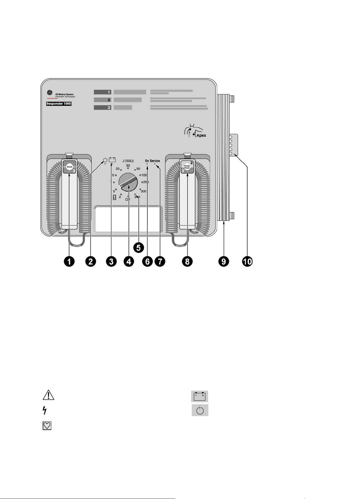
2.1 Responder 1000
1 Button to deliver the shock - together with button 8
2 AC line power indicator
3 Indicator light is green while the battery is charging (line power operation), it is red when the battery
needs charging (battery power operation)
4 Energy selector, On/Off switch
5 Indicators 2 to 360 illuminate when the corresponding energy level has been reached
6 "On" indicator illuminates when the device is On
7 "Service" indicator illuminates when a problem was detected during the automatic self-test
8 Button to initiate defibrillator charging and to deliver the shock - together with button 1
9 Power cord
10 Tube holder for skin prep cream
Explanation of symbols used on the device
Refer to Operator's Manual
Caution, High Voltage
Type CF signal input: highly insulated,
suitable for intracardiac application
battery
Standby mode (line power operation)
227 487 20 Rev G
Page 9
GE Medical Systems
Information Technologies Responder 1000/1100 Page 9/38
Service Instruction
───────────────────────────────────────────────────────────────────
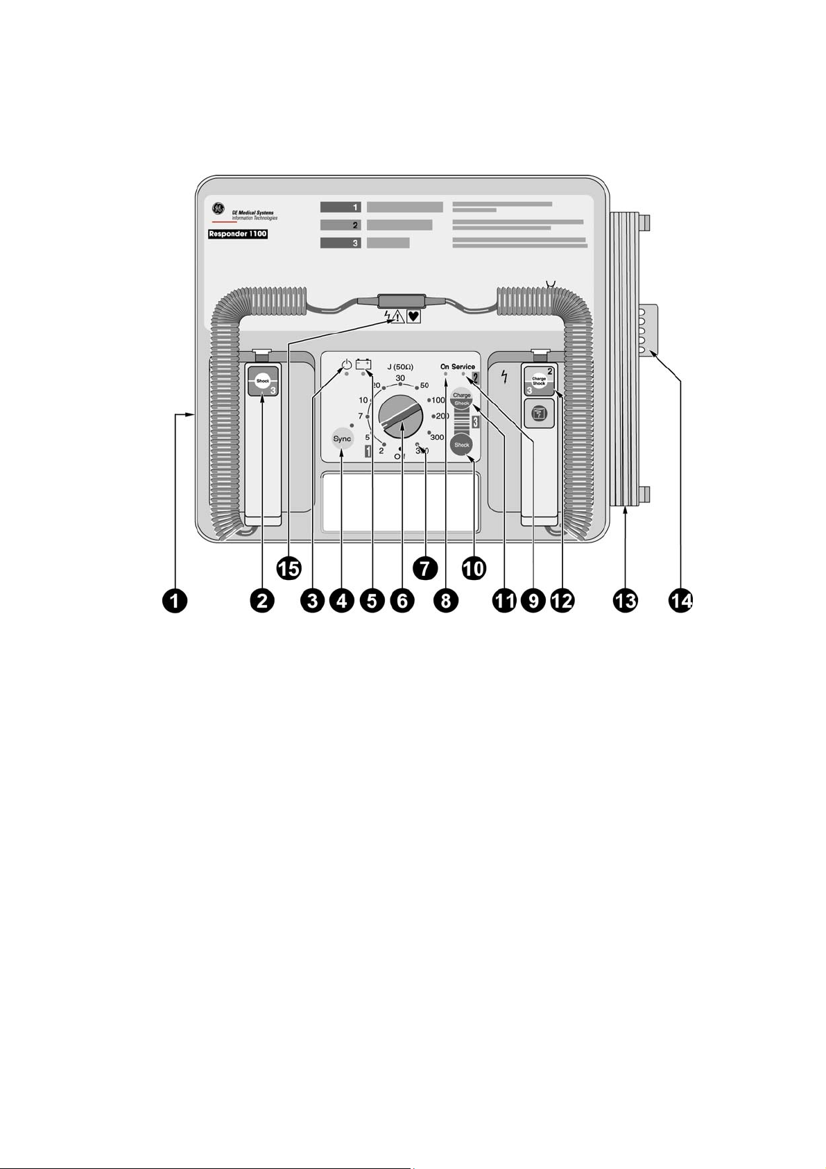
2.2 Responder 1100
1 ECG trigger signal input (synchronized defibrillation)
2 Button to deliver the shock - together with button 12
3 AC line power indicator
4 Button to enable and disable the synchronized defibrillation mode, with indicator (indicator
is illuminated during sync. defibrillation and flashes to the rhythm of the QRS complex)
5 Indicator light is green while the battery is charging (line power operation), it is red when
the battery needs charging (battery power operation)
6 Energy selector, On/Off switch
7 Indicators 2 to 360 illuminate when the corresponding energy level has been reached
8 "On" indicator illuminates when the unit is On
9 "Service" indicator illuminates when a problem was detected during the automatic self-test
10 Button to initiate defibrillator charging and to deliver the shock - together with button 11
when adhesive pads or internal electrodes are used
11 Button to deliver the shock when adhesive pads or internal electrodes are used - together
with button 10
12 Button to initiate defibrillator charging and to deliver the shock - together with button 2
13 Power cord
14 Tube holder for skin prep cream
15 Connector for defibrillation electrodes (turn off the unit before exchanging the electrodes)
227 487 20 Rev G
Page 10
GE Medical Systems
Information Technologies Responder 1000/1100 Page 10/38
Service Instruction
───────────────────────────────────────────────────────────────────
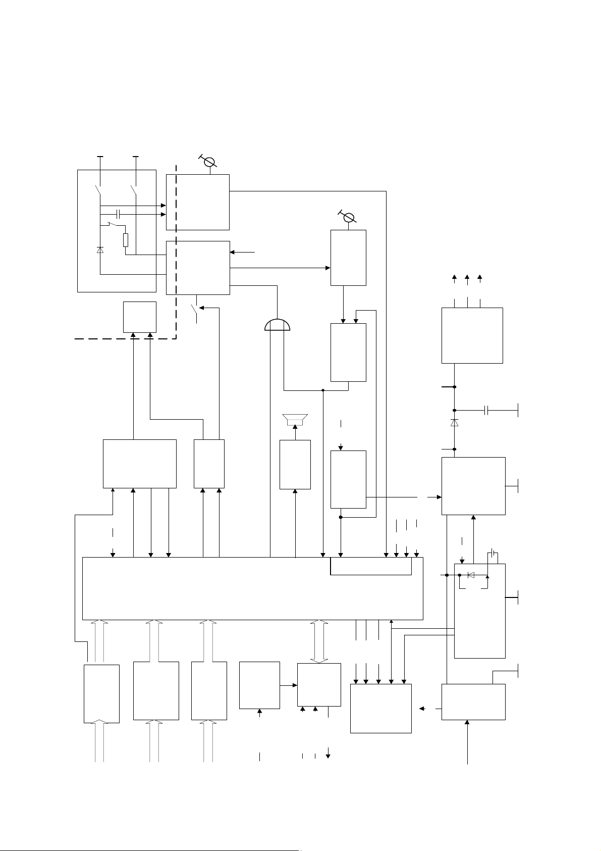
2.3 Block Diagram, total Unit
Defib-
electrodes
relay
shock
HV-Cap
voltage
conversion
relay
disarm
high-voltage part
HV-
relay
HV-
oscillator
Usec1
stop
Uref2
voltage
conversion
oscillator
ready
energy
indication
+12V
Vcc
Uref2
voltage
regulators
5 I/O
Vcc
Vdd
relay
shock
secure
3 I/O
paddlecode
relay
interface
2 I/O
device
control
audio
output
3 I/O
syncsignal
Uref2
energy
selection
serdata
off,2...360 J)
analog inputs
regCLK
serCLK
Vcc
Uref2
!= 0
MReset
Joule
Usec3
Usec2
Usec1
on/off logic
Vcc
Load
battery-
battery
charger
interface
pushbutton
pushbuttons keycode
227 487 20 Rev G
paddle
detection
paddle
model
detection
model varcode
QRS-
trigger
syncECG1V
sync
interface
syncdigital
syncableconn
power
LED
indication
marker
mainsLED
supply
mains
Page 11

GE Medical Systems
Information Technologies Responder 1000/1100 Page 11/38
Service Instruction
───────────────────────────────────────────────────────────────────
2.4 Mechanical Structure
The major mechanical components of the unit are the top and bottom shell. The top shell is the basic
element carrying the following sub-assemblies:
- PCB Responder 1000/1100
- Keypad (only Responder 1100)
The bottom shell holds the battery module and the capacitor which are linked to the PCB Responder
1000/1100 via cables.
The 6-pin inlet plug for connecting the sync-cable is located at the left side of the top shell. It is
linked to the PCB via a cable.
2.5 Functions
The functions follows the Block Diagram of the total unit in chapter 2.3 and the function blocks of
the P plans.
The unit contains following functions:
• power supply
• battery charger (located at PCB battery module)
• on/off logic
• voltage regulators
• device control
• LED indication
• audio output
• high voltage part
• shock relay secure
• relay interface
• HV- oscillator
• energy selection
• voltage conversion HV-Cap
• voltage conversion oscillator
• energy ready indication
227 487 20 Rev G
Page 12
GE Medical Systems
Information Technologies Responder 1000/1100 Page 12/38
Service Instruction
─────────────────────────────────────────────────────────────── ────
3 Interfaces nterfaces
3.1 Internal Interfaces 3.1 Internal Interfaces
Interface signal PCB Responder 1000/1100 Interface signal PCB Responder 1000/1100
connector : BattLoad1 connector : BattLoad1
function: connector to battery module
type: MODUI 6pol
signal name level active I/O meaning
1 Usec1 +18..30V - Output charging voltage
2 GND 0V - - Ground
3 +5V +5V - Output 5V
4 BATTMINIM +5V High Input battery Low signal
5 BATTCHARGE +18..25V - Input battery charge signal
6 BATTLEER - - Input battery empty signal
connector : Sync
function: connector to Sync input.
type: MODUII 6pol
signal name level active I/O meaning
1 ECG1V - Input 1V ECG
2 DIG_GND 0V - - digital Ground
3 SYNEXT L->H Input trigger signal extern monitors
4 MARKOUT High Output marker signal
5 AN_GND 0V - - analog Ground
6 SYNCABLE CMOS Low Input cable detection
connector : HV_Trafo_Pri
function: connector to High Voltage transformer
type: 4,8 x 0,8
signal name level active I/O meaning
2 HV_TRAFO_PRI/2 - - - "passive end" of transformer winding
1 HV_TRAFO_PRI/1 - - - "active end" of transformer winding
connector : HVCapConn
function: connector to High Voltage Capacitor
type: 4,8 x 0,8
signal name level active I/O meaning
- KO_PLUS - + - plus terminal
- KO_NEG - - - minus terminal
connector : KeyConn
function: connector to keypad
227 487 20 Rev G
Page 13
GE Medical Systems
Information Technologies Responder 1000/1100 Page 13/38
Service Instruction
───────────────────────────────────────────────────────────────────
type: TRIO MATE 4pol
signal name level active I/O meaning
1 SHOTAFOL_ +5V Low Input key “shock”
2 CHATAFOL_ +5V Low Input key “charge/shock
3 SYNTAFOL_ +5V Low Input key “sync”
4 GND 0 - Output Ground
connector : PaddConn1
function: connector to “Sternum” Paddle
type: MODU II 4pol
signal name level active I/O meaning
1 SHOTAPAD +5V High Input key “shock” (paddle)
2 VCC +5V - Output VCC
3 PADTYP0 +5V High Input paddle detection
4 PADTYPHE2 analog Input paddle detection (level depends on paddle type)
connector : PaddConn2
function: connector to “Apex” paddle
type: MODU II 4pol
signal name level active I/O meaning
1 NC
2 NC
3 CHATAPAD +5V High Input key charge/shock (paddle)
4 VCC +5V - Output VCC
connector : PaddleHVConn
function: connector to paddles (high voltage)
type: 4,8 x 0,8
signal name level active I/O meaning
7 HV_POS 5kV - Output connection to “Sternum” paddle
8 HV_NEG 0V - Output connection to “Apex” paddle
227 487 20 Rev G
Page 14
GE Medical Systems
Information Technologies Responder 1000/1100 Page 14/38
Service Instruction
───────────────────────────────────────────────────────────────────
Interface signal PCB battery module
connector : BattConn
function: connector to battery
type: soldering connection
signal name level active I/O meaning
1 BAT_PLUS 18V - - battery +
2 BAT_MINUS GND - - battery -
connector : BattLoad2
function: connection to PCB Responder 1000/1100
type: crimp connection terminal mini 2000
signal name level active I/O meaning
1 Usec1 +18..30V - Input charging voltage or battery voltage
2 GND 0V - Input Ground
3 +5V +5V - Input 5V
4 BATTMINIM +5V High Output battery Low signal
5 BATTCHARGE +18..25V High Output battery charge signal
6 BATTLEER - - Output battery empty signal
227 487 20 Rev G
Page 15
GE Medical Systems
Information Technologies Responder 1000/1100 Page 15/38
Service Instruction
───────────────────────────────────────────────────────────────────
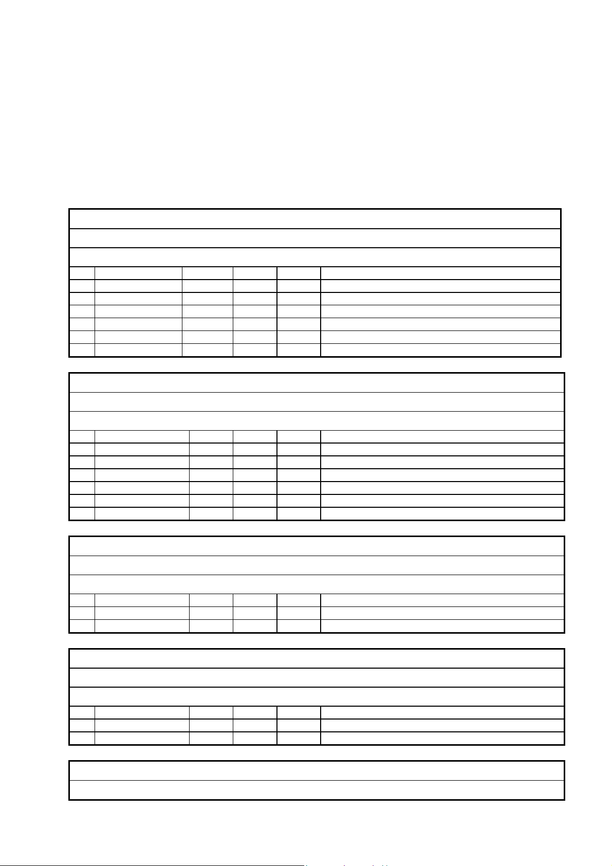
3.2 External Interfaces
Only the Responder 1100 is equipped with external interfaces.
Sync interface
1
2
3
1 1-Volt ECG signal, analog (see chapter 9 Technical Description)
2 Ground, digital
3 SYNC pulse, digital (see chapter 9 Technical Description)
4 Marker, digital
5 Ground, analog
6 SYNC cable detection
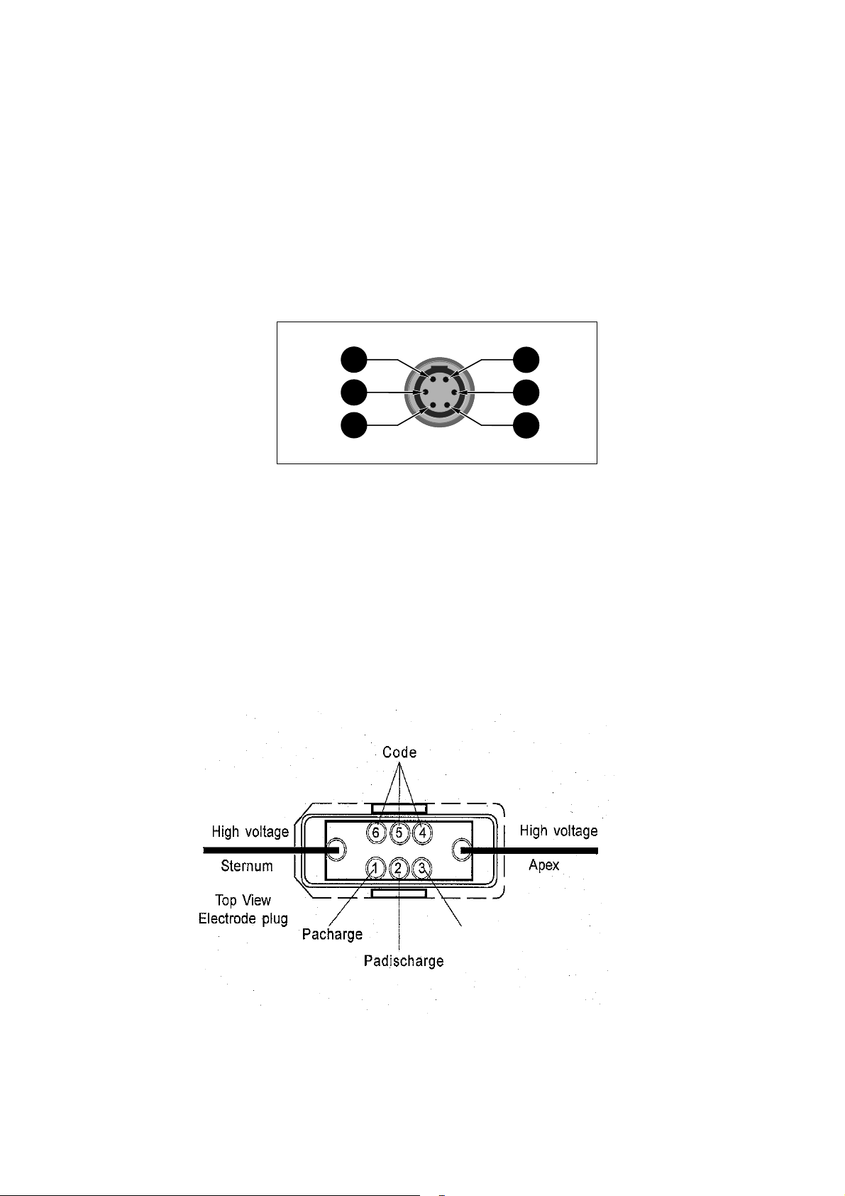
Interface for defibrillator electrodes
6
5
4
227 487 20 Rev G
N.C.
Page 16
GE Medical Systems
Information Technologies Responder 1000/1100 Page 16/38
Service Instruction
───────────────────────────────────────────────────────────────────
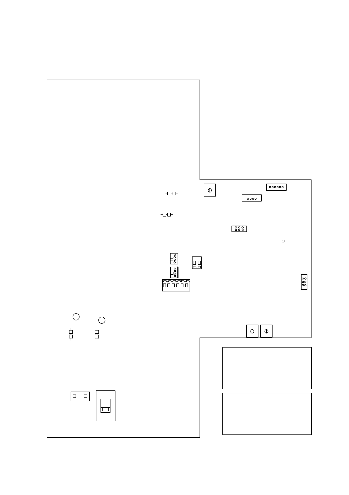
4 Adjustment and Performance Instruction
1
1-2
3-4
1
KEYCONN
5-6
SYNC
KOPOS (+)
R506
KONEG (-)
J2
LED500
HV_TRAFO_PRI
PADCONN2
PADCONN1
BATTLOAD
2
PADDLENEG
1
PADDLEPOS
1
11
1
R502 R503
5-6
3-4
1-2
J3
J2
1-2 must set
3-4 must set
5-6 not set
1
MAINS
230V
J3
227 487 20 Rev G
115V
S500
1-2 not set
3-4 not set
5-6 Test Mode if set
Page 17

GE Medical Systems
Information Technologies Responder 1000/1100 Page 17/38
Service Instruction
───────────────────────────────────────────────────────────────────
Where
(e.g. PCB)
entire unit
entire unit
PCB
Responder
PCB
Responder
PCB
Responder
entire unit
entire unit
What
(e.g. PCB)
check 30s
safety period
check 60s
safety period as
of “energy
reached”
adjust
oscillating
current
adjust energy
adjust charge
monitor LED
check charge
monitor LED’s
check charging
period
What to
measure with?
stopwatch
stopwatch
effective value
(RMS)
Ampere-meter
defibrillatortester
LED 500
all charge
monitor LED’s
stopwatch
Where to
clip to?
---
---
power
supply,
primary side,
(connector
mains)
paddles
---
---
---
Where to
turn
---
---
R 502
R 503
R 506
---
---
How much and
exact?
30 ± 1s until
defibrillator
deactivate charging
40...90 s ± 1s after
the defibrillator is
charged, it must
discharge internally
502...528mA
1004...1056mA
339...381J
as of “energy
reached” set R 506 so
that LED 500 just
lights up and after a
short time (2...3s)
goes out again
all LED’s must light
≤ 12s
What else to note?
remove plug
HV_TRAFO_PRI,
set energy to 2J,
press charge
button
set energy to 2J,
press charge
button
without battery,
charging with
energy set to 300J
U=230VAC,
U=115VAC
set energy to 360J,
trigger defibrillator
before this, the
energy level must
be adjusted with R
503.
set energy to 360J,
press charge
button
set energy to 360J,
press charge
button
without battery,
set energy to 360J,
press charge
button
227 487 20 Rev G
Page 18

GE Medical Systems
Information Technologies Responder 1000/1100 Page 18/38
Service Instruction
───────────────────────────────────────────────────────────────────
5 Unit T est Functions
5.1 General
After power-up and during operation, the Responder 1000/1100 runs automatic self-tests.
After power-up, the device beeps and all LED’s will briefly light up.
When the unit detects a error, the "Service" LED lights up and an acoustic signal sounds.
Every three seconds the unit try’s a new restart and test whether the error still appears.
5.2 Test Mode
The test mode is activated by inserting a jumper on PCB Responder 1000/1100 (J3 5-6). In the test
mode, some LED’s of the energy levels (2J to 30J) will indicate any detected malfunction. The
table below lists all error codes and the corresponding explanations.
If the device detects a error, then:
1.) switch Off the device
2.) insert jumper J3 5-6 (use the jumper J2 3-4 for this test)
3.) switch On the device
After power up, the “Service” LED lights up, an acoustic signal sounds and the error code will
indicated by the LED’s of the energy levels. This mode is active until the device will switched
Off.
227 487 20 Rev G
Page 19

GE Medical Systems
Information Technologies Responder 1000/1100 Page 19/38
Service Instruction
───────────────────────────────────────────────────────────────────
Error codes and the corresponding explanations
LED
30J
LED
20J
LED
10J
LED
7J
LED
5J
LED
2J
Meaning What to do
- - - - - light key error test keypad and paddles
- - - - light - rotary switch error replace PCB
- - - - light light high voltage error replace PCB
- - - light - - disarm error (initialization) replace PCB
- - - light - light disarm error (running time) replace PCB
- - - light light - variant error check jumper J3
- light - - - - device control error (Z501) replace PCB
- light - - - light device control error (Z501) replace PCB
- light - - light - device control error (Z501) replace PCB
- light - - light light device control error (Z501) replace PCB
- light - light - - device control error (Z501) replace PCB
- light - light - light device control error (Z501) replace PCB
- light - light light - device control error (Z501) replace PCB
- light - light light light error high voltage to high check adjustment
- light light - - - rotary switch error replace PCB
- light light - - light device control error (Z501) replace PCB
- light light - light - error shock relay test keypad and paddles
- light light - light light device control error (Z501) replace PCB
light light light - - device control error (Z501) replace PCB
light light light - light signal error “pENROK” replace PCB
light light light light - signal error “pSRELACT” replace PCB
light light light light light device control error (Z501) replace PCB
light - - - - - error voltage Uref2 replace PCB
227 487 20 Rev G
Page 20

GE Medical Systems
Information Technologies Responder 1000/1100 Page 20/38
Service Instruction
───────────────────────────────────────────────────────────────────
6 Repair Notes
6.1 Safety Notes
WARNING !
Shock hazard. Always switch of the unit
and disconnect the power cord before
opening the unit. Do not reconnect the
power cord when the unit is open.
Shock hazard. Before replacing the
primary fuse inside the unit, always
switch off the unit and disconnect the
power cord.
WARNING !
When replacing electronic components, always implement ESD protection.
Return replacement PCBs only in ESD packaging.
Return defective or exhausted batteries to the factory for proper disposal.
6.2 Component Replacement
Opening the unit
Before opening the unit switch the instrument off and disconnect power cord plug. To open the
unit, remove the 7 attachment screws on the base of the unit, place top shell to the left next to the
instrument. When reassembling the unit, make sure that none of the cables are pinched.
Replacing the PCB
The PCB is located in the top shell. With the unit open, first disconnect the plug connections
KOPOS and KONEG to the HV-capacitor. Disconnect the plug connection BATTLOAD
(only if the unit is equipped with battery). Disconnect the plug connection PADDLENEG,
PADDLEPOS, PADCONN1 and PADCONN2 to the paddles. At the Responder 1100
disconnect the remaining plugs to the keypad (plug connection KEYCONN) and to the Sync
input (plug connection SYNC). Then remove the 12 attachment screws.
Replacing the battery module
The battery module is located in the bottom shell. With the unit open, first disconnect the plug
connection BATTLOAD to the PCB. Then remove the 4 attachment screws.
Caution: Use only original GE Medical Systems batteries (see chapter 11, Spare Parts List)
Return defective battery module to the factory for proper disposal.
227 487 20 Rev G
Page 21

GE Medical Systems
Information Technologies Responder 1000/1100 Page 21/38
Service Instruction
───────────────────────────────────────────────────────────────────
7 Troubleshooting
Unit cannot be switched on during line-power operating:
Green LED (AC line power indicator) fails to light up and unit cannot be switched on
- line power cord defective or not connected properly ?
- mains connection on PCB correctly ?
- primary fuse inside the unit defective ?
- input voltage selection (S500) in the correct position ?
if all items above are OK: Î PCB defective
Green LED (AC line power indicator) lights, unit still cannot be switched on
- input voltage selection (S500) in the correct position ?
if all items above are OK: Î PCB defective
Unit cannot be switched on during battery operation:
- battery charged ?
- plug connection BATTLOAD on PCB connected ?
- connect mains cord, green LED (power indicator) and green LED (battery indicator)
must light up and unit can be activated ? If not, see above.
- battery charge activated when connecting the mains cord ?
- After 10 minutes charging, disconnect the mains cord. Can unit be switched on ?
Î battery module defective or battery capacity too low
Battery does not charge:
- green LED (power indicator) and green LED (battery indicator) must light up
- Check connector BATTLOAD to battery module
- Check connection BATTPLUS and BATTMINUS at PCB battery module
if all items above are OK: Î PCB battery module or battery is defective
Error detected during self-test:
If an error is detected during the self-test, the red Service-LED lights and an acoustic signal
sounds. (see chapter 5. Unit Test Functions)
227 487 20 Rev G
Page 22

GE Medical Systems
Information Technologies Responder 1000/1100 Page 22/38
Service Instruction
───────────────────────────────────────────────────────────────────
8 Maintenance and Technical Inspection
8.1 Testing Equipment
defibrillator-tester
standard 1V-ECG signal generator
8.2 Technical Inspection
Caution!
The unit uses high voltage. The inspection should be referred to
independent persons with adequate training and experience.
The Technical inspections must be carried out once every year.
Note!
The following checks and tests must be carried out by personnel who are qualified to maintain this
equipment.
Note:
Check the operational safety and the functional safety of the unit using the following check lists.
They serve the experienced technician to check the appliance. The person carrying out checks and
inspections must be familiar with the operation of the unit as specified in the operating
instructions.
The test items are based on the following measuring and test equipment:
The tests should be carried out with customer´s accessories. This will ensure that any defective
accessories are automatically identified. If measuring and test equipment other than the above is
used, the test items and the tolerance values may have to be modified accordingly.
8.2.1 Visual Checks
Check unit and accessories to make sure that:
- internal fuse comply with the values specified by the manufacturer
- safety notices attached to the unit are readable
- the mechanical condition allows the continued use of the unit
- no pollution reducing the safety standards are found
The defibrillator electrodes as well as handles and holder recesses must be free of any cream
residue. The defibrillator electrodes, power cord and Sync cable should be checked for any visible
external damage to the insulation and strain relief.
227 487 20 Rev G
Page 23

GE Medical Systems
Information Technologies Responder 1000/1100 Page 23/38
Service Instruction
───────────────────────────────────────────────────────────────────
8.2.2 Function Checks
AC line power LED
Connect the unit to mains. The green LED (AC line power indicator) must light up.
Power-up
Switch the unit on with energy selector switch (turn rotary switch to the first position 2J). After
power-up and during operation, the Responder 1000/1100 runs automatic self-tests.
After power-up, the unit beeps and all LED’s will briefly light up. Afterwards the green “OnLED” lights up and the unit is ready. When the unit detects an error, the "Service" LED lights up
and an acoustic signal sounds. Every three seconds the unit try’s a new restart and test whether the
error still appears. (see chapter 6. Unit test functions)
Automatic defibrillator discharge after 60 sec
see chapter 4. Adjustment and Performance Instruction
Adjustment of charge current
see chapter 4. Adjustment and Performance Instruction
Adjustment of the charge monitor LED’s
see chapter 4. Adjustment and Performance Instruction
Adjustment of the energy
see chapter 4. Adjustment and Performance Instruction
Delivered energy
The paddles must be locked at the defibrillator-tester.
Prerequisite for the following test <energy 360 joules in 11 second>
The battery must be fully charged or the instrument must be connected to mains.
Switch instrument on. Switch energy selector to 360 joules. Start energy charge by pressing the
charge/shock key in the electrode handle. Energy must be available after approx. 11 second.
As soon as the charge operation is complete a acoustic signal sounds. Release the defibrillation
pulse with the charge/shock key and the shock key within the next 60 seconds.
Test all energy levels:
Select each energy level and start energy charge every time by pressing the charge/shock key in the
electrode handle. Check that all indicators (LED’s) light up one after the other up to the selected level.
After the device beeps (defibrillator is charged), release the Shock immediately.
The values (tolerance range) for the energy released is given in the table next page.
If an energy adjustment proves necessary, see chapter 4. Adjustment and Performance Instruction.
Energy selected Energy released
227 487 20 Rev G
Page 24

GE Medical Systems
Information Technologies Responder 1000/1100 Page 24/38
Service Instruction
───────────────────────────────────────────────────────────────────
2
5
7
10
20
30
50
100
200
300
360
1-3
4-6
6-8
8-12
18-22
28-32
47-53
93-107
185-215
278-322
333-387
Synchronized defibrillation
Connect the Sync-cable to the defibrillator. Use a standard 1V-ECG signal generator (connected
to Pin 1 and 5) or digital pulse (connected to Pin 3 and 2) to generate signals. Set energy selector
switch to any energy setting. Press the Sync key on the defibrillator. The Sync function should
now be indicated by the Sync LED. As soon as a correct trigger signal is available, the indicator
goes off with each trigger pulse.
The paddles must be locked at the defibrillator-tester. Start energy charge by pressing the
charge/shock key in the electrode handle. As soon as the charge operation is complete a acoustic
signal sounds. Press the charge/shock key and the shock key. Shock release is effected by the Rpeak of the beat. Afterwards, the Sync function is automatically reset.
Battery
Proper maintenance of NiCd batteries is essential and considerably promotes their proper
performance. Routine preventive maintenance should be carried out qualified service technicians
on a regular basis. If batteries are repeatedly partially discharged, the resulting “memory effect”
dramatically reduce the battery capacity. This effect can be efficiently minimized by regular
conditioning. If the capacity of a relatively new battery is drastically reduced, the battery must be
reconditioned by repeated charging and discharging.
Yearly Battery Maintenance (Conditioning) and Checks
1. Charge the battery for min. 14 hours. While charging, the green battery LED must light up.
2. Disconnect the unit from the power line and discharge fully charged battery. To do so,
discharge the battery by defibrillation into the defibrillator-tester.
3. Min. 20 defibrillation at 360 joules must be possible. If less, the battery is too old or
improperly maintained and should be replaced. The red battery LED must light up when
battery is almost discharged.
4. Recharge the battery. This will take 14 hours.
Rechargeable batteries require special maintenance and continued checks to assure their function
in emergency situations. If is normal for batteries of this type to selfdischarge when not in use.
Note : Batteries must be replaced every 3 years.
227 487 20 Rev G
Page 25

GE Medical Systems
Information Technologies Responder 1000/1100 Page 25/38
Service Instruction
───────────────────────────────────────────────────────────────────
8.3 Safety Analysis T est
8.3.1 General Information
The suggested Safety Analysis Test refer to the international Standard IEC 601-1.
The tests are generally performed with Safety Testers, on most of them, the measuring circuits
according IEC 601 are already implemented.
The tests which have to be performed are described generally, for the handling of your Safety
Tester follow the user manual.
The tests may be performed under normal ambient conditions of temperature, humidity and
pressure and with line voltage.
The leakage currents correspond to 110 % of rated voltage for the tested unit. Most Safety Testers
take this into account, otherwise the measured values have to be calculated.
Recommended test equipment
- Safety Tester for measurements according IEC 601.
- Testing connector for the following description.
8.3.2 Measuring of Leakage Current
To proceed the suggested measurements, the unit under test has to be separated from any
interconnection to a system. If the unit is part of a system, extended tests according IEC 601-1-1
have to be performed. The following diagram shows the needed Measuring Circuit [M] for leakage current. The reading in mV corresponds to uA (leakage current). The Safety Testers
generally work with this Measuring Circuit [M] and the displayed values are already converted to
leakage current.
227 487 20 Rev G
Page 26

GE Medical Systems
Information Technologies Responder 1000/1100 Page 26/38
Service Instruction
───────────────────────────────────────────────────────────────────
8.3.3 Enclosure Leakage Current
This test is performed to measure leakage current from chassis to ground during normal conditions
(N.C.) and single fault conditions (S.F.C.).
In any case, the leakage current is measured from any exposed conductive parts to ground, the unit
under test has to be switched on and off.
Connect the unit under test to your Safety Tester.
- During normal conditions (N.C.), referring to the electrical diagram, measurements have to
be done under following conditions:
* Polarity switch Norm and RVS
* GND switch n/a
* S1 closed
- During single fault conditions (S.F.C.), referring to the electrical diagram, the measurements
have to be done under following conditions:
* Polarity switch NORM and RVS
* GND switch n/a
* S1 open
Test has failed if the measured values are greater than:
N.C. S.F.C
100 μA 500 μA
300 μA (U.L. requirements)
Electrical diagram for Enclosure Leakage Current Test
227 487 20 Rev G
Page 27

GE Medical Systems
Information Technologies Responder 1000/1100 Page 27/38
Service Instruction
───────────────────────────────────────────────────────────────────
8.3.4 Patient Leakage Current
This test performs a leakage current test under single fault conditions (S.F.C.) dependent of
domestic power outlet with 115 or 230 V AC as source into the floating inputs.
The following signal have to be tested:
From paddles
In any case, the leakage current is measured from paddles of unit under test, to ground.
For testing the floating input from paddles, the test is measured on each defibrillator paddle.
Connect the unit under test to your Safety Tester.
- Referring to the electrical diagram, measurements have to be done under following conditions
* Polarity switch NORM and RVS
* GND switch GND closed
* S1 closed
Test has failed if the measured values are greater than 100 μA at defibrillator paddles.
Electrical Diagram for Patient Leakage Current Test
For protection of the person, the following values of resistor R may be used:
Type BF 22 kOhm (120 to 130 V)
47 kOhm (220 to 240 V)
Type CF 100 kOhm (220 to 240 V)
227 487 20 Rev G
Page 28

GE Medical Systems
Information Technologies Responder 1000/1100 Page 28/38
Service Instruction
───────────────────────────────────────────────────────────────────
9 Technical Description
The “Technical Description” section describes the technical data of the unit valid at the time
of printing
Operating mode
• Responder 1000, non-synchronized defibrillation
• Responder 1100, non-synchronized and synchronized defibrillation
Energy selection
• Selectable energy levels, energy to be delivered into a 50-ohm external resistance (max.
energy of 50 joules for internal defibrillation by Responder 1100)
2
5
7
10
20
30
50
100
200
300
360 joules
• possible deviation from selected energy less than deviations permitted by IEC regulations
Energy storage
By means of capacitor, capacitor is charged from the power line or from battery.
Typical capacitor charge time to energy level of 360 joules:
• at line voltage or from full charged battery: 11 s
at 90% of line voltage or from partially discharged battery: 12 s (15 s max.)
measured at least 5 minutes after 15 shocks of 360 joules each
• internal safety discharge (see Safety discharge)
• stored energy level indicated by LED's
• "charge done" indicated by buzzer
Defibrillation shock
Capacitor discharge via induction coil (damped serial resonant circuit), pulse shape resembling
sinusoidal halfwave with decay period
• pulse duration for an external resistance of 50 ohms approximately 4.2 ms, measured from
beginning of the pulse to the intersection of the zero line and the inflection point of the trailing
pulse edge
• in synchronized mode the defibrillation shock is released within 25 ms of the R-wave trigger
227 487 20 Rev G
Page 29

GE Medical Systems
Information Technologies Responder 1000/1100 Page 29/38
Service Instruction
───────────────────────────────────────────────────────────────────
Discharge circuit
• serial oscillating circuit with external resistance (patient)
• capacitance 35 µF
• inductance 45 mH
• equivalent resistance 10.7 ohms, in series with external resistance (patient)
Pulse output
isolated , no conductive connection to other parts of the circuit or the enclosure, test voltage
9 kV DC, open-circuit and short-circuit-proof, type CF according to IEC requirements
Safety discharge
Capacitor discharge via internal load resistance:
• when the defibrillation shock is not triggered within 60 s after charging
• when the defibrillation shock is triggered, but the discharge circuit is interrupted, after
approx. 0.2 s
• immediately when reducing or increasing the selected energy during or after charging
• when the selected energy is not reached, after 30 s
• in the event of technical malfunctions
Test features
• LED’s for unit status: line connected, power on and battery charging
• Automatic defibrillator test on power up with LED for error indication
Synchronization (Responder 1100)
In the SYNC mode and in conjunction with a monitor, the unit can be used for synchronized
defibrillation
Synchronization via the SYNC interface can be achieved in two ways:
• by SYNC signal from the monitor (SYNC-pulses) or
• by SYNC signal (analog 1-Volt ECG) derived from the 1V-ECG via QRS-Trigger
With digital SYNC pulses
• Shock release: rising edge
• Input trigger threshold: VIH = +2.2 V (min.)
VIL = +1.8 V (max.)
• Input voltage range (typ.): 0 to +5 V
• Input voltage (max.): +15 V
• Input impedance: 10 KΩ (min)
• Pulse width (min.): >1 ms
With analog "1-Volt ECG"
• Input amplitude (typ.): 1 V (1 V/mV)
• Input voltage range: +/- 4 V
• Input voltage (max.): ±15 V
• Input impedance (min.): 10 KΩ
227 487 20 Rev G
Page 30

GE Medical Systems
Information Technologies Responder 1000/1100 Page 30/38
Service Instruction
───────────────────────────────────────────────────────────────────
Digital marker output
The trigger signal can be checked on the monitor screen. For this purpose, the Responder 1100
supplies a marker signal. Some patient monitors (e.g. Eagle 3000/4000) use this signal to
superimpose the trigger signal on the ECG waveform.)
• output voltage VOH = 3.5V (min.) at 1 mA
VOL = 0.5 V (max.) at 1 mA
• input impedance (min.) 200 Ω nominal
• output current 25 mA (max.)
• pulse width (min.) >100 ms
Power
From the power line, design in compliance with protection class II requirements of IEC 601
Model for rated voltage of 230...240 V
• operating voltage range 207...264 V, 49 to 65 Hz
• rated current 0.5 A
Model for rated voltage of 115...120 V
• operating voltage range 104 to 132 V, 49 to 65 Hz
• rated current 1.0 A
Power for models with built-in rechargeable NiCd battery
• rated voltage 18 V
• rated capacity 600 mAh
• charging time for depleted battery approximately 14 hours, overcharge protection
• battery charging from built-in power supply also during line-power operation
• a new and fully charged battery powers the defibrillator for approximately 25 defibrillation
shocks of 360 joules each (into 50 ohms) (with new, full charged battery at least 25 shocks at
an ambient temperature of 20 °C / 68 °F)
Operational readiness
2 s after power up (incl. Automatic selftest)
Operating position
any
Ambient conditions
• Operation
Temperature between 0 and +40 °C
relative humidity between 10 and 95%, no condensation
atmospheric pressure between 700 and 1060 hPa
• Storage and transport
Temperature between -30 and +60 °C
relative humidity between 10 and 95%, no condensation
atmospheric pressure between 500 to 1060 hPa
227 487 20 Rev G
Page 31

GE Medical Systems
Information Technologies Responder 1000/1100 Page 31/38
Service Instruction
───────────────────────────────────────────────────────────────────
Dimensions
• width 332 mm (13 in.)
• depth 300 mm (11.8 in.)
• height 130 mm (5 in.)
Weight
• model without battery approximately 5.4 kg (11.0 lbs)
• model with battery approximately 5.8 kg (12.8 lbs)
10 Spare Part List Responder 1000 Version’s
Part Number Description
101 166 01 without Battery 230V-240V
101 166 02 with Battery 230V-240V
101 166 03 without Battery 115V-120V US
101 166 04 with Battery 115V-120V US
101 166 05 without Battery 230V-240V MiniDef III, Esaote
101 166 06 with Battery 230V-240V MiniDef III, Esaote
101 166 07 without Battery 115V-120V
101 166 08 with Battery 115V-120V
101 166 09 without Battery 230V-240V US
101 166 10 with Battery 230V-240V US
101 166 23 without Battery 230V-240V China
101 166 24 with Battery 230V-240V China
Responder 1100 Version’s
Part Number Description
101 166 11 without Battery 230V-240V
101 166 12 with Battery 230V-240V
101 166 13 without Battery 115V-120V US
101 166 14 with Battery 115V-120V US
101 166 15 without Battery 230V-240V MiniDef III, sync, Esaote
101 166 16 with Battery 230V-240V MiniDef III, sync, Esaote
101 166 17 without Battery 115V-120V
101 166 18 with Battery 115V-120V
101 166 19 without Battery 230V-240V US
101 166 20 with Battery 230V-240V US
227 487 20 Rev G
Page 32

GE Medical Systems
Information Technologies Responder 1000/1100 Page 32/38
Service Instruction
───────────────────────────────────────────────────────────────────
Operator's Manual Responder 1000
Part Number Description
227 487 01 Operator’s Manual German
227 487 02 Operator’s Manual English
227 487 03 Operator’s Manual French
227 487 04 Operator’s Manual USA
227 487 05 Operator’s Manual Italian
227 487 06 Operator’s Manual Spanish
227 487 07 Operator’s Manual Russian
227 487 08 Operator’s Manual Swedish
227 487 09 Operator’s Manual ESAOTE
227 487 10 Operator’s Manual Portuguese
227 487 16 Operator’s Manual Polish
227 487 17 Operator’s Manual Czech
227 487 21 Operator’s Manual Chinese
2033249-002 Operator’s Manual Estonian
2033249-003 Operator’s Manual Latvian
2033249-004 Operator’s Manual Lithuanian
Operator's Manual Responder 1100
Part Number Description
227 488 01 Operator’s Manual German
227 488 02 Operator’s Manual English
227 488 03 Operator’s Manual French
227 488 04 Operator’s Manual USA
227 488 05 Operator’s Manual Italian
227 488 06 Operator’s Manual Spanish
227 488 07 Operator’s Manual Russian
227 488 08 Operator’s Manual Swedish
227 488 09 Operator’s Manual ESAOTE
227 488 10 Operator’s Manual Portuguese
Service Manual
Part Number Description
227 487 20 Service Manual Responder 1000/1100
227 487 20 Rev G
Page 33

GE Medical Systems
Information Technologies Responder 1000/1100 Page 33/38
Service Instruction
───────────────────────────────────────────────────────────────────
Housing Parts
Part Number Description
432 525 32 Housing upper shell for Responder 1000
432 525 31 Housing upper shell for Responder 1100
432 519 81 snap spring for Defibrillator paddles
432 519 60 Housing lower shell for Responder 1000/1100
924 017 20 Device foot
Label for Housing upper shell Responder 1000 (Logo: GE marquette)
Part Number Description
430 520 12 German
430 520 17 English
430 520 18 French
430 520 23 Italian
430 520 25 Spanish
430 520 27 Russian
430 520 28 Swedish
430 520 32 Portuguese
430 520 99 Chinese
2037488-001 Polish
2037299-001 Lithuanian
2041048-001 Estonian
2041050-001 Hungarian
2041052-001 Latvian
Label for Housing upper shell Responder 1000 REMCO (EP700 Cardioline)
Part Number Description
430 520 51 Italian
Label for Housing upper shell Responder 1000 (Logo: marquette)
Part Number Description
430 520 13 English, U.S. version
Label for Housing upper shell Responder 1000 Minidef PRO (Logo: ESAOTE)
Part Number Description
430 520 14 Italian
227 487 20 Rev G
Page 34

GE Medical Systems
Information Technologies Responder 1000/1100 Page 34/38
Service Instruction
───────────────────────────────────────────────────────────────────
Label for Housing upper shell Responder 1100 (Logo: Marquette Hellige)
Part Number Description
430 520 09 German
430 520 19 English
430 520 20 French
430 520 24 Italian
430 520 26 Spanish
430 520 29 Russian
430 520 30 Swedish
430 520 33 Portuguese
Label for Housing upper shell Responder 1100 (Logo: marquette)
Part Number Description
430 520 20 English, U.S. version
Label for Housing upper shell Responder 1000 Minidef SYC (Logo: ESAOTE)
Part Number Description
430 520 11 Italian
Label for Housing lower shell Responder 1000/1100
Part Number Description
430 520 83 German
430 520 84 English
430 520 85 French
430 520 86 Italian
430 520 87 Spanish
430 520 88 Russian
430 520 89 Swedish
430 520 90 Portuguese
430 520 98 Chinese
430 521 01 Czech
2037489-001 Polish
2037300-001 Lithuanian
2041049-001 Estonian
2041051-001 Hungarian
2041053-001 Latvian
227 487 20 Rev G
Page 35

GE Medical Systems
Information Technologies Responder 1000/1100 Page 35/38
Service Instruction
───────────────────────────────────────────────────────────────────
Label for Housing lower shell Responder 1000
Part Number Description
2027555-001 WEEE label
2034056-020 China RoHS label
Keypad’s
Part Number Description
390 001 79 Keypad for Responder 1000 with Battery
390 001 80 Keypad for Responder 1000 without Battery
390 001 77 Keypad for Responder 1100 with Battery
390 001 78 Keypad for Responder 1100 without Battery
Connector`s
Part Number Description
383 273 86 Sync connector complete wired (Responder 1100)
383 272 24 Wire set for High voltage capacitor
303 446 64 Electrode coupling for Defibrillator paddles (Responder 1100)
Printed circuit board`s
Part Number Description
388 032 79 Spare PCB Responder 1000/1100
389 004 31 Exchange PCB Responder 1000/1100
Battery Part
Part Number Description
205 100 02 Battery Module complete
388 032 80 PCB Battery Module
383 273 72 Wire set Battery Module
504 654 54 Battery holder
929 165 31 Battery chargeable
227 487 20 Rev G
Page 36

GE Medical Systems
Information Technologies Responder 1000/1100 Page 36/38
Service Instruction
───────────────────────────────────────────────────────────────────
Miscellaneous Parts
Part Number Description
903 449 88 High voltage capacitor 35µF
482 035 21 Energy selector button
303 439 42 Mains cable
2031736-001 Power Cord China
217 338 01 Defib electrode Shock Sternum (Responder 1000)
217 338 02 Defib electrode Charge/Shock Apex (Responder 1000)
217 337 01 Defib electrode (Responder 1100)
303 439 96 Contact insert for Defib paddles
384 018 72 Accessories pan complete with housing foot and screw
223 428 01 Sync. cable with open end for Responder 1100
Sync. Cable to different Monitors
Part Number Description
223 428 01 Sync. Cable with open end for Responder 1100
223 428 02 Sync. Cable to Eagle 3000/4000, Solar 8000
223 428 03 Sync. Cable to Eagle 1000
223 428 04 Sync. Cable to Case 8000
Supplies for Responder 1000
Defibrillation external
Part Number Description
303 439 96 Contact plate for Defib electrodes 1pcs
303 439 95 Electrode adapter for children, 1pcs
Consumables
Part Number Description
217 083 05 Electrode cream,10 tubes/cs
217 083 18 Electrode cream,250 ml refill
217 083 14 Electrode cream,51 container
930 115 82 Dispenser,30ml
227 487 20 Rev G
Page 37

GE Medical Systems
Information Technologies Responder 1000/1100 Page 37/38
Service Instruction
───────────────────────────────────────────────────────────────────
Supplies for Responder 1100
Defibrillation external
Part Number Description
217 337 01 Defib electrode, external,
217 337 02 Defib electrode, external,
303 439 96 Contact plate for Defib electrodes, 1pcs
303 439 95 Electrode adapter for children, 1pcs
217 329 01 Defib electrode anterior-posterior
919 202 94 Defibrillator-Pacing electrode, adult, disposable, 1 pair
919 202 95 Defibrillator- Pacing electrode, children, disposable ,1pair
223 383 01 Adapter for 91920294 and 91920295
Defibrillation internal
Part Number Description
217 308 01 Pair of defib electrodes for internal defibrillation (w/o. contact insert)
384 013 19 Contact inserts (2), internal, for adults
384 013 20 Contact inserts (2), internal, for children
384 013 21 Contact inserts (2), internal, for babies
919 202 36 External counter electrode for internal defibrillation
Consumables
Part Number Description
217 083 05 Electrode cream, pkg. of 10 tubes
217 083 18 Electrode cream, 250-ml bottle, refillable
217 083 14 Electrode cream, 51 container
930 115 82 Dispenser pump
227 487 20 Rev G
Page 38

GE Medical Systems
Information Technologies Responder 1000/1100 Page 38/38
Service Instruction
───────────────────────────────────────────────────────────────────
11 Schematics
Circuit Diagrams
Mechanical Drawing Responder 1000 101 166 01/02, 07/08, 23/24
Mechanical Drawing Responder 1000 101 166 03/04, 09/10
Mechanical Drawing Responder 1100 101 166 11/12, 17/18
Mechanical Drawing Responder 1100 101 166 13/14, 19/20
Mechanical Drawing MiniDef III 101 166 15/16
Complete Wiring Diagram Responder 1000 101 166 01,02,05,06,07,08,23,24 Sheet 1
Complete Wiring Diagram Responder 1100 101 166 11...20 Sheet 1
Master Record Index 101 166 .. Sheet 2
PCB Responder 1000/1100 388 032 79 P Sheet 1...6
388 032 79 R Sheet 1...2
PCB Battery Module 388 032 80 P Sheet 1
388 032 80 R Sheet 1
Sync Cable Responder 1100 223 428 01
227 487 20 Rev G
Page 39

Page 40

Page 41

Page 42

Page 43

Page 44

Page 45

Page 46

Diese Tabelle definiert die gültigen Konfigurationen von : Responder 1000 Version 1
This table defines the valid configurations of : Responder 1000 Version 1
Component Part No. Rev. compatible (Service) in Device sw. rel.
Lpl Responder 1000/1100, PCB Responder 1000/1100 388 032 79 L D,E,F,G,H,I,J,K 01,02,05, V1.2
06,07,08,
22,23,24
Ersatzteil-Nr. , Spare Part No. 388 032 79
Austausch Nr. , Replacement No. 389 004 31
Batterie Modul , Battery Module 205 100 02 A 02,04,06,
08,22,24
Lpl Batterie Modul , PCB Battery Module 388 032 80 B 02,04,06,08
22,24
Paddle Defib Shock 217 338 01 D B, C 01,02,05,06,
07,08,22,23,24
Paddle Defib Charge / Shock 217 338 02 D B, C 01,02,05,06,
07,08,22,23,24
Defi Kondensator , Defib Capacitor 903 449 88 A2 A, A1 01,02,05,06,
07,08,22,23,24
Komponente Sachnummer Index kompatibel (Service) in Variante Sw.Rel.
GE Medical Systems IT GmbH
Munzinger Str. 3
D-79111 Freiburg
Master Record Index (MRI)
File Name
10116601-D07_SZ02
Dokument Bezeichnung – Document Description
doc schem dwg SZ02
Dokument Nr. – Document No.
10116601-D07
q 089876 Defib capacitor added 04.12.07 P.Fischer
p 082042 General reworked, Resp.1100 removed 21.06.06 P.Fischer
o 076243 Index von 388 032 79 auf L gesetzt 11.03.04 P.Fischer
n 074451 Index von 388 032 79 auf K gesetzt 19.08.03 P.Fischer
m 072696 Elektroden 217 338 .. von C nach D 14.01.03 B.Deimel
l 071347 Elektrodenpaar..01 v. B n. C,..02 v. C n.D 30.09.02 B.Deimel
Änd.Index
Rev. No.
Blatt Nr. – Page No.
SZ/02
Teil Bezeichnung – Part Description
Responder 1000
ECO No. Änderungsbeschreibung – Change Description Datum-Date Name
MRI
Format
A4
Entworfen-Drawn:
Geprüft-Approved:
Teil Nr. – Part No.
30.06.98 G.Kaltenb.
Electronical
in Agile
101 166 ..
© 1998, 2007 General Electric Company. All rights reserved. / Schutzvermerk nach DIN 34 beachten !
Page 47

Marquette Hellige GmbH
Not equipped in Version :
x1
38803279
x2
x3
x4
x5
Revision-No
063764 22.02.00/MSG
REVISIONS
Index
A
Date / Name
A03
DRAWN
APPROVED
ISSUED
D-79007 Freiburg
43367260
Date / Name
18.12.97/BNH
18.12.97/BNH
B. HAGER
388 032 79 - D02
SCHEMATIC
RESPONDER 1000/1100
/home/projects_b/f67260/design
Sheet:
16
of
[1997, 12, 2, 3]
Page 48

Marquette Hellige GmbH
Not equipped in Version :
x1
38803279
x2
x3
x4
x5
Revision-No
063764
067395
REVISIONS
Index
A
B
Date / Name
22.02.00/MSG
A03
DRAWN
APPROVED
ISSUED
D-79007 Freiburg
F67260
Date / Name
17.12.97/JFS05.07.01/TYR
17.12.97/JFS
J. SCHULER
388 032 79 - D03
SCHEMATIC
RESPONDER 1000/1100
/home/projects_b/f67260/design/power_supply
Sheet:
62
of
[1997, 12, 12, 6]
Page 49

GE Medical Systems
Information Technologies GmbH
Not equipped in Version :
x1
38803279
x2
x3
x4
x5
Revision-No
060448
063764
074451
REVISIONS
Index
A
B
C
Date / Name
23.06.98/MSG
22.02.00/MSG
13.08.03/TYR
A01
DRAWN
APPROVED
ISSUED
D-79111 Freiburg
Munzinger Str. 3
43367260
Date / Name
17.12.97/BNH
17.12.97/BNH
B. HAGER
388 032 79 - D04
SCHEMATIC
RESPONDER 1000/1100
Sheet:
of
36
DATE
DIR
Page 50

Marquette Hellige GmbH
Not equipped in Version :
x1
38803279
x2
x3
x4
x5
Revision-No
REVISIONS
Index
A
Date / Name
22.02.00/MSG063764
A03
DRAWN
APPROVED
ISSUED
D-79007 Freiburg
43367260
Date / Name
18.12.97/BNH
18.12.97/BNH
HAGER
388 032 79 - D05
SCHEMATIC
RESPONDER 1000/1100
/home/projects_b/f67260/design/control
Sheet:
64
of
[1997, 12, 8, 2]
Page 51

Marquette Hellige GmbH
Not equipped in Version :
x1
38803279
x2
x3
x4
x5
Revision-No
063764
067395
REVISIONS
Date / Name
Index
A
22.02.00/MSG
B
05.07.01/TYR 18.12.97/BNH
A03
DRAWN
APPROVED
ISSUED
D-79007 Freiburg
43367260
Date / Name
18.12.97/BNH
HAGER
388 032 79 - D06
SCHEMATIC
RESPONDER 1000/1100
/home/projects_b/f67260/design/output
Sheet:
6
5
of
[1997, 12, 2, 3]
Page 52

Marquette Hellige GmbH
Not equipped in Version :
x1
38803279
x2
x3
x4
x5
Revision-No
060448
063764
REVISIONS
Index
A
B
Date / Name
23.06.98/MSG
A03
DRAWN
APPROVED
ISSUED
D-79007 Freiburg
43367260
Date / Name
18.12.97/BNH22.02.00/MSG
18.12.97/BNH
B. HAGER
388 032 79 - D07
SCHEMATIC
RESPONDER 1000/1100
/home/projects_b/f67260/design/sync
Sheet:
66
of
[1997, 12, 11, 5]
Page 53

Page 54

Page 55

Marquette Hellige GmbH
Not equipped in Version :
x1
38803280
x2
x3
x4
x5
Revision-No
--
-065687
REVISIONS
Index
--
-A
Date / Name
07.04.98/MNS
15.05.98/MSG
19.10.00/MSG
A03
DRAWN
APPROVED
ISSUED
D-79007 Freiburg
F67261
Date / Name
19.01.98/MSG
19.01.98/JFS
SCHULER
38803280-D04
SCHEMATIC
BATTERY MODULE
Sheet:
11
of
/home/projects_b/f67261/design
[1998, 1, 13, 3]
Page 56

Page 57

Page 58

Page 59

Page 60

GE Medical Systems
Information Technologies, Inc.
8200 West Tower Avenue
Milwaukee, WI 53233 USA
Tel: +1 414 355 5000
1 800 558 5120 (US only)
Fax: +1 414 355 3790
www.gehealthcare.com
GE Medical Systems
Information Technologies, GmbH
Munzinger Straße 3-5
D-79111 Freiburg
Germany
Tel: +49 761 45 43 - 0
Fax: +49 761 45 43 - 233
Asia Headquarters:
GE (China) Co., Ltd.
No1 Huatuo Road,
Zhangjiang Hi-Tech Park Pudong,
Shanghai, P.R.China 201203
Tel: +86 21 38777888
Fax: +86 21 38777402
 Loading...