

Page 1

MAC® 1200
Operator’s Manual
Software Version 6
2012250-022 Revision B
Page 2

127(The information in this manual only applies to MAC 1200 software version 6. It does not apply to
earlier software versions. Due to continuing product innovation, specifications in this manual are subject to
change without notice.
Listed below are GE Med ica l Sy stem s Information Technologies trademarks. All other trademarks contained
herein are the property of their respective owners.
900 SC, ACCUSKETCH, AccuVision, APEX, AQUA-KNOT, ARCHIVIST, Autoseq, BABY MAC, C Qwik
Connect, CardioServ, CardioSmart, CardioSys, CardioWindow, CASE, CD TELEMETRY, CENTRA, CHART
GUARD, CINE 35, CORO, COROLAN, COROMETRICS, Corometrics Sensor Tip, CRG PLUS, DASH,
Digistore, Digital DATAQ, E for M, EAGLE, Event-Link, FMS 101B, FMS 111, HELLIGE, IMAGE STORE,
INTELLIMOTION, IQA, LASER SXP, MAC, MAC-LAB, MACTRODE, MANAGED USE, MARQUETTE,
MARQUETTE MAC, MARQUETTE MEDICAL SYSTEMS, MARQUETTE UNITY NETWORK, MARS,
MAX, MEDITEL, MEI, MEI in the circle logo, MEMOPORT, MEMOPORT C, MINISTORE, MINNOWS,
Monarch 8000, MULTI-LINK, MULTISCRIPTOR, MUSE, MUSE CV, Neo-Trak, NEUROSCRIPT,
OnlineABG, OXYMONITOR, Pres-R-Cuff, PRESSURE-SCRIBE, QMI, QS, Quantitative Medicine,
Quantitative Sentinel, RAC RAMS, RSVP, SAM, SEER, SILVERTRACE, SOLAR, SOLARVIEW, Spectra
400, Spectra-Overview, Spectra-Tel, ST GUARD, TRAM, TRAM-NET, TRAM-RAC, TRAMSCOPE, TRIM
KNOB, Trimline, UNION STATION, UNITY logo, UNITY NETWORK, Vari-X, Vari-X Cardiomatic,
VariCath, VARIDEX, VAS, and Vision Care Filter are trademarks of GE Medical Systems Information
Technologies registered in the United States Patent and Trademark Office.
12SL, 15SL, Access, AccuSpeak, ADVANTAGE, BAM, BODYTRODE, Cardiomatic, CardioSpeak, CD
TELEMETRY
Cumulus, Event-Link Nimbus, HI-RES, ICMMS, IMAGE VAULT, IMPACT.wf, INTER-LEAD, IQA,
LIFEWATCH, Managed Use, MARQUETTE PRISM, MARQUETTE
MicroSmart, MMS, MRT, MUSE CardioWindow, NST PRO, NAUTILUS, O
®
-LAN, CENTRALSCOPE, Corolation, EDIC, EK-Pro, Event-Link Cirrus, Event-Link
®
RESPONDER, MENTOR,
SENSOR, Octanet, OMRS, PHi-
2
Res, Premium, Prism, QUIK CONNECT V, QUICK CONNECT, QT Guard, SMART-PAC, SMARTLOOK,
Spiral Lok, S wee the art, UNITY, Univer s al, Wate r fa ll, and Walk mom ar e tra dema rks of GE Med ica l Syst ems
Information Technologies.
© GE Medical Systems Information Technologies, 2004. All rights reserved.
T-2 MAC 1200 Revision B
2012250-022 21 July 2004
Page 3

CE Marking Information
CE Marking Information
Compliance
The MAC 1200 bears the CE mark “CE-0459”, notified body GMED,
indicating its conformity with the provisions of the Council Directive 93/
42/EEC concerning medical devices and fulfills the essential
requirements of Annex I of this directive.
Any other directive(s) and all the standards the product complies to are
listed in the general information of the operator manual for the product
following this page.
The country of manufacture can be found on the equipment labeling.
The product is in radio-interference protection class A in accordance with
EN 55011.
The product complies with the requirements of standard EN 60601-1-2
“Electromagnetic Compatibility - Medical Electrical Equipment”.
Exceptions
The safety and effecti veness of this device has been ve rified against
previously distributed devices. Although all standards applicable to
presently marketed devices may not be appropriate for prior devices (i.e.
electromagnetic compatibility standards), this device will not impair the
safe and effective use of those previously distributed devices. See user’s
information.
The MAC 1200 EMC: Immunity Performance
Users should be aware of known RF sources, such as radio or TV
stations and hand-held or mobile two-way radios, and consider them
when installing a medical device or system.
Be aware that adding accessories or components, or modifying the
medical device or system may degrade the EMI performance. Consul t
with qualified personnel regarding changes to the system
configuration.
Revision B MAC 1200 CE-1
2012250-022
Page 4

General Information
CE Marking Information
The device is designed to comply with IEC 60601 requirements. It is
a protection class I device.
The CE mark covers only the accessories listed in t he chapter “Orde r
Information”.
The information contained in th is ma nual d escr ibes sof tware ve rsion
6.
CE-2 MAC 1200 Revision B
2012250-022
Page 5

Contents
1 The Basics . . . . . . . . . . . . . . . . . . . . . . . . . . . . . . . . . . . . . 1-1
About This Manual . . . . . . . . . . . . . . . . . . . . . . . . . . . . . . . . . . . . . . . . . . . . . . . . . . . 1-3
Revision History . . . . . . . . . . . . . . . . . . . . . . . . . . . . . . . . . . . . . . . . . . . . . . . . . . .1-3
Manual Purpose . . . . . . . . . . . . . . . . . . . . . . . . . . . . . . . . . . . . . . . . . . . . . . . . . . .1-3
MAC 1200 Resting ECG Analysis System Option Codes . . . . . . . . . . . . . . . . . . . 1-4
Intended Use and Functional Description . . . . . . . . . . . . . . . . . . . . . . . . . . . . . . .1-5
Intended Audience . . . . . . . . . . . . . . . . . . . . . . . . . . . . . . . . . . . . . . . . . . . . . . . . .1-7
Definitions . . . . . . . . . . . . . . . . . . . . . . . . . . . . . . . . . . . . . . . . . . . . . . . . . . . . . . .1-7
Illustrations and Names . . . . . . . . . . . . . . . . . . . . . . . . . . . . . . . . . . . . . . . . . . . . .1-7
Safety Information . . . . . . . . . . . . . . . . . . . . . . . . . . . . . . . . . . . . . . . . . . . . . . . . . . . 1-8
Definitions . . . . . . . . . . . . . . . . . . . . . . . . . . . . . . . . . . . . . . . . . . . . . . . . . . . . . . .1-9
Underwriters Laboratories, Inc. . . . . . . . . . . . . . . . . . . . . . . . . . . . . . . . . . . . . . .1-12
Biocompatibility . . . . . . . . . . . . . . . . . . . . . . . . . . . . . . . . . . . . . . . . . . . . . . . . . . . . 1-13
Literature . . . . . . . . . . . . . . . . . . . . . . . . . . . . . . . . . . . . . . . . . . . . . . . . . . . . . . . . . 1-13
Service Information . . . . . . . . . . . . . . . . . . . . . . . . . . . . . . . . . . . . . . . . . . . . . . . . . 1-14
Requirements . . . . . . . . . . . . . . . . . . . . . . . . . . . . . . . . . . . . . . . . . . . . . . . . . . . .1-14
2 Controls and Indicators . . . . . . . . . . . . . . . . . . . . . . . . . . 2-1
General Information . . . . . . . . . . . . . . . . . . . . . . . . . . . . . . . . . . . . . . . . . . . . . . . . . . 2-3
MAC 1200 Control Panels . . . . . . . . . . . . . . . . . . . . . . . . . . . . . . . . . . . . . . . . . . .2-3
MAC 1200 Keyboard . . . . . . . . . . . . . . . . . . . . . . . . . . . . . . . . . . . . . . . . . . . . . . .2-4
Symbols . . . . . . . . . . . . . . . . . . . . . . . . . . . . . . . . . . . . . . . . . . . . . . . . . . . . . . . . . . . 2-6
3 Operating and Performance Tests . . . . . . . . . . . . . . . . . 3-1
Power Supply . . . . . . . . . . . . . . . . . . . . . . . . . . . . . . . . . . . . . . . . . . . . . . . . . . . . . . . 3-3
Installation and Mains Connection . . . . . . . . . . . . . . . . . . . . . . . . . . . . . . . . . . . . . 3-4
Performance Check . . . . . . . . . . . . . . . . . . . . . . . . . . . . . . . . . . . . . . . . . . . . . . . . . . 3-5
Contrast Adjustment . . . . . . . . . . . . . . . . . . . . . . . . . . . . . . . . . . . . . . . . . . . . . . .3-6
System Setup . . . . . . . . . . . . . . . . . . . . . . . . . . . . . . . . . . . . . . . . . . . . . . . . . . . . . . . 3-7
Revision B MAC 1200 i
2012250-022
Page 6

Connecting Peripheral Equipment . . . . . . . . . . . . . . . . . . . . . . . . . . . . . . . . . . . . . . 3-9
4 Preparing for ECG Recording . . . . . . . . . . . . . . . . . . . . . 4-1
Connecting the Patient Cable . . . . . . . . . . . . . . . . . . . . . . . . . . . . . . . . . . . . . . . . . . 4-3
Electrode Application . . . . . . . . . . . . . . . . . . . . . . . . . . . . . . . . . . . . . . . . . . . . . . . . 4-4
Applying Plate (Limb) Electrodes . . . . . . . . . . . . . . . . . . . . . . . . . . . . . . . . . . . . . .4-5
Applying Suction Electrodes (Chest) . . . . . . . . . . . . . . . . . . . . . . . . . . . . . . . . . . .4-5
Electrode Placement for Standard Leads (l, II, III, aVR, aVL, aVF, V1...V6) . . . . .4-6
Artifact Due to Poor Electrode Application . . . . . . . . . . . . . . . . . . . . . . . . . . . . . . .4-8
Entering Patient Data . . . . . . . . . . . . . . . . . . . . . . . . . . . . . . . . . . . . . . . . . . . . . . . 4-10
New Patient . . . . . . . . . . . . . . . . . . . . . . . . . . . . . . . . . . . . . . . . . . . . . . . . . . . . .4-12
Last Name, First Name . . . . . . . . . . . . . . . . . . . . . . . . . . . . . . . . . . . . . . . . . . . .4-12
Date of Birth . . . . . . . . . . . . . . . . . . . . . . . . . . . . . . . . . . . . . . . . . . . . . . . . . . . . .4-12
Patient ID . . . . . . . . . . . . . . . . . . . . . . . . . . . . . . . . . . . . . . . . . . . . . . . . . . . . . . .4-12
Chest Pain . . . . . . . . . . . . . . . . . . . . . . . . . . . . . . . . . . . . . . . . . . . . . . . . . . . . . .4-13
Pacemaker . . . . . . . . . . . . . . . . . . . . . . . . . . . . . . . . . . . . . . . . . . . . . . . . . . . . . .4-13
Gender/Race . . . . . . . . . . . . . . . . . . . . . . . . . . . . . . . . . . . . . . . . . . . . . . . . . . . .4-13
Height/Weight . . . . . . . . . . . . . . . . . . . . . . . . . . . . . . . . . . . . . . . . . . . . . . . . . . .4-13
Systolic BP/Diastolic BP . . . . . . . . . . . . . . . . . . . . . . . . . . . . . . . . . . . . . . . . . . .4-13
Ordering Physician / Referring Physician / Technician . . . . . . . . . . . . . . . . . . . .4-14
Phone Number . . . . . . . . . . . . . . . . . . . . . . . . . . . . . . . . . . . . . . . . . . . . . . . . . . .4-14
Medication . . . . . . . . . . . . . . . . . . . . . . . . . . . . . . . . . . . . . . . . . . . . . . . . . . . . . .4-14
Comments . . . . . . . . . . . . . . . . . . . . . . . . . . . . . . . . . . . . . . . . . . . . . . . . . . . . . .4-14
ID Required . . . . . . . . . . . . . . . . . . . . . . . . . . . . . . . . . . . . . . . . . . . . . . . . . . . . .4-14
Secondary ID . . . . . . . . . . . . . . . . . . . . . . . . . . . . . . . . . . . . . . . . . . . . . . . . . . . .4-14
Secondary ID Required . . . . . . . . . . . . . . . . . . . . . . . . . . . . . . . . . . . . . . . . . . . .4-15
Last/First Name Required . . . . . . . . . . . . . . . . . . . . . . . . . . . . . . . . . . . . . . . . . .4-15
Location Number . . . . . . . . . . . . . . . . . . . . . . . . . . . . . . . . . . . . . . . . . . . . . . . . .4-15
Room . . . . . . . . . . . . . . . . . . . . . . . . . . . . . . . . . . . . . . . . . . . . . . . . . . . . . . . . . .4-15
Order Number . . . . . . . . . . . . . . . . . . . . . . . . . . . . . . . . . . . . . . . . . . . . . . . . . . .4-15
Prompts . . . . . . . . . . . . . . . . . . . . . . . . . . . . . . . . . . . . . . . . . . . . . . . . . . . . . . . .4-15
5 Recording in 12 Lead Mode . . . . . . . . . . . . . . . . . . . . . . . 5-1
General Information . . . . . . . . . . . . . . . . . . . . . . . . . . . . . . . . . . . . . . . . . . . . . . . . . . 5-3
Recording . . . . . . . . . . . . . . . . . . . . . . . . . . . . . . . . . . . . . . . . . . . . . . . . . . . . . . . . . . 5-5
The Storage Program . . . . . . . . . . . . . . . . . . . . . . . . . . . . . . . . . . . . . . . . . . . . . . . . 5-8
Report Formats . . . . . . . . . . . . . . . . . . . . . . . . . . . . . . . . . . . . . . . . . . . . . . . . . . . . 5-10
Detailed Results . . . . . . . . . . . . . . . . . . . . . . . . . . . . . . . . . . . . . . . . . . . . . . . . . .5-11
ECG Transmission . . . . . . . . . . . . . . . . . . . . . . . . . . . . . . . . . . . . . . . . . . . . . . . . . . 5-12
ii MAC 1200 Revision B
2012250-022
Page 7

General Considerations . . . . . . . . . . . . . . . . . . . . . . . . . . . . . . . . . . . . . . . . . . . .5-12
Transmission via Modem . . . . . . . . . . . . . . . . . . . . . . . . . . . . . . . . . . . . . . . . . . .5-12
Batch Transmission . . . . . . . . . . . . . . . . . . . . . . . . . . . . . . . . . . . . . . . . . . . . . . .5-15
Transmission Log . . . . . . . . . . . . . . . . . . . . . . . . . . . . . . . . . . . . . . . . . . . . . . . . .5-15
Transmitting Data to a MUSE CV System Via Modem . . . . . . . . . . . . . . . . . . . .5-16
Receiving Data . . . . . . . . . . . . . . . . . . . . . . . . . . . . . . . . . . . . . . . . . . . . . . . . . . .5-19
Cart to Cart Communication . . . . . . . . . . . . . . . . . . . . . . . . . . . . . . . . . . . . . . . .5-20
Modem Setup (for Modem Æ Other) . . . . . . . . . . . . . . . . . . . . . . . . . . . . . . . . . .5-20
Adjusting Measurement Points/QT Dispersion . . . . . . . . . . . . . . . . . . . . . . . . . . . 5-22
Global Measurement Points . . . . . . . . . . . . . . . . . . . . . . . . . . . . . . . . . . . . . . . . .5-22
Local T Offset Measurement Point/QT Dispersion . . . . . . . . . . . . . . . . . . . . . . .5-24
Brief Operating Instructions – 12 Lead Mode . . . . . . . . . . . . . . . . . . . . . . . . . . . . 5-26
6 Recording in 6 Lead Mode . . . . . . . . . . . . . . . . . . . . . . . . 6-1
General Information . . . . . . . . . . . . . . . . . . . . . . . . . . . . . . . . . . . . . . . . . . . . . . . . . . 6-3
Recording . . . . . . . . . . . . . . . . . . . . . . . . . . . . . . . . . . . . . . . . . . . . . . . . . . . . . . . . . . 6-4
7 Arrhythmia M ode Recording . . . . . . . . . . . . . . . . . . . . . . 7-1
General Information . . . . . . . . . . . . . . . . . . . . . . . . . . . . . . . . . . . . . . . . . . . . . . . . . . 7-3
Recording . . . . . . . . . . . . . . . . . . . . . . . . . . . . . . . . . . . . . . . . . . . . . . . . . . . . . . . . . . 7-5
During the Recording . . . . . . . . . . . . . . . . . . . . . . . . . . . . . . . . . . . . . . . . . . . . . . .7-6
Final Report . . . . . . . . . . . . . . . . . . . . . . . . . . . . . . . . . . . . . . . . . . . . . . . . . . . . . .7-8
8 Pacemaker Patients / Recording During Defibrillation . 8-1
Recording ECGs of Pacemaker Patients . . . . . . . . . . . . . . . . . . . . . . . . . . . . . . . . . 8-3
ECG Recording During Defibrillation . . . . . . . . . . . . . . . . . . . . . . . . . . . . . . . . . . . . 8-4
9 System Setup . . . . . . . . . . . . . . . . . . . . . . . . . . . . . . . . . . 9-1
General Information . . . . . . . . . . . . . . . . . . . . . . . . . . . . . . . . . . . . . . . . . . . . . . . . . . 9-3
12 Lead Mode . . . . . . . . . . . . . . . . . . . . . . . . . . . . . . . . . . . . . . . . . . . . . . . . . . . . . . . 9-5
Report Sequence . . . . . . . . . . . . . . . . . . . . . . . . . . . . . . . . . . . . . . . . . . . . . . . . . .9-5
Rhythm Leads . . . . . . . . . . . . . . . . . . . . . . . . . . . . . . . . . . . . . . . . . . . . . . . . . . . .9-5
Gain . . . . . . . . . . . . . . . . . . . . . . . . . . . . . . . . . . . . . . . . . . . . . . . . . . . . . . . . . . . .9-5
Revision B MAC 1200 iii
2012250-022
Page 8

Report Format . . . . . . . . . . . . . . . . . . . . . . . . . . . . . . . . . . . . . . . . . . . . . . . . . . . .9-5
Detailed Results . . . . . . . . . . . . . . . . . . . . . . . . . . . . . . . . . . . . . . . . . . . . . . . . . . .9-5
Continuous Rhythm . . . . . . . . . . . . . . . . . . . . . . . . . . . . . . . . . . . . . . . . . . . . . . . .9-6
Muscle Filter/AC Filter . . . . . . . . . . . . . . . . . . . . . . . . . . . . . . . . . . . . . . . . . . . . . .9-6
Muscle Filter Frequency . . . . . . . . . . . . . . . . . . . . . . . . . . . . . . . . . . . . . . . . . . . . .9-6
Manual Copy To . . . . . . . . . . . . . . . . . . . . . . . . . . . . . . . . . . . . . . . . . . . . . . . . . . .9-7
Number of Copies . . . . . . . . . . . . . . . . . . . . . . . . . . . . . . . . . . . . . . . . . . . . . . . . .9-7
Interpretation . . . . . . . . . . . . . . . . . . . . . . . . . . . . . . . . . . . . . . . . . . . . . . . . . . . . .9-7
Print Interpretation . . . . . . . . . . . . . . . . . . . . . . . . . . . . . . . . . . . . . . . . . . . . . . . . .9-7
Override Function [no] . . . . . . . . . . . . . . . . . . . . . . . . . . . . . . . . . . . . . . . . . . . . . .9-8
6 Lead Mode . . . . . . . . . . . . . . . . . . . . . . . . . . . . . . . . . . . . . . . . . . . . . . . . . . . . . . . . 9-9
Report Sequence . . . . . . . . . . . . . . . . . . . . . . . . . . . . . . . . . . . . . . . . . . . . . . . . . .9-9
Gain . . . . . . . . . . . . . . . . . . . . . . . . . . . . . . . . . . . . . . . . . . . . . . . . . . . . . . . . . . .9-10
Speed . . . . . . . . . . . . . . . . . . . . . . . . . . . . . . . . . . . . . . . . . . . . . . . . . . . . . . . . . .9-10
Muscle Filter/AC Filter . . . . . . . . . . . . . . . . . . . . . . . . . . . . . . . . . . . . . . . . . . . . .9-10
Muscle Filter Frequency . . . . . . . . . . . . . . . . . . . . . . . . . . . . . . . . . . . . . . . . . . . .9-10
Anti-Drift System (ADS) . . . . . . . . . . . . . . . . . . . . . . . . . . . . . . . . . . . . . . . . . . . .9-11
Auto Paper Feed . . . . . . . . . . . . . . . . . . . . . . . . . . . . . . . . . . . . . . . . . . . . . . . . .9-11
Arrhythmia Mode . . . . . . . . . . . . . . . . . . . . . . . . . . . . . . . . . . . . . . . . . . . . . . . . . . . 9-12
Report Sequence . . . . . . . . . . . . . . . . . . . . . . . . . . . . . . . . . . . . . . . . . . . . . . . . .9-12
Gain . . . . . . . . . . . . . . . . . . . . . . . . . . . . . . . . . . . . . . . . . . . . . . . . . . . . . . . . . . .9-12
Muscle Filter . . . . . . . . . . . . . . . . . . . . . . . . . . . . . . . . . . . . . . . . . . . . . . . . . . . . .9-12
AC Filter . . . . . . . . . . . . . . . . . . . . . . . . . . . . . . . . . . . . . . . . . . . . . . . . . . . . . . . .9-12
Muscle Filter Frequency . . . . . . . . . . . . . . . . . . . . . . . . . . . . . . . . . . . . . . . . . . . .9-13
Trend Recording . . . . . . . . . . . . . . . . . . . . . . . . . . . . . . . . . . . . . . . . . . . . . . . . .9-13
Arrhythmia Data . . . . . . . . . . . . . . . . . . . . . . . . . . . . . . . . . . . . . . . . . . . . . . . . . .9-13
Episodes . . . . . . . . . . . . . . . . . . . . . . . . . . . . . . . . . . . . . . . . . . . . . . . . . . . . . . .9-13
Pharma . . . . . . . . . . . . . . . . . . . . . . . . . . . . . . . . . . . . . . . . . . . . . . . . . . . . . . . . . . . 9-14
Patient Data Customization . . . . . . . . . . . . . . . . . . . . . . . . . . . . . . . . . . . . . . . . .9-14
Project Code . . . . . . . . . . . . . . . . . . . . . . . . . . . . . . . . . . . . . . . . . . . . . . . . . . . .9-15
Trial ID . . . . . . . . . . . . . . . . . . . . . . . . . . . . . . . . . . . . . . . . . . . . . . . . . . . . . . . . .9-15
Investigator ID . . . . . . . . . . . . . . . . . . . . . . . . . . . . . . . . . . . . . . . . . . . . . . . . . . .9-15
Visit Number . . . . . . . . . . . . . . . . . . . . . . . . . . . . . . . . . . . . . . . . . . . . . . . . . . . .9-16
Visit Type . . . . . . . . . . . . . . . . . . . . . . . . . . . . . . . . . . . . . . . . . . . . . . . . . . . . . . .9-16
Dose Type . . . . . . . . . . . . . . . . . . . . . . . . . . . . . . . . . . . . . . . . . . . . . . . . . . . . . .9-16
Extra Questions . . . . . . . . . . . . . . . . . . . . . . . . . . . . . . . . . . . . . . . . . . . . . . . . . .9-16
High Security . . . . . . . . . . . . . . . . . . . . . . . . . . . . . . . . . . . . . . . . . . . . . . . . . . . . . . 9-17
Device Password . . . . . . . . . . . . . . . . . . . . . . . . . . . . . . . . . . . . . . . . . . . . . . . . .9-17
Don’t Allow Record Edits . . . . . . . . . . . . . . . . . . . . . . . . . . . . . . . . . . . . . . . . . . .9-18
Delete Only After Transmission . . . . . . . . . . . . . . . . . . . . . . . . . . . . . . . . . . . . . .9-18
Force Technician Name . . . . . . . . . . . . . . . . . . . . . . . . . . . . . . . . . . . . . . . . . . . .9-19
System Setup . . . . . . . . . . . . . . . . . . . . . . . . . . . . . . . . . . . . . . . . . . . . . . . . . . . . . . 9-20
Ordering Physician/Referring Physician/Technician . . . . . . . . . . . . . . . . . . . . . .9-20
Institution Name . . . . . . . . . . . . . . . . . . . . . . . . . . . . . . . . . . . . . . . . . . . . . . . . . .9-20
Cart Number . . . . . . . . . . . . . . . . . . . . . . . . . . . . . . . . . . . . . . . . . . . . . . . . . . . .9-20
Site Number * . . . . . . . . . . . . . . . . . . . . . . . . . . . . . . . . . . . . . . . . . . . . . . . . . . .9-20
iv MAC 1200 Revision B
2012250-022
Page 9

Location* . . . . . . . . . . . . . . . . . . . . . . . . . . . . . . . . . . . . . . . . . . . . . . . . . . . . . . .9-21
Date/Time . . . . . . . . . . . . . . . . . . . . . . . . . . . . . . . . . . . . . . . . . . . . . . . . . . . . . .9-21
Lead Fail Beep . . . . . . . . . . . . . . . . . . . . . . . . . . . . . . . . . . . . . . . . . . . . . . . . . . .9-21
High HR Beep . . . . . . . . . . . . . . . . . . . . . . . . . . . . . . . . . . . . . . . . . . . . . . . . . . .9-21
Lead Labels . . . . . . . . . . . . . . . . . . . . . . . . . . . . . . . . . . . . . . . . . . . . . . . . . . . . .9-21
Pace Enhancement . . . . . . . . . . . . . . . . . . . . . . . . . . . . . . . . . . . . . . . . . . . . . . .9-21
Baseline Roll Filter . . . . . . . . . . . . . . . . . . . . . . . . . . . . . . . . . . . . . . . . . . . . . . . .9-21
Date . . . . . . . . . . . . . . . . . . . . . . . . . . . . . . . . . . . . . . . . . . . . . . . . . . . . . . . . . . .9-22
Time . . . . . . . . . . . . . . . . . . . . . . . . . . . . . . . . . . . . . . . . . . . . . . . . . . . . . . . . . . .9-22
Units . . . . . . . . . . . . . . . . . . . . . . . . . . . . . . . . . . . . . . . . . . . . . . . . . . . . . . . . . . .9-22
Mains . . . . . . . . . . . . . . . . . . . . . . . . . . . . . . . . . . . . . . . . . . . . . . . . . . . . . . . . . .9-22
LCD Light Off After . . . . . . . . . . . . . . . . . . . . . . . . . . . . . . . . . . . . . . . . . . . . . . . .9-22
Low Battery Beep . . . . . . . . . . . . . . . . . . . . . . . . . . . . . . . . . . . . . . . . . . . . . . . . .9-22
Default mode . . . . . . . . . . . . . . . . . . . . . . . . . . . . . . . . . . . . . . . . . . . . . . . . . . . .9-22
Language . . . . . . . . . . . . . . . . . . . . . . . . . . . . . . . . . . . . . . . . . . . . . . . . . . . . . . .9-22
Enable Password Protection . . . . . . . . . . . . . . . . . . . . . . . . . . . . . . . . . . . . . . . .9-23
Test Data . . . . . . . . . . . . . . . . . . . . . . . . . . . . . . . . . . . . . . . . . . . . . . . . . . . . . . .9-23
Restore Defaults . . . . . . . . . . . . . . . . . . . . . . . . . . . . . . . . . . . . . . . . . . . . . . . . .9-23
Print Setup Lists . . . . . . . . . . . . . . . . . . . . . . . . . . . . . . . . . . . . . . . . . . . . . . . . . .9-23
Transmission Log . . . . . . . . . . . . . . . . . . . . . . . . . . . . . . . . . . . . . . . . . . . . . . . . .9-24
Check Record Retxn . . . . . . . . . . . . . . . . . . . . . . . . . . . . . . . . . . . . . . . . . . . . . .9-24
Communication . . . . . . . . . . . . . . . . . . . . . . . . . . . . . . . . . . . . . . . . . . . . . . . . . . . . 9-25
Baud Rate (PC) . . . . . . . . . . . . . . . . . . . . . . . . . . . . . . . . . . . . . . . . . . . . . . . . . .9-25
Protocol . . . . . . . . . . . . . . . . . . . . . . . . . . . . . . . . . . . . . . . . . . . . . . . . . . . . . . . .9-25
Modem . . . . . . . . . . . . . . . . . . . . . . . . . . . . . . . . . . . . . . . . . . . . . . . . . . . . . . . . .9-25
PIN Dialing . . . . . . . . . . . . . . . . . . . . . . . . . . . . . . . . . . . . . . . . . . . . . . . . . . . . . .9-26
Patient Data Menu Setup . . . . . . . . . . . . . . . . . . . . . . . . . . . . . . . . . . . . . . . . . . . . . 9-27
Required Data Fields . . . . . . . . . . . . . . . . . . . . . . . . . . . . . . . . . . . . . . . . . . . . . .9-28
Extra Questions 1 to 4 . . . . . . . . . . . . . . . . . . . . . . . . . . . . . . . . . . . . . . . . . . . . .9-28
Option Code . . . . . . . . . . . . . . . . . . . . . . . . . . . . . . . . . . . . . . . . . . . . . . . . . . . . . . . 9-29
ECG Transmission via Modem . . . . . . . . . . . . . . . . . . . . . . . . . . . . . . . . . . . . . . . . 9-30
Selecting the Communication Protocol . . . . . . . . . . . . . . . . . . . . . . . . . . . . . . . .9-30
Direct ECG Transmission . . . . . . . . . . . . . . . . . . . . . . . . . . . . . . . . . . . . . . . . . . . . 9-31
Selecting the Communication Protocol . . . . . . . . . . . . . . . . . . . . . . . . . . . . . . . .9-31
10 Loading Chart Paper . . . . . . . . . . . . . . . . . . . . . . . . . . . . 10-1
Procedure . . . . . . . . . . . . . . . . . . . . . . . . . . . . . . . . . . . . . . . . . . . . . . . . . . . . . . . . . 10-3
End-of-Paper Indication . . . . . . . . . . . . . . . . . . . . . . . . . . . . . . . . . . . . . . . . . . . .10-5
Aging Stability . . . . . . . . . . . . . . . . . . . . . . . . . . . . . . . . . . . . . . . . . . . . . . . . . . .10-6
Revision B MAC 1200 v
2012250-022
Page 10

11 Cleaning, Disinfection and Maintenance . . . . . . . . . . . 11-1
Cleaning and Disinfecting the Recorder Housing . . . . . . . . . . . . . . . . . . . . . . . . 11-3
Cleaning and Disinfecting the Patient Cable . . . . . . . . . . . . . . . . . . . . . . . . . . . .11-3
Cleaning and Disinfecting the Electrodes . . . . . . . . . . . . . . . . . . . . . . . . . . . . . .11-3
Maintenance . . . . . . . . . . . . . . . . . . . . . . . . . . . . . . . . . . . . . . . . . . . . . . . . . . . . . . . 11-4
Checks Before Each Use . . . . . . . . . . . . . . . . . . . . . . . . . . . . . . . . . . . . . . . . . . .11-4
Technical Inspections . . . . . . . . . . . . . . . . . . . . . . . . . . . . . . . . . . . . . . . . . . . . .11-4
Disposal . . . . . . . . . . . . . . . . . . . . . . . . . . . . . . . . . . . . . . . . . . . . . . . . . . . . . . . .11-4
12 Troubleshooting . . . . . . . . . . . . . . . . . . . . . . . . . . . . . . . 12-1
Troubleshooting Chart . . . . . . . . . . . . . . . . . . . . . . . . . . . . . . . . . . . . . . . . . . . . . . 12-3
13 Technical Specifications . . . . . . . . . . . . . . . . . . . . . . . . 13-1
Recording . . . . . . . . . . . . . . . . . . . . . . . . . . . . . . . . . . . . . . . . . . . . . . . . . . . . . . . . . 13-3
Printer Paper . . . . . . . . . . . . . . . . . . . . . . . . . . . . . . . . . . . . . . . . . . . . . . . . . . . .13-3
Paper Transport . . . . . . . . . . . . . . . . . . . . . . . . . . . . . . . . . . . . . . . . . . . . . . . . . .13-3
Membrane Keypad . . . . . . . . . . . . . . . . . . . . . . . . . . . . . . . . . . . . . . . . . . . . . . . .13-4
Display . . . . . . . . . . . . . . . . . . . . . . . . . . . . . . . . . . . . . . . . . . . . . . . . . . . . . . . . .13-4
Indicators (LEDs) . . . . . . . . . . . . . . . . . . . . . . . . . . . . . . . . . . . . . . . . . . . . . . . . .13-4
Lead Selection . . . . . . . . . . . . . . . . . . . . . . . . . . . . . . . . . . . . . . . . . . . . . . . . . . .13-4
Automatic Functions . . . . . . . . . . . . . . . . . . . . . . . . . . . . . . . . . . . . . . . . . . . . . .13-4
Detection of Pacer Pulses . . . . . . . . . . . . . . . . . . . . . . . . . . . . . . . . . . . . . . . . . .13-5
Heart Rate Indication . . . . . . . . . . . . . . . . . . . . . . . . . . . . . . . . . . . . . . . . . . . . . .13-5
Signal Inputs . . . . . . . . . . . . . . . . . . . . . . . . . . . . . . . . . . . . . . . . . . . . . . . . . . . .13-5
Data Interface . . . . . . . . . . . . . . . . . . . . . . . . . . . . . . . . . . . . . . . . . . . . . . . . . . .13-6
Transfer of ECGs . . . . . . . . . . . . . . . . . . . . . . . . . . . . . . . . . . . . . . . . . . . . . . . . .13-6
Receiving Data with the CSI Communication Protocol from the Following Units 13-6
Sending ECGs to the Following Units with the A5 Protocol . . . . . . . . . . . . . . . . .13-6
Remote Start (Hardware) . . . . . . . . . . . . . . . . . . . . . . . . . . . . . . . . . . . . . . . . . . .13-7
Signal Transmission . . . . . . . . . . . . . . . . . . . . . . . . . . . . . . . . . . . . . . . . . . . . . . .13-8
14 Order Information . . . . . . . . . . . . . . . . . . . . . . . . . . . . . . 14-1
General Information . . . . . . . . . . . . . . . . . . . . . . . . . . . . . . . . . . . . . . . . . . . . . . . . . 14-3
Options . . . . . . . . . . . . . . . . . . . . . . . . . . . . . . . . . . . . . . . . . . . . . . . . . . . . . . . . .14-3
General Accessories . . . . . . . . . . . . . . . . . . . . . . . . . . . . . . . . . . . . . . . . . . . . . .14-3
vi MAC 1200 Revision B
2012250-022
Page 11

Entering Special Characters . . . . . . . . . . . . . . . . . . . . . . .A-1
Special Characters . . . . . . . . . . . . . . . . . . . . . . . . . . . . . . . . . . . . . . . . . . . . . . . . . . A-3
Index . . . . . . . . . . . . . . . . . . . . . . . . . . . . . . . . . . . . . . . Index-1
Revision B MAC 1200 vii
2012250-022
Page 12

For your notes
viii MAC 1200 Revi sion B
2012250-022
Page 13

1 The Basics
Revision B MAC 1200 1-1
2012250-022
Page 14

For your notes
1-2 MAC 1200 Revision B
2012250-022
Page 15

About This Manual
Revision History
This manual has a revision letter, locate d at the bottom of each page.
This revision letter changes whenever t he manual is upd ated. Revisi on A
is the initial release of the document.
Manual Purpose
This manual describes the safe and effective operation of the MAC 1200
unit.
The Basics: About This Manual
Revision Date Comments
A 31 March 2003 Initial release of manual, describes version 6.0.
B 21 July 2004 Revised CE compliance information, High Security
“memory full” information added.
127(
This document describes the functionality of the U.S. interface for
the MAC 1200 unit.
Information in this manual differs from operating information for
MAC 1200 units developed for use internationally. Please refer to PN
2012250-021 for information on using the international interface.
Revision B MAC 1200 1-3
2012250-022
Page 16

The Basics: MAC 1200 Resting ECG Analysis System Option Codes
MAC 1200 Resting ECG Analysis System Option Codes
In addition to the software supplied with the unit, optional programs
may be purchased to upgrade the MAC 1200 performance features. In
order to use a new option, you need to activate it by entering the option
code number (refer to “Option Co de” on pag e 9-29 for details). The option
codes are entered into the MAC 1200 prior to shipping.
Software Package Functionality Option Code
MEAS Measurement (measurement of the 10-second resting ECG) _ _ _ _ _ _ _ _ _ _ _ _
DIAG Interpretation (interpretation of the 10-second resting ECG) _ _ _ _ _ _ _ _ _ _ _ _
MEMO Memory (storage of a maximum of 40 10-second resting ECGs) _ _ _ _ _ _ _ _ _ _ _ _
C100 Activates the three options MEAS, DIAG, MEMO for a maximum of 100 ECGs _ _ _ _ _ _ _ _ _ _ _ _
C500 Activates the three options MEAS, DIAG, MEMO for a maximum of 500 ECGs _ _ _ _ _ _ _ _ _ _ _ _
EVAL Activates the three options MEAS, DIAG, MEMO for a maximum of 4 weeks _ _ _ _ _ _ _ _ _ _ _ _
Serial No: _ _ _ _ _ _ _ _ _
1-4 MAC 1200 Revision B
2012250-022
Page 17

The Basics: MAC 1200 Resting ECG Analysis System Option Codes
Intended Use and Functional Description
The MAC 1200 is an ECG acquisition and recording system designed and
manufactured by GE Medical Systems Information Technologies.
It is intended to be used for resting ECG recording and realtime ECG
recording with or without arrhythmia detection.
It is not intended for use as a vital signs physiological monitor.
The arrhythmia detection porti on of the M AC 1200 is pr ovided to the
customer for the convenience of automatic documentation. It is not
designed to provide alarms for arrhythmia detecti on .
The MAC 1200 offers no diagnostic opinion to the user. Instead it
provides ana lytical statement s when configured wi th the appropriate
options.
It is intended to be used by trained operators under direct physician
supervision when ECG records are required.
It is not suitable for intracardiac application.
It is designed for continuous operati on.
It is not intended for home use.
The MAC 1200 is designed as a portable device and can easily be
moved from one patient to another or to different locations. It is not
intended to be used during patient transport.
Equipped with the standard software, the MAC 1200 supports the
following operating modes.
12 Lead Mode (acquisition of 12 leads of ECG for a period of 10
seconds),
6 Lead Mode ( realtime recording of 6 ECG leads), and
Arrhythmia Mode (continuous ECG analysis for arrhythmias).
The graphics display shows 3 leads at a time.
Resting ECGs can be transferred to the CardioSys/CardioSoft or MUSE
CV Information System via the RS232 interface.
The device operates from b oth AC and DC (recharg eable batt eries) power
sources.
Revision B MAC 1200 1-5
2012250-022
Page 18

The Basics: MAC 1200 Resting ECG Analysis System Option Codes
The unit’s performance features can be upgraded with the followi ng
optional programs.
MEAS — measurement (measurement of t he 10-s eco nd rest ing E CG)
DIAG — interpretation (int erpre tat io n of the 1 0-seco nd re st ing ECG)
MEMO — memory (storage of a maximum of 40 10-second resting
ECGs)
C100 — activates the three options MEAS, DIAG, MEMO for a
maximum of 100 ECGs
C500 — activates the three options MEAS, DIAG, MEMO for a
maximum of 500 ECGs
EVAL — activates the three options MEAS, DIAG, MEMO for a
period of 4 weeks
The MAC 1200 resting ECG analysis system has a setup menu to
customize th e sy st em pa r am e te r s.
Patient and user data can be entered for reliable and safe archiving of
patient records. The patient name is annotated on each printed report
page. All other data is printed on request.
1
2
1
y
6
p
o
c
/
t
a
y
m
d
d
r
h
a
r
e
o
r
e
f
e
l
a
p
s
/
e
t
l
e
r
r
c
p
o
a
s
u
t
t
e
s
0
P
9
X
O
)
8
I
L
(
7
K
U
6
%
Y
J
5
>
*
H
T
M
4
+
<
R
G
N
3
-
.
E
F
B
2
=
,
D
W
V
1
?
/
Q
S
C
!
:
A
X
;
Z
on
off
alt
1200
C
A
M
The MAC 1200 units are designed to comply with IEC 60601 / EN 60601
requirements. They are protection class I devices/devices with an
internal power source. They are classified as MDD class IIa devices. They
are designed for continuous ope ration. The units are not suitable for
intracardiac application. The units are not intended for use as vital signs
physiological monitors.
t
u
r
s
s
e
m
t
l
i
f
retrieve
n
i
a
g
p
o
t
s
t
a
p
o
f
n
i
w
lo
y
r
e
t
t
a
b
y
b
d
n
a
t
s
102A
1-6 MAC 1200 Revision B
2012250-022
Page 19

The Basics: MAC 1200 Resting ECG Analysis System Option Codes
Intended Audience
Definitions
Black text Indicates keys on the keyboard, text to be entered, or hardware items such as buttons or
This manual is geared for clinical professionals. Clinical professionals
are expected to have working knowledge of medical procedures,
practices, and terminology as required for monitoring of critically ill
patients.
&$87,21
PATIENT HAZARD — Medical technical equipment such
as the MAC 1200 must only be used by qualified and
trained personnel.
The following formats are used in this manual to highlight various web
viewer features and functions.
switches on the equipment.
Italicized text Indicates software terms that identify menu items, buttons, or options in various windows.
Ctrl+Esc Indicates a keyboard operation. A (+) sign between the names of two keys indicates that
you must press and hold the first key while pressing the second key once.
For example, “Press Ctrl+Esc” means to press and hold down the Ctrl key while pressing
the Esc key.
<Space> Indicates you must press the space bar. When instructions are given for typing a precise
text string with one or more spaces, the point where the space bar must be pressed is
indicated as: <Space>. The purpose of the < > brackets is to ensure you press the space
bar when required.
Enter Indicates you must press the “Enter” or “Return” key on the keyboard. Do not type “enter”.
Illustrations and Names
All illustrations in this manual are provided as examples only. They may
not necessarily reflect your monitoring setup or data displayed on your
monitor.
In this manual, all names appearing in examples and illustrations are
fictitious. The use of any real person’s name is purely coincidental.
Revision B MAC 1200 1-7
2012250-022
Page 20

Safety Information
This manual is an integral part of the device. It should always be kept
near the device. Close observance of the informa tion given in t he manual
is a prerequisite for proper device performance and correct operation and
ensures patient and operator safety. Please n ote that information
pertinent to several chapters is given only once. Therefore, carefully read
the manual o nce in its entirety.
The symbol means: Consult accompanying documents. It indicates
points whi ch are of particul ar importance in the operation of the device.
This manual is in conformity with the devi ce specifications and
standards on safety of electromedical equipment valid at th e time of
printing. All rights are reserved for devices, circuits, techniques,
software programs, and names appearing in this manual.
On request GE will provide a service manual.
The GE quality management system complies with the standards DIN
EN ISO 9001 and EN 46001.
The Basics: Safety Information
To ensure patient safety, the specified measuring accuracy, and
interference-free operation, we recommend to use only original GE
components. The user is responsible for application of accessories from
other manufacturers.
The warranty does not cover damage resulting f rom the use of unsuitab le
accessories and consumables from other manufacturers.
GE is responsible for the effects on safety, reliability, and performance of
the device, only if
assembly operations, extensions, readjustments, modifications, or
repairs are carried out by GE or by persons authorized by GE, and
the device is used in accordance with the instructions given in this
operator’s manual.
1-8 MAC 1200 Revision B
2012250-022
Page 21

Definitions
The Basics: Safety Information
The terms danger, warning, and caution are used throughout this
manual to point out hazards and to designate a degree or level of
seriousness. Familiarize yourself with their definitions and significance.
Hazard is defined as a source of potential injury to a person.
'$1*(5 indicates an imminent hazard which, if not avoided, will
result in death or serious injury.
:$51,1* indicates a potential hazard or unsafe practice which, if not
avoided, could result in death or serious injury.
&$87,21 indicates a potential hazard or unsafe practice which, if not
avoided, could result in minor personal injury or product/property
damage.
127( provides application tips or other useful information to assure
that you get the most from your equipment.
The safety information given in this manual is classified as follows.
'$1*(5
EXPLOSION HAZARD — The device is not designed for
use in areas of medically used rooms where an explosion
hazard may occur. An explosion hazard may result from
the use of flammable anesthetics, skin cleansing agents
and disinfectants.
Revision B MAC 1200 1-9
2012250-022
Page 22

The Basics: Safety Information
:$51,1*6
SHOCK HAZARD — Strictly observe the following
warnings. Failure to do so may endanger the lives of the
patient, the user and bystanders.
Before using the device, the operator must ascertain
that it is in correct working order and operating
condition. In particular, all connectors, electrodes as
well as sensors and probes must be checked for signs
of damage. Damaged parts must be replaced
immediately, before use.
When disconnecting the device from the power line,
remove the plug from the wall outlet first, before
disconnecting the cable from the device. Otherwise
there is a risk of coming in contact with line voltage
by inadvertently introducing metal parts in the
sockets of the power cord.
The mains plug must be connected to an appropriate
power supply with a non-fused grounded-to-earth
wire. If these requiremen ts cannot be met, operate
the device on battery power.
Do not use multiple portable socket outlets (MPS O)
to connect the device to the power line.
Devices may be connected t o other devices or to parts
of systems only when it has been made certain that
there is no danger to the pat ient, the opera tors, or the
environment as a result. In those instances where
there is any element of doubt concerning the sa fety of
connected devices, the user must contact the
manufacturers concerned or other informed experts
as to whether there is any possible danger to the
patient, the operator, or the environment as a result
of the proposed combination of devices. Standards
IEC 60601-1-1/EN60601-1-1 must be complied with
in all cases.
All devices of a system must be connected to the same
electric circuit. Devices which are not connected to
the same circuit must be electrically isolated (isolated
RS232 interface).
1-10 MAC 1200 Revision B
2012250-022
Page 23

The Basics: Safety Information
:$51,1*6
EQUIPMENT FAILURE — Magnetic and electrical
fields are capable of interfering with the proper
performance of the device. For this reason make sure
that all peripheral devices operated in the vicinity of the
recorder comply with the relevant EMC requirements. Xray equipment, MRI devices, radio systems (cellular
telephones) etc. are possible sources of interference as
they may emit higher leve ls of electr omagneti c radiati on.
Keep the recorder away from t hese devices and verify the
recorder performance before use.
SUFFOCATION HAZARD — Dispose of the packaging
material, observing the applicable waste-control
regulations. Keep the packaging material out of
children's reach.
&$87,216
EQUIPMENT DAMAGE — Devices intended for
emergency application must not be exposed to low
temperatures during storage and transport to avoid
moisture condensation at the application site. Wait until
all moisture has vaporized before using the device.
EQUIPMENT DAMAGE — Before connecting the device
to the power line, verify that the ratings of your local
power line are those indicated on the device nameplate.
RESTRICTED SALE — U.S. federal law restricts this
device to sale by or on the order of a physician.
Revision B MAC 1200 1-11
2012250-022
Page 24

The Basics: Safety Information
4P41
Classification
The unit is classified, according to IEC 60601-1, as:
Type of protection against electrical shock Class I internally powered equipment
Degree of protection against electrical
shock
Degree of protection against harmful
ingress of water
Degree of safety of application in the
presence of a flammable anesthetic
mixture with air or with oxygen or nitrous
oxide
Method(s) of sterilization or disinfection
recommended by the manufacturer
Mode of operation Continuous operation
Type CF defibrillation-proof applied part
Ordinary Equipment (enclosed equipment without protection against ingress of
water)
Equipment not suitable for use in the presence of a flammable anesthetic mixture
with air or with oxygen or nitrous oxide
Not applicable
Underwriters Laboratories, Inc.
Medical Equipment
With respect to electric shock, fire and mechanical hazards
only in accordance with UL 2601-1, and CAN/CSA C22.2
NO. 601.1.
1-12 MAC 1200 Revision B
2012250-022
Page 25

Biocompatibility
Literature
The Basics: Biocompatibility
The parts of the product described in this operator manual, including all
accessories, that come in contact with the patient during the intended
use, fulfill the biocompatibility requirements of the applicable standards.
If you have questions in this matter, please contact GE Medical Systems
Information Technologies or its representatives.
Medical Device Directive of August 2, 1994
EN 60601-1: 1990 + A 1: 1993 + A 2: 1995
Medical electrical equipment. General requirements for safety.
EN 60601-1-1: 9/1994 + A1: 12/1995
General requirements for safety. Requirements for the safety of medical
electrical syst e ms.
IEC-Publication 513/1994: Fundamental aspects of safety standards for
medical equipment.
Revision B MAC 1200 1-13
2012250-022
Page 26

Service Information
Requirements
Refer equipment servicing to GE Medical Systems Information
Technologies’ authorized service personnel only. Any unauthorized
attempt to repair equipment under warranty voi ds that warranty.
It is the user’s responsibility to report the need for service to GE Medical
Systems Information Technologies or to one of their authorized agents.
Every GE Medical Systems Information Technologies device has a
unique serial number for identification. The serial number appears on
the device label.
The Basics: Service Information
A
B
F E D CG
Table 1. Equipment Identification
Item Description
A name of device
B manufacturer
C location code
D serial number
E unique product code
F last digit of year manufactured
G month manufactured
105A
1-14 MAC 1200 Revision B
2012250-022
Page 27

2 Controls and Indicators
Revision B MAC 1200 2-1
2012250-022
Page 28

For your notes
2-2 MAC 1200 Revision B
2012250-022
Page 29

Controls and Indicators: General Information
General Information
Controls and indicators of the MAC 1200 electrocardiograph are shown
in this chapter.
MAC 1200 Control Panels
1
12 345
2
1
y
6
p
o
c
/
t
a
y
m
d
d
r
h
a
r
e
o
r
e
f
e
l
a
p
s
/
e
t
l
e
r
r
c
p
o
s
u
t
t
e
s
0
P
9
X
O
)
8
I
L
(
7
K
U
6
%
Y
J
5
>
*
H
T
M
4
+
<
R
G
N
3
-
.
E
F
B
2
=
,
D
W
V
1
?
/
Q
S
C
!
:
A
X
;
Z
on
off
alt
1200
C
A
M
ta
u
r
s
s
e
m
t
l
i
f
retrieve
n
i
a
g
p
to
s
t
a
p
o
f
in
w
o
l
y
r
e
t
t
a
b
y
b
d
n
a
t
s
Description
1 Power input
2 Paper door, windows allows you to check the paper supply
3 Patient cable connector
4 Connection for electrode application system KISS (option)
5 Serial interface (See Chapter 13, “Technical Specifications” for details.)
001A
Revision B MAC 1200 2-3
2012250-022
Page 30

Controls and Indicators: General Information
MAC 1200 Keyboard
1234567891011
12
on
stdby
Q
1
!
A
2
W
S
Z;X
alt
4
R
T
-
F
/
V,B.N
5
3
E
=
?
D
:
C
6
Y
+
*
G
H
8
7
I
U
(
%
J
K
<
>
M
O9P
)
L
standby battery low
0
X
format/
speed
muscle
filter
gain
pat
info
store/
retrieve
copysetup
lead
12
6
arrhy
start
stop
13
14
15
23 22 21 20 19 18 17 16
Description
1 Power switch (ON/OFF)
2 Keys to select a higher or lower HR alarm limit
3 Confirms entered data
4 Correction key (entry of data)
5 Displays the configuration menu
6 Enables/disables the muscle filter (elimination of muscle artifact)
7 Selects the writer speed 25, 50 or 5 mm/s in 6-Lead Mode and the report formats in 12-Lead Mode
8 Selects the gain (5, 10, 20, 40 mm/mV)
9 Press to print the report or additional copies of the ECG, or to send/receive ECGs
10 Selects the ECG leads displayed and recorded in 6-Lead Mode and displayed 12-Lead Mode
11 Sends ECG to memory/retrieves ECG from memory
12 Selects the 12-Lead Mode
13 Selects the 6-Lead Mode
14 Selects the Arrhythmia Mode
15 Starts and stops the recorder, clears the setup menu and terminates patient data entry
098A
16 Indicators:
Green: recording in selected mode started;
Yellow: recording in selected mode stopped
2-4 MAC 1200 Revision B
2012250-022
Page 31

Controls and Indicators: General Information
Description
17 Enables entry of patient data
18 Indicator lights up when battery needs to be recharged
19 Indicator is illuminated when unit is connected to the power line
20 Cursor control keys
21 Space bar
22 Shift key
23 Press to access special characters
Revision B MAC 1200 2-5
2012250-022
Page 32
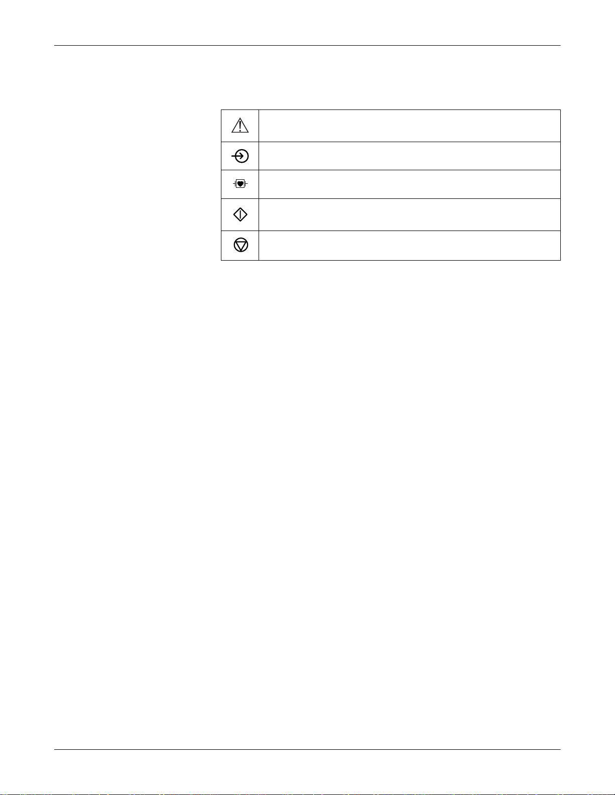
Symbols
Controls and Indicators: Symbols
Consult accompanying documents
Signal input
Type CF signal input, highly insulated, defibrillation-proof
Start
Stop
2-6 MAC 1200 Revision B
2012250-022
Page 33

3 Operating and
Performance Tests
Revision B MAC 1200 3-1
2012250-022
Page 34

For your notes
3-2 MAC 1200 Revision B
2012250-022
Page 35
Power Supply
Operating and Performance Tests: Power Supply
8
7
I
U
(
%
J
K
<
>
M
0
O9P
)
L
standby battery low
X
format/
speed
muscle
filter
gain
pat
info
copysetup
lead
store/
retrieve
12
6
arrhy
start
stop
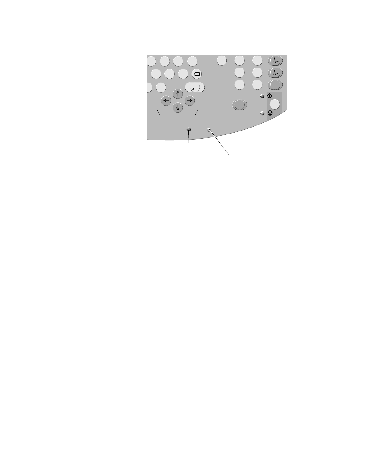
Indicator 2 Indicator 1
106A
Indicators
The units are powered from the power line or from the rechargeable
battery.
The battery charges automatically when the unit is connected to the
power line and the green indicator 2 is illuminated as shown above. It is
not necessary to switch on the device for charging. To ensure that the
battery is alway s fully charged, leave the e lectrocardiogra ph connected to
the power line whenever possible. The battery regains its full capacity
after being connected to the power line for four hours.
Indicator 1 is illuminated when the battery needs to be charged. The unit
can also be set up to emit an additional audio signal when the battery
requires charging.
With a full battery, about 50 ECGs (1 page each) can be recorded in the
12 Lead mode. When its capacity drops to about 25 recordings, the
battery is used up and must be replaced by a service specialist.
127(
To prolong the battery life, fully discharge the battery at least once
per month (by operating the electrocardiograph on battery power).
127(
In standby mode, a fully charged battery is drained within
approximately 4 hours. Therefore, when operating the device on
battery power, be sure to turn it off when it is not in use.
Revision B MAC 1200 3-3
2012250-022
Page 36
Operating and Performance Tests: Installation and Mains Connection
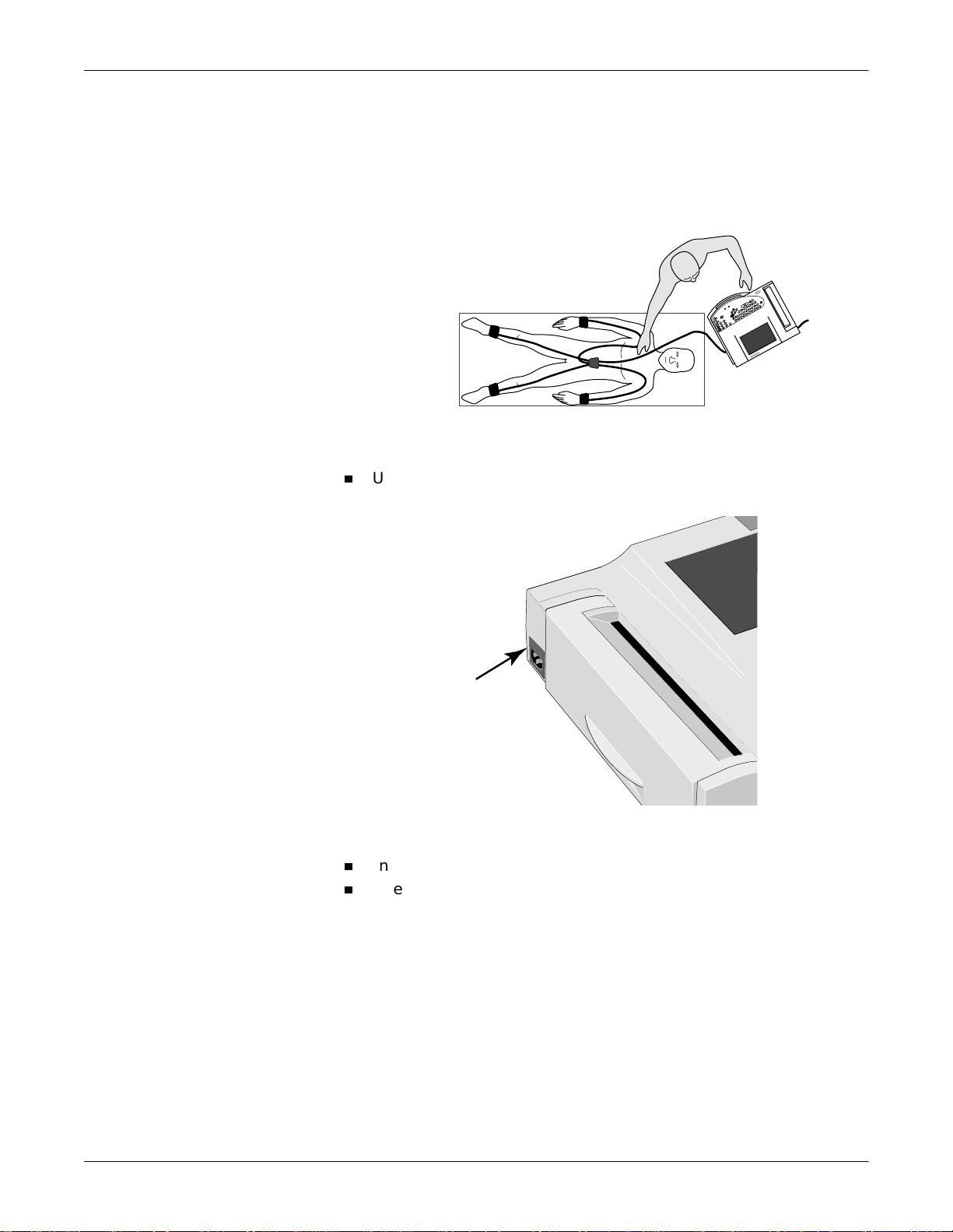
Installation and Mains Connection
The figure below shows a practical arrangement of patient and recorder.
For interfer ence-f ree oper atio n, it is import ant th at the patient cable a nd
the power cord do not run parallel.
Arranging the Electrocardiograph and the Examination Couch
Use the power cord to connect the device to the power line (see figure
below). Use only the original power cord or an equivalent cable.
003A
004A
AC Power Input
Indicator 2 will illuminate.
Check the paper supply (the window in the paper door allows you to
look inside the paper compartment). Refer to Chapter 10, “Loading
Chart Paper” for instructions on inserting a new paper pad.
3-4 MAC 1200 Revision B
2012250-022
Page 37

Operating and Performance Tests: Performance Check
Performance Check
Press the power bu tton to switch the device on.
The amber indicator will illuminate.
After power-up, the electrocardiograph runs an automatic self-test. The
display indicates the memories currently being tested. The self-test takes
about 15 to 20 seconds. When no problem is detected, the device defaults
to the 12 Lead mode. If a malfunction is identified, the dis p lay will show
an error message Error... In this situation, notif y ser vi ce to che ck an d
repair the device.
on
stdby
Q
1
!
A
Z;X
2
3
W
E
?
S
D
:
alt
Power Button
4
R
=
/
C
5
T
+
-
G
F
V,B.N
6
Y
*
H
005A
The self-test can be skipp ed with the button. In this case, the device
immediately activates the default mode confugured in the Setup menu.
127(
The backlighting of the display switches off automatically when no
key is activated for 20 minutes (adjustable). The illumination is
turned on again by activation of any key.
Run the full self-test at least once a day to ensure that the device is
functioning properly.
Press and hold the power button for several seconds to turn the
device off.
Revision B MAC 1200 3-5
2012250-022
Page 38

Operating and Performance Tests: Performance Check
Contrast Adjustment
Simultaneously press and the appropriate cursor key:
Alt
more contrast ,
less contrast .
3-6 MAC 1200 Revision B
2012250-022
Page 39

System Setup
Operating and Performance Tests: System Setup
The table below shows the system setup parameters that can be
modified, as well as the the fact ory defa ults . Refer to Chapter 9, “System
Setup” section for details.
Table 1. System Setup Menu
Parameter Factory Default Options
Ordering Physician none selection from a list of 10 names
Referring Physician none selection from a list of 10 names
Technician none selection from a list of 10 names
Institution Name empty text box text box for 40 characters
Cart # 1 1 ... 9999
1
Site #
Location # 1 ... 600
Ease of Clock Setting No Yes
Date (dd.mm.yyyy) current date
Time (hh:mm) current time
Lead fail beep No Yes
High HR beep No Yes
Lead Labels IEC AAMI
Pace Enhancement Yes No
Baseline roll filter 0.08 Hz 0.04 Hz, 0.16 Hz
Date dd.mm.yyyy mm/dd/yyyy
Time 24 12
Units cm, kg in, lb
Mains 50 Hz 60 Hz
LCD light off after 20 min 1 ... 99 min
Low battery beep 0 (Off) 5 s to 60 s (5 s = beep at 5 second
Default Mode 12-Lead 6-Lead, Arrhythmia (MAC 1200 only)
Language German all available languages
Enable password No Yes
Test DATA No Yes
Restore defaults No Yes
Print Configuration Lists No Yes
Print ECG Tx Log No Yes
Check Record Retxn No Yes
1 1 ... 255
interval)
Revision B MAC 1200 3-7
2012250-022
Page 40

Operating and Performance Tests: System Setup
1. only for CSI communication protocol
3-8 MAC 1200 Revision B
2012250-022
Page 41

Operating and Performance Tests: Connecting Peripheral Equipment
Connecting Peripheral Equipment
:$51,1*
SHOCK HAZARD — Strictly observe the following
warnings. Failure to do so may endanger the lives of the
patient, the user and bystanders.
Connecting peripheral devices to the RS2 32 interfa ce
of the electrocardiograph creates a medical system.
This system must meet the requirements of IEC
60601-1-1.
Use only the original GEMS IT connection cables.
All non-medical devices of a system must be
connected to the same electric circuit. Devices which
are not connected to the same circuit must be
electrically isolated (use isolated RS232 interface as
per IEC 60601-1).
A PC connected to the electrocardiograph should
meet the requirements of EN 60601. If it doesn't, it
must be set up outside the patient environment. If
the PC fulfills the requirements of EN 60950, it must
be set up within the medically used area, but outside
the patient environment.
Do NOT connect PCs to the electrocardiograph that
fulfill neither EN 60601 nor EN 60950.
Modems connected to the electrocardiograph must
meet the requirements of EN 60950 or UL1950 (all
modems recommended by GEMS IT meet these
requirements). The specific regulations valid in your
country must also be observed.
The modem must be set up within the medically used
area, but outside the patient environment.
Revision B MAC 1200 3-9
2012250-022
Page 42

Operating and Performance Tests: Connecting Peripheral Equipment
The electrocardiograph can be directly connected via the serial interface
to a PC (CardioSoft), to the CardioSys system, or to a MUSE CV system.
Resting ECGs acquired in the 12 Lead mode, and the corresponding data,
can then be transmitted to these peripheral devices. See Chapter 5,
“ECG Transmission” section for details.
The table below shows the factory defaults and all possible adjustments.
For instructions on changing the default setup, see “Communication” on
page 9-25 for details.
Table 2. Modem Configuration Menu
Parameter Factory Default Options
Choices for Modem —> Other
no other
MultiTech 19.2
MultiTech 56k
Elsa 14.4
Elsa 28.8
Elsa 33.6
Elsa 56k
Choices for Modem —> other
Phone Number
Initial. modem
AT&FM1X3S
0=1V0
dial string hangup
ATDT
+++ATH
Choices for Modem —> MultiTech, Elsa
Dial mode
Tone Pulse
Phone Number
Outside line
0 to 9 (20 digits)
0 to 9 (20 digits)
3-10 MAC 1200 Revision B
2012250-022
Page 43

For your notes
Operating and Performance Tests: Connecting Peripheral Equipment
Revision B MAC 1200 3-11
2012250-022
Page 44

Operating and Performance Tests: Connecting Peripheral Equipment
3-12 MAC 1200 Revision B
2012250-022
Page 45

4 Preparing for ECG
Recording
Revision B MAC 1200 4-1
2012250-022
Page 46

For your notes
4-2 MAC 1200 Revision B
2012250-022
Page 47

Preparing for ECG Recording: Connecting the Patient Cable
Connecting the Patient Cable
:$51,1*
SHOCK HAZARD — Strictly observe the following
warnings. Failure to do so may endanger the lives of the
patient, the user and bystanders.
For reasons of patient safety, use only the original
GE Medical Systems Information Technologies
patient cables. Before connecting the cable to the
device, check it for signs of mechanical damage. Do
not use a damaged cable.
Ensure that conductive parts (such as the patient,
connectors, electrodes, transducers) that are
connected to the isolated patient signal input do not
come into contact with other grounded, conductive
parts. This would bridge the patient's isolation and
cancel the protection provided by the isolated input.
The neutral electrode, in particular, must not come
into contact with ground.
If your electrocardiograph is equipped with an integrat ed suction pump
connector, you can connect the electrode application system KISS inst ead
of the standard patient cable.
Use the 10-lead patient cable for acquisition of the standard ECG leads
(Einthoven, Goldberger, Wilson).
Connect the patient cable to ECG signal input.
ECG Signal Input
!
006A
Revision B MAC 1200 4-3
2012250-022
Page 48

Preparing for ECG Recording: Electrode Application
Electrode Application
Careful application of electrodes and skin prepara tion are the key to an
interference-free ECG.
&$87,21
PATIENT HAZARD, Delayed ECG Display — Use only
silver-silver chloride electrodes when recording the ECG
of a patient who may have to be defibrillated. (Refer to
Chapter 8, “Pacemaker Patients / Recording During
Defibrillation” for details.)
4-4 MAC 1200 Revision B
2012250-022
Page 49
Preparing for ECG Recording: Electrode Application
R
A
Applying Plate (Limb) Electrodes
Plate electrodes are applied by means of a rubber strap, and electrode
paper is the recommended contact medium.
Moisten the electrode pap er with tap water a nd place it bet ween skin
and electrode.
Secure the electrode with the rubber strap, but do not hinder blood
circulation.
A
L
RL LL
Applying Limb-Lead Electrodes
Lead Description
RA (white) electrode on right arm
LA (black) electrode on left arm
LL (red) electrode on left leg
RL (green) electrode on right leg
&$87,21
Use only silver-silver chloride electrodes, if the patient
may have to be defibrillated. (See “ECG Recording
During Defibrillation” on page 8-4 for details.)
V
103A
Applying Suction Electrodes (Chest)
Shave application points, if necessary.
Moisten the electrode paper with tap water and place it between skin
and electrode. Electrode cream or gel can be used instead of paper. On
hairy chests, the cream or gel improves adhesion of the electrodes.
Revision B MAC 1200 4-5
2012250-022
Page 50
Preparing for ECG Recording: Electrode Application
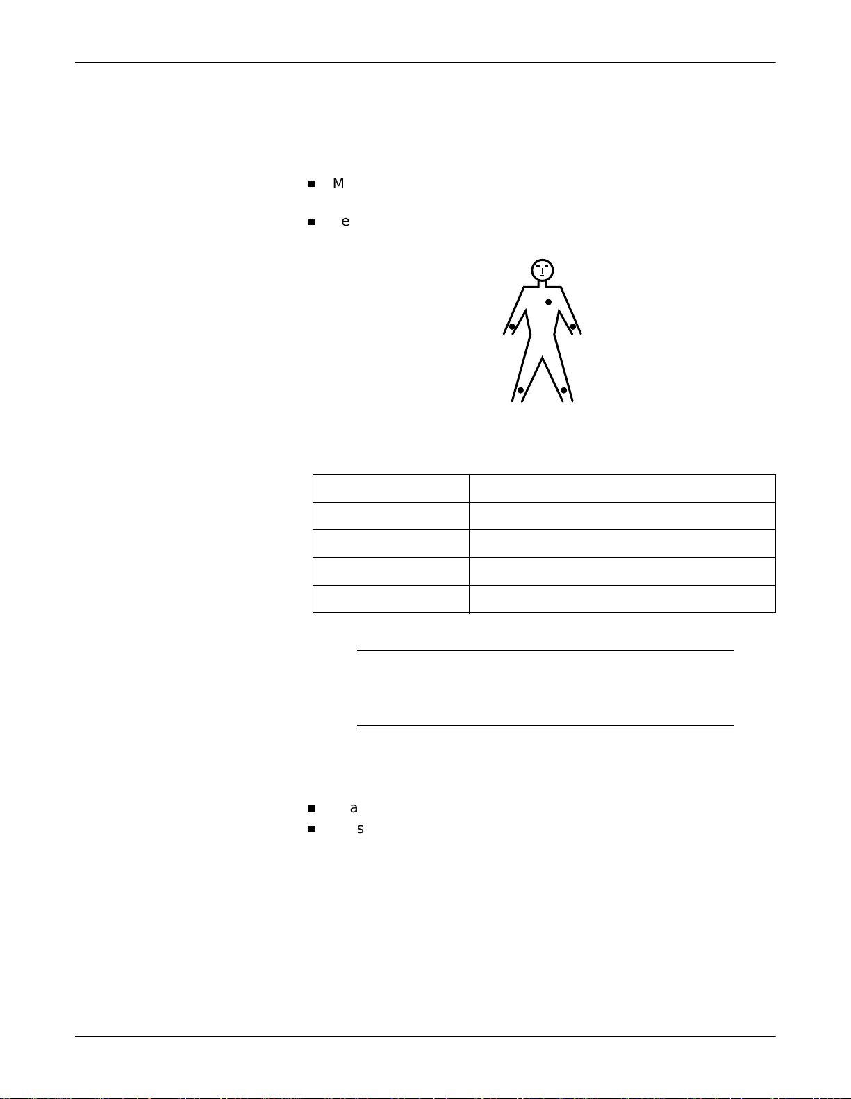
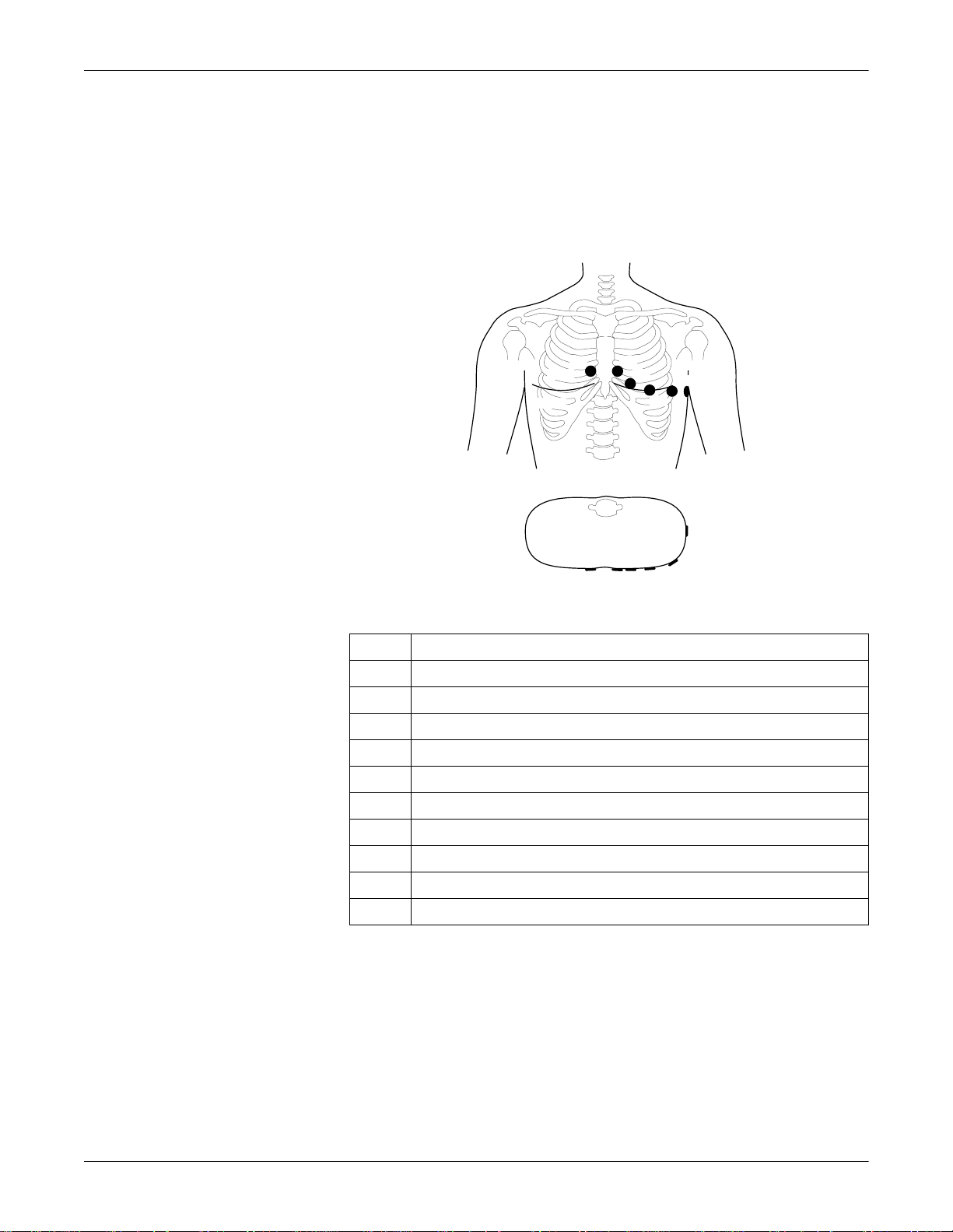
Electrode Placement for Standard Leads (l, II, III, aVR, aVL, aVF, V1...V6)
For acquisition of the standard ECG leads, four electrodes must be
applied on the limbs and six on the chest. The limb electrodes should be
placed above the wrists and ankles. The figure below shows the chest
electrode application points.
V1
V2
V2V3
V3
V4
V4
V5
V6
V6
V5
V1
Chest Electrode Placement
Description
V1 4th intercostal space at the right border of the sternum
V2 4th intercostal space at the left border of the sternum
V3 Midway between locations V2 and V4
V4 At the mid-clavicular line in the 5th intercostal space
V5 At the anterior auxiliary line on the same horizontal level as V4 and V6
V6 At the mid-auxiliary line on the same horizontal level as V4
7A
V7* At the left posterior auxiliary line in the 5th intercostal space
V8* At the left scapulary line in the 5th intercostal space
V3R* Opposite V3, on the right side of the chest
V4R* Opposite V4, on the right side of the chest
* additional standard leads
4-6 MAC 1200 Revision B
2012250-022
Page 51

Preparing for ECG Recording: Electrode Application
Connect the 10-lead patient cable as shown below.
RL green
RA white
right leg
right arm
V1 red
V2 yellow
V3 green
V1
V2
V3
V4
V5
V6
V4 blue
V5 orange
V6 purple
LA black
LL red
left arm
left leg
V1
V2V3
V4
V6
V5
Connecting the Patient Cable (10-Lead Cable, Standard ECG Leads)
Arrange the leadwires and patient cable as shown below.
009A
Correct
Incorrect
010A
Arranging the Patient Cable
Revision B MAC 1200 4-7
2012250-022
Page 52
Preparing for ECG Recording: Electrode Application
A
Artifact Due to Poor Electrode Application
The electrocardiograph is equipped with state-of- the-art electronic
utilities that ensure artifact-free recordings. Among these are the
automatic baseline adjustment and the anti-drift system (cubic spline)
(ADS).
At the beginning of the recording the automatic baseline adjustment
algorithm verifies the incoming signal and adjusts the baseline position
accordingly.
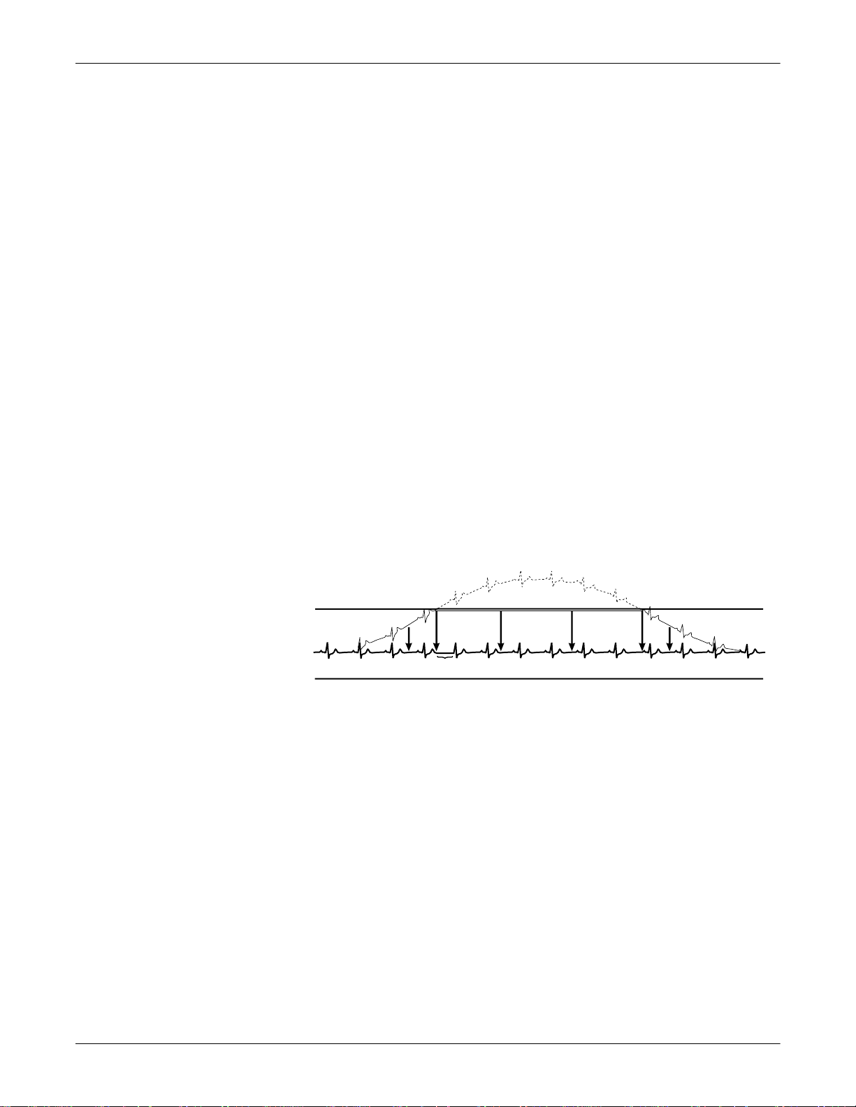
During the recording, the anti-drift system (cubic spline) continuously
checks the baseline position and returns it to the normal level, if
required (see Sample Recording figure).
For the Manual Mode, the anti-drift system (cubic spline) can be enabled
and disabled from the setup menu, in the 12 Lead and Arrhythmia
Modes, it is always enabled.
When electrodes are not properly applied, these measures may not fully
compensate for artifact. High polarization voltages induced by electrodes
applied without conductive gel may cause the amplifier to overrange, so
that a straight line will be recorded instead of the ECG (see figure). In
this situation the device will automatically block and return the baseline
to its normal position. A baseline is then recorded for approximately 1
second. It is possible to block the amplifiers manually by disconnecting
the R electrode.
approximately 1 second
013
Sample Recording
On the display th is condit io n i s i ndi cated b y **** i ns te ad of t he el ectrode
label).
4-8 MAC 1200 Revision B
2012250-022
Page 53

Remedy
Preparing for ECG Recording: Electrode Application
Apply the electrodes according to instructions.
Do not apply the electrodes on top of clothing.
Use a contact agent (e.g. mois tened el ectrod e paper, ele ctrode cream ,
spray, etc.).
Wait approximately 10 seconds before initiating a recording. After
the 10-second period, the automatic functions are enabled and the
polarization volta ges have stabilized, provided the electrodes are
properly applied. In case of improper electrode application, an error
message will appear on the display (RL, LL, LA, LL, V1 to V6).
If required, the ADS (cubic spline) and the filters (20/40 Hz, 50 Hz)
can be disabled to verify the “raw” ECG signal.
Revision B MAC 1200 4-9
2012250-022
Page 54

Preparing for ECG Recording: Entering Patient Data
pat
info
Entering Patient Data
It is possible to enter patient data and have them annotat ed on the
recording for easy archiving of patient records.
Press to enter the patient data mode.
The recorder displays the menu items in a defined order. In the
configuration menu (see “Pat ient Data Menu Setup” on page 9-27
for details) you determine the items to be included in the menu
(In the table on the next page, the items that appear in the
patient data menu in the default configurat ion are marked as Yes
in the Menu item displayed column, the other menu items are
marked as No.
To skip a menu item, press or the cursor key or .
It is not possible to write capital and small letters (do not press
the Shift key). For entry of numbers (e.g. date of birth), it is not
necessary to press the Shift key.
For fields that allow alphanumeric e ntries the NumLock function
can be enabled with (the symbol appears in the upper
format/
speed
right corner of the display).
All entries must be confirmed with .
Press or to exit the patient data mode.
info
pat
127(
Please refer to the Appendix for instructions on entering special
characters.
4-10 MAC 1200 Revision B
2012250-022
Page 55

Preparing for ECG Recording: Entering Patient Data
The table below shows the menu items in the correct order. On the
display, selected options are shown in brackets. After the table each
Parameter is explained in detail.
Table 1. Patient Data Entry Menu
Parameter
Adjusted Menu Item Displayed
Factory Default
Options
New Patient No Yes Yes
Last name Yes
First name Yes
Date of Birth 00.00.0000(dd.mm.yyyy) Yes
Patient ID Yes
Chest pain
1
Unknown Yes Secondary Complaint, Chief Complaint
Pacemaker No Yes Yes
Gender - Yes female, male
Height Yes
Weight Yes
Race unknown Yes other
Systolic BP 0 mmHg Yes
Diastolic BP 0 mmHg Yes
Ordering Physician Yes selection from a list of 10 names
Referring Physician Yes selection from a list of 10 names
Technician Yes selection from a list of 10 names
Phone No. -- Yes
Medication Yes
1. unknown Yes other
2. unknown Yes other
Comments Yes
ID Required Yes
Patient ID Length Yes 3 to 16 characters; default is 9 characters
Secondary ID No
Secondary ID Required No
Last Name Required No
First Name Required No
Location # No 1 ... 600
Room No
Order number No
Prompt 1 No
Revision B MAC 1200 4-11
2012250-022
Page 56

Preparing for ECG Recording: Entering Patient Data
Parameter
Prompt 2 No
Prompt 3 No
Prompt 4 No
1. with 12SL program only. This will appear only if the ACI-TIPI option is enabled in the HARDWARETESTS menu.
Refer to the MAC 1200/1200 ST Service Manual for more information on enabling this option.
New Patient
Last Name, First Name
Table 1. Patient Data Entry Menu
Factory Default
Adjusted Menu Item Displayed
Yes: existing patient data are deleted.
No: entered data can be edited.
Last name: 16 characters.
First name: 10 characters.
Options
Date of Birth
Patient ID
You do not need to enter separators between date, month, and year
fields.
format/
The button has the function of the Shift-Lock key when entering
speed
data in alphanumeric text boxes. This function allows you to enter the
characters shown in the upper part of the keys, without pressing the
Shift key. The symbol appears in the display to indicate the ShiftLock status.
This field accepts 3 to 16 characters. The exact length is determined in
the patient data setup menu.
127(
When entering a patient ID whi ch consists of numerals only, the
blanks preceding the number are replaced with 0. Example: If a 6digit text box is configured and you enter the patient ID 123, the final
ID number will read “000123”.
4-12 MAC 1200 Revision B
2012250-022
Page 57

Chest Pain
Pacemaker
Preparing for ECG Recording: Entering Patient Data
127(
The chest pain option is for use with 12SL program only. This will
appear only if the ACI-TIPI option is enabled in the
HARDWARETESTS menu.
The entry for this menu item is pass ed on to th e 12SL AC I-TIPI program
which considers it in the test interpretation. If you choose one of the
options and, additionally, enter the patient’s gender and date of birth,
and whether the chief complaint is of chest pain, the program will
determine a percentage value indicating the probability of acute
ischemia. This value alon g with a reason for this conclusion will appear
in the interpretation.
Influences the identification of pacer pulses in Arrhythmia Mode. Enable
the function Yes when recording the ECG of a pace maker patient. The
recording will then be annotated with the messa g e Pacemaker Patient.
Gender/Race
These parameters influence the ECG. If you do not intend to enter all
patient data, select the neutral entries “-” and unknown.
Height/Weight
Enter the patient's height (cm) and weight (k g). The weight can be
entered with one decimal place.
Systolic BP/Diastolic BP
Enter the blood pressure readings in mmHg.
Revision B MAC 1200 4-13
2012250-022
Page 58

Preparing for ECG Recording: Entering Patient Data
Ordering Physician / Referring Physician / Technician
When you choose Yes for New patient, the de fault names entered in the
System Setup will appear here. When you choose other, you can pick a
name from the list. It is also possible to choose none. You can press
to quit the list. The Referring Physician is only relevant if you
send ECGs to the MUSE CV system. This name will not be annotated on
the ECG recording.
Phone Number
Enter the patient’s telephone number.
Medication
Enter the patient’s medications and confirm entries with .
Comments
ID Required
Secondary ID
4 lines of 30 characters each
Default value is Yes.
This field accepts 3 to 16 characters. The exact length is determined in
the patient data setup menu.
If Secondary ID Required is enabled, then Secondary ID must also be
enabled.
4-14 MAC 1200 Revision B
2012250-022
Page 59

Preparing for ECG Recording: Entering Patient Data
Secondary ID Required
Yes: patient secondary ID required.
No: patient secondary ID not required.
If Secondary ID is enabled, then Secondary ID Required must also be
enabled.
Last/First Name Required
Yes: patient last or first name required.
No: patient last or first name not required.
Location Number
ID number for the location (3-place). When you select Yes for New
patient, the default value from the System Setup will auto matically be
adopted, but you can overwri te this number.
Room
Order Number
Prompts
5 digits
9 digits for entry of the ECG order number.
Answer the prompts entered in the patient data setup menu. (See
“Patient Data Menu Setup” on page 9-27 for details).
Revision B MAC 1200 4-15
2012250-022
Page 60

For your notes
Preparing for ECG Recording: Entering Patient Data
4-16 MAC 1200 Revision B
2012250-022
Page 61

5 Recording in 12 Lead
Mode
Revision B MAC 1200 5-1
2012250-022
Page 62

For your notes
5-2 MAC 1200 Revision B
2012250-022
Page 63

Recording in 12 Lead Mode: General Information
General Information
In 12 Lead mode, 12 leads of ECG are acquired simultaneously for a
period of 10 seconds. When initiated with , the recording
proceeds automatically.
Depending on the implemented software options, the ECG is:
Units equipped with the optional memory function MEMO (MAC 1200
only) can save up to 40 resting ECG. These ECGs can be printed or sent
to CardioSys/CardioSoft (A5 protocol) or to the MUSE CV system (CSI
protocol) (see “The Storage Program” on page 5-8).
The unit offers different report formats for printout of t he ECG. With the
system defaults, all 12 leads including the measurement and analysis
results will be documented on a single sheet. (See “Report Formats” on
page 5-10.)
only printed out (MAC 1200 without options MEAS, DIAG),
measured and printed out with the measurement results (MAC 1200
with option MEAS), and
measured, interpreted (analyzed) and printed out with the
interpretative statements (MAC 1200/1200 ST with option DIAG).
Some of the system settings can be customized. They are identified with
“configurable.”
Revision B MAC 1200 5-3
2012250-022
Page 64

Recording in 12 Lead Mode: General Information
The following information refers to a unit with the system defaults. For
instructions on changing the default setup, see “12 Lead Mode” on
page 9-5.
Table 1. Setup Menu for the 12 Lead Mode
Parameter Factory Default Options
Report Sequence STANDARD CABRERA
Rhythm Leads II, V1, V5 I, III, aVR, aVL, aVF, V2, V3, V4,
V6
Gain 10 mm/mV “*auto”, 5, 20, 40 mm/mV
Report Format 4x2.5R1 1x10R12, 2x5R1, 2x5_50,
4x2.5R1, 1x10R3, 4x2.5R3
Detailed Results No Yes
Muscle Filter No Yes
Muscle Filter Frequency 40 Hz 20 Hz
AC Filter Yes No
Manual copy to EKG HOST
Number of copies 1 0 to 9
Delete ECG after
No Yes
Transmission
Autosave ECG No Yes
Use Screening criteria No Yes
Suppress NORMAL
No Yes
statement
Suppress ABNORMAL
No Yes
statement
Interpretation Yes No
Print Interpretation No Yes
Override function No Yes
5-4 MAC 1200 Revision B
2012250-022
Page 65

Recording
Recording in 12 Lead Mode: Recording
127(
When an electrode is off the patient or it has failed in some other
manner, the unit will record an ECG unless the override function has
been enabled in the 12 Lead Setup menu.For more information, see
Chapter 9, “12 Lead Mode” .
When the unit is powered up, it defaults to the 12 Lead mode (this
default setting can be modified).
1. Before recording the ECG, patient data can be entered ( ). It is
info
pat
recommended that you enter the patient's name so it appears on
every report.
2. After applying the electrodes, wait about 10 seconds for the signal to
stabilize (stabilization of polarization voltages, see Chapter 4,
“Artifact Due to Poor Electrode Application” ). If you initiate a
recording with immediately after selecting the 12 Lead
mode, the message Collecting data displays, and you will need to
wait for 10 to 12 seconds.
Before initiating a recording, check the display for error messages.
Check all electrodes; if the message persists, there must be a break
in the patient cable. Replace the cable with a new one.
Table 1. Messages Indicating Disconnected Electrodes
Symbol Description
*RL*: Right leg electrode disconnected
*RA*: Right arm electrode disconnected
*LA*: Left arm electrode disconnected
*LL*: Left leg electrode disconnected
*V1*: Chest electrode V1 disconnected
*V2*: Chest electrode V2 disconnected
*V3*: Chest electrode V3 disconnected
*V4*: Chest electrode V4 disconnected
*V5*: Chest electrode V5 disconnected
*V6*: Chest electrode V6 disconnected
Revision B MAC 1200 5-5
2012250-022
Page 66
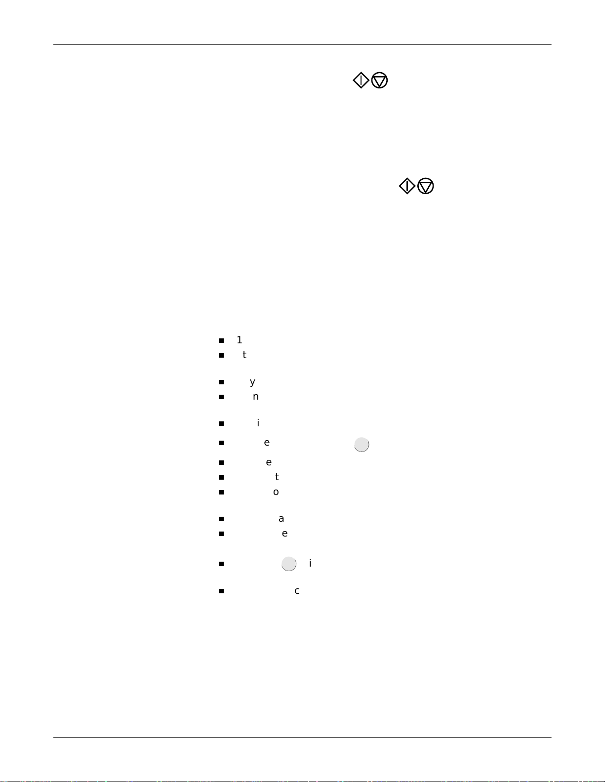
Recording in 12 Lead Mode: Recording
3. Initiate a recording with . The MAC 1200 acquires all 12
leads simultaneously for 10 seconds, and then generates a printout.
127(
The device can be set up to allow a recording only when specific
patient information has been entered (last name, first name, ID,
Secondary ID, for more information, see “Patient Data Menu
Setup” on page 9-27).
When you initiate a recording with , the unit prints the most
recent 10 seconds of ECG data and analyzes it. Therefore, wait un til
the patient has been lying relaxed and motionless for about 10
seconds before starting the recording.
127(
Filters may suppress diagnostically relevant portions of the
signal, because th ey limit the transmission range. Therefore,
only enable filters if necessary.
With the system defaults unchanged, the unit will activate the following
functions and settings after power-up (system defaults which can be
changed are indicated with “configurable”).
12 Lead mode (configurable)
Standard report sequence (lead to channel correspondence): I, II, III,
aVR, aVL, aVF, V1, V2, V3, V4, V5, V6
Rhythm leads II, V1 and V5 (configurable)
Gain of 10 mm/mV (configurable) (calibration pulse at the beginning
of the recording)
AC filter is on (configurable)
Muscle filter is disabled ( ) (configurable)
AC line filter is enabled (configurable)
ADS (anti-drift system) is always enabled
Report format is 4x2.5R1, i.e. 12 leads and al l data are printed o n one
muscle
filter
page (configurable)
Interpretation is printed (configurable)
Detailed results page (including the median complexes and the
measurement results) is not printed (configurable) (MAC 1200 only)
Pressing will produce one copy of the printed ECG
copy
(configurable)
Override function is disabled (configurable)
5-6 MAC 1200 Revision B
2012250-022
Page 67
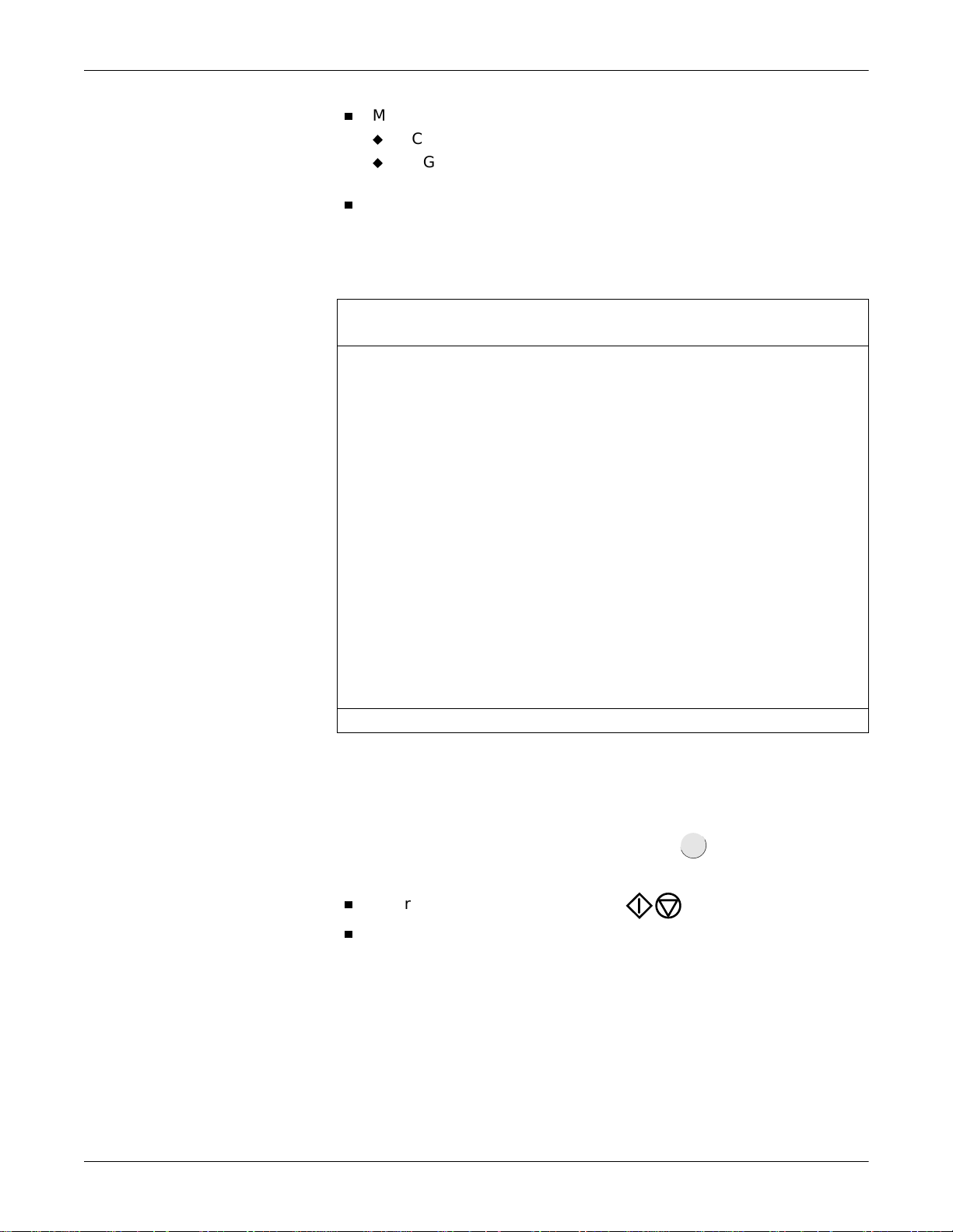
Recording in 12 Lead Mode: Recording
MAC 1200 with the MEMO (memo ry) option
ECGs are not automatically stored (configurable)
ECGs that were successfully transmitted to a host system are not
automatically removed from memory (configurable)
QTC is calculated with the Bazett formula (only MAC 1200 with option
MEAS (measureme nt) or DIA G ( mea sur em ent + i n terp re tati on) ).
The locations of all relevant device settings are shown below:
Operating mode Muscle filter
Report function
2
Failure message
1
AC line filter1Anti-drift system1“Patient Name”
Gain Report sequence
Three leads
display here
3
1. if enabled
2. or REC OFF when the recording function is disabled
3. if any
Heart rate
The display shows three leads at a time. With you can display all
lead
leads of the report sequence in groups of three.
The recording can be stopped with .
For a description of the different reports, see “Report Formats” on
page 5-10.
Revision B MAC 1200 5-7
2012250-022
Page 68
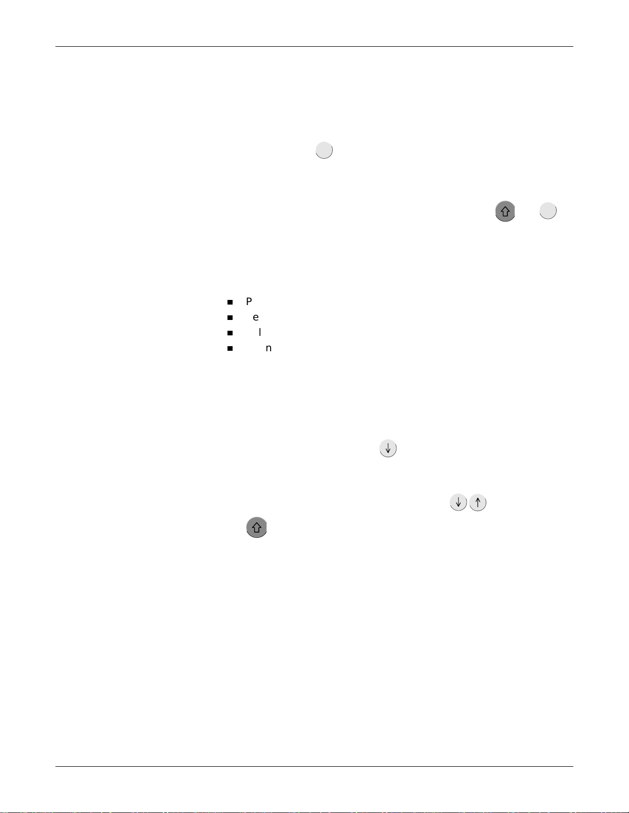
Recording in 12 Lead Mode: The Storage Program
The Storage Program
With MAC 1200 units equipped with the optional storage program
MEMO the ECG including patient, measurement and analysis data can
be saved with the button after ECG acquisition. A message informs
the user that ECGs are being saved and indicates the number of stored
ECGs.
store/
retrieve
To retrieve an ECG from memory, simultaneously press and .
store/
retrieve
127(
With a fully charged battery and the unit turned off, ECGs will
remain stored for approximately 4 weeks.
The function keys appear at the top of the menu:
Print (prints the selected ECG)
Send (see “ECG Transmission” on page 5-12)
Delete (deletes the selected ECG)
Change (enables modification of the patient data)
When you view a saved ECG, the Print function is selected. The list on
the next page shows all patients for whom ECG are stored.
To perform an action with one or more ECGs, you must first select the
ECG(s). Follow these steps:
1. Move the cursor down with . When the cursor reaches the Print
directory, it moves on to the patient list. In the list, the bar cursor
changes to a line cursor.
2. To select multiple ECGs, select them with , while holding
down. Selected ECGs are marked with a black bar in the margin
of the display. Deselect the ECGs with the same key combination.
5-8 MAC 1200 Revision B
2012250-022
Page 69

Recording in 12 Lead Mode: The Storage Program
127(
Due to the limited size of the display, you cannot view the entire
list at a time. These are the columns that follow to the right of
the patient name:
Date and time of the ECG recording
S (indicates that the ECG has been sent to another system)
Patient ID
Comments
To display the remaining columns, you can continuously scroll
the display with or you can shift the list by the display’s
width with and .
Alt
3. When you have selected all ECGs to view, press the key to
return to the function keys.
4. Use the cursor to select the function you need. Initiate it with .
Other Considerations
With the Print directory command, you can print a list of all stored
ECGs. The printout includes all columns, except the Comments column.
If you try to save an ECG when the memory is full, a message informs
you of the memory status. When you delete an ECG from memory, the
new ECG will automatically be saved.
The unit may be set up to automatically save ECGs (without pressing
/
) and automatically remove ECGs from memory that were
C
successfully transmitted to the CardioSys, CardioSoft or MUSE systems.
The storage program can be terminated at any time with .
127(
If you plan to print a large number of stored ECGs, connect the unit
to the power line or to check that the battery is fully charged.
When you terminate the storage program with , it is not
possible to save the current ECG again.
Revision B MAC 1200 5-9
2012250-022
Page 70

Report Formats
Recording in 12 Lead Mode: Report Formats
The length and scope of the reports depends on the implemented
software (standard, MEAS ( measurement), DIAG (measurement +
interpretation)).
The table below shows all of the 14 different report formats available
with MAC 1200 units.
Format
4x2.5R1
(default format)
4x2.5R3 4x2.5 s/4x3 10 s/3 25 mm/s Yes Yes 1 4x2.5R3
2x5R1 2x5 s/2x6 10 s/1 25 mm/s Yes Yes 1 2x5R1
2x5_50 2x5 s/2x6 No 50 mm/s Yes Yes 2 2x5_50
1x10R12 10 s/1x12 No 25 mm/s No No 1 1x10R12
1x10R3 10 s/1x3 10 s/3 25 mm/s Yes Yes 1 1x10R3
4x2.5R1
(default format)
4x2.5R3 4x2.5 s/4x3 10 s/3 25 mm/s Yes Yes 1 4x2.5R3
2x5R1 2x5 s/2x6 10 s/1 25 mm/s Yes Yes 1 2x5R1
2x5_50 2x5 s/2x6 No 50 mm/s Yes Yes 2 2x5_50
1x10R12 10 s/1x12 No 25 mm/s No No 1 1x10R12
1x10R3 10 s/1x3 10 s/3 25 mm/s Yes Yes 1 1x10R3
4x2.5R1
(default format)
MUSE1 4x2.5 s/ 4x3 3x10 s / 2 25 mm/s yes yes 1 no
MUSE2
ECG Traces
Length/Leads
4x2.5s/4x3 10 s/1 25 mm/s Yes Yes 1 4x2.5R1
4x2.5s/4x3 10 s/1 25 mm/s Yes Yes 1 4x2.5R1
4x2.5s/4x3 10 s/1 25 mm/s Yes Yes 1 4x2.5R1
2
4x2.5 s/ 4x3 3x10 s / 2 25 mm/s yes yes 1 no
Rhythm Lead
Length/Leads
Speed
Measurement
1
Interpretation* Pages Medians
(default format)
(default format)
(default format)
1. Measurement results and interpretative statements are only available from MAC 1200 with the appropriate software
options
2. MUSE2 report format is only available on Pharma devices.
127(
Heart rate is calculated from all beats of the 10-second ECG.
Printed reports are unconfirmed documents. They must be overread,
verified, and signed by a physic ian for confirmation.
5-10 MAC 1200 Revision B
2012250-022
Page 71

Detailed Results
Recording in 12 Lead Mode: Report Formats
The MAC 1200 (with option MEAS or DIAG) setup menu allows you to
choose the Detailed Results page. When selected, this page will be
appended to the report. It contains patient data, measurement results,
interpretative statements (rea sons are only annotated if the unit is
equipped with the HEART interpretation program), medians and the
tabular measurement values.
127(
To obtain a printout of the full patient data, select the 6 Lead
mode and press .
copy
Revision B MAC 1200 5-11
2012250-022
Page 72
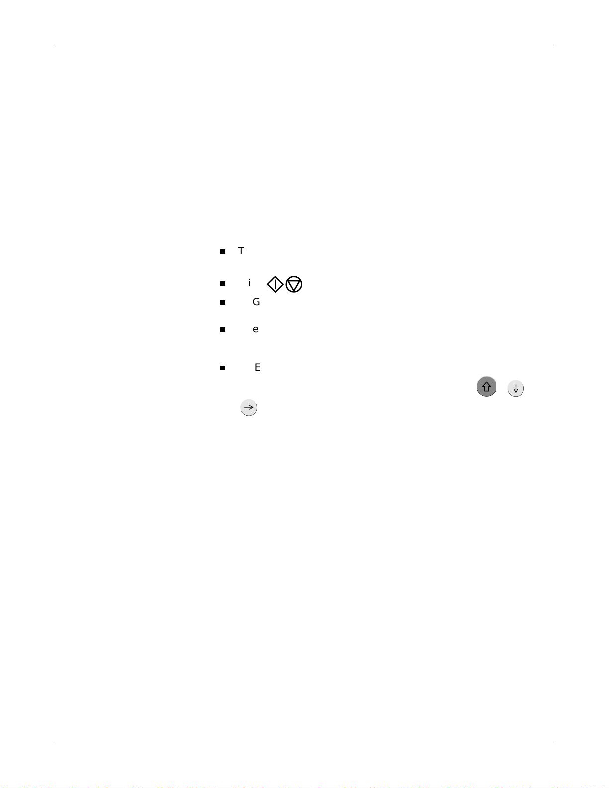
Recording in 12 Lead Mode: ECG Transmission
ECG Transmission
127(
Resting ECGs acquired in 12 Lead mode can be transmitted to
CardioSys/CardioSoft or to a MUSE CV system. The units can either
communicate via modem or directly via a connection cable (see “Direct
Transmission” on page 5-16).
General Considerations
Observe the safety information given in Chapter 3, “Connecting
Peripheral Equipment” .
The status of transmission progress is indicated on the display with
message text, e.g., “Transmitting 1 of 1,” or “Transmitting 2 of 6.”
With the transmission can be stopped.
ECGs that were successfully transmitted are identified with the
letter S (for “Sent”).
After the selected ECG records have been successf ully transmitted, a
confirmation message displays, e.g. “6 of 6 ECG records successfully
transmitted.”
All ECG records are time stamped (hours, minutes, and seconds). To
Transmission via Modem
Depending on the modem mo del u sed, th e m od em MUST be co nnect ed
either with the 9-pole cable 223 378 01 or with the 25-pole cable 223 378
02.
For transmission of the ECG, the unit must be set up as described in
“ECG Transmission via Modem” on page 9-3 0.
view a record’s time stamp, highlight it. Then press + . Use
to scroll right to see the time stamp.
5-12 MAC 1200 Revision B
2012250-022
Page 73

Recording in 12 Lead Mode: ECG Transmission
1. After acquiring the ECG, start the transmission with .
copy
127(
Manual copy to: HOST must be enabled in the 12 Lead setup
menu.
The MAC 1200 is also capable of transmitting stored ECGs (if
memory option MEMO is installed).
Activate the storage program by simultaneously pressing and
store/
. (Press the button first and hold it depressed.)
retrieve
2. To select one or more ECGs for transfer, move the cursor down with
.
When the cursor reaches Print directory, it moves on to the patient
list. In the list, the bar cursor changes to a line cursor.
To select multiple ECGs, select them with , while holding
down. Selected ECGs are marked with a black bar in the margin
of the display. Deselect ECGs with the same key combination.
3. When you have selected the ECG(s) to transfer, press . You will
be returned to the function key menu.
4. Using the cursor, select the Send command. Confirm your choice
with .
The transmission menu will be displayed, showing the phone number
and the options Start transmission, Modify settings, and Cancel.
5. Check the displayed telephone number and press to initiate the
transfer.
If it is necessary to change the number, press to display the
setup
configuration menu.
6. As soon as you initiate the transmission with , the unit
automatically dials the number of the modem at the receiving end
and establishes a connection.
Revision B MAC 1200 5-13
2012250-022
Page 74

Recording in 12 Lead Mode: ECG Transmission
The message Initializing transmission is displayed, and the option to
cancel the transmission is provided. Then it will send the ECG.
7. After the transmission, a message on the display indicates the
number of successfully transmitted ECGs. As soon as you
acknowledge the message with , the 12 Lead mode acquisition
screen appears.
8. If the ECG could not be transmitted (wrong modem setup, modem
off, etc.), the unit will display an error message, such as
Transmission Error! (A5).
In this situation you have the following choices:
Repeat the transmission with .
Error Messages
Change the settings with .
Stop the transmission with .
setup
You must select one of these choices to clear the transmission error
message from the display.
127(
Unsuccessful transmission does not remove/delete the ECG
record from the local database.
Transmission error messages are listed below.
ECG transmission error! (A5)/(CSI) (depending on selected protocol)
Check interface!
Dial locked! (temporarily)
No dial tone!
Busy!
No answer!
No carrier!
Check modem configuration!
5-14 MAC 1200 Revision B
2012250-022
Page 75

Batch Transmission
Recording in 12 Lead Mode: ECG Transmission
The MAC 1200 unit can send all untransmitted records in a batch
transmission.
1. Activate the storage program by simultaneously pressing and
store/
. (Press the button first and hold it depressed.)
retrieve
2. Select Send All Unsent Records. Confirm your choice with .
The message Initializing transmission is displayed, and the option to
cancel the transmissi on is provided.
Then it sends batch of ECG records.
3. After the transmission, a message on the display indicates the
number of successfully transmitted ECGs. As soon as you
acknowledge the message with , the 12 Lead mode acquisition
screen appears.
Transmission Log
The MAC 1200 unit can be set up to automatically print a log of the
recently completed transmission. See “Transmission Log” on page 9-24
for more information.
If the Transmission log is enabled, after tran smission is complete, the
message Print transmission log? will display.
Press to print the log.
The message Printing Transmission Log displays as the log is printing.
Revision B MAC 1200 5-15
2012250-022
Page 76

Recording in 12 Lead Mode: ECG Transmission
Transmitting Data to a MUSE CV System Via Modem
127(
Pacemaker information, telephone number and comments entered in
the patient data are not transmitted to the MUSE CV system.
Before sending data to the MUSE CV system, the MAC 1200
automaticall y logs on to th e datab ase. Th en the d ata tra nsfer is ini tiated.
If the transfer is stopped, the MAC 1200 takes a few seconds before
cancelling the connection because it has to log off the database first.
Then the communication link with the receiving modem is interrupted
and the standard display reappears.
ECG Record Serial Number
Every ECG record sent to the MUSE CV system contains a unique serial
number for tracking purposes. It is made up of the MAC 1200 serial
number + date + time.
127(
The ECG record serial number is printed on the transmission log
only (if enabled). It d oes no t a pp ear on th e ECG report p rint ed a t the
MAC 1200 unit. See “Transmission Log” on page 9-24 for more
information.
Direct Transmission
The unit must be connected to the PC or to the MUSE CV system by
means of the connection cable (pn 223 362 03).
For transmission of the ECG, the unit must be set up as described in
“Direct ECG Transmission” on page 9-31.
1. After acquisition of the ECG, the transmission is started with .
copy
127(
Manual copy to: HOST must be enabled in the 12 Lead setup
menu.
The MAC 1200/1200 ST is also capable of transmitting stored ECGs
(if the memory option MEMO is installed).
Activate the storage program by simultaneously pressing and
store/
. (Press the button first and hold it depressed.)
retrieve
5-16 MAC 1200 Revision B
2012250-022
Page 77

Recording in 12 Lead Mode: ECG Transmission
2. To select one or more ECGs for transfer, move the cursor down with
. When the cursor reaches Print directory, it moves on to the
patient list. In the list, the bar cursor changes to a line cursor.
To select multiple ECGs, select them with , while holding
down . Selected ECGs are marked with a black bar in the margin
of the display. Deselect the ECGs with the same key combination.
3. When you have selected the ECG(s) to transfer, press and you
are back in the function key menu.
4. Using the cursor, select the Send command. Confirm your choice
with .
The message Initializing transmission is displayed, and the option to
cancel the transmissi on is provided.
Then it starts. The message ECG Transmission (A5) is displayed.
5. After the transmission, a message on the display indicates the
number of successfully transmitted ECGs. As soon as you
acknowledge the message with , the 12 Lead mode acquisition
screen appears.
Revision B MAC 1200 5-17
2012250-022
Page 78

Recording in 12 Lead Mode: ECG Transmission
6. If the ECG could not be transmitted (e.g. wrong baud rate,
connection error), the unit will display the error message
Transmission Error! (A5)/(CSI).
The message depends on the s elected protocol.
127(
Pacemaker information, telephone number and comments
entered in the patient data are not transmitted to the MUSE CV
system.
In this situation you have the following choices:
Repeat the transmission with .
Change the settings with .
Stop the transmission with .
You must select one of these choices to clear the transmission error
message from the display.
127(
Unsuccessful transmission does not remove/delete the ECG
record from the local database.
5-18 MAC 1200 Revision B
2012250-022
Page 79

Receiving Data
Recording in 12 Lead Mode: ECG Transmission
See Chapter 13, “Technical Specifications” for additio nal informat io n.
Receiving ECGs is only possible with MAC 1200 units. The units must be
in the 12 Lead mode.
1. Use the key combination and to display the screen for
copy
receiving ECGs. The connected modem is automatically initialized.
The procedure can be aborted wi th .
2. Press to enable the receive data mode.
3. When you have enabled the receive data mode, the standard screen
display of the 12 Lead mode displays. The message 12 Lead (REC)
indicates that the unit is ready to receive data.
4. A message displays on th e screen when the unit is receiving data.
The reception of data can be aborted with .
5. The ECG which has just been received is processed for the printout.
The report is printed in the selected format. Multiple ECGs are
received and printed one after the other.
After printout of the last ECG, the receive data mode is automatically
disabled. The mode is also disabled when you select another
operating mode .
The following information is annotated in the bottom line of each
report.
Sender
Software version and analysis program version used at the
sending unit (e.g. ACQ-DEV: V5.1M12i HEART V5.1)
127(
Received records are printed by the MAC 1200, but are not stored
by the MAC 1200.
Revision B MAC 1200 5-19
2012250-022
Page 80

Recording in 12 Lead Mode: ECG Transmission
Cart to Cart Communication
Via modem, ECG data can be transmitted between two MAC 1200 units
or between a MAC 1200 and any ECG recorder using the CSI protocol
(see “Transmission via Modem” on page 5-12 and “Transmitting Data to
a MUSE CV System Via Modem” on page 5-16).
Modem Setup (for Modem → Other)
If you prefer to use another modem than the standard models listed in
the Setup menu (MultiTech, Elsa), you will have to enter a few
parameters required for communication between the MAC 1200 and the
modem.
For the AT commands which your modem understands, please refer to
the modem user instructions. Three command sequences have to be
entered, each of which d efines a specific modem operating state.
1. The modem is initialized (init string).
2. A communication link is established (dial string).
3. The communication is terminated (hangup string).
These three strin gs are entered in the modem setup menu. (See Chapter
3, “Connecting Peripheral Equipment” )
The example below shows the command strings for the MultiTech ZDX
modem.
AT Command for Modem Initialization
Symbol Description
AT Prefix that precedes every command line
&F Fetch factory configuration (loads the factory configuration from ROM into the
active configuration memory (RAM))
M1 Speaker is always on
X3 Call progress signal monitoring enabled
S0=1 Auto answer after one ring
V0 Digit result codes selected (0 to 999)
init string: AT&FM1X3S0=1V0
5-20 MAC 1200 Revision B
2012250-022
Page 81

Recording in 12 Lead Mode: ECG Transmission
AT Command for Establishing a Communication Link
The following is an example of a dial string for a modem connected to a
branch (PBX system) and dialing a modem via the public telephone
network, using the touch tone mode.
Symbol Description
AT Pr efix that prec edes every command line
DT Touch tone dial mode
xxx After DT, enter the characters for access to the public telephone network
(e.g. 0)
W W, placed after a number, tells the modem in a PBX system to wait for the
dial tone of an outside telephone line
dial string: ATDTOW
AT Command for Termination of the Communication
The communication is terminated in two steps.
First, the MAC 1200 sends an escape command to return from the on-
line state to the command state. Then the hangup command follows.
Symbol Description
+++ Escape command
AT Prefix that precedes every command line
H Hangup command
hangup string: +++ATH
Revision B MAC 1200 5-21
2012250-022
Page 82
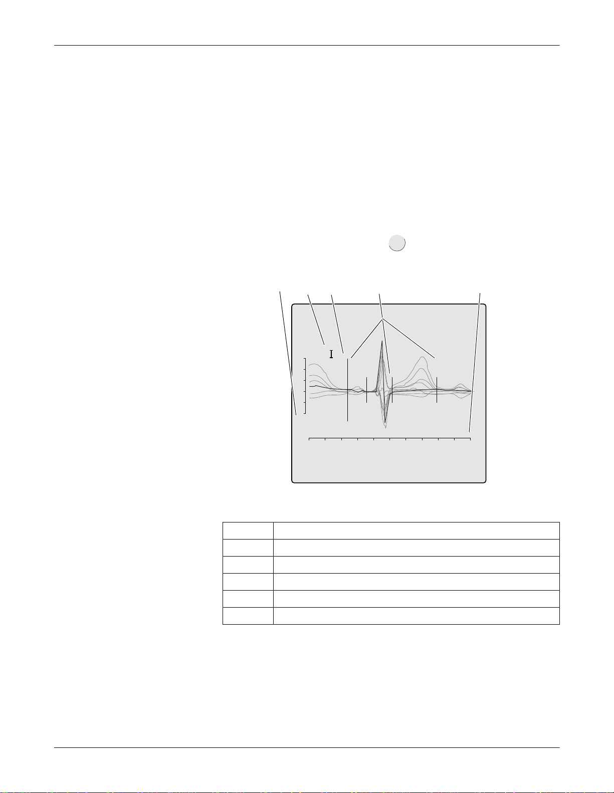
Recording in 12 Lead Mode: Adjusting Measurement Points/QT Dispersion
A
Adjusting Measurement Points/QT Dispersion
This feature is only available with MAC 1200 units equipped with the
MEAS or DIAG option. The HEART interpretation program is also
required.
Global Measurement Points
After acquisition of an ECG in the 12 Lead mode, the global
measurement points for P onset, P offset, QRS onset, QRS offset, and
T offset can be adjusted manually.
4
After acquisition of the ECG, press to display the screen for
verification of the global measurement point markers.
123 4 5
R
$
1 mV
Verification of the Global Measurement Points
1 Amplitude in [mV]
2 Selected lead
3 Active marker (large)
4 Inactive marker (small)
5 Time in [s]
1 s
028
Description
5-22 MAC 1200 Revision B
2012250-022
Page 83
Recording in 12 Lead Mode: Adjusting Measurement Points/QT Dispersion
On this displa y you wi ll see all 12 ECG lead s; the ac tive le ad is bl ack an d
displayed in the foregr ound, the inactive leads appear dimmed in the
background.
The active measurement point marker is large, the four inactive markers
are small. Use these keys to adjust the markers.
moves the active marker right or left
selects the next or previous marker
lead
activates the next lead
changes the gai n
terminates the adjustment, saving the changes
terminates the adjustment without saving the changes
space bar for the P onset and P offset values, th e space bar toggles
between definite value and approximate value.
Revision B MAC 1200 5-23
2012250-022
Page 84

Recording in 12 Lead Mode: Adjusting Measurement Points/QT Dispersion
Local T Offset Measurement Point/QT Dispersion
When you exit the screen for verification of the global measurement
points, the screen for verification of the T offset measurement point
appears automatically.
12 3 4
1 mV
1 s
Verification of the T Offset Measurement Point
Description
1 Amplitude in [mV]
2 Selected lead
3 Time in [s]
4 Active marker
Therefore, this screen always shows only one lead at a time and the T
offset point. Changing the local T offset point also affects the QT
dispersion value.
029A
5-24 MAC 1200 Revision B
2012250-022
Page 85

Recording in 12 Lead Mode: Adjusting Measurement Points/QT Dispersion
Use these keys to adjust the marker.
moves the marker right or left
lead
displays the next lead
changes the gai n
mm/mV
terminates the adjustment, saving the changes
terminates the adjustment without saving the changes
When you exit the screen, the acquisition screen for the 12 Lead mode
reappears.
The corrected ECG can be printed with the button.
lead
If the unit is equipped with the MEMO memory option, the co rrected
data can be saved (or it will be saved automatically when the
corresponding function i s enab led). If the ori gin al ECG had alrea dy be en
saved, the corrected data will overwrite this ECG.
127(
Changing the local T offset measurement point does not affect the
global T offset point.
Revision B MAC 1200 5-25
2012250-022
Page 86
Recording in 12 Lead Mode: Brief Operating Instructions – 12 Lead Mode
Brief Operating Instructions – 12 Lead Mode
Switch on the unit and wait for self-test to end.
Apply electrodes to patient.
Enter the following patient data .
Check device settings.
Report sequence
Report for m at
AC filter
Override function
12SL interpretation configuration
Modify device settings, if required .
Wait for patient to lie motionless and for the unit to collect 10
info
pat
setup
seconds of ECG data.
Check that no lead failure message is displayed.
Start recording with .
5-26 MAC 1200 Revision B
2012250-022
Page 87

6 Recording in 6 Lead
Mode
Revision B MAC 1200 6-1
2012250-022
Page 88

For your notes
6-2 MAC 1200 Revision B
2012250-022
Page 89

Recording in 6 Lead Mode: General Information
General Information
In 6 Lead mode, the system acquires six leads of ECG in real time.
Recordings are started and stopped with . Some of the system
settings can be customized. They are identified with “configurable”.
The following information refers to a unit with the system defaults. For
instructions on changing the default setup, refer to “6 Lead Mode” on
page 9-9 for details.
Report Sequence STANDARD CABRERA, SEQ.NO.4
Gain 10 mm/mV “*auto”, 5, 20, 40 mm/mV
Speed 25 mm/s 5, 50 mm/s
Muscle Filter No Yes
Table 1. Setup Menu for the 6 Lead Mode
Parameter Factory Default Options
Muscle Filter
Frequency
AC Filter Yes No
Anti-Drift System No Yes
Automatic Paper Feed Yes No
40 Hz 20 Hz
Revision B MAC 1200 6-3
2012250-022
Page 90
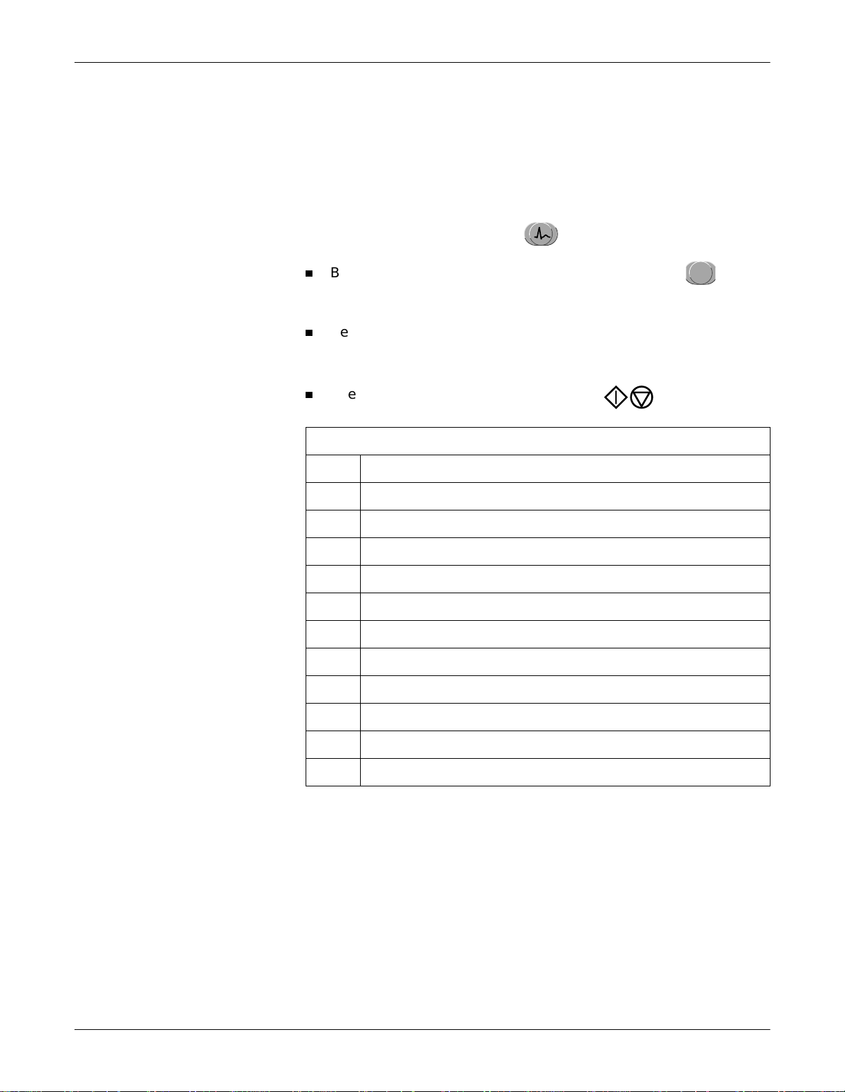
Recording
Recording in 6 Lead Mode: Recording
127(
In 6 Lead mode, messages indicating disconnected electrodes are
also annotated on the recording, e.g. Lead fail C1.
After switching on the unit, press to select 6 Lead mode.
6
Before recording the ECG, patient data can be entered ( ). It is
info
pat
recommended that you enter the patient’s name to annotate it on
every report.
Before initiating a recording, check the display for error messages (see
table below). Check all electrodes; if the mess age persi sts, there must
be a break in the patient cable. Replace the cable with a new one.
The recording is started and stopped with .
Table 2. Messages Indicating Disconnected Electrodes
*RL*: Right leg electrode disconnected
*RA*: Right arm electrode disconnected
*LA*: Left arm electrode disconnected
*LL*: Left leg electrode disconnected
*V1*: Chest electrode V1 disconnected
*V2*: Chest electrode V2 disconnected
*V3*: Chest electrode V3 disconnected
*V4*: Chest electrode V4 disconnected
*V5*: Chest electrode V5 disconnected
*V6*: Chest electrode V6 disconnected
*RL*: Right leg electrode disconnected
*RA*: Right arm electrode disconnected
6-4 MAC 1200 Revision B
2012250-022
Page 91
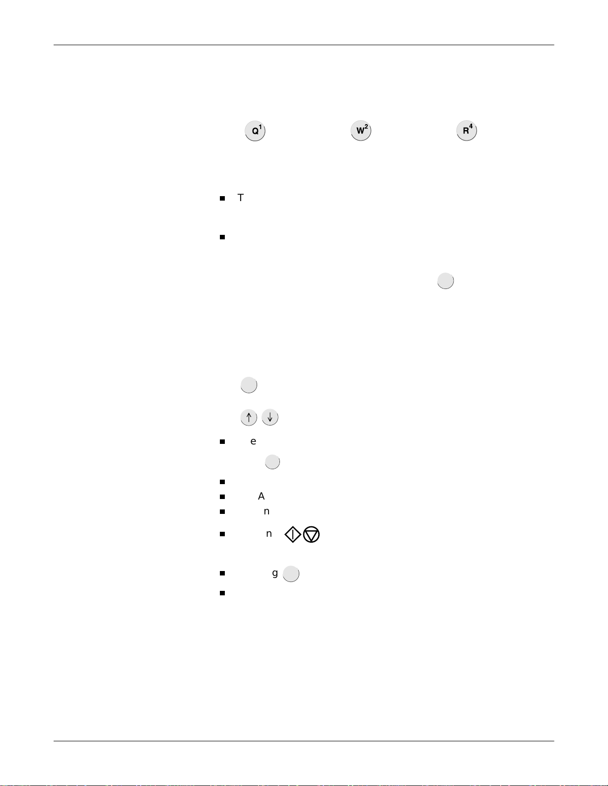
Recording in 6 Lead Mode: Recording
format/
speed
127(
In 6 Lead mode, report sequences can also be selected with these
shortcuts.
= Standard
= CABRERA
= Seq. 4
With the system defaults, the MAC 1200 will activate the following
functions and settings.
The Standard report sequence (lead to channel correspondence) : I, II,
III, aVR, aVL, aVF, V1, V2, V3, V4, V5, V6 (configurable); also
available: CABRERA, SEQ. NR. 4 (custom report sequence).
A gain of 10 mm/mV (configurable) (calibration pulse at the
beginning of the recording The unit can be set up to automatically
adapt the gain to the ECG signal (see “6 Lead Mode” on page9-9).
Also, the ga in setting can be changed with (5, 10, 20 and 40
gain
mm/mV).
127(
Please note that filters may suppress diagnostically relevant portions
of the signal, because they limit the transmission range. Filters
should therefore only be enabled if necessary.
lead
selects the other 3 leads of the selected report sequence.
display the other 3 leads of the selected group of 6.
The writer prints at a speed of 25 mm/s, the speed can be changed
with .
The muscle filter is disabled (configurable).
The AC line filter is enabled (configurable).
The anti-drift system (cubic spline) is disabled (configurable).
Pressing will not advance the paper to the next fold (Auto
Paper Feed) (configurable).
Pressing after the ECG recording will print the patient data.
The unit advances the paper to the beginning of a new page each
copy
time a recording is initiated (configurable).
Revision B MAC 1200 6-5
2012250-022
Page 92

Recording in 6 Lead Mode: Recording
lead
The locations of all relevant device settings are shown below:
Operating mode Muscle filter
Report function
2
Failure message
1
AC line filter1Anti-drift system1“Patient Name”
Gain Report sequence
Three leads
display here
3
1. if enabled
2. or REC OFF when the recording function is disabled
3. if any
Heart rate
If you change the writer speed, lea d group or any filter settings
during a recording, the unit will briefly stop.
With you advance to the next group of 6 leads of the selected
report sequence.
When the anti-drift system is enabled, there will be a short delay of
2.2 seconds before the recording starts.
The heart rate limit is automatically calculated from the date of birth
(WHO 100% = 220 - age). When the date of birth is not entered, the unit
will set the limit at 180 bpm. This value can be changed with and
(in steps of 5 bpm).
6-6 MAC 1200 Revision B
2012250-022
Page 93

7 Arrhythmia Mode
Recording
Revision B MAC 1200 7-1
2012250-022
Page 94

For your notes
7-2 MAC 1200 Revision B
2012250-022
Page 95

Arrhythmia Mode Recording: General Information
format/
speed
General Information
In Arrhythmia mode, the MAC 1200 continuously scans the ECG for
arrhythmias. From six simultaneously acquired leads, the MAC 1200
automatically selects the two that provide the best signal for analysis.
When the analysis algorithm detects an arrhythmia, the event is
recorded with “context” (see figure below). The length of the recording
varies with the duration of the event episode. In the setup menu
(Chapter 9, “System Setup” ) you determine the conditions for a
recording.
The recorder starts each time it detects a single-beat event .
The recorder starts each time i t detects an event different from the
previous event.
The recorder does not start at all.
GE marquette MAC 1200 John Doe
Event Recording
127(
After starting the program, press to select a continuous
format/
speed
recording at 5 mm/s (c). If the unit identifies an arrhythmia event, it
will automatically switch to the faster paper speed. With the same
key , the trend recording can be stopped. The unit can be set up
to automatically start a trend recording when the Arrhythmia mode
is initiated.
031A
Revision B MAC 1200 7-3
2012250-022
Page 96

Arrhythmia Mode Recording: General Information
Some of the system settings can be customize d. They a re labe led wi th
“configurable”. The following informatio n refe rs to a unit wi th th e
system defaults. For instructions on changing the default setup, refer
to “Arrhythmia Mode” on page 9-12.
Table 1. Setup Menu for the Arrhythmia Mode
Parameter Factory Default Options
Report sequence STD_C (chest
leads V1 through
V6)
STD_RED (I, II, III, V2, V4, V6)
STD_LI, (I, II, III, aVR, aVL, aVF)
CABR_LI (aVL, I, -aVR, II, aVF, III)
HIGH_C (V1’ through V6’)
Gain 10 mm/mV “*auto”, 5, 20, 40 mm/mV
Muscle Filter No Yes
Muscle Filter Frequency 40 Hz 20 Hz
AC Filter Yes No
Trend Rec. No Yes
Arrhythmia Data unequal all, no
Episodes chron. prio, ventr., no
7-4 MAC 1200 Revision B
2012250-022
Page 97

Recording
Arrhythmia Mode Recording: Recording
1. After switching on the unit, press to select the Arrhythmia
arrhy
mode.
When working with the MAC 1200 ST equipped with the Stress Test
option ERGO, you must press the button twice.
2. Before recording the ECG, patient data can be entered ( ). It is
pat
info
recommended that you enter the patient’s name to annotate it on
every report.
Before initiating a recording, check the display for error messages.
Check all electrodes; if the message persists, there must be a break
in the patient cable. Replace the cable with a new one.
3. Start and stop the recording with the key.
Table 2. Messages Indicating Disconnected Electrodes
Symbol Definition
*RL*: right leg electrode disconnected
*RA*: right arm electrode disconnected
*LA*: left arm electrode disconnected
*LL*: left leg electrode disconnected
*V1*: chest electrode V1 disconnected
*V2*: chest electrode V2 disconnected
*V3*: chest electrode V3 disconnected
*V4*: chest electrode V4 disconnected
*V5*: chest electrode V5 disconnected
*V6*: chest electrode V6 disconnected
*RL*: right leg electrode disconnected
*RA*: right arm electrode disconnected
Revision B MAC 1200 7-5
2012250-022
Page 98

During the Recording
Arrhythmia Mode Recording: Recording
When the program starts, the unit records 6 leads of ECG (1 page ).
During the following learn phase, the analysis algorithm learns the
patient’s typical QRS complex.
After the learn phase, the recorder prints a report where the QRS
complexes acquired in the learn phase are labeled L and the complex
found to be the patient’s typical complex is labeled QRSL.
When the learn phase is complete, the MAC 1200 is ready to identify
arrhythmias.
127(
With a single-page recording can be initiated after program
copy
start.
127(
Filters may suppress diagnostically relevant portions of the
signal, because they limit the transmission range. Only enable
filters if necessary.
With the system defaults, the MAC 1200 will activate the following
functions and settings.
STD_C report sequence (lead to channel correspondence) (V1 to V6)
(configurable).
Gain of 10 mm/mV (configurable) (calibration pulse at the beginning
of the recording). The unit can be set up to automatically adapt the
gain to the ECG signal (*auto).
Muscle filter is disabled (configurable).
AC line filter is enabled (configurable).
Slow trend recording is disabled (configurable).
Event episodes are recorded at a speed of 25 mm/s.
Unit documents all events that are different from the previous event
(configurable). The unit can be configured to document all events or no
events at all.
In the final report, the event episodes are printed in chronological
order.
7-6 MAC 1200 Revision B
2012250-022
Page 99

Arrhythmia Mode Recording: Recording
The locations of all relevant device settings are shown below:
Operating mode Muscle filter
Report function
2
Failure message
1
AC line filter1Anti-drift system1“Patient Name”
Gain Report sequence
Three leads
display here
3
1. if enabled
2. or REC OFF when the recording function is disabled
3. if any
Heart rate
Refer to Table 3, “Arrhythmia Codes,” on page 7-9 for an explanation of
the arrhythmia codes annotated on the recording.
The heart rate limit is automatically calculated from the date of birth
(WHO 100% = 220 - age). When the date of birth is not entered, the unit
will set the limit at 180 bpm. This value can be changed with and
(in steps of 5 bpm).
127(
The letter A on a recording indicates the presence of artifact which
does not allow the algorit hm to identi fy arrhyt hmias. Caus es include
wandering baselines. The anti-drift system largely prevents these
disturbances. Check the electrodes and leadwires.
Revision B MAC 1200 7-7
2012250-022
Page 100

Final Report
Arrhythmia Mode Recording: Recording
The arrhythmia recording can be stopped with .
Then the final report can be printed with . The final report consists
copy
of the following:
Patient ID sheet (with all patient data as well as with all analyzed
QRS complexes, type and number of det ected events and the analys is
duration in tabular form)
Episode report (3 sheets maximum with 2 episodes each Arrhythmia
codes)
7-8 MAC 1200 Revision B
2012250-022
 Loading...