

Page 1
Technical
Publications
2211157-100
Revision 0
GE Medical Systems
LOGIQ
Users Manual
CopyrightE1998 By General Electric Co.
Operating Documentation
t
α
100
Page 2

GE Medical Systems
GE Medical Systems: Telex 3797371
P.O. Box 414, Milwaukee, Wisconsin 53201 U.S.A.
(Asia, Pacific, Latin America, North America)
GE Ultrasound Europe
Kranzbuhler GmbH & Co. KG
Beethovenstr. 239
42655 Solingen, GERMANY
Page 3
Revision History
REV DATE REASON FOR CHANGE
A
0
March 28, 1998
April 15, 1998
V4.0 Initial Draft
V4.0 Release
LIST OF EFFECTIVE PAGES
PAGE REVISION PAGE REVISION
NUMBER NUMBER NUMBER NUMBER
Title Page 0
Revision History A & B 0
Regulatory Requirement 1&2 0
Table of Contents i thru x 0
Introduction 1 thru 12 0
Getting Started 13 thru 36 0
Safety 37 thru 48 0
Scan Procedures 49 thru 96 0
General Measurements
97 thru 122 0
Diagnostic Category
123 thru 128 0
OB 129 thru 218 0
Cardiology 219 thru 230 0
Urology 231 thru 234 0
Control Keys 235 thru 256 0
Probes/Biopsy 257 thru 308 0
Maintenance 309 thru 328 0
OB Tables 329 thru 384 0
Index 1 thru 8 0
LOGIQt α100 User Manual
2211 157–100 Rev 0
Revision History A
Page 4

Revision History
Please verify that you are using the latest revision of this document. Information
pertaining to this document is maintained on GPC (GE Medical Systems Global
Product Configuration). If you need to know the latest revision, contact your
distributor, local GE Sales Representative or in the USA call the GE Ultrasound
Clinical Answer Center at 1-800-682-5327 or 414-524-5186.
Revision History B
LOGIQt α100 User Manual
2211 157–100 Rev 0
Page 5

Regulatory Requirement
1. Council Directive 93/42/EEC concerning medical devices; the
label affixed to the product testifies compliance to the Directive.
The location of the CE label is documented on page 56.
European registered place of business ;
GE Medical Systems Europe
Quality Assurance Manager
BP 34
F 78533 BUC CEDEX France
Tel : (33) (0) 1 30 70 40 40
2. 510k approval for FDA (Food and Drug Administration) registration,
Department of Health, USA.
3. ETL (Electronics Testing Laboratory) certificate by ITS, based on
UL 2601–1.
4. MHW (Ministry of Health and Welfare) registration for Japan.
CAUTION United States Federal law restricts this device
to use by or on the order of a physician.
5.
General Electric Medical Systems
6. The original document was written in English.
LOGIQ α100 Users Manual
2211 157–100 Rev 0
is ISO 9001 and EN 46001 certified.
Regulatory Req 1
Page 6

Regulatory Requirement
This page left blank intentionally.
Regulatory Req 2
LOGIQ α100 Users Manual
2211157–100 Rev 0
Page 7

Table of Contents
Introduction 1. . . . . . . . . . . . . . . . . . . . . . . . . . . . . . . . . .
System Overview 3. . . . . . . . . . . . . . . . . . . . . . . . . . . . . . .
Attention 3. . . . . . . . . . . . . . . . . . . . . . . . . . . . . . . . . . . . . . . . .
Prescription Device 3. . . . . . . . . . . . . . . . . . . . . . . . . . . . . . . .
System Components 3. . . . . . . . . . . . . . . . . . . . . . . . . . . . . .
Indications for use 3. . . . . . . . . . . . . . . . . . . . . . . . . . . . . . . . .
Contraindications 3. . . . . . . . . . . . . . . . . . . . . . . . . . . . . . . . .
Overview 4. . . . . . . . . . . . . . . . . . . . . . . . . . . . . . . . . . . . . . . .
System Specifications 5. . . . . . . . . . . . . . . . . . . . . . . . . .
Standard Specifications 5. . . . . . . . . . . . . . . . . . . . . . . . . . . .
Standard Configuration 7. . . . . . . . . . . . . . . . . . . . . . . . . . . .
System Description 8. . . . . . . . . . . . . . . . . . . . . . . . . . . . . . . .
Front View 8. . . . . . . . . . . . . . . . . . . . . . . . . . . . . . . . . . . .
Side View 9. . . . . . . . . . . . . . . . . . . . . . . . . . . . . . . . . . . .
Rear View 10. . . . . . . . . . . . . . . . . . . . . . . . . . . . . . . . . . . .
Peripherals/Accessories 12. . . . . . . . . . . . . . . . . . . . . . . . . . .
Optional Accessories 12. . . . . . . . . . . . . . . . . . . . . . . . . .
Getting Started 13. . . . . . . . . . . . . . . . . . . . . . . . . . . . . . . .
Preparing the System for Use 15. . . . . . . . . . . . . . . . . . . .
Overview 15. . . . . . . . . . . . . . . . . . . . . . . . . . . . . . . . . . . . . . . .
Local Site Requirements 15. . . . . . . . . . . . . . . . . . . . . . . . . . .
Before the system arrives 15. . . . . . . . . . . . . . . . . . . . . .
Environmental Requirements 16. . . . . . . . . . . . . . . . . . .
Connecting and Using the System 17. . . . . . . . . . . . . . . . . . .
Keyboard Preparation 17. . . . . . . . . . . . . . . . . . . . . . . . . .
Power Cord 17. . . . . . . . . . . . . . . . . . . . . . . . . . . . . . . . . . .
Circuit Breaker 19. . . . . . . . . . . . . . . . . . . . . . . . . . . . . . . .
Foot Switch Connection (Optional) 19. . . . . . . . . . . . . . . . . .
Power ON/OFF 20. . . . . . . . . . . . . . . . . . . . . . . . . . . . . . . . . . .
Power ON Process 20. . . . . . . . . . . . . . . . . . . . . . . . . . . .
Power Off Process 21. . . . . . . . . . . . . . . . . . . . . . . . . . . . .
Probe Connection 22. . . . . . . . . . . . . . . . . . . . . . . . . . . . . . . . .
Connecting a probe 22. . . . . . . . . . . . . . . . . . . . . . . . . . . .
Disconnecting a probe 23. . . . . . . . . . . . . . . . . . . . . . . . .
Probe Storage 23. . . . . . . . . . . . . . . . . . . . . . . . . . . . . . . .
Adjustment of Monitor Contrast and Brightness 24. . . . . . .
Connection of Peripherals and Accessories 25. . . . . . . . . .
LOGIQ α100 Users Manual
2211 157–100 Rev 0
Table of Contents i
Page 8

Table of Contents
Operator Controls 27. . . . . . . . . . . . . . . . . . . . . . . . . . . . . .
Keyboard Controls 27. . . . . . . . . . . . . . . . . . . . . . . . . . . . . . . .
Keyboard Layout 27. . . . . . . . . . . . . . . . . . . . . . . . . . . . . .
Key Description 28. . . . . . . . . . . . . . . . . . . . . . . . . . . . . . .
System Setup 33. . . . . . . . . . . . . . . . . . . . . . . . . . . . . . . . . .
Setup Procedure 33. . . . . . . . . . . . . . . . . . . . . . . . . . . . . . . . . .
Relocating the System 35. . . . . . . . . . . . . . . . . . . . . . . . . .
Moving the system 35. . . . . . . . . . . . . . . . . . . . . . . . . . . . . . . .
Transporting the system 36. . . . . . . . . . . . . . . . . . . . . . . . . . .
Safety 37. . . . . . . . . . . . . . . . . . . . . . . . . . . . . . . . . . . . . . . .
Precaution Levels 39. . . . . . . . . . . . . . . . . . . . . . . . . . . . . . .
Overview 39. . . . . . . . . . . . . . . . . . . . . . . . . . . . . . . . . . . . . . . .
Icon Description 39. . . . . . . . . . . . . . . . . . . . . . . . . . . . . . . . . .
Hazard Symbols 41. . . . . . . . . . . . . . . . . . . . . . . . . . . . . . . .
Icon Description 41. . . . . . . . . . . . . . . . . . . . . . . . . . . . . . . . . .
Important Safety Considerations 42. . . . . . . . . . . . . . . . . . . .
Patient Safety 43. . . . . . . . . . . . . . . . . . . . . . . . . . . . . . . . . .
Related Hazards 43. . . . . . . . . . . . . . . . . . . . . . . . . . . . . . . . . .
Equipment and Personnel Safety 47. . . . . . . . . . . . . . . .
Related Hazards 47. . . . . . . . . . . . . . . . . . . . . . . . . . . . . . . . . .
Device Labels 49. . . . . . . . . . . . . . . . . . . . . . . . . . . . . . . . . .
Label Icon Description 49. . . . . . . . . . . . . . . . . . . . . . . . . . . . .
Classifications 51. . . . . . . . . . . . . . . . . . . . . . . . . . . . . . . . . . . .
EMC – Electromagnetic Compatibility 51. . . . . . . . . . . . . . . .
Warning Labels/Locations 55. . . . . . . . . . . . . . . . . . . . . . .
Warning Labels 55. . . . . . . . . . . . . . . . . . . . . . . . . . . . . . . . . . .
Scan Procedures 59. . . . . . . . . . . . . . . . . . . . . . . . . . . . . .
Patient Registration 61. . . . . . . . . . . . . . . . . . . . . . . . . . . . .
Introduction 61. . . . . . . . . . . . . . . . . . . . . . . . . . . . . . . . . . . . . .
Patient Registration Procedure 61. . . . . . . . . . . . . . . . . . . . .
Patient Scan Procedure 62. . . . . . . . . . . . . . . . . . . . . . . .
Image Display 65. . . . . . . . . . . . . . . . . . . . . . . . . . . . . . . . . .
Overview 65. . . . . . . . . . . . . . . . . . . . . . . . . . . . . . . . . . . . . . . .
*B/A-Mode 66. . . . . . . . . . . . . . . . . . . . . . . . . . . . . . . . . . .
B-Mode 67. . . . . . . . . . . . . . . . . . . . . . . . . . . . . . . . . . . . . .
B/M-Mode 69. . . . . . . . . . . . . . . . . . . . . . . . . . . . . . . . . . . .
M-Mode 70. . . . . . . . . . . . . . . . . . . . . . . . . . . . . . . . . . . . . .
Multiple Image Display 71. . . . . . . . . . . . . . . . . . . . . . . . .
Table of Contents ii
LOGIQ α100 Users Manual
2211157–100 Rev 0
Page 9

Table of Contents
Scan Adjustments 73. . . . . . . . . . . . . . . . . . . . . . . . . . . . . .
Near and Far Gain 73. . . . . . . . . . . . . . . . . . . . . . . . . . . . . . . .
Dynamic Range 73. . . . . . . . . . . . . . . . . . . . . . . . . . . . . . . . . . .
Focus Selections 74. . . . . . . . . . . . . . . . . . . . . . . . . . . . . . . . . .
Gain/Rotate 74. . . . . . . . . . . . . . . . . . . . . . . . . . . . . . . . . . . . . .
Depth Key 74. . . . . . . . . . . . . . . . . . . . . . . . . . . . . . . . . . . . . . .
Preset Parameter 75. . . . . . . . . . . . . . . . . . . . . . . . . . . . . . . . .
Image Reverse/Image Inverse Key 76. . . . . . . . . . . . . . . . . .
Scroll 76. . . . . . . . . . . . . . . . . . . . . . . . . . . . . . . . . . . . . . . . . . . .
Freezing an Image 77. . . . . . . . . . . . . . . . . . . . . . . . . . . . . . . .
Annotating the Image 77. . . . . . . . . . . . . . . . . . . . . . . . . . . . . .
Erasing Annotations 77. . . . . . . . . . . . . . . . . . . . . . . . . . .
Body Patterns 78. . . . . . . . . . . . . . . . . . . . . . . . . . . . . . . . . . . .
Selection Key 78. . . . . . . . . . . . . . . . . . . . . . . . . . . . . . . . .
Rotate Keys 82. . . . . . . . . . . . . . . . . . . . . . . . . . . . . . . . . .
VCR Operations 83. . . . . . . . . . . . . . . . . . . . . . . . . . . . . . . .
Overview 83. . . . . . . . . . . . . . . . . . . . . . . . . . . . . . . . . . . . . . . .
External Video 83. . . . . . . . . . . . . . . . . . . . . . . . . . . . . . . . . . . .
Record 83. . . . . . . . . . . . . . . . . . . . . . . . . . . . . . . . . . . . . . . . . .
Two Probe Port (Option) 85. . . . . . . . . . . . . . . . . . . . . . . . .
Description 85. . . . . . . . . . . . . . . . . . . . . . . . . . . . . . . . . . . . . . .
Right Side View 85. . . . . . . . . . . . . . . . . . . . . . . . . . . . . . .
Left Side View 86. . . . . . . . . . . . . . . . . . . . . . . . . . . . . . . .
Orientation of the Two Probe Port Module on the system 87
Connecting the Two Probe Port 88. . . . . . . . . . . . . . . . . . . . .
Connecting Probes to the Two Probe Port Option 90. . . . .
Connecting Probes to the Two Probe Port Option 90. . . . .
Connecting a Second Probe 92. . . . . . . . . . . . . . . . . . . .
Switching Probes 93. . . . . . . . . . . . . . . . . . . . . . . . . . . . . . . . .
Presetting Parameters to a Probe 94. . . . . . . . . . . . . . . . . . .
Power ON with Two Probe Port 95. . . . . . . . . . . . . . . . . . . . .
Disconnecting a Probe from the Two Probe Port 95. . . . . .
Disconnecting the Two Probe Port 96. . . . . . . . . . . . . . . . . . .
General Measurements 97. . . . . . . . . . . . . . . . . . . . . . .
Basic Measurements 99. . . . . . . . . . . . . . . . . . . . . . . . . . . .
Overview 99. . . . . . . . . . . . . . . . . . . . . . . . . . . . . . . . . . . . . . . .
General Instructions 99. . . . . . . . . . . . . . . . . . . . . . . . . . . . . . .
Measurement Accuracy 100. . . . . . . . . . . . . . . . . . . . . . . . . . . .
Erasing Measurements 101. . . . . . . . . . . . . . . . . . . . . . . . . . . .
Measurement Key 101. . . . . . . . . . . . . . . . . . . . . . . . . . . . . . . . .
Cursors 101. . . . . . . . . . . . . . . . . . . . . . . . . . . . . . . . . . . . . . . . . .
General Measurement Menu 102. . . . . . . . . . . . . . . . . . . . . . .
Distance Measurement 103. . . . . . . . . . . . . . . . . . . . . . . . . . . .
*Distance Measurement in B/A Mode 104. . . . . . . . . . . .
Circumference/Area Measurement 105. . . . . . . . . . . . . . . . . .
LOGIQ α100 Users Manual
2211 157–100 Rev 0
Table of Contents iii
Page 10

Table of Contents
Two Distance Method 105. . . . . . . . . . . . . . . . . . . . . . . . . .
Ellipse Method 107. . . . . . . . . . . . . . . . . . . . . . . . . . . . . . . .
Alternate Ellipse Method 108. . . . . . . . . . . . . . . . . . . . . . .
Trace Method 109. . . . . . . . . . . . . . . . . . . . . . . . . . . . . . . . .
Volume Measurement 110. . . . . . . . . . . . . . . . . . . . . . . . . . . . .
Overview 110. . . . . . . . . . . . . . . . . . . . . . . . . . . . . . . . . . . . .
Pre and Post Selection Procedures 112. . . . . . . . . . . . .
Measurement of Volume by approximation to a Sphere
(One Distance Method) 113. . . . . . . . . . . . . . . . . . . .
Measurement of Volume by approximation to a Prolate Spheroid
(Two Distance Method) 114. . . . . . . . . . . . . . . . . . . .
Measurement of Volume by approximation to a Spheroid
(Three Distance Method) 116. . . . . . . . . . . . . . . . . . .
Heart Rate measurement 118. . . . . . . . . . . . . . . . . . . . . . . . . .
Velocity Measurement 119. . . . . . . . . . . . . . . . . . . . . . . . . . . . .
A/B Ratio 120. . . . . . . . . . . . . . . . . . . . . . . . . . . . . . . . . . . . . . . .
Time Measurement 121. . . . . . . . . . . . . . . . . . . . . . . . . . . . . . . .
Biopsy Depth Measurement 122. . . . . . . . . . . . . . . . . . . . . . . .
Diagnostic Category 123. . . . . . . . . . . . . . . . . . . . . . . . . . .
Diagnostic Category 125. . . . . . . . . . . . . . . . . . . . . . . . . . . .
Overview 125. . . . . . . . . . . . . . . . . . . . . . . . . . . . . . . . . . . . . . . .
Abdomen 125. . . . . . . . . . . . . . . . . . . . . . . . . . . . . . . . . . . . . . . .
Obstetrics 126. . . . . . . . . . . . . . . . . . . . . . . . . . . . . . . . . . . . . . . .
Gynecology 126. . . . . . . . . . . . . . . . . . . . . . . . . . . . . . . . . . . . . .
Cardiology 127. . . . . . . . . . . . . . . . . . . . . . . . . . . . . . . . . . . . . . .
Urology 127. . . . . . . . . . . . . . . . . . . . . . . . . . . . . . . . . . . . . . . . . .
Selecting a Diagnostic Category 128. . . . . . . . . . . . . . . . . . . .
OB 129. . . . . . . . . . . . . . . . . . . . . . . . . . . . . . . . . . . . . . . . . . .
Exam Preparation 131. . . . . . . . . . . . . . . . . . . . . . . . . . . . . . .
Overview 131. . . . . . . . . . . . . . . . . . . . . . . . . . . . . . . . . . . . . . . .
OB Measurements 133. . . . . . . . . . . . . . . . . . . . . . . . . . . . . .
Overview 133. . . . . . . . . . . . . . . . . . . . . . . . . . . . . . . . . . . . . . . .
Measurement Version Selection 134. . . . . . . . . . . . . . . . . . . . .
Available Measurements 134. . . . . . . . . . . . . . . . . . . . . . . . . . .
Standard Procedures 136. . . . . . . . . . . . . . . . . . . . . . . . . . . . . .
Table of Contents iv
LOGIQ α100 Users Manual
2211157–100 Rev 0
Page 11

Table of Contents
OB Measurement Procedures 136. . . . . . . . . . . . . . . . . . . . . .
A/B Ratio 136. . . . . . . . . . . . . . . . . . . . . . . . . . . . . . . . . . . . .
Abdominal Circumference (AC) 137. . . . . . . . . . . . . . . . .
Amniotic Fluid Index (AFI) 139. . . . . . . . . . . . . . . . . . . . . .
Anteroposterior Trunk Diameter & Transverse Trunk Diameter
(APTD & TTD) 141. . . . . . . . . . . . . . . . . . . . . . . . . . . .
Binocular Distance (BD) 143. . . . . . . . . . . . . . . . . . . . . . . .
Biparietal Diameter (BPD) 144. . . . . . . . . . . . . . . . . . . . . .
Circumference & Area 145. . . . . . . . . . . . . . . . . . . . . . . . .
Crown Rump Length (CRL) 146. . . . . . . . . . . . . . . . . . . . .
Estimated Date of Confinement (EDC/EDD) 147. . . . . .
Estimated Fetal Weight (EFW) - U.S. and Australia 148
Estimated Fetal Body Weight (EFBW) -
Tokyo University 151. . . . . . . . . . . . . . . . . . . . . . . . . . . . . . .
Estimated Fetal Body Weight (EFBW) -
Osaka University 151. . . . . . . . . . . . . . . . . . . . . . . . . . . . . .
Estimated Fetal Weight (EFW) - European 152. . . . . . . .
Femur Length (FL) 155. . . . . . . . . . . . . . . . . . . . . . . . . . . .
Fetal Trunk Cross Sectional Area (FTA) 156. . . . . . . . . .
Foot Distance (Ft) 158. . . . . . . . . . . . . . . . . . . . . . . . . . . . .
Gestational Sac (GS) 159. . . . . . . . . . . . . . . . . . . . . . . . . .
Head Circumference (HC) 160. . . . . . . . . . . . . . . . . . . . . .
HIP Dysplasia (HIP) 162. . . . . . . . . . . . . . . . . . . . . . . . . . .
Hip Measurement with Cranial Left Orientation 163. . . . . . . .
Hip Measurement with Caudal Left Orientation 164. . . . . . . .
Humerus Bone Length (HL) 165. . . . . . . . . . . . . . . . . . . . .
Heart Rate (Beats per minute) 166. . . . . . . . . . . . . . . . . .
Length of Vertebra (LV) 167. . . . . . . . . . . . . . . . . . . . . . . .
Occipito Frontal Diameter (OFD) 168. . . . . . . . . . . . . . . .
Transverse Abdominal Diameter (TAD) 169. . . . . . . . . . .
Velocity (mm/second) 170. . . . . . . . . . . . . . . . . . . . . . . . . .
Volume (cm3) 171. . . . . . . . . . . . . . . . . . . . . . . . . . . . . . . . .
Calculation Error Messages 171. . . . . . . . . . . . . . . . . . . . .
OB Report Page 173. . . . . . . . . . . . . . . . . . . . . . . . . . . . . . . .
Overview 173. . . . . . . . . . . . . . . . . . . . . . . . . . . . . . . . . . . . . . . .
Displaying and Exiting the Report Page 173. . . . . . . . . . . . . .
Edit Fields 174. . . . . . . . . . . . . . . . . . . . . . . . . . . . . . . . . . . . . . .
Hardcopy Output of the Report Page 174. . . . . . . . . . . . . . . .
Report Page Format 175. . . . . . . . . . . . . . . . . . . . . . . . . . . . . . .
U.S. Version Report Page 175. . . . . . . . . . . . . . . . . . . . . .
Tokyo University Report Page 184. . . . . . . . . . . . . . . . . . .
Osaka University Report Page 189. . . . . . . . . . . . . . . . . .
European Version Report Page 192. . . . . . . . . . . . . . . . .
Australian Version Report Page 199. . . . . . . . . . . . . . . . .
LOGIQ α100 Users Manual
2211 157–100 Rev 0
Table of Contents v
Page 12

Table of Contents
Measurement Averaging Page 200. . . . . . . . . . . . . . . . . . . . . .
Overview 200. . . . . . . . . . . . . . . . . . . . . . . . . . . . . . . . . . . . .
U.S. and Australian Versions 201. . . . . . . . . . . . . . . . . . .
Tokyo University Version 202. . . . . . . . . . . . . . . . . . . . . . .
Osaka University Version 203. . . . . . . . . . . . . . . . . . . . . . .
European Version 204. . . . . . . . . . . . . . . . . . . . . . . . . . . . .
Editing the Measurement Averaging Page 205. . . . . . . . . . . .
Average All 205. . . . . . . . . . . . . . . . . . . . . . . . . . . . . . . . . . .
Anatomical Survey Page 206. . . . . . . . . . . . . . . . . . . . . . . . . . .
Overview 206. . . . . . . . . . . . . . . . . . . . . . . . . . . . . . . . . . . . .
Editing the Anatomical Survey Page 207. . . . . . . . . . . . .
User Features 207. . . . . . . . . . . . . . . . . . . . . . . . . . . . . . . .
OB User Table 209. . . . . . . . . . . . . . . . . . . . . . . . . . . . . . . . . .
Overview 209. . . . . . . . . . . . . . . . . . . . . . . . . . . . . . . . . . . . . . . .
Specifications 209. . . . . . . . . . . . . . . . . . . . . . . . . . . . . . . . . . . .
The OB User Table 210. . . . . . . . . . . . . . . . . . . . . . . . . . . . . . . .
Entering an OB Table 211. . . . . . . . . . . . . . . . . . . . . . . . . . . . . .
Identifying the Statistical Type 211. . . . . . . . . . . . . . . . . . .
Choosing the Statistical Expression of Output (CGA) 211
Copying data from Data Sheet to System 215. . . . . . . . .
Linear Interpolation 216. . . . . . . . . . . . . . . . . . . . . . . . . . . . . . . .
Measurement with User Tables 216. . . . . . . . . . . . . . . . . . . . .
Invoking the Report Page 217. . . . . . . . . . . . . . . . . . . . . . . . . .
Erasing a User Table 218. . . . . . . . . . . . . . . . . . . . . . . . . . . . . .
Cardiology 219. . . . . . . . . . . . . . . . . . . . . . . . . . . . . . . . . . . .
Cardiac Measurements 221. . . . . . . . . . . . . . . . . . . . . . . . . .
Cardiology Diagnostic Category 221. . . . . . . . . . . . . . . . . . . . .
Measurements 222. . . . . . . . . . . . . . . . . . . . . . . . . . . . . . . . . . . .
Cardiology Menu 223. . . . . . . . . . . . . . . . . . . . . . . . . . . . . . . . . .
Amplitude measurement 224. . . . . . . . . . . . . . . . . . . . . . . . . . .
Volume (cm3) 225. . . . . . . . . . . . . . . . . . . . . . . . . . . . . . . . . . . .
Basic Measurements in Cardiology Menu 225. . . . . . . . . . . .
Left Ventricle Function Measurement 226. . . . . . . . . . . . . . . .
LV End Diastolic Volume (EDV) 226. . . . . . . . . . . . . . . . .
LV End Systolic Volume (ESV) 226. . . . . . . . . . . . . . . . . .
Cubed formula 226. . . . . . . . . . . . . . . . . . . . . . . . . . . . . . . .
Teichholz formula 227. . . . . . . . . . . . . . . . . . . . . . . . . . . . . .
Stroke Volume (SV) 227. . . . . . . . . . . . . . . . . . . . . . . . . . . .
Ejection fraction (EF) 227. . . . . . . . . . . . . . . . . . . . . . . . . .
Cardiac output (CO) 227. . . . . . . . . . . . . . . . . . . . . . . . . . .
Measurement of LV Functions 228. . . . . . . . . . . . . . . . . . . . . .
Substitution of a LV measurement 230. . . . . . . . . . . . . . . . . . .
Table of Contents vi
LOGIQ α100 Users Manual
2211157–100 Rev 0
Page 13

Urology 231. . . . . . . . . . . . . . . . . . . . . . . . . . . . . . . . . . . . . .
Urology 233. . . . . . . . . . . . . . . . . . . . . . . . . . . . . . . . . . . . . . . .
Overview 233. . . . . . . . . . . . . . . . . . . . . . . . . . . . . . . . . . . . . . . .
Urology Report Page 234. . . . . . . . . . . . . . . . . . . . . . . . . . . . . .
Control Keys 235. . . . . . . . . . . . . . . . . . . . . . . . . . . . . . . . . .
Configuration Using Control Keys 237. . . . . . . . . . . . . . .
Frame Averaging 238. . . . . . . . . . . . . . . . . . . . . . . . . . . . . . . . .
Biopsy Zone Display ON/OFF 239. . . . . . . . . . . . . . . . . . . . . .
Home Position for Comment 240. . . . . . . . . . . . . . . . . . . . . . . .
Diagnostic Category 241. . . . . . . . . . . . . . . . . . . . . . . . . . . . . . .
Body Patterns 242. . . . . . . . . . . . . . . . . . . . . . . . . . . . . . . . . . . .
Erasing OB User Table 243. . . . . . . . . . . . . . . . . . . . . . . . . . . .
Factory Default Settings 244. . . . . . . . . . . . . . . . . . . . . . . . . . .
Help for Control and Direct Keys 245. . . . . . . . . . . . . . . . . . . .
Biopsy Zone Change 247. . . . . . . . . . . . . . . . . . . . . . . . . . . . . .
*B/A-Mode 248. . . . . . . . . . . . . . . . . . . . . . . . . . . . . . . . . . . . . . .
Report Page Display 249. . . . . . . . . . . . . . . . . . . . . . . . . . . . . .
Setup Menu 250. . . . . . . . . . . . . . . . . . . . . . . . . . . . . . . . . . . . . .
Text/Graphic Display On/Off 252. . . . . . . . . . . . . . . . . . . . . . . .
Preset Probe Parameters 253. . . . . . . . . . . . . . . . . . . . . . . . . .
Map Curve Selection 254. . . . . . . . . . . . . . . . . . . . . . . . . . . . . .
Gray Scale Map 255. . . . . . . . . . . . . . . . . . . . . . . . . . . . . . .
Table of Contents
Probes/Biopsy 257. . . . . . . . . . . . . . . . . . . . . . . . . . . . . . . .
Probes 259. . . . . . . . . . . . . . . . . . . . . . . . . . . . . . . . . . . . . . . . .
Kinds of Probes 259. . . . . . . . . . . . . . . . . . . . . . . . . . . . . . . . . . .
Usage of the Probes 259. . . . . . . . . . . . . . . . . . . . . . . . . . . . . . .
Depth Details 259. . . . . . . . . . . . . . . . . . . . . . . . . . . . . . . . . . . . .
Care and Maintenance 260. . . . . . . . . . . . . . . . . . . . . . . . . . . . .
Inspecting probes 260. . . . . . . . . . . . . . . . . . . . . . . . . . . . .
Storing probes 260. . . . . . . . . . . . . . . . . . . . . . . . . . . . . . . .
Transporting probes 260. . . . . . . . . . . . . . . . . . . . . . . . . . .
Environmental Requirements 260. . . . . . . . . . . . . . . . . . .
Probe Safety 261. . . . . . . . . . . . . . . . . . . . . . . . . . . . . . . . . . . . .
Handling precautions 261. . . . . . . . . . . . . . . . . . . . . . . . . .
Electrical shock hazard 261. . . . . . . . . . . . . . . . . . . . . . . . .
Mechanical hazards 262. . . . . . . . . . . . . . . . . . . . . . . . . . .
Special handling instructions 262. . . . . . . . . . . . . . . . . . . .
Probe handling and infection control 263. . . . . . . . . . . . . . . . .
Probe Cleaning Process 263. . . . . . . . . . . . . . . . . . . . . . . .
Disinfecting probes 265. . . . . . . . . . . . . . . . . . . . . . . . . . . .
Coupling gels 267. . . . . . . . . . . . . . . . . . . . . . . . . . . . . . . . . . . . .
Planned Maintenance 267. . . . . . . . . . . . . . . . . . . . . . . . . . . . .
LOGIQ α100 Users Manual
2211 157–100 Rev 0
Table of Contents vii
Page 14

Table of Contents
Acoustic Output 268. . . . . . . . . . . . . . . . . . . . . . . . . . . . . . . . . . .
Control Parameters which Affect Acoustic Sound 268. .
Acoustic Level Notes 269. . . . . . . . . . . . . . . . . . . . . . . . . .
Measurement Basis for Probe Output 270. . . . . . . . . . . .
Acoustic Output Tables 270. . . . . . . . . . . . . . . . . . . . . . . . . . . .
Probe: C36 270. . . . . . . . . . . . . . . . . . . . . . . . . . . . . . . . . . .
Probe: C55 271. . . . . . . . . . . . . . . . . . . . . . . . . . . . . . . . . . .
Probe: L76 271. . . . . . . . . . . . . . . . . . . . . . . . . . . . . . . . . . .
Probe: E72 272. . . . . . . . . . . . . . . . . . . . . . . . . . . . . . . . . . .
Probe: C31 272. . . . . . . . . . . . . . . . . . . . . . . . . . . . . . . . . . .
Probe VE5 273. . . . . . . . . . . . . . . . . . . . . . . . . . . . . . . . . . .
Symbol Description 273. . . . . . . . . . . . . . . . . . . . . . . . . . . .
IEC Acoustic Output Tables 274. . . . . . . . . . . . . . . . . . . . . . . .
Key to Tables 274. . . . . . . . . . . . . . . . . . . . . . . . . . . . . . . . .
Probe: C36 276. . . . . . . . . . . . . . . . . . . . . . . . . . . . . . . . . . .
Probe: C55 277. . . . . . . . . . . . . . . . . . . . . . . . . . . . . . . . . . .
Probe: L76 278. . . . . . . . . . . . . . . . . . . . . . . . . . . . . . . . . . .
Probe: E72 279. . . . . . . . . . . . . . . . . . . . . . . . . . . . . . . . . . .
Probe: C31 280. . . . . . . . . . . . . . . . . . . . . . . . . . . . . . . . . . .
Probe: VE5 281. . . . . . . . . . . . . . . . . . . . . . . . . . . . . . . . . . .
Biopsy Procedures 283. . . . . . . . . . . . . . . . . . . . . . . . . . . . .
Special Concerns 283. . . . . . . . . . . . . . . . . . . . . . . . . . . . . . . . .
Precautions Concerning the
Use of Biopsy Procedures 283. . . . . . . . . . . . . . . . . . . . . .
Accessories and Supplies 284. . . . . . . . . . . . . . . . . . . . . . . . . .
Required supplies 284. . . . . . . . . . . . . . . . . . . . . . . . . . . . .
Biopsy Procedure 285. . . . . . . . . . . . . . . . . . . . . . . . . . . . . . . . .
Displaying Biopsy Guidelines 285. . . . . . . . . . . . . . . . . . .
Needle Guide Type Preset 288. . . . . . . . . . . . . . . . . . . . . . . . .
Biopsy Guide Attachment 290. . . . . . . . . . . . . . . . . . . . . . . . . .
Fixed Needle Guide Assembly 290. . . . . . . . . . . . . . . . . .
Fixed Needle Guide Assembly (cont’d) 293. . . . . . . . . . .
The Procedure 301. . . . . . . . . . . . . . . . . . . . . . . . . . . . . . . . . . . .
Post Biopsy 301. . . . . . . . . . . . . . . . . . . . . . . . . . . . . . . . . . .
E72 Probe Biopsy Guide 302. . . . . . . . . . . . . . . . . . . . . . . . . . .
Preparation 302. . . . . . . . . . . . . . . . . . . . . . . . . . . . . . . . . . .
Scanning 305. . . . . . . . . . . . . . . . . . . . . . . . . . . . . . . . . . . . .
Post Biopsy 306. . . . . . . . . . . . . . . . . . . . . . . . . . . . . . . . . . .
Biopsy Probes 307. . . . . . . . . . . . . . . . . . . . . . . . . . . . . . . . . . . .
Table of Contents viii
LOGIQ α100 Users Manual
2211157–100 Rev 0
Page 15

Troubleshooting and Maintenance 309. . . . . . . . . . . . .
Troubleshooting 311. . . . . . . . . . . . . . . . . . . . . . . . . . . . . . . .
Overview 311. . . . . . . . . . . . . . . . . . . . . . . . . . . . . . . . . . . . . . . .
Troubleshooting the LOGIQ a100 311. . . . . . . . . . . . . . . . . .
Troubleshooting the Videographic Printer (Option) 312. . . . .
Who To Contact 313. . . . . . . . . . . . . . . . . . . . . . . . . . . . . . . . . . .
Manufacturer 316. . . . . . . . . . . . . . . . . . . . . . . . . . . . . . . . . . . . .
Maintenance 317. . . . . . . . . . . . . . . . . . . . . . . . . . . . . . . . . . . .
Overview 317. . . . . . . . . . . . . . . . . . . . . . . . . . . . . . . . . . . . . . . .
Inspecting the System 317. . . . . . . . . . . . . . . . . . . . . . . . . . . . .
Daily Check List 317. . . . . . . . . . . . . . . . . . . . . . . . . . . . . . .
Weekly Check List 318. . . . . . . . . . . . . . . . . . . . . . . . . . . . .
Monthly Check List 320. . . . . . . . . . . . . . . . . . . . . . . . . . . .
Trackball Maintenance 321. . . . . . . . . . . . . . . . . . . . . . . . . . . . .
Removal of the Retainer Ring 322. . . . . . . . . . . . . . . . . . .
Cleaning the Trackball 324. . . . . . . . . . . . . . . . . . . . . . . . .
Fixing the Trackball and Retainer Ring 325. . . . . . . . . . .
Planned Maintenance 327. . . . . . . . . . . . . . . . . . . . . . . . . . . . .
OB Tables 329. . . . . . . . . . . . . . . . . . . . . . . . . . . . . . . . . . . .
Table of Contents
OB Tables 331. . . . . . . . . . . . . . . . . . . . . . . . . . . . . . . . . . . . . .
Index Index I. . . . . . . . . . . . . . . . . . . . . . . . . . . . . . . . . . . . . . . . .
LOGIQ α100 Users Manual
2211 157–100 Rev 0
Table of Contents ix
Page 16

Table of Contents
This page left blank intentionally.
Table of Contents x
LOGIQ α100 Users Manual
2211157–100 Rev 0
Page 17

Introduction
System Overview
System Specifications
This section provides a basic description of the LOGIQ α100 system’s
features and benefits.
LOGIQt α100 User Manual
2211 157–100 Rev 0
1
Page 18

Introduction
This page left blank intentionally.
2
LOGIQt α100 User Manual
2211 157–100 Rev 0
Page 19

Attention
Read and understand all instructions in this manual
before attempting to use the LOGIQ α100 System.
Keep this User’s Manual with the equipment at all times.
Periodically review the procedures for operation and
safety precautions.
Prescription Device
System Overview
.
FOR USA
ONLY
Caution: United States law restricts this device to
sale or use by or on the order of a physician.
System Components
.
Refer to the Service Manual (2139768) for
LOGIQ α100 System components.
Indications for use
The LOGIQ α100 is intended for use in obstetrical,
gynecological, abdominal, urology, cardiology and small
parts applications.
Contraindications
Do NOT use the system for Ophthalmic applications (or
any use causing the acoustic beam to pass through the
eye).
LOGIQt α100 User Manual
2211 157–100 Rev 0
3
Page 20

System Overview
Overview
The GE Medical Systems LOGIQ α100 portable
ultrasound scanner is a system designed for OB/GYN,
Abdomen, Urology, Cardiology and Small part scans
using the convex, linear and micro convex probes. The
system provides image generation in B-Mode, M-Mode,
A-Mode(India only), Dual B-Mode and B/M-Mode. High
quality images can be obtained by the proper selection of
scan control parameters. The diagnostic capability is
further enhanced by the different measurement and
calculation packages available in the system.
All probes are precise solid state array devices, allowing
electronically controlled imaging with Convex,
Micro-convex and Linear probes. Use of solid state
digital designs allows a wide variety of scan parameters
to be optimized resulting in consistent generation of
finely detailed anatomical resolution with excellent
dynamic contrast tissue range and penetration.
The System has a sophisticated console design featuring
multiple diagnostic functions and preset function keys.
This makes the system user friendly and easy to use.
4
LOGIQt α100 User Manual
2211 157–100 Rev 0
Page 21
Standard Specifications
System Specifications
System Configuration
S
Console with Keyboard
S
Probe/Gel Holder (Removable)
S
Probe (user selectable)
S
Power Cord
S
Probe Pad
S
Gel Bottle
S
Trackball Cleaning Kit
System Dimensions
S
Height : 244 mm (9.6 inches)
S
Width : 276 mm (10.9 inches)
S
Depth : 405 mm (15.9 inches)
Weight
S
9.8 Kg (Without Probe)
Electrical Power
S
Power Supply:
220/240V∼ 50/60 Hz, 170 VA Max,
Single Phase
100/1 15V ∼ 50/60 Hz, 140 VA Max,
Single Phase
Scanning
Probe Types
S
C36 – 3.5 MHz Convex Array
(FOV: 68_, ROC: 50 mm)
S
C55 – 5 MHz Convex Array
(FOV: 68_, ROC: 40 mm)
S
L76 – 7.5 MHz Linear Array
(FOV: 60mm)
S
E72 – 6.5 MHz Micro Convex Array
(TV/TR) (FOV: 114_, ROC: 10mm)
S
C31 – 3.5 MHz Micro Convex Array
(FOV: 85_, ROC: 13.1mm)
S
VE5 – 5 MHz Linear Array
(FOV: 60mm)
Display Monitor
S
7 inch monochrome B/W Display
S
NTSC or PAL format
S
CRT Protective Filter
Operator Interface
S
Alphanumeric Keyboard
S
One Active Probe Port
S
Cursor Movement
Trackball (1 inch)
S
Convex, Micro Convex, Linear
electronic scanning
Display Modes
S
B-, B/M-, M-Mode, Dual B-Mode &
*B/A Mode
* Applicable only for systems delivered in
India
LOGIQt α100 User Manual
2211 157–100 Rev 0
Gray Scale
S
256 gray shades
5
Page 22
System Specifications
Standard Specifications (cont’d)
Image Processing
S
Image Reverse
S
Image Rotate : 180 degrees
S
Scroll
Depth
Lateral
Pre–Processing
S
Dynamic Range : 30dB to 72dB (in
6dB steps)
S
Gain Control : 0dB to 99dB (in 1dB
steps)
S
Time Gain Compensation:
Near Gain < 20mm depth; –20dB to
+20dB, (in 5dB Steps)
Far Gain >20mm depth; –20dB to
+20dB, (in 5dB Steps)
S
Frame Averaging : 4 settings (0%,
25%, 50%, 75%)
Depth
S
C36 ,C55 and C31 : 75, 100, 150,
200 mm
S
E72, L76 and VE5 : 50, 75, 100,
150 mm
Post Processing
S
Gray Scale Mapping (2 selections with
5 settings each)
S
Sweep Speed
B/M-Mode – 2 seconds
M-Mode – 4 seconds
Display Annotation
S
Patient Name : 28 Characters
S
Patient ID : 16 Characters
S
Date : 3 Types
YY/MM/DD
MM/DD/YY
DD/MM/YY
S
Time : 24 hour display
S
Hospital Name : 30 characters
S
Probe Type
S
Probe Orientation
S
Gray Scale
S
Scale Marker (Depth, Width)
S
Focus Point
S
Image Depth
S
Gain
S
Near/Far Gain
S
Dynamic Range
S
Body Pattern
S
Measurement Results
S
Gestational Age/Calculations
Body Patterns
S
OB/GYN : 8 types
S
Abdomen : 8 types
Mammo: 2 types
S
Veterinary : 16 types
Measurements
S
Distance
S
Circumference (Ellipse/Trace)
S
Area (Ellipse/Trace)
S
Volume (Ellipsoid/Distance)
6
LOGIQt α100 User Manual
2211 157–100 Rev 0
Page 23
Standard Specifications (cont’d)
System Specifications
Calculations
S
U.S. Version
S
European Version
S
Tokyo University Version
S
Osaka University Version
S
Australian Version
Report Page
S
OB Summary Report : 5 Types
U.S. Version
European Version
Tokyo University Version
Osaka University Version
Australian Version
S
OB Average Page
S
Anatomical Survey Page
S
Urology Report Page
Standard Configuration
Biopsy Guidelines
S
Varies with probe type
Options
S
Foot switch
S
Two Probe Adapter
Classification
S
Type of protection against electric shock
Class I EQUIPMENT:
protection against electric shock
TYPE BF:
Degree of
Unit
S
Operator Console
S
Operator Manual
S
Service Manual (2139768)
(Not applicable for India Model)
S
Power Cord
S
Probe (user selectable)
S
Probe Pad
S
Gel Bottle
S
Trackball Cleaning Kit
Record (Options)
S
Sony Videographic Printer UP –
890MD (100–115 Volts ~50/60Hz)
Sony Videographic Printer UP –
890CE (220–240 Volts ~50/60Hz)
LOGIQt α100 User Manual
2211 157–100 Rev 0
Record (Options) cont’d
S
VCR Sony SVO–9500MD
Available Options
S
C55 Catalog No. H45252CE
S
C36 Catalog No. H45252CF
S
E72 Catalog No. H45252MT
S
L76 Catalog No. H45252HP
S
C31 Part No. H45252CS
S
VE5 Part No. H45252VE
S
Foot Switch Catalog No. H45502FS
S
Two Probe Adapter Part No. H41072A
S
Trolley Catalog No. H41052LA
7
Page 24
System Specifications
CAUTION
Use only approved probes, peripherals or accessories.
Please refer to the Service Manual for more information
about Peripherals/Accessories and their connections.
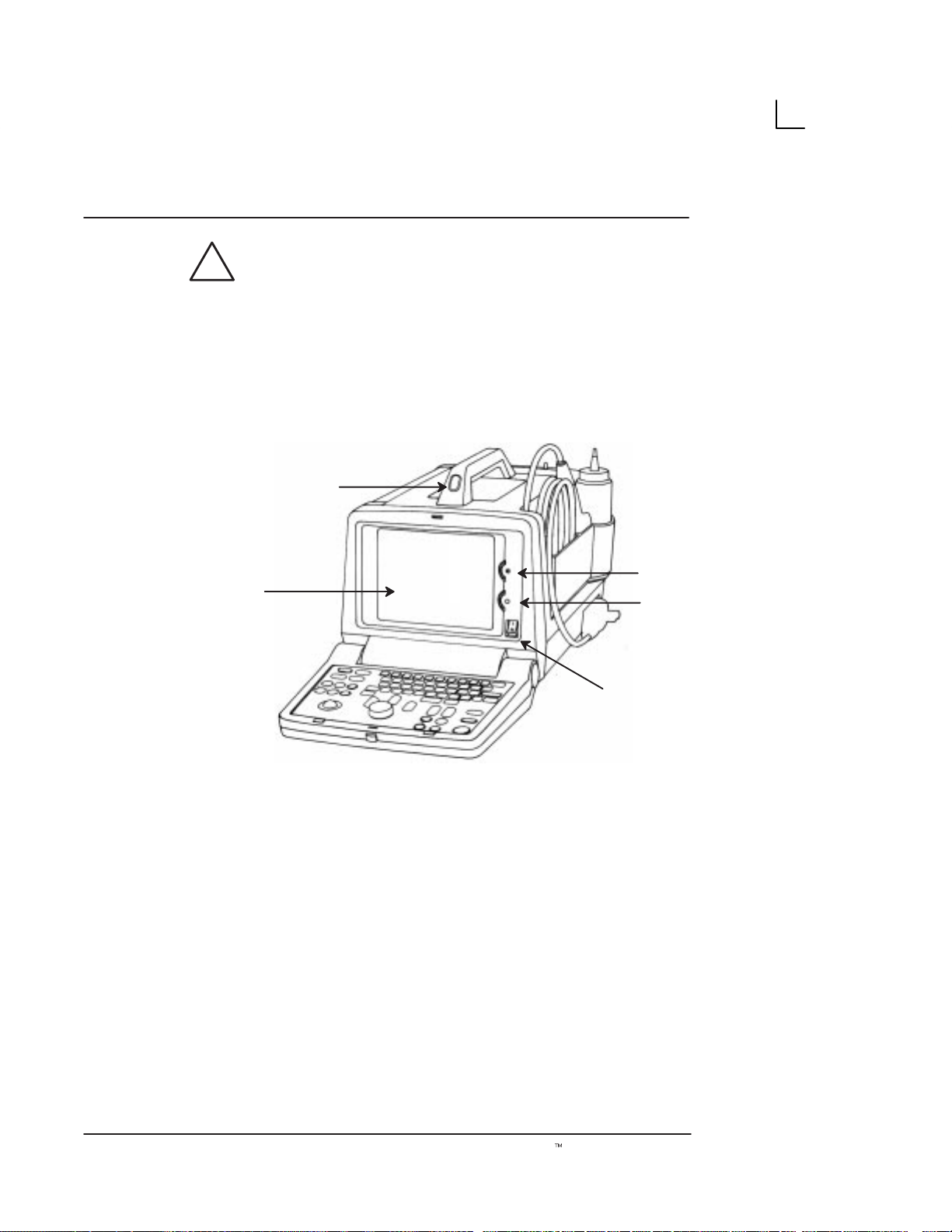
System Description
Front View
4
5
1
2
3
Illustration 1. Front View
1. Brightness: This control adjusts the brightness of
the display to the operator’s preference.
2. Contrast: This control adjusts the contrast of the
display to the operator’s preference.
3. Power ON (I)/OFF (O): Use to turn On/Off the
main AC power to the system.
4. 7–inch Monochrome Black and White Display
Monitor: It displays the image and scan
parameter data.
5. Handle: Use to aid in the movement of the system.
8
LOGIQt α100 User Manual
2211 157–100 Rev 0
Page 25
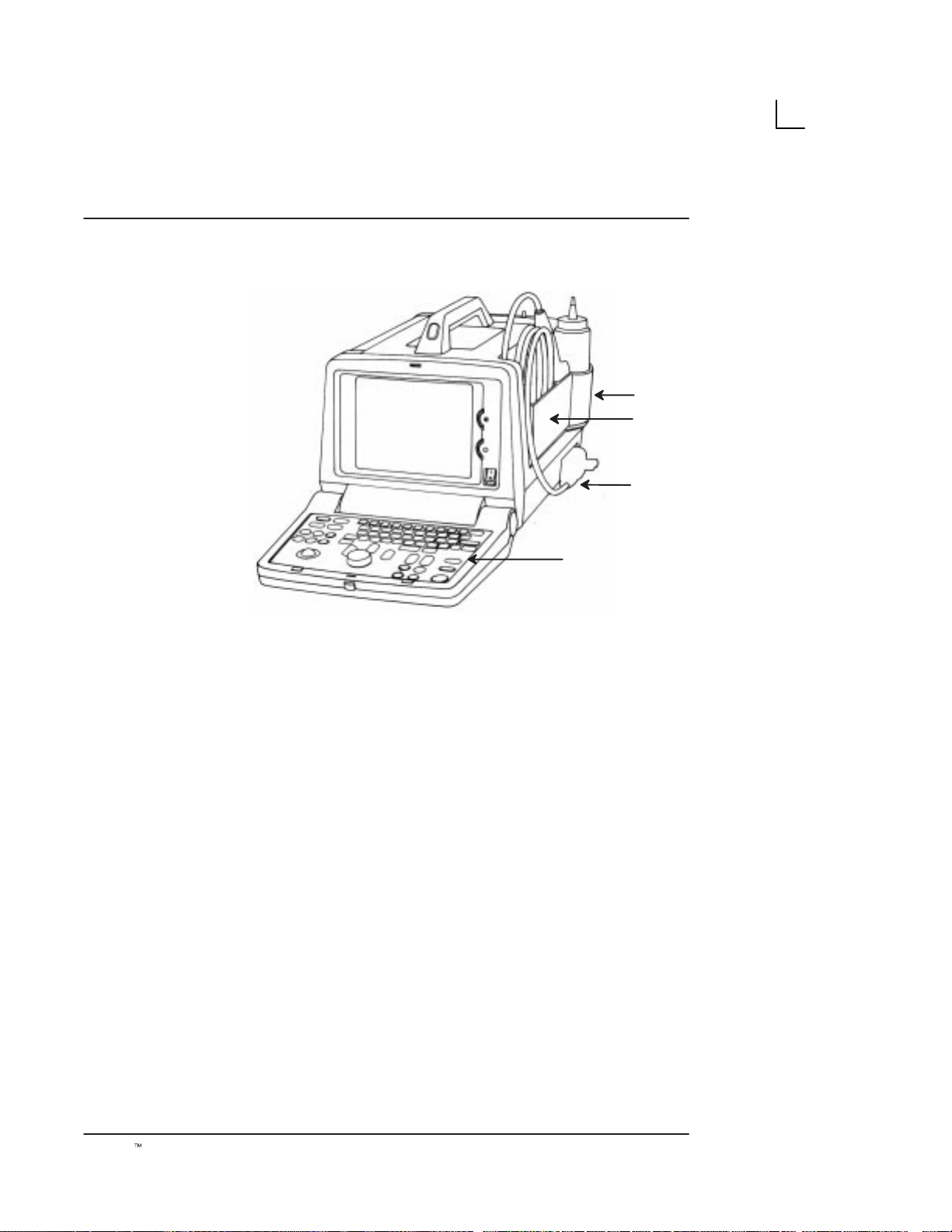
Side View
System Specifications
4
1
3
2
Illustration 2. Side View
1. Probe Holder: The probe can be stored in the
probe holder, when not in use.
2. Keyboard: Use for patient data entry, to change
scan parameters, for image annotation, VCR
controls and selection of various function menus.
3. Probe Connector: Connects the probe to the
system.
4. Gel Holder: Use to hold gel bottle when the
LOGIQ α100 is being moved.
LOGIQt α100 User Manual
2211 157–100 Rev 0
9
Page 26
System Specifications
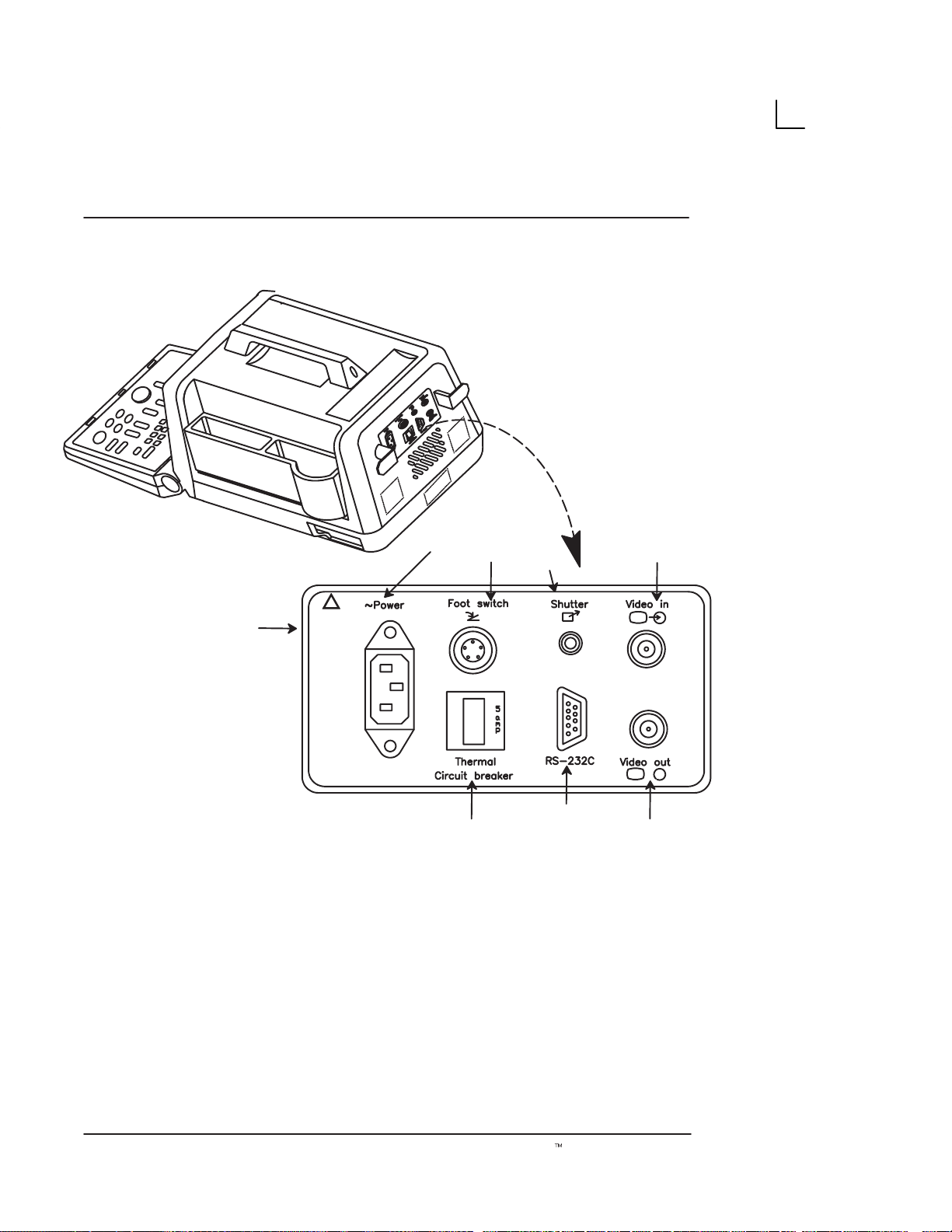
Rear View
(country specific)
[5]
!
220–240V
0.9A Max
[6]
Illustration 3. Rear View
[3]
[4]
[7]
[1]
→
[2]
1. Video IN: Enables an external video signal (VCR
playback).
2. Video OUT : Enables the connection of a video
signal to external equipment (Videographic
Printer, VCR Recording)
10
3. Foot Switch Connection: An optional Foot
Switch is provided as an accessory to be used in
parallel with or as an alternative to the Freeze
key. Enables the foot switch to freeze a real-time
image.
LOGIQt α100 User Manual
2211 157–100 Rev 0
Page 27
Rear View (cont’d)
System Specifications
4. Shutter: Connects the Video Graphic Printer for
remote operation.
5. Power Socket: Connects the main AC input.
6. Circuit Breaker: The Circuit Breaker
automatically shuts off power to the system in
case of power overload.
7. RS–232C: Used for Line Printer Interface (Serial
Port only).
.
CAUTION
NOTE: RS–232C Port shall be used with GE supplied
cable only.
Refer SV Manual 2139768 Section System Configuration
for RS–232C Pin out and, Section Renewal parts for the
Part number of the cable to be used.
Each outer (case) ground line of peripheral/accessory
connectors are Earth Grounded. Signal ground lines are
NOT Isolated.
Use only approved probes, peripherals or accessories.
Please refer to the Service Manual (2139768) for more
information about Peripherals/Accessories and their
connections.
LOGIQt α100 User Manual
2211 157–100 Rev 0
11
Page 28

System Specifications
Peripherals/Accessories
Optional Accessories
Foot Switch Connection
The foot switch, which is the remote
connected to the rear panel of the system. This extra
FREEZE
freeze image.
Two Probe Port
The two probe port module is an option that serves as an
interface to attach two probes to the single probe port of
the LOGIQ α100. It enables users to change between
probes by the press of a switch.
Trolley
The trolley is an option that serves as cart to move the
LOGIQ α100 unit within a hospital. While performing a
scan it offers ergonomical positions for monitor, probe
holder, gel holder and Video Graphic Printer.
switch is provided to enhance flexibility to
FREEZE
device, is
Video Graphic Printer
Connect the Video Graphic printer (Sony
UP–890MD/890CE) to the Video OUT provided in the
rear panel of the system. Also establish shutter
connection if required.
Video Cassette Recorder
Mount the VCR (Sony SVO–9500MD) to the Video OUT
socket provided in the rear panel for recording. For
playback, connect the VCR to the Video IN socket.
CAUTION
Use only approved probes, peripherals or accessories.
Please refer to the Service Manual (2139768) for more
information about Peripherals/Accessories and their
connections.
12
LOGIQt α100 User Manual
2211 157–100 Rev 0
Page 29

Getting Started
Preparing the System for Use
Operator Controls
System Setup
Relocating the System
This section provides more details on how features of the system are used to
prepare for scanning. It briefly explains each operator control on the keyboard
and monitor.
LOGIQt α100 User Manual
2211 157–100 Rev 0
13
Page 30

Getting Started
This page left blank intentionally.
14
LOGIQt α100 User Manual
2211 157–100 Rev 0
Page 31

Overview
Preparing the System for Use
.
Only qualified physicians or sonographers should
perform ultrasound scanning on human subjects for
medical diagnostic reasons. Request training, if needed.
Perform regular preventive maintenance. It is
recommended that service is performed by the
manufacturer or authorized service representatives only.
Never place liquids on the unit to avoid dripping into the
control panel or the unit.
Ensure that unauthorized personnel do not tamper with
the unit.
Local Site Requirements
In order to properly install the system, certain hardware
must be in place and operational within the room where
the console is used.
Before the system arrives
Ensure that the following is provided for the new system:
S
LOGIQt α100 User Manual
2211 157–100 Rev 0
A separate power outlet with a 5 amp circuit breaker
for 120 VAC (USA) or 5 amp circuit breaker for
220–240 VAC (Europe, Latin America).
15
Page 32

Preparing the System for Use
Before the system arrives (cont’d)
S
Take precautions to ensure that the system is
protected from electromagnetic interference.
Precautions include:
S
Operate the system at least 15 feet away from
motors, typewriters, elevators, and other
sources of strong electromagnetic radiation.
S
Operation in an enclosed area (wood, plaster
or concrete walls, floors and ceilings) help
prevent electromagnetic interference.
S
Special shielding may be required if the
console is to be operated in the vicinity of
Radio broadcast equipment.
.
This medical equipment is approved, in terms of the
prevention of radio wave interference, to be used in
hospitals, clinics and other institutions which are
environmentally qualified. The use of this equipment in
an inappropriate environment may cause electronic
interference. Refer to the
(2139768) and this manual for details. This equipment
can be used in residential areas only under the
supervision of physicians or qualified sonographers.
LOGIQ α100
Service Manual
Environmental Requirements
For proper functioning of the LOGIQ α100 system, care
must be taken when it is transported or stored.
Operational Storage Transport
Temperature 10_ to 40_C
50_to 104_F
Humidity 30 to 75%
non–condensing
Pressure 700 to 1060hPa 700 to 1060hPa 700 to 1060hPa
Table 1. Environmental Requirements
–10 to 60_C
14_ to 140_F
30 to 90%
non–condensing
–40_ to 60_C
–40_ to 140_F
30 to 90%
non–condensing
16
LOGIQt α100 User Manual
2211 157–100 Rev 0
Page 33

Preparing the System for Use
Environmental Requirements (cont’d)
System Acclimatization Time
After being transported, the system may be cold or hot.
In these circumstances, allow the unit to acclimatize
before turning on. It requires one hour for each 2.5
increment in temperature if the temperature is below
10_C or above 40_C.
_
C 60 55 50 45 40 35 30 25 20 15 10
_
F 140 131 122 113 104 95 86 77 68 59 50
hours 8 6 4 2 0 0 0 0 0 0 0
_
C 5 0 –5 –10 –15 –20 –25 –30 –35 –40
_
F 41 32 23 14 5 –4 –13 –22 –31 –40
hours 2 4 6 8 10 12 14 16 18 20
Table 2. System Acclimatization Time
_
Connecting and Using the System
Keyboard Preparation
Unlock the keyboard by pressing the lever on the front
panel.
Power Cord
Adhere to the electrical power rating. The system is
adaptable to 100/120 Volts or 220/240 Volts. Plug the
system power plug into the AC outlet which is located in
the rear panel.
LOGIQt α100 User Manual
2211 157–100 Rev 0
17
Page 34

Preparing the System for Use
Power Cord (cont’d)
To connect the system to the power supply:
1. Ensure that the wall outlet is of the appropriate
type.
2. Make sure that the power switch is turned off.
3. Unwrap the Power Cord. Ensure sufficient slack
in the cable so that the plug is not pulled out of
the wall if the system is moved slightly.
4. Push the power plug securely into the wall.
W ARNING
Plug
115 VAC, 140 VA
Plug and Outlet Configuration
(USA)
To avoid risk of fire, the system power must be supplied
from a separate properly rated outlet.
The system is supplied with a power cord. Under no
circumstances should this cord be altered or changed.
To assure grounding reliability, connect a ‘hospital grade’
or ‘hospital only’ grounded power outlet.
Outlet
220 VAC, 170VA
Plug and Outlet Configuration
(Europe)
18
Illustration 4. Example Plug and Outlet Configurations
LOGIQt α100 User Manual
2211 157–100 Rev 0
Page 35

Circuit Breaker
5
Preparing the System for Use
The Circuit Breaker is located on the rear panel of the
console. If the Circuit Breaker is ON power is provided to
the system, if it is OFF it removes power to the system. It
automatically shuts OFF power to the system if a power
overload occurs.
If a power overload occurs:
1. Switch OFF all peripherals.
2. Switch OFF the main power switch to the console.
3. Reactivate the Circuit Breaker switch.
The Circuit Breaker switch should stay in the ON
position. If the Circuit Breaker does not remain in the ON
position (or trips again):
1. Disconnect the power cord.
2. Call Service immediately.
DO NOT attempt to use the system.
Foot Switch Connection (Optional)
The foot switch, which is the remote
connected to the rear panel of the system. This optional
foot switch may be used in parallel with or as an
alternative to the
freeze an image. Use only the GE recommended foot
switch.
FREEZE
FREEZE
key to enhance flexibility to
device, is
LOGIQt α100 User Manual
2211 157–100 Rev 0
19
Page 36

Preparing the System for Use
Power ON/OFF
Power ON Process
The POWER ON/OFF switch is located on the front
panel. To turn the power ON, press the “I” (ON) position
on the power switch,
panel must also be in the ‘ON’ position
happens:
the Circuit Breaker on the rear
. The following
20
Illustration 5. Power On/Off
1. The system is initialized during this time:
S
A beep is heard.
S
The two LED’s,
VIDEO
S
System diagnostics run. Its status is reflected
on the monitor.
, blink and go off.
FREEZE
and
EXTERNAL
LOGIQt α100 User Manual
2211 157–100 Rev 0
ON
OFF
Page 37

Power ON Process (cont’d)
If an error occurs, an error message appears on the
screen. Refer to page 311 for more information.
Preparing the System for Use
Ver 4.0
Illustration 6. Power Up Graphic
S
Probes are initialized for immediate operation.
S
After a few seconds the B-Mode display
appears and other preset parameters like the
Dynamic Range, Gain, Depth, Near and Far
Gain, Scale, Map, Frame Averaging and
Image Inverse and Image Reverse will take
effect.
Power Off Process
LOGIQt α100 User Manual
2211 157–100 Rev 0
To turn the power OFF, press the “O” (OFF) position on
the power switch. (Refer to Illustration 5.)
1. Do not pull the power cable or turn off the circuit
breaker.
2. Store the probe in the probe holder at the side of
the system. Clean or sanitize the probe as
necessary (Refer page 263).
3. If daily maintenance is to be performed, turn off
the circuit breaker on the rear panel.
21
Page 38

Preparing the System for Use
Probe Connection
Use only approved probes. Probes can be connected or
disconnected from the system at any time regardless of
whether the system is powered ON or OFF.
Connecting a probe
1. Carefully unwrap the probe cord.
2. Do not allow the probe head to hang free. Impact
to the probe head could result in irreparable
damage.
3. Ensure probe ‘connector lock’ lever points
towards the 12 o’clock position. (See
Illustration 7.)
4. Align the connector with the probe port and
carefully push into place.
5. Turn the ‘connector lock’ to the 3 o,clock position
to secure the probe connector.
.
6. Carefully position the probe cord so that it is free
to move and is not resting on the floor.
When a probe is connected, the system will automatically
initialize the probe.
Until the Probe is connected to the system, a ‘?’ will
appear at the left top corner of the screen.
22
LOGIQt α100 User Manual
2211 157–100 Rev 0
Page 39

Disconnecting a probe
Preparing the System for Use
1. Move the probe connector lock towards the 12
o’clock position.
2. Pull the probe connector straight out of the probe
port.
3. Carefully slide the probe connector away from the
probe port.
4. Ensure the cable is free.
5. Be sure that the probe head is clean before
placing the probe into the probe holder at the side
of the system.
Illustration 7. Probe Connection/Disconnection
Probe Storage
LOGIQt α100 User Manual
2211 157–100 Rev 0
It is recommended that all probes be stored carefully.
Store the probe in the probe holder at the side of the
system when the system is being transported or put the
probe into the probe box. Additional probes should be
stored in their original shipping carton.
23
Page 40

Preparing the System for Use
Adjustment of Monitor Contrast and Brightness
Adjustment of monitor CONTRAST and BRIGHTNESS is
one of the most important factors for proper image
quality and it should be adjusted according to the lighting
in the room. If these controls are set incorrectly, the Gain
and Dynamic Range may have to be changed more often
than necessary to give the required image quality.
1. Turn the
CONTRAST
Rotary Pot, which is
positioned on the inclined face of the front panel,
clockwise or counterclockwise to get a sharp
image and a complete range of gray shades. The
lowest level of black should just disappear into
the background and the highest white should be
bright but not saturated.
2. Similarly, turn the
BRIGHTNESS
Rotary Pot,
which is positioned above the Contrast Rotary
Pot, clockwise or counterclockwise to increase
the brightness until the background is just one
shade above black.
Brightness
24
Contrast
Illustration 8. Brightness/Contrast Adjustments
LOGIQt α100 User Manual
2211 157–100 Rev 0
Page 41

Preparing the System for Use
Connection of Peripherals and Accessories
LOGIQ α100 peripherals and accessories can be
properly connected using the rear panel. Refer to
page 12 for more details.
Located on the rear panel are VIDEO IN/OUT
connections which can connect the Video Graphic Printer
or VCR. Those connections are:
S
the foot switch connection for the optional foot switch
S
the power connector for the power cord
S
the shutter which connects the Video Graphic Printer
for remote operation.
S
RS–232C for printer interface (Serial port only).
.
NOTE: RS–232C Port shall be used with GE supplied
cable only.
Refer SV Manual 2139768 Section System Configuration
for RS–232C Pin out and, Section Renewal parts for the
Part number of the cable to be used.
!
220–240V
0.9A Max
(country
specific)
→
LOGIQt α100 User Manual
2211 157–100 Rev 0
Illustration 9. Rear Panel
25
Page 42

Preparing the System for Use
This page left blank intentionally.
26
LOGIQt α100 User Manual
2211 157–100 Rev 0
Page 43

Keyboard Controls
Keyboard Layout
The keyboard is used for functions like data entry, image
optimization, annotation and measurements/calculations.
Operator Controls
Illustration 10. Keyboard Control Layout
LOGIQt α100 User Manual
2211 157–100 Rev 0
27
Page 44

Operator Controls
Key Description
New Patient
ID/Name
Press
study. Pressing the
system for the new patient entry menu. Press
abort the new patient data entry if required. Pressing
NEW PATIENT
data, annotations, measurements, calculations and
summary report pages from the system’s memory and
accepts the new entry and exits the menu.
Press
changing the current status of the system. Pressing the
ID/NAME
Patient ID/Name using alphanumeric keys. Press
CLEAR
ID/NAME
and display ID/NAME on the image display.
NEW PATIENT
a second time clears all previous patient
ID/NAME
key enables the Patient Entry Menu. Enter
to abort the ID/Name menu if required. Press
a second time (or
at the beginning of each patient
NEW PATIENT
key prompts the
CLEAR
to enter or replace patient data without
RETURN
) to exit the menu
to
WARNING
Preset
←
Comment
Selection
To avoid patient identification errors, always verify the
identification with the patient. Make sure the correct
patient identification appears on all screens and hard
copy prints.
Press
stored for the probe connected. Parameters can be
predefined using the Control–W function.
Press
image area. Use the
RETURN
Press
currently active body pattern package. Pressing the
SELECTION
Abdomen or OB/GYN) takes you to the next Body
Pattern Package automatically.
PRESET
COMMENT
to move the cursor.
SELECTION
to select the default scan parameters
to enter comments anywhere on the
to select a body pattern from the
key at the end of each menu (either
TRACKBALL, SPACE OR
28
LOGIQt α100 User Manual
2211 157–100 Rev 0
Page 45

Key Description (continued)
Rotate
The Left and Right Body Pattern
the probe marker on the selected body pattern. When
B B
Measurement
Clear
Body Pattern is not active, use the rotate keys to select
next/previous options in the measurement menu. These
keys are also used to move between the OB Report
Page, the Measurement Averaging Page and the
Anatomical Survey Page.
Press
procedures and enable calculations. The
MEASUREMENT
MEASUREMENT
during Ellipse adjustment and distance measurements.
The
CLEAR
screen and terminates control sequences in the order in
which they are done.
Operator Controls
ROTATION
to start measurement
key also toggles the movable cursor
key clears measurements, comments, help
keys rotate
Near Far
Dyn. Range
Scroll
NEAR
the image up to 20mm depth.
overall gain in the far field of the image beyond 20mm
depth. The
activate the Ellipse Measurement function after the first
distance measurement has been set.
DYNAMIC RANGE
echoes. The echoes are converted into visual shades of
gray. Adjusting the dynamic range thus affects the range
of shades displayed. Increase dynamic range to get a
smoother image. Decrease dynamic range to achieve an
image with more contrast.
SCROLL
Left/Right, Up/Down on the Display in B–Mode. Scrolling
Up/Down in M-Mode is possible. Scrolling Left/Right in
M–Mode is not possible.
Gain controls the overall gain in the near field of
FAR
Gain controls the
NEAR
← →↑↓enables scrolling the live image
Gain controls are also used to
adjusts the intensities of returning
LOGIQt α100 User Manual
2211 157–100 Rev 0
29
Page 46

Operator Controls
Key Description (continued)
Gain/Rotate
Depth
Focus
B
M
GAIN/ROTATE
The
returning echoes in both B- and M-Modes. When the
image is frozen, this knob acts as a
for rotating the probe marker on body patterns and the
lines in Hip Dysplasia.
DEPTH
Refer page 259 for Depth details.
FOCUS
for transmit. A focus marker on the right side of the
display indicates the image area which is focussed. Two
focus markers appear in Combination Focus mode.
B MODE
when the system is turned on.
determines the depth of the image displayed.
enables the selection of the optimal focal depth
(Brightness Mode) format appears as a default
knob adjusts the amplification of the
ROTATE
knob used
L R
30
M MODE
M-Mode formats.
*
A MODE
Use CONTROL Q to toggle between B/A and B/M.
(Motion Mode) toggles between B/M- and
(Amplitude Mode) –Use M key to go to B/M.
* Applicable only for systems delivered in India.
LEFT/RIGHT
The
images. The left image appears after the Left key is
pressed. Pressing the Right key freezes the left image
while activating the right image. Press
freeze the active image.
keys are used to display dual B-Mode
FREEZE
LOGIQt α100 User Manual
2211 157–100 Rev 0
to
Page 47

Key Description (continued)
Ext. Video
j
ff
Record
Freeze
A"
EXTERNAL VIDEO
(VCR playback) to be viewed on the LOGIQ α100
system monitor. A LED lights when the key is pressed. It
is a toggle key.
RECORD
printer to print images or report pages appearing on the
display monitor.
FREEZE
data on a displayed image and freeze the image in
system memory. If pressed again, it unfreezes the image
and erases all measurements from the screen and
continues live image acquisition.
Operator Controls
enables an external video signal
is used to trigger a device like a videographic
is used to stop the acquisition of ultrasound
Return
Set
Reverse
Press
BACK SPACE
to erase individual characters to the
left of the cursor while entering alphanumeric information.
Press
RETURN
to go to the next line of annotation. It can
also be used to go from one field to the next in the
Installation Setup Menu, the European OB Table Setup
Menu, OB Report Pages and the New Patient, ID/Name
Menu.
Press
Press
SET
to start or finish an operation.
REVERSE
key to reverse the image from Left to
Right. Press a second time to reverse the image from
Right to Left.
Press SHIFT +
REVERSE
to invert the image from Top to
Bottom. Press a second time to invert the image from
Bottom to Top.
LOGIQt α100 User Manual
2211 157–100 Rev 0
31
Page 48

Operator Controls
Key Description (continued)
Ctrl
Enter
CONTROL/ENTER
alphanumeric keys to activate all control functions. Refer
Chapter Control Keys on page 237 for more details.
When
used to execute an operation. It is also used in the
following contexts:
D
D
Installation Setup Menu and the European OB Table
Setup Menu.
SPACE
or words.
CONTROL/ENTER
to come out of report pages and OB User Table Editor
to go from one field to the next in the
is used to enter a distance between 2 characters
TRACKBALL
functions.
function key pressed.
TRACKBALL
is used along with certain
is pressed a second time, it is
is used with Measurement and Annotation
control depends on the last
32
Hints
If an error is detected that limits operation, press
to clear the operation.
LOGIQt α100 User Manual
2211 157–100 Rev 0
CLEAR
Page 49

Setup Procedure
After connecting the system, set up the system by following the procedure
listed below:
Ctrl
Enter
S
1
Ctrl
Enter
System Setup
Press
an Installation Setup window appears. When this function
is enabled, the image, measurements, body patterns and
comments (if any) are temporarily removed from the
screen.
Illustration 11 Installation Setup Menu
CTRL–S1 ENTER
for the Installation Setup menu,
1. HOSPITAL NAME:
2. DATE FORMAT: 1
1:DD/MM/YY 2:MM/DD/YY 3:YY/MM/DD)
3. DATE: 4.TIME:
5.OB VERSION SELECTED: 1
(1:US 2:TOKYO 3:OSAKA 4:EUROPE 5:ASUM)
6.FILM EXPOSURE TIME: 4
(1:125ms 2:250ms 3:375ms 4:500ms)
7.MINIMUM FILM EXPOSURE INTERVAL : 2 (1–9 seconds)
8.VIDEO INVERT FOR REPORT PRINT : 2 (1:YES2:NO)
9.CIRCUMFERENCE MEASUREMENT METHOD: 1
(1:ELLIPSE 2:2DISTANCE 3:TRACE)
10. US GA SELECTION : 1(1:CUA 2:AUA)
11. ADD 1 WEEK TO EDD : 1 (1:NO 2:YES)
12. LANGUAGE : 1 (1:ENG 2:GER 3:FRE 4:ITA 5:POR 6:SPA)
13. HIP ORIENTATION:1 (1.CRANIAL LEFT 2.CAUDAL LEFT)
LOGIQt α100 User Manual
2211 157–100 Rev 0
INSTALLATION SETUP
XX/XX/XX
XX:XX
33
Page 50

System Setup
Setup Procedure (cont’d)
Use the
RETURN
the fields. Use
left of the cursor.
Press
display. Pressing any other key would result in a beep,
indicating it is an error.
Press
registering any inputs.
TRACKBALL, SHIFT
keys to move from up/down, or left/right to edit
BACK SPACE
SET
to register the inputs and return to the original
CLEAR
to return to the original display without
↑↓← →,
to delete a character to the
CTRL/ENTER
or
34
LOGIQt α100 User Manual
2211 157–100 Rev 0
Page 51

Moving the system
When moving or transporting the system, follow the
precautions below to ensure maximum safety of
personnel, system and other equipments.
Relocating the System
1. Switch OFF power to the system.
2. All cables connecting the peripherals (Video
Graphic Printer, etc.) should be disconnected
from the system.
3. Ensure that no loose items are left on the
console.
4. Lock the keyboard onto the front panel.
5. Wrap the system’s power cord securely onto the
hooks on the rear side of the system.
6. Put the probe into the probe holder or the probe
box provided with the probes.
CAUTION
LOGIQt α100 User Manual
2211 157–100 Rev 0
7. Put the gel bottle into the gel holder at the side of
the system.
8. Carry the equipment by grasping the handle on
top of the system.
9. When using the Two Probe Port Option do not
carry the system with the probes connected to the
Two Probe Port. This will avoid damage to the
probe connectors. Always carry the equipment
with the Two Probe Port facing away from your
body.
Do not apply any pressure on the system. Make sure the
handle is free from any oil, gel or any slippery substance
which may cause the system to drop.
35
Page 52

Relocating the System
Transporting the system
Use extra care when transporting the system using
vehicles. Follow precautions below:
1. Keep the unit upright.
2. Prevent vibration damage by driving cautiously.
Avoid unpaved roads, excessive speeds and
sudden stops and starts.
36
LOGIQt α100 User Manual
2211 157–100 Rev 0
Page 53

Safety
Precaution Levels
Hazard Symbols
Patient Safety
Equipment and Personnel Safety
Device Labels
Warning Labels/Locations
This section is important in order to become familiar with precaution levels and
hazard symbols used in this manual and on the system. It explains patient,
system and personnel safety concerns. The controls that affect acoustic output
levels are shown in table form.
LOGIQt α100 User Manual
2211 157–100 Rev 0
37
Page 54

Safety
This page left blank intentionally.
38
LOGIQt α100 User Manual
2211 157–100 Rev 0
Page 55

Overview
Icon Description
Precaution Levels
This section is important in order to become familiar with
precaution levels and hazard symbols used in this
manual and on the system. It explains patient, system
and personnel safety concerns. The controls that affect
acoustic output levels are shown in the form of a table.
Before using the machine, study the manual. Carefully
review the manual periodically for warnings, safety
precautions and maintenance requirements to avoid
conditions that could result in injury.
Precautionary statements and warning labels are
provided in various locations on the LOGIQ α100
console and throughout this manual to alert the user to
hazards or situations that could result in injury or
equipment damage. Symbols are often used with these
warnings to increase user awareness and emphasize
particular hazards. The user should become familiar with
the meaning of symbols and the intent of all product
warnings and precautionary statements.
DANGER
LOGIQt α100 User Manual
2211 157–100 Rev 0
Indicates that a specific hazard is known to exist which
through inappropriate conditions or actions will cause:
S
S
Severe or fatal personal injury.
Substantial property damage.
39
Page 56

Precaution Levels
Icon Description (cont’d)
WARNING
CAUTION
.
.
FOR USA
ONLY
Indicates that a specific hazard is known to exist which
through inappropriate conditions or actions may cause:
S
Severe personal injury.
S
Substantial property damage.
Indicates that a potential hazard may exist which through
inappropriate conditions or actions will or can cause:
S
Minor injury.
S
Property damage.
Indicates precautions or prudent use recommendations
that should be used in the operation of the ultrasound
system, specifically:
S
Use of the ultrasound system as a prescription device
under the order of the physician.
S
Noting or emphasizing a necessary operator
action.
S
Maintaining an optimum system environment.
S
Step or time saving recommendations.
40
LOGIQt α100 User Manual
2211 157–100 Rev 0
Page 57

Icon Description
Icon
Biological
Hazard
Electrical
Hazard
Acoustic
Output
Hazard
Explosion
Hazard
Hazard Symbols
Potential hazards are indicated by the following icons:
Potential
Hazard
S
Patient/user
infection due to
contaminated
equipment.
S
Electrical microshock to
patient, e.g.,
ventricular
fibrillation
initiated.
S
Electrical
macroshock to
patient/
user.
S
Patient injury or
tissue damage
from ultrasound
radiation.
S
Risk of
explosion if
used in the
presence of
flammable
anesthetics.
Usage Source
S
Cleaning and
care
instructions
S
Sheath and
glove guidelines
S
Probes
S
ECG
S
Connections to
rear panel
S
ALARA, the use
of acoustic
output following
the as low as
reasonably
achievable
principle
S
Keep away form
flammable
anesthetic
ISO 7000
No. 0659
LOGIQt α100 User Manual
2211 157–100 Rev 0
Table 3. Potential Hazards
41
Page 58

Hazard Symbols
Icon Description (cont’d)
Icon
S
Smoke
& Fire
Hazard
Non–
Ionizing
Radiation
Table 3. Potential Hazards (cont’d)
Patient/user
injury or
adverse
reaction from
fire or smoke.
S
Patient/user
injury from
explosion and
fire.
S
Console
failure, erratic
operation or
output error
due to RF
interference.
Potential
Hazard
Usage Source
S
Replacing
fuses
S
Outlet
guidelines
S
RF IEC 878
No. 03-04
Important Safety Considerations
The following sections (
and Personnel Safety
equipment user aware of particular hazards associated
with the use of this equipment and the extent to which
injury can occur if precautions are not observed.
Additional precautions may be provided throughout the
manual. The equipment user is obligated to be familiar
with these concerns and avoid conditions that could
result in injury.
Patient Safety
, and
Equipment
) are intended to make the
42
LOGIQt α100 User Manual
2211 157–100 Rev 0
Page 59

Related Hazards
Patient Safety
The concerns listed below can seriously affect the safety
of patients undergoing a diagnostic ultrasound
examination.
Patient
Identification
Diagnostic
Information
Clinical Diagnosis
Patient ID/Name should be entered accurately. Make
sure correct patient ID is provided on all recorded data
and hard copy prints. Identification errors could result in
an incorrect diagnosis.
Equipment malfunction or incorrect settings can result in
measurement errors or failure to detect details within the
image. The equipment user must become thoroughly
familiar with the equipment operation in order to optimize
its performance and recognize possible malfunctions.
Applications training is available through your local GE
representative. Added confidence in your equipment
operation can be gained by establishing a quality
assurance program.
Only qualified physicians and sonographers should
perform Ultrasound scanning on human subjects for
medical diagnostic reasons. Exposure levels to be kept
to minimum and to be consistent with recommended
practices for diagnostic evaluation.
Calculation formulas and data base are provided only as
a tool and should not be the basis in which clinical
diagnosis can be made. The user is encouraged to
research the articles and sample the output data from
this device and make a judgement as to the utility of this
and calculation results as a clinical tool.
LOGIQt α100 User Manual
2211 157–100 Rev 0
43
Page 60

Patient Safety
Related Hazards (cont’d)
Mechanical
Hazards
Electrical
Hazard
Damaged probes or improper use and manipulation of
intracavitary probes can result in injury or increased risk
of infection. Handle the probes with care. They may be
damaged if dropped or mishandled. A damaged probe
has to be scrapped. It cannot be repaired or reused. Do
not allow the lens to come into contact with a sharp
object or to be knocked against an object. Be sure to put
the transducers in the side slot before transporting.
A damaged probe may cause an electrically hazardous
condition if conductive solutions come in contact with
internal live parts. Do not use any probe with damaged
lens to scan a patient. Inspect probes often for cracks or
openings which could allow liquid entry.
To avoid electrical shock, use only the supplied power
cords and connect them only to properly grounded (three
hole) wall outlets. Do not use a 2 prong–adaptor.
The system should be operated within the voltage limits
defined in
Do not place liquids on or above the console. If the
liquid spills, it may come in contact with live parts and
increase the risk of shock.
Standard Specifications
on page 5.
44
This system contains no operator serviceable
components. Do not remove the system covers. Only
qualified Service personnel should service the system.
Accidentally contacting the electrical circuits inside the
housing could cause serious injury. Do not use with
defibrillators.
LOGIQt α100 User Manual
2211 157–100 Rev 0
Page 61

Related Hazards (cont’d)
Patient Safety
Acoustic
Output
Hazard
Although there have been no confirmed adverse effects
produced by diagnostic levels of ultrasound, avoid
unnecessary exposure of ultrasound energy to the
human body. Wrong scan settings, probe positioning and
tissue type can result in injury. Use the minimum
necessary output to get the best diagnostic image or
measurement during an examination. Begin an exam
with a probe that provides optimum focal depth and
penetration.
Follow the principle of “as low as reasonably achievable”
(ALARA) when scanning patients. Once an optimal
image is achieved, the need for prolonging the exposure
cannot be justified.
The principle of ALARA, which stands for “As Low As
Reasonably Achievable”, is to keep the radiation
exposure at the minimum level necessary to obtain the
diagnostic information. This principle is widely practiced
in medical X–ray protection where exposure at any level
is potentially harmful. Historically, ALARA was initiated as
a cautious approach for dealing with uncertain hazards
but has since become the principle method for reducing
the risk of injury from hazards that do not have safe
minimum thresholds.
While no minimum thresholds for harmful bio-effects
have been established with the use of diagnostic
ultrasound, the principle of ALARA can be readily
implemented on equipment incorporating an output
display. As the operator adjusts the equipment to
optimize the image quality, the display interactively
updates to indicate the effect on output.
LOGIQt α100 User Manual
2211 157–100 Rev 0
45
Page 62

Patient Safety
This page left blank intentionally.
46
LOGIQt α100 User Manual
2211 157–100 Rev 0
Page 63

Equipment and Personnel Safety
Related Hazards
The concerns listed below can seriously affect the safety
of the equipment and personnel during a diagnostic
ultrasound examination.
Explosion
WARNING
Electrical
Hazard
Hazard
Smoke
& Fire
Hazard
Do not operate the system in the presence of flammable
anesthetics. The system is not designed for such use,
since it can lead to an explosion.
This equipment contains dangerous voltages that can
cause serious injury or death.
To avoid injury:
S
Do not remove protective covers. No user serviceable
parts inside. Refer servicing to qualified service
personnel.
S
To assure adequate grounding, connect the power
plug to a reliable (hospital grade) grounding outlet
(having a equalization conductor
S
Do not place liquids on or above the console. Spilled
liquid may contact live parts and increase the risk of
shock.
The system must be supplied from an adequately rated
power outlet. The capacity of the power outlet must be as
specified in the LOGIQ α100 Service Manual
(2139768).
).
LOGIQt α100 User Manual
2211 157–100 Rev 0
47
Page 64

Equipment and Personnel Safety
Related Hazards (cont’d)
Biological
.
CAUTION
FOR USA
ONLY
Hazard
For patient and personnel safety beware of biological
hazards while performing invasive procedures. To avoid
the risk of disease transmission:
S
Use protective barriers like FDA cleared gloves and
probe sheaths. Follow sterile procedures when
appropriate.
S
Thoroughly clean probes and reusable accessories
after each patient examination and disinfect or
sterilize as needed. Refer to page 263 for details.
S
Follow all infection control policies established by
your office, department or institution as they apply to
personnel and equipment.
Caution: United States law restricts the device to
sale or use by or on the order of the physician.
Devices containing latex may cause severe allergic
reaction in latex sensitive individuals. USA customers
should refer to the FDA’s March 29, 1991 Medical Alert
on latex products.
48
LOGIQt α100 User Manual
2211 157–100 Rev0
Page 65

Device Labels
Label Icon Description
The following table describes the purpose and location of
safety labels and other important information provided on
the equipment.
Label Publication Description Location
IEC 417–5032
IEC 417–5019
IEC 417–5036
IEC 417–5007
IEC 417–5008 OFF (Power: disconnection
IEC 417–5056 Brightness
IEC 417–5057
Alternating Current Single
Phase
Protective earth
(grounding)
Warning, High Voltage
ON (Power: connection
to the Mains)
from the Mains)
Contrast
Rear Panel
Internal
On the CRT,
on the fly back
transformer
Front Panel
Front Panel
Front Panel
Front Panel
IEC 878–01–36 Video Input
IEC 878–01–37
LOGIQt α100 User Manual
2211 157–100 Rev 0
Video Output
Table 4. Device Labels (Part 1)
Rear Panel
Rear Panel
49
Page 66

Device Labels
Label Icon Description (cont’d)
Label/Symbol Description Location
Identification and
Rating Plate
Type/Class Label
Device Listing/
Certification Labels
“DANGER – Possible
explosion hazard, if
used in the presence
of flammable
anesthetics.”
!
Manufacturer’s name and address
Date of Manufacture
Model and Serial numbers
Electrical ratings
Used to indicate the degree of safety or
protection
Laboratory logo or labels denoting
conformance with industry safety
standards such as UL or IEC
This system is not designed for use with
flammable anesthetic gases
“ATTENTION – Consult accompanying
documents” is intended to alert the user
to refer to the operator manual or other
instructions when complete information
cannot be provided on the label.
Type BF Equipment (man in the box
symbol) IEC 878–02–03 indicates
B Type equipment having a floating
applied part.
Rear of
Console
Rear of
Console
Rear of
Console
External
Rear of
Console
External
IP Code
(IPX1)
50
“CAUTION” The equilateral triangle is
usually used in combination with other
symbols to advise or warn the user.
Indicates degree of protection provided
by the enclosure for IEC 529. IPX1 indicates drip proof.
Table 5. Device Labels (Part 2)
LOGIQt α100 User Manual
Rear of
Console
Foot Switch
2211 157–100 Rev 0
Page 67

Device Labels
Classifications
Type of protection against electric shock: Class I EQUIPMENT *1
*1. Class I EQUIPMENT
EQUIPMENT in which protection against electric shock does not
rely on BASIC INSULATION only, but which includes an additional
safety precaution in that means are provided for the connection of
the EQUIPMENT to the protective earth conductor in the fixed wiring
of the installation in such a way that ACCESSIBLE METAL PARTS
cannot become LIVE in the event of a failure of the BASIC
INSULATION.
Degree of protection against electric shock: Type BF EQUIPMENT *2
*2. Type BF EQUIPMENT
Type B EQUIPMENT with a F–TYPE isolated applied part providing
a degree of protection against electric shock to such a degree that
the allowable PATIENT LEAKAGE CURRENT under SINGLE
FAULT CONDITIONS is not exceeded when 1.1 times the highest
rated MAINS VOLTAGE is applied between the APPLIED PART and
earth.
EMC – Electromagnetic Compatibility
EMC Performance
All types of electronic equipment may characteristically cause
electromagnetic interference with other equipment, either transmitted
through air or connecting cables. The term EMC indicates the capability
of the equipment to curb electromagnetic influence from other
equipment and at the same time not affect other equipment with similar
electromagnetic radiation from itself.
This product is designed to fully comply with the EN60601–1–2
(IEC601–1–2), Class A, in medical electric equipment EMC regulations.
Proper installation following the service manual is required in order to
achieve the full EMC performance of the product.
In case of issues related to EMC, please call your service personnel.
LOGIQt α100 User Manual
2211 157–100 Rev 0
51
Page 68

Device Labels
EMC – Electromagnetic Compatibility (cont’d)
Notice upon Installation of Product
1. Use either power supply cords provided by GE Medical Systems
or ones designated by GE Medical Systems. Products equipped
with a power source plug should be plugged into the fixed power
socket which has the protective grounding conductor. Never use
any adaptor or converter to connect with a power source plug
(i.e. three–prong–to–two prong converter).
2. Locate the equipment as far away as possible from other
electronic equipment.
3. Be sure to use only the cables provided by or designated by GE
Medical Systems. Connect these cables following the installation
procedures (i.e. wire power cables separately from signal
cables).
4. Lay out the main equipment and other peripherals following the
installation procedures described in the Service manual.
General Information
1. Designation of Peripheral Equipment Connectable to this
Product, refer page 25. These Peripherals can be hooked up to
the product without compromising its EMC performance.
2. Avoid using equipment not designated for the LOGIQ α100.
Failure to comply with this instruction may result in poor EMC
performance of the product.
3. Notice against User Modification:
Never Modify this product. Unilateral user modification may
cause degradation in EMC performance.
Modification of the product includes:
a. Changes in cables (length, material, wiring etc.)
b. Changes in system insulation/layout.
c. Changes in system configuration/components.
d. Changes in securing system parts (cover open/close).
52
LOGIQt α100 User Manual
2211 157–100 Rev 0
Page 69

EMC – Electromagnetic Compatibility (cont’d)
4. Operate the system with all covers closed. If a cover is opened
for some reason ensure to shut it before starting/resuming
operation.
Device Labels
.
CAUTION
NOTE: Operating the system with any cover open may
affect EMC performance.
Do not use the following devices near the
system. Devices which intrinsically transmit radio waves
such as cellular phone, radio transceiver, mobile radio
transmitter radio–controlled toy, etc. Use of these devices
could cause the
outside the published specifications. Keep power to
these devices turned off when near the system.
Medical staff in charge of the
required to instruct technicians, patients and other
people who may be around the system to fully comply
with the above regulation.
LOGIQ α100
system to perform
LOGIQ α100
LOGIQ α100
system is
LOGIQt α100 User Manual
2211 157–100 Rev 0
53
Page 70

Device Labels
EMC – Electromagnetic Compatibility (cont’d)
Patient Environmental Devices
Acceptable Devices
CAUTION
Unapproved Devices
CAUTION
Do not connect any probes or accessories without
approval by GE. Those listed in Page7 have been tested
and verified to be compatible with the LOGIQ α100
system.
The user takes all responsibility for connecting
unapproved devices. If devices are connected without
the approval of GE, the warranty will be INVALID.
Any devices connected to the LOGIQ α100 System must
conform to one or more of the requirements listed below:
S
IEC 50, IEC 65, IEC 335, IEC 348, IEC 414, IEC 820,
IEC 950, IEC 1010–1, ISO 7767, ISO 8185, ISO
8359 OR IEC 601–1.
S
The devices should be connected to ‘Protective
Earth’ (Ground).
54
LOGIQt α100 User Manual
2211 157–100 Rev 0
Page 71

Warning Labels
Warning Labels/Locations
Danger/Caution Label
!
DANGER
Possible explosion hazard if
used in the presence of
flammable anesthetics.
!
CAUTION
Do not use with Defibrillator.
__________________________
United State law restricts this
device to sale or use by or on the
order of a physician
Illustration 12. Warning Label Locations
LOGIQt α100 User Manual
2211 157–100 Rev 0
Warning
WARNING
!
Possible shock hazard. Do not
remove Covers or Panels. Refer
servicing to qualified personnel.
–––––––––––––––––––––––––––
For continued protection against
fire or shock hazard – Replace
only with same type and rating of
Fuse.
–––––––––––––––––––––––––––
Grounding reliability can only be
achieved with “Hospital only” or
“Hospital Grade” cordset provided
with the system
55
Page 72

Device Labels
Warning Labels (cont’d)
Regulatory Labels
Caution Label
!
CAUTION
Do not use the following devices
near this equipment.
Cellular phone, radio transceiver,
mobile radio transmitter,
radio–controller toy , etc.
Use of these devices could cause
this equipment to perform outside
the published specifications.
Keep power to these devices
turned off when near this
equipment.
56
Illustration 12. Warning Label Locations (cont’d)
LOGIQt α100 User Manual
2211 157–100 Rev 0
Page 73

Warning Labels (cont’d)
Device Labels
Rating Plate
Made for GE Medical Systems,
MODEL :
MANUFACTURED :
LOCATION : Wipro GE Medical Systems Ltd.
Bangalore, India
SERIAL :
VOLTS : VX, PHASE I
AMP LONG TERM : AMP
FREQUENCY : 50/60 Hz
CLASS I
For Europe
Illustration 12. Warning Label Locations (cont’d)
Milwaukee, Wisconsin by
Wipro GE Medical Systems Ltd.,
Bangalore, INDIA
50/60
For Asia & America
LOGIQt α100 User Manual
2211 157–100 Rev 0
57
Page 74

Device Labels
This page left blank intentionally.
58
LOGIQt α100 User Manual
2211 157–100 Rev 0
Page 75

Scan Procedures
Patient Registration
Image Display
Scan Adjustments
VCR Operations
Two Probe Port
This section describes the basic elements of the system and it displays common
types of modes of scanning.
This section is a guide to perform a scan. It includes scan adjustments required
to get optimal image display.
LOGIQt α100 User Manual
2211 157–100 Rev 0
59
Page 76

Safety
This page left blank intentionally.
60
LOGIQt α100 User Manual
2211 157–100 Rev 0
Page 77

Patient Registration
Introduction
Turn ON the System by pressing the POWER Switch to
the “I” (ON) position. The system beeps once and runs a
self test. The system defaults to B-Mode format.
Patient Registration Procedure
Begin an exam by entering new patient information.
Press the
patient study. A patient data entry menu appears on the
monitor. Enter Patient Identification (16 characters)
using alphanumeric keys, press
Patient Name field (28 characters). Enter Patient Name.
Press
and exit out of the menu
Press
required.
NEW PATIENT
RETURN
CLEAR
or
to exit
key at the beginning of each
RETURN
NEW PATIENT
or
NEW PATIENT
to go to the
to register the inputs
and abort entry if
LOGIQt α100 User Manual
2211 157–100 Rev 0
61
Page 78

Patient Registration
Patient Registration Procedure (cont’d)
NEW PATIENT
ID: (Up to 16 chars)
NAME: (Up to 28 chars)
Press “New Patient” to enter new data and exit
Press “Clear” to cancel and exit
Return
.
NOTE: To modify only Patient Information without
erasing other data, press the ID/NAME key. Pressing
ID/NAME allows modification of patient data without
erasing patient image, measurements, calculations and
summary reports.
Pressing NEW PATIENT key twice, clears all patient
data, annotations, measurements, calculations and
summary report pages from the system’s memory.
Patient Scan Procedure
1. Position the patient in a lying down position and
2. Begin the scan on the patient.
Register and exit Register and exit
Illustration 13. New Patient Entry
apply Acoustic gel to the probe and on the
patient. Position the transducer on the patient,
adjust the imaging controls to produce a high
quality image.
Abort/Exit
62
LOGIQt α100 User Manual
2211 157–100 Rev 0
Page 79

Patient Scan Procedure (cont’d)
3. A real-time image appears on the monitor through
the following controls:
S
Orient the probe on the patient based on the
study to be performed or view to be obtained.
Patient Registration
S
Increase or decrease the overall
and
FAR
gain controls and
to obtain the desired Image quality.
S
If the image is not bright, increase the overall
‘Gain’ until the appropriate brightness is
obtained. The amplitude of returning echoes
should be optimally displayed.
S
Increase
smoother image.
S
Decrease
with more contrast.
S
Position the
interest.
4. Press
start measurements.
5. Refer to the Chapter on
for details on making measurements.
6. Enter comments on the image area if required.
7. The image and the report page can be printed
using a Video Graphic Printer. Patient’s Name
and Identification Number is transferred with each
Image during hard copy printing.
FREEZE
DYNAMIC RANGE
DYNAMIC RANGE
FOCUS
to stop image acquisition and to
marker in the area of
General Measurements
GAIN, NEAR
DYNAMIC RANGE
to get a
to get an image
LOGIQt α100 User Manual
2211 157–100 Rev 0
63
Page 80

Patient Registration
This page left blank intentionally.
64
LOGIQt α100 User Manual
2211 157–100 Rev 0
Page 81

Overview
Image Display
The LOGIQ α100 system offers a variety of display
formats. Each format shows the operator valuable
information relating to patient data and system scan
parameters.
Time
Probe/
Biopsy
Zone
Gray
Scale
Body
Pattern
HOSPITAL NAME(30 CHARS)
ST. JOHNS HOSPITAL
06/01/96Date
09:24:50
C36 BX–3
GE
!
G
R
E
Y
S
C
A
L
E
G50 DR54 D150
ID:(16 CHARS)
Biopsy Line
PATIENT NAME(28 CHARS)
XXXXXXXXXXXXXXXXXXX
1234567890123456
A
d
N–0 F–0
Confirm BX type of Bracket
Calculation
Result
Area
LOGIQt α100 User Manual
2211 157–100 Rev 0
1:BPD 2:CRL 3:FL 4:AC 5:HC 6:EDD 7:EFW 8:AFI 9:HIP 0:NXT
Gain
Dynamic Range
Depth
Main Menu
Illustration 14. Monitor Display
65
Page 82

Image Display
*B/A-Mode
M
Press the M Mode key to acquire a
Press CONTROL Q to go to
image appears on the left side and the A-Mode image
appears on the right side. To exit the
CONTROL Q again and it reverts to
the
B
Mode key to return to the original display. Not
B/A
exiting the
the system to default back to
M–Mode key is pressed in B–Mode and M–Mode.
Mode by pressing CONTROL Q causes
B/A
B/M-
Mode image.
Mode. The B-Mode
B/A
Mode, press
B/M
Mode. Press
B/A
Mode when the
.
66
Illustration 15. B/A Mode Display
NOTE: When the B Mode key is pressed in B/A Mode,
the system returns to B-Mode retaining current scan
values. It erases measurements. If M Mode key is
pressed now the system goes back to B/A Mode.
When M Mode key is pressed in B/A Mode, the system
reverts to M Mode and if M Mode key is pressed again it
goes back to B/A Mode.
Only Distance Measurements are possible in B/A Mode.
A/B Ratio is the only calculation that is allowed. Invoking
Heart Rate, Velocity or Volume measurements causes
the system to beep and displays and ILG message.
Dynamic Range, Focus, Depth and Gain Control
adjustments affect the B/A-Mode image.
* Applicable only for systems delivered in India.
LOGIQt α100 User Manual
2211 157–100 Rev 0
Page 83

B-Mode
B
Image Display
B-Mode display appears by default when the system is
turned ON. While working in another mode, press the
Mode key to return to the B-Mode Display.
B
LOGIQt α100 User Manual
2211 157–100 Rev 0
Illustration 16. B-Mode Display
67
Page 84

Image Display
B-Mode (cont’d)
B-Mode Display Description
Hospital Name Shows the name of the hospital or institution. A
maximum of 30 alphanumeric characters can be
entered. Press CONTROL–S1 to display the
Installation Setup menu and input hospital name.
Patient Name A maximum of 28 characters. Press the NEW
PATIENT key or ID NAME key and input name.
ID Patient Identification Number. A maximum of 16
alphanumeric characters. Press the NEW PATIENT
key or ID NAME key and input ID.
Date Current date according to the system settings, press
CONTROL–S1 to display the Installation Setup menu
and input current date.
Select date format in the Installation Setup menu:
DD/MM/YY, MM/DD/YY or YY/MM/DD.
Time Displays the current time during normal operation.
Press CONTROL–S1 to display the Installation Setup
menu and input the current time.
Probe Probe name of the active probe.
Depth Shows the display depth.
Gray Scale Shows the B-Mode Gray Scale assignment.
Body Pattern Shows the Body Pattern selected for scan orientation.
Calculation Result Area Displays all the calculation results.
Gain Displays the overall B-Mode or M-Mode Receive Gain.
Dynamic Range Dynamic Range shows the range over which the echo
intensities are converted to gray scale. Displayed in
6 dB steps. Adjustable from 30-72 db.
Transmitting Focus
A
Near Gain Displays the overall
Far Gain Displays the overall
Menu Screen Displays the Measurement Menu
Provides optimal focal depth for transmit. Press the
FOCUS
side of the display on the vertical scale.
image which is closer to body surface. Displayed in dB
(5dB increments).
image which is further away from the body surface.
Displayed in dB (5dB increments).
up/down key. A marker appears on the right
NEAR
gain in the near field of the
FAR
gain in the far field of the
68
Table 6. B-Mode Display Details
LOGIQt α100 User Manual
2211 157–100 Rev 0
Page 85

B/M-Mode
M
Image Display
Press the M Mode key to acquire a B/M-Mode image.
The B-Mode image appears on the left side and the
M-Mode image appears on the right side. Use the
TRACKBALL
the corresponding M-Image display. Press the
key to return to the original display.
to move the M-line on the B-Image to get
B
Mode
.
LOGIQt α100 User Manual
2211 157–100 Rev 0
NOTE: When the B Mode key is pressed in B/M Mode,
the system returns to B-Mode retaining current scan
values. It erases measurements.
Dynamic Range and Gain Control adjustments affect the
M-Mode image as well as the B-Mode image.
Illustration 17. B/M-Mode Display
69
Page 86

Image Display
M-Mode
M
The M-Mode is the motion mode. Press the M Mode key
a second time to switch from the B/M-Mode image to the
B
M-Mode display. It is a toggle key. Press the
Mode key
to return to the original display.
Dynamic Range and Gain Control adjustments affect the
M-Mode image.
70
Illustration 18. M-Mode Display
LOGIQt α100 User Manual
2211 157–100 Rev 0
Page 87

Multiple Image Display
Image Display
Press the
Press the
RIGHT
while freezing the left image and vice versa. Press the
Mode key to return to a single B-Mode display.
LEFT/RIGHT
LEFT
key to activate the left image. When the
key is pressed, the right image becomes active
key to display dual B-Modes.
B
.
LOGIQt α100 User Manual
2211 157–100 Rev 0
NOTE: When Left/Right Images are frozen by the
FREEZE key, the LEFT/RIGHT key cannot unfreeze the
two images.
Illustration 19. Multiple Image Display
71
Page 88

Image Display
This page left blank intentionally.
72
LOGIQt α100 User Manual
2211 157–100 Rev 0
Page 89

Near and Far Gain
Scan Adjustments
Dynamic Range
Press the
the overall gain in the near field of the image which is
closer to body surface. Press the
increase or decrease the overall gain in the far field of
the image which is further away from the body surface.
The range of values possible are –20dB to +20dB (in
5dB increments). This is not effective when the image is
frozen.
DYNAMIC RANGE
echoes. The echoes are converted into visual shades of
gray. Adjusting the dynamic range thus affects the range
of shades displayed.
Increase the dynamic range to display weaker echoes
and give the image a softer appearance.
Decrease the dynamic range to eliminate weaker echoes
and reduce background “noise” or “snow”. The range of
values possible are 30dB to 72dB (in 6dB increments).
NEAR
up/down keys to increase or decrease
FAR
up/down keys to
adjusts the intensities of returning
.
LOGIQt α100 User Manual
2211 157–100 Rev 0
NOTE: Dynamic Range is a pre-processing function.
Activating Dynamic Range when the screen is frozen has
no effect on the image.
73
Page 90

Scan Adjustments
Focus Selections
.
Gain/Rotate
Depth Key
FOCUS
for transmit. Press the upper or lower half of the key to
select one of the five available options. The first four
options select individual focus levels. The fifth option is a
combination focus optimized for each probe. An arrow on
the right scale indicates the image area which is
focussed.
Focus function selects the transmit focus depth only.
Focus has no effect on the image when the screen is
frozen.
GAIN/ROTATE
returning echoes in both B- and M-Modes.
enables the selection of the optimal focal depth
knob adjusts the amplification of the
74
DEPTH
The depth options can be selected by pressing Up/Down.
Refer page 259 for Depth details.
determines the depth of the image displayed.
LOGIQt α100 User Manual
2211 157–100 Rev 0
Page 91

Preset Parameter
Scan Adjustments
←
.
Press
stored for the current active probe. The factory default
presets at the time of shipment are:
Mode Selection – B-Mode, Near Gain – 0, Far Gain – 0,
Image Reverse/Inverse – Normal.
NOTE: Preset parameters can be set by pressing the
Control–W key.
PRESET
Probe Depth Gain Focus DR Contrast
C36 150mm 50dB 60mm 54dB 3 25%
C55 150mm 50dB 60mm 54dB 3 25%
E72 75mm 50dB 40mm 54dB 2 25%
L76 75mm 50dB 30mm 54dB 3 25%
C31 150mm 50dB 60mm 54dB 3 25%
VE5 100mm 50dB 60mm 54dB 3 25%
to return to the basic scan parameters
Map
Table 7. Factory Default Presets
Averaging
Frame
LOGIQt α100 User Manual
2211 157–100 Rev 0
75
Page 92

Scan Adjustments
Image Reverse/Image Inverse Key
Reverse
Scroll
.
Press
Right. Press a second time to reverse the image from
Right to Left.
Press SHIFT +
Bottom. Press a second time to invert the image from
Bottom to Top.
SCROLL
Left/Right, Up/Down on the Display in B-Mode. Scrolling
Up/Down in M-Mode is also possible. Scrolling Left/Right
in M–Mode is not possible.
NOTE: Scrolling is disabled when FREEZE is on. The
maximum depth for scrolling is upto 20 cms.
REVERSE
←, →,↑,↓ enables scrolling the live image
key to reverse the image from Left to
REVERSE
to invert the image from Top to
76
LOGIQt α100 User Manual
2211 157–100 Rev 0
Page 93
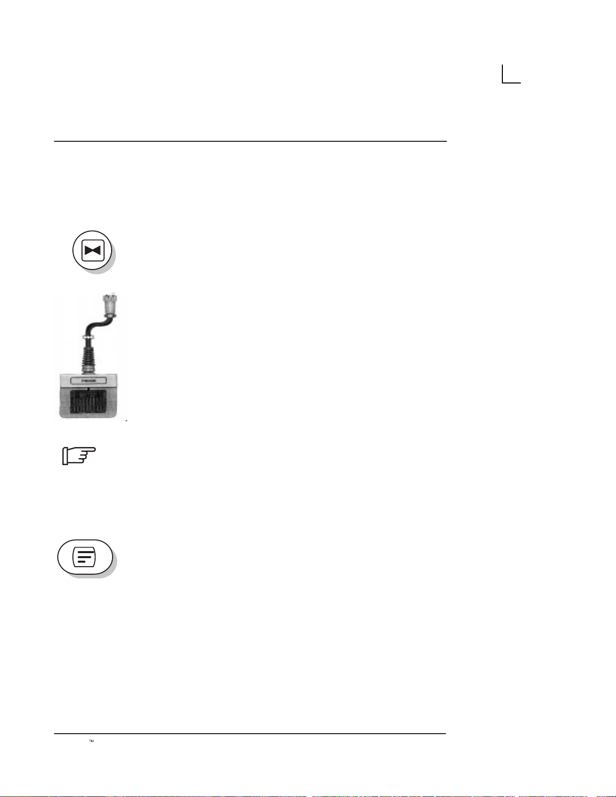
Freezing an Image
Freezing a real-time image stops all acquisition of
information into system memory. This allows for
measurements, annotations and printing.
Scan Adjustments
Press
A"
.
reactivate the image, press
Toggle
pressing the footswitch. The freeze LED button lights up
on the console.
NOTE: Deactivating Freeze erases all measurements
and calculations from the display (but not from the report
page). Selecting a new probe unfreezes the image.
Annotating the Image
FREEZE
FREEZE
to freeze an image. The LED lights. To
FREEZE
(Foot switch option) on and off by
again.
When
the cursor using the trackball anywhere on the image
and use alphanumeric keys to enter comments. (Press
CONTROL–C to set Home position of cursor, if required).
Press
COMMENT
Erasing Annotations
Use
left of the cursor. Comments also get erased at power off
or when
LOGIQt α100 User Manual
2211 157–100 Rev 0
COMMENT
RETURN
BACKSPACE
CLEAR
to move to the next line. Press
again to terminate the function.
or
is pressed, the cursor appears. Move
to erase individual characters to the
NEW PATIENT
are pressed.
77
Page 94

Scan Adjustments
Body Patterns
d
Selection Key
An additional way to annotate the image display is with
body patterns. Body patterns are a simple graphic of a
portion of the anatomy that is frequently scanned.
Body pattern is generally displayed in the lower left
corner of the screen. Its placement can vary with the
format of the display. eg. Dual B-Mode.
Along with the body graphic is a marker that illustrates
the probe position. This marker can be moved with the
TRACKBALL
the
GAIN/ROTATE
activated). The body pattern and probe marker can serve
as a reference for patient and probe positioning.
and rotated with the
knob (only when the
LEFT/RIGHT
FREEZE
keys or
key is
Press the
menu. The default Body Pattern Package is the
OB/GYN package.
Abdomen Body Patterns
1: SUP 2:LFT 3:RGT 4:LOB 5:ROB 6:PRN 7:BRS 8:NEC 9:LMA 0:RMA
0. RMA Right Mammo
SELECTION
Illustration 20. Abdomen Body Pattern Selections
1. SUP Supine
2. LFT Left Side
3. RGT Right Side
4. LOB Left Oblique
5. ROB Right Oblique
6. PRN Prone
7. BRS Breast
8. NEC Neck
9. LMA Left Mammo
key to select the Body Pattern
78
LOGIQt α100 User Manual
2211 157–100 Rev 0
Page 95

Selection Key (cont’d)
Scan Adjustments
Supine Right Oblique
Prone
Left
Breast
Illustration 21. Abdomen Package
Right
Neck
Left Oblique
Left Mammo Right Mammo
OB/GYN Body Patterns
1 MAMA 2 FTS1 3 FTS2 4 FTS3 5 FTS4 6 FTS5 7 UTRS1 8 UTRS2
Illustration 22. OB/GYN Body Pattern Selections
1. MAMA OB Patient
2. FTS1 Fetus 1
3. FTS2 Fetus 2
4. FTS3 Fetus 3
5. FTS4 Fetus 4
6. FTS5 Fetus 5
7. UTRS1 Uterus 1
8. UTRS2 Uterus 2
LOGIQt α100 User Manual
2211 157–100 Rev 0
79
Page 96

Scan Adjustments
Selection Key (cont’d)
Mama Fetus1 Fetus2 Fetus3
Fetus4 Fetus5 Uterus1 Uterus2
Veterinary Body Patterns
The following Veterinary body patterns are available for
Veterinary scans.
1. DG_SUP Dog Supine
2. DG_R Dog Right
3. DG_L Dog Left
4. CT_SUP Cat Supine
5. CT_R Cat Right
6. CT_L Cat Left
7. CW_UT Cow Uterus
8. CW_R Cow Right
9. CW_L Cow Left
10. HR_UT Horse Uterus
11. HR_R Horse Right
12. HR_L Horse Left
13. HR_FT Horse Front
14. HR_RR Horse Rear
Illustration 23. OB/GYN Package
80
LOGIQt α100 User Manual
2211 157–100 Rev 0
Page 97

Selection Key (cont’d)
Dog Supine Dog Right Dog Left
Cat Supine Cat Right Cat Left
Scan Adjustments
Cow Uterus Cow Right Cow Left
Horse Uterus Horse Right Horse Left
Horse Front Horse Rear
LOGIQt α100 User Manual
2211 157–100 Rev 0
Illustration 24 Veterinary Package
81
Page 98

Scan Adjustments
Selection Key (cont’d)
.
Rotate Keys
B B
NOTE: Pressing the SELECTION key at the end of each
menu (Abdomen, OB/GYN or Veterinary) takes you to
the next Body Pattern Package automatically.
Use the
angle within the selected Body Pattern. 30
step is possible.
The
probe marker angle only when the
activated.
Use the
LEFT/RIGHT
GAIN/ROTATE
TRACKBALL
keys to adjust scan probe marker
_
rotation per
knob can be used to adjust scan
FREEZE
for probe marker location.
key is
82
LOGIQt α100 User Manual
2211 157–100 Rev 0
Page 99

Overview
VCR Operations
An optional video cassette recorder is available for the
LOGIQ α100. The optional VCR is the Sony
SVO–9500MD.
CAUTION
External Video
j
ff
Record
.
Use only approved probes, peripherals or accessories.
Please refer to the Service Manual (2139768) for more
information about Peripherals/Accessories and their
connections.
Press the
video (i.e. VCR Playback) to be viewed on the
LOGIQ α100 system monitor.
Press the
the display monitor. It can be used to trigger a
videographic printer. In the Report Page, fields ‘Report
Date’ and ‘Reported by’ are printed in reverse video to
enable the doctor to edit those fields.
NOTE: SHIFT + RECORD can be used to print the
current Report page on a printer by connecting it to the
RS-232C serial port on the rear panel.
EXTERNAL VIDEO
RECORD
key to record the image which is on
key to enable an external
RS–232C Port shall be used with GE supplied cable
only.
Refer SV Manual 2139768 Section System Configuration
for RS–232C Pin out and, Section Renewal parts for the
Part number of the cable to be used.
LOGIQt α100 User Manual
2211 157–100 Rev 0
83
Page 100

VCR Operations
This page left blank intentionally.
84
LOGIQt α100 User Manual
2211 157–100 Rev 0
 Loading...