

Page 1

#"!
$!
! ! ! #
" #""
Page 2

Regulatory Requirement
This product complies with regulatory requirements of the following European
Directive 93/42/EEC concerning medical devices
This manual is a reference for the LOGIQ 400 PRO. It applies to all versions
of 5.01 software for the LOGIQ 400 ultrasound systems.
GE Medical Systems
GE Medical Systems: Telex 3797371
P.O. Box 414, Milwaukee, Wisconsin 53201 U.S.A.
(Asia, Pacific, Latin America, North America)
$% /+, &+ 1 -*() %
,#(. '+,*0 (+,!# (%$'" '
Page 3

Revision History
&# #$ "(
REV DATE REASON FOR CHANGE
0
1
February 7, 2000
February 23, 2000
Initial Release
Corrections
$
&# #$ "(
%$ "( !%"$#
$$# $"%
$"%
$"%
$"%
$"%
$"%
$"%
$"%
$"%
$"%
$"%
$"%
$"%
$"%
$"%
$"%
' $"%
Please verify that you are using the latest revision of this document. Information
pertaining to this document is maintained on GPC (GE Medical Systems Global
Product Configuration). If you need to know the latest revision, contact your
distributor, local GE Sales Representative or in the USA call the GE Ultrasound
Clinical Answer Center at 1-800-682-5327 or 262-524-5698.
LOGIQ 400 Basic User Manual
2260260–100 Rev . 1
Revision History A
Page 4

Revision History
This page left blank intentionally.
Revision History B
LOGIQ 400 Basic Users Manual
2260260–100 Rev . 1
Page 5

Regulatory Requirements
A
Regulatory Requirements
This product complies with the regulatory requirements of the
following:
S Council Directive 93/42/EEC concerning medical devices:
the label affixed to the product testifies compliance
to the Directive.
The location of the CE marking is shown on 2–24 of this
manual.
European registered place of business:
GE Medical Systems Europe
Quality Assurance Manager
BP 34
F 78533 BUC CEDEX France
Tel: +33 (0)1 30 70 40 40
.
For US
Only
S Medical Device Good Manufacturing Practice Manual
issued by the FDA (Food and Drug Administration,
Department of Health, USA).
S Underwriters’ Laboratories, Inc. (UL), an independent
testing laboratory.
S Canadian Standards Association (CSA).
S International Electrotechnical Commission (IEC),
international standards organizations, when applicable.
Caution: United States law restricts this device to sale or use by
or on the order of a physician.
S
General Electric Medical Systems
EN 46001 certified.
S The original document was written in English.
is ISO 9001 and
LOGIQ 400 Basic User Manual
2260260–100 Rev . 1
Regulatory Req 1
Page 6

Regulatory Requirements
NOTE: This equipment generates, uses and can radiate radio frequency energy. The
equipment may cause radio frequency interference to other medical and
non-medical devices and radio communications. To provide reasonable
protection against such interference, this product complies with emissions limits
for a Group 1, Class A Medical Devices Directive as stated in EN 60601–1–2.
However, there is no guarantee that interference will not occur in a particular
installation.
NOTE: If this equipment is found to cause interference (which may be determined by
turning the equipment on and off), the user (or qualified service personnel)
should attempt to correct the problem by one or more of the following
measure(s):
– reorient or relocate the affected device(s)
– increase the separation between the equipment and the affected device
– power the equipment from a source different from that of the affected device
– consult the point of purchase or service representative for further
suggestions
NOTE: The manufacturer is not responsible for any interference caused by using other
than recommended interconnect cables or by unauthorized changes or
modifications to this equipment. Unauthorized changes or modifications could
void the users’ authority to operate the equipment.
NOTE: To comply with the regulations on electromagnetic interference for a Class A
FCC Device, all interconnect cables to peripheral devices must be shielded and
properly grounded. Use of cables not properly shielded and grounded may
result in the equipment causing radio frequency interference in violation of the
FCC regulations.
NOTE: Do not use devices which intentionally transmit RF Signals (cellular phones,
transceivers, or radio controlled products) in the vicinity of the equipment as it
may cause performance outside the published specifications. Keep the power
to these type devices turned off when near this equipment.
The medical staff in charge of this equipment is required to instruct technicians,
patients, and other people who may be around this equipment to fully comply
with the above requirement.
Regulatory Req 2
LOGIQ 400 Basic Users Manual
2260260–100 Rev . 1
Page 7

Table of Contents
Table of Contents
VOLUME 1
Front Matter
Title Page
Revision History A. . . . . . . . . . . . . . . . . . . . . . . . . . . . . . . . . . . . . . . . .
Regulatory Requirements
Table of Contents Table of Contents 1. . . . . . . . . . . . . . . . . . . . . . . . . . . . . .
Chapter 1—Introduction
System Overview 1–2. . . . . . . . . . . . . . . . . . . . . . . . . . . . . . . . . . . . . . . . .
Attention 1–2. . . . . . . . . . . . . . . . . . . . . . . . . . . . . . . . . . . . . . . . . . . . . . . . . . . .
Documentation 1–2. . . . . . . . . . . . . . . . . . . . . . . . . . . . . . . . . . . . . . . . . . . . . .
Physical Principle Used 1–3. . . . . . . . . . . . . . . . . . . . . . . . . . . . . . . . . . . . . . .
General Indications for Use 1–4. . . . . . . . . . . . . . . . . . . . . . . . . . . . . . . . . . . .
Contraindications 1–5. . . . . . . . . . . . . . . . . . . . . . . . . . . . . . . . . . . . . . . . . . . .
Prescription Device 1–5. . . . . . . . . . . . . . . . . . . . . . . . . . . . . . . . . . . . . . . . . . .
LOGIQ 400/LOGIQ 400CL Functionality 1–6. . . . . . . . . . . . . . . . . . . . .
Regulatory Req 1. . . . . . . . . . . . . . . . . . . . . .
Who To Contact 1–9. . . . . . . . . . . . . . . . . . . . . . . . . . . . . . . . . . . . . . . . . .
Contacting GE Medical Systems—Ultrasound 1–9. . . . . . . . . . . . . . . . . . .
Manufacturer 1–12. . . . . . . . . . . . . . . . . . . . . . . . . . . . . . . . . . . . . . . . . . . . . . . .
How This Book is Organized 1–13. . . . . . . . . . . . . . . . . . . . . . . . . . . . . . .
Manual Content 1–13. . . . . . . . . . . . . . . . . . . . . . . . . . . . . . . . . . . . . . . . . . . . . .
Manual Format 1–15. . . . . . . . . . . . . . . . . . . . . . . . . . . . . . . . . . . . . . . . . . . . . .
Chapter 2—Safety
Safety Precautions 2–2. . . . . . . . . . . . . . . . . . . . . . . . . . . . . . . . . . . . . . . .
Precaution Levels 2–2. . . . . . . . . . . . . . . . . . . . . . . . . . . . . . . . . . . . . . . . . . . .
Hazard Symbols 2–3. . . . . . . . . . . . . . . . . . . . . . . . . . . . . . . . . . . . . . . . . . . . .
Patient Safety 2–4. . . . . . . . . . . . . . . . . . . . . . . . . . . . . . . . . . . . . . . . . . . . . . .
Equipment and Personnel Safety 2–6. . . . . . . . . . . . . . . . . . . . . . . . . . . . . . .
Device Labels 2–8. . . . . . . . . . . . . . . . . . . . . . . . . . . . . . . . . . . . . . . . . . . . . . .
Acoustic Output 2–17. . . . . . . . . . . . . . . . . . . . . . . . . . . . . . . . . . . . . . . . . . . . . .
Warning Label Locations 2–19. . . . . . . . . . . . . . . . . . . . . . . . . . . . . . . . . . . . . .
LOGIQ 400 Basic User Manual
2260260–100 Rev . 1
Table of Contents 1
Page 8

Table of Contents
Chapter 3—Preparing the System for Use
Site Requirements 3–2. . . . . . . . . . . . . . . . . . . . . . . . . . . . . . . . . . . . . . . .
Introduction 3–2. . . . . . . . . . . . . . . . . . . . . . . . . . . . . . . . . . . . . . . . . . . . . . . . .
Before the system arrives 3–3. . . . . . . . . . . . . . . . . . . . . . . . . . . . . . . . . . . . .
Environmental Requirements 3–4. . . . . . . . . . . . . . . . . . . . . . . . . . . . . . . . . .
Console Overview 3–5. . . . . . . . . . . . . . . . . . . . . . . . . . . . . . . . . . . . . . . .
Console graphics 3–5. . . . . . . . . . . . . . . . . . . . . . . . . . . . . . . . . . . . . . . . . . . .
Peripheral/Accessory Connection 3–8. . . . . . . . . . . . . . . . . . . . . . . . . . . . . .
System Positioning/Transporting 3–11. . . . . . . . . . . . . . . . . . . . . . . . . .
Moving the System 3–11. . . . . . . . . . . . . . . . . . . . . . . . . . . . . . . . . . . . . . . . . . .
Transporting the System 3–14. . . . . . . . . . . . . . . . . . . . . . . . . . . . . . . . . . . . . .
Wheels 3–15. . . . . . . . . . . . . . . . . . . . . . . . . . . . . . . . . . . . . . . . . . . . . . . . . . . . .
Powering On the System 3–16. . . . . . . . . . . . . . . . . . . . . . . . . . . . . . . . . .
Connecting and Using the System 3–16. . . . . . . . . . . . . . . . . . . . . . . . . . . . . .
Adjusting the Display Monitor 3–23. . . . . . . . . . . . . . . . . . . . . . . . . . . . .
Rotate, tilt, raise and lower the monitor 3–23. . . . . . . . . . . . . . . . . . . . . . . . .
Brightness and Contrast 3–24. . . . . . . . . . . . . . . . . . . . . . . . . . . . . . . . . . . . . .
Manual Degauss 3–27. . . . . . . . . . . . . . . . . . . . . . . . . . . . . . . . . . . . . . . . . . . . .
Speakers 3–28. . . . . . . . . . . . . . . . . . . . . . . . . . . . . . . . . . . . . . . . . . . . . . . . . . .
Probes 3–29. . . . . . . . . . . . . . . . . . . . . . . . . . . . . . . . . . . . . . . . . . . . . . . . . . .
Introduction 3–29. . . . . . . . . . . . . . . . . . . . . . . . . . . . . . . . . . . . . . . . . . . . . . . . .
Selecting a probe 3–29. . . . . . . . . . . . . . . . . . . . . . . . . . . . . . . . . . . . . . . . . . . .
Connecting the Probe 3–29. . . . . . . . . . . . . . . . . . . . . . . . . . . . . . . . . . . . . . . .
Cable Handling 3–31. . . . . . . . . . . . . . . . . . . . . . . . . . . . . . . . . . . . . . . . . . . . . .
Activating the Probe 3–31. . . . . . . . . . . . . . . . . . . . . . . . . . . . . . . . . . . . . . . . . .
Deactivating the Probe 3–32. . . . . . . . . . . . . . . . . . . . . . . . . . . . . . . . . . . . . . . .
Disconnecting the Probe 3–33. . . . . . . . . . . . . . . . . . . . . . . . . . . . . . . . . . . . . .
Transporting Probes 3–33. . . . . . . . . . . . . . . . . . . . . . . . . . . . . . . . . . . . . . . . . .
Storing the Probe 3–33. . . . . . . . . . . . . . . . . . . . . . . . . . . . . . . . . . . . . . . . . . . .
Operator Controls 3–34. . . . . . . . . . . . . . . . . . . . . . . . . . . . . . . . . . . . . . . .
Control Panel Map 3–34. . . . . . . . . . . . . . . . . . . . . . . . . . . . . . . . . . . . . . . . . . .
Key Illumination 3–35. . . . . . . . . . . . . . . . . . . . . . . . . . . . . . . . . . . . . . . . . . . . . .
Keyboard 3–36. . . . . . . . . . . . . . . . . . . . . . . . . . . . . . . . . . . . . . . . . . . . . . . . . . .
Soft Menu Control Panel 3–37. . . . . . . . . . . . . . . . . . . . . . . . . . . . . . . . . . . . . .
Mode, Display and Record 3–40. . . . . . . . . . . . . . . . . . . . . . . . . . . . . . . . . . . .
Measurement and Annotation 3–42. . . . . . . . . . . . . . . . . . . . . . . . . . . . . . . . .
Table of Contents 2
LOGIQ 400 Basic Users Manual
2260260–100 Rev . 1
Page 9

Table of Contents
Chapter 4—Preparing for an Exam
Beginning an Exam 4–2. . . . . . . . . . . . . . . . . . . . . . . . . . . . . . . . . . . . . . .
Introduction 4–2. . . . . . . . . . . . . . . . . . . . . . . . . . . . . . . . . . . . . . . . . . . . . . . . .
Beginning a New Patient 4–3. . . . . . . . . . . . . . . . . . . . . . . . . . . . . . . . . . . . . .
ID/Name 4–6. . . . . . . . . . . . . . . . . . . . . . . . . . . . . . . . . . . . . . . . . . . . . . . . . . . .
Exam Application Preset Selection 4–7. . . . . . . . . . . . . . . . . . . . . . . . .
Introduction 4–7. . . . . . . . . . . . . . . . . . . . . . . . . . . . . . . . . . . . . . . . . . . . . . . . .
Selecting a probe 4–7. . . . . . . . . . . . . . . . . . . . . . . . . . . . . . . . . . . . . . . . . . . .
Chapter 5—Modes
B-Mode 5–2. . . . . . . . . . . . . . . . . . . . . . . . . . . . . . . . . . . . . . . . . . . . . . . . . .
Introduction 5–2. . . . . . . . . . . . . . . . . . . . . . . . . . . . . . . . . . . . . . . . . . . . . . . . .
B-Mode Key Operation 5–2. . . . . . . . . . . . . . . . . . . . . . . . . . . . . . . . . . . . . . .
Reading the B-Mode Display 5–3. . . . . . . . . . . . . . . . . . . . . . . . . . . . . . . . . .
Optimizing the Image 5–9. . . . . . . . . . . . . . . . . . . . . . . . . . . . . . . . . . . . . . . . .
Adding Color 5–26. . . . . . . . . . . . . . . . . . . . . . . . . . . . . . . . . . . . . . . . . . . . .
Gray Scale Color 5–26. . . . . . . . . . . . . . . . . . . . . . . . . . . . . . . . . . . . . . . . . . . . .
Color Flow Mode 5–26. . . . . . . . . . . . . . . . . . . . . . . . . . . . . . . . . . . . . . . . . . . . .
Activating Color Flow 5–27. . . . . . . . . . . . . . . . . . . . . . . . . . . . . . . . . . . . . . . . .
Reading the Color Flow Display 5–28. . . . . . . . . . . . . . . . . . . . . . . . . . . . . . . .
Optimizing the Color Flow Image 5–29. . . . . . . . . . . . . . . . . . . . . . . . . . . . . . .
Power Doppler Imaging (option) 5–43. . . . . . . . . . . . . . . . . . . . . . . . . . . . . . .
Doppler 5–44. . . . . . . . . . . . . . . . . . . . . . . . . . . . . . . . . . . . . . . . . . . . . . . . . .
Introduction 5–44. . . . . . . . . . . . . . . . . . . . . . . . . . . . . . . . . . . . . . . . . . . . . . . . .
Pulsed Wave Doppler 5–45. . . . . . . . . . . . . . . . . . . . . . . . . . . . . . . . . . . . . . . . .
Continuous Wave Doppler 5–47. . . . . . . . . . . . . . . . . . . . . . . . . . . . . . . . . . . .
Reading the Doppler Display 5–48. . . . . . . . . . . . . . . . . . . . . . . . . . . . . . . . . .
Activating Doppler Mode 5–50. . . . . . . . . . . . . . . . . . . . . . . . . . . . . . . . . . . . . .
Doppler Optimization 5–51. . . . . . . . . . . . . . . . . . . . . . . . . . . . . . . . . . . . . . . . .
M-Mode 5–65. . . . . . . . . . . . . . . . . . . . . . . . . . . . . . . . . . . . . . . . . . . . . . . . . .
Introduction 5–65. . . . . . . . . . . . . . . . . . . . . . . . . . . . . . . . . . . . . . . . . . . . . . . . .
Reading the M-Mode or Doppler Spectrum Only Display 5–65. . . . . . . . . .
Reading the Dual Doppler Spectrum Only Display 5–66. . . . . . . . . . . . . . . .
Optimizing the Timeline 5–67. . . . . . . . . . . . . . . . . . . . . . . . . . . . . . . . . . . . . . .
3DvieW Mode (Option) 5–73. . . . . . . . . . . . . . . . . . . . . . . . . . . . . . . . . . . .
Overview 5–73. . . . . . . . . . . . . . . . . . . . . . . . . . . . . . . . . . . . . . . . . . . . . . . . . . .
LOGIQ 400 Basic User Manual
2260260–100 Rev . 1
Table of Contents 3
Page 10

Table of Contents
3D-Surface Mode (Option) 5–74. . . . . . . . . . . . . . . . . . . . . . . . . . . . . . . . .
Overview 5–74. . . . . . . . . . . . . . . . . . . . . . . . . . . . . . . . . . . . . . . . . . . . . . . . . . .
Mixed Mode Display Formats 5–75. . . . . . . . . . . . . . . . . . . . . . . . . . . . . .
Display Formats 5–75. . . . . . . . . . . . . . . . . . . . . . . . . . . . . . . . . . . . . . . . . . . . .
Chapter 6—Scanning/Display Functions
Zooming an Image 6–2. . . . . . . . . . . . . . . . . . . . . . . . . . . . . . . . . . . . . . . .
Introduction 6–2. . . . . . . . . . . . . . . . . . . . . . . . . . . . . . . . . . . . . . . . . . . . . . . . .
Zoom Methods 6–2. . . . . . . . . . . . . . . . . . . . . . . . . . . . . . . . . . . . . . . . . . . . . .
Zooming an M-Mode Image 6–4. . . . . . . . . . . . . . . . . . . . . . . . . . . . . . . . . . .
Multi–Image Zoom 6–5. . . . . . . . . . . . . . . . . . . . . . . . . . . . . . . . . . . . . . . . . . .
Freezing an Image 6–6. . . . . . . . . . . . . . . . . . . . . . . . . . . . . . . . . . . . . . . .
Introduction 6–6. . . . . . . . . . . . . . . . . . . . . . . . . . . . . . . . . . . . . . . . . . . . . . . . .
Freezing an Image (Freeze Key) 6–7. . . . . . . . . . . . . . . . . . . . . . . . . . . . . . .
Freezing an Image (Foot Switch option) 6–7. . . . . . . . . . . . . . . . . . . . . . . . .
Using Cine 6–8. . . . . . . . . . . . . . . . . . . . . . . . . . . . . . . . . . . . . . . . . . . . . . .
Introduction 6–8. . . . . . . . . . . . . . . . . . . . . . . . . . . . . . . . . . . . . . . . . . . . . . . . .
Accessing Cine 6–10. . . . . . . . . . . . . . . . . . . . . . . . . . . . . . . . . . . . . . . . . . . . . .
Using Cine Loop 6–11. . . . . . . . . . . . . . . . . . . . . . . . . . . . . . . . . . . . . . . . . . . . .
Cine Loop Speed 6–13. . . . . . . . . . . . . . . . . . . . . . . . . . . . . . . . . . . . . . . . . . . .
Multipl CINE 6–13. . . . . . . . . . . . . . . . . . . . . . . . . . . . . . . . . . . . . . . . . . . . . . . . .
Side Change 6–14. . . . . . . . . . . . . . . . . . . . . . . . . . . . . . . . . . . . . . . . . . . . . . . .
CINE Gauge 6–14. . . . . . . . . . . . . . . . . . . . . . . . . . . . . . . . . . . . . . . . . . . . . . . .
CINE Capture (option) 6–14. . . . . . . . . . . . . . . . . . . . . . . . . . . . . . . . . . . . . . . .
Exiting Cine 6–15. . . . . . . . . . . . . . . . . . . . . . . . . . . . . . . . . . . . . . . . . . . . . . . . .
Helpful Hints 6–15. . . . . . . . . . . . . . . . . . . . . . . . . . . . . . . . . . . . . . . . . . . . . . . .
ECG/Cine Gauge/Image Tracking 6–15. . . . . . . . . . . . . . . . . . . . . . . . . . . . . .
Annotating an Image 6–16. . . . . . . . . . . . . . . . . . . . . . . . . . . . . . . . . . . . . .
Introduction 6–16. . . . . . . . . . . . . . . . . . . . . . . . . . . . . . . . . . . . . . . . . . . . . . . . .
Annotation Library 6–19. . . . . . . . . . . . . . . . . . . . . . . . . . . . . . . . . . . . . . . . . . . .
Adding Comments to an Image 6–21. . . . . . . . . . . . . . . . . . . . . . . . . . . . . . . .
Special Annotation Keys 6–22. . . . . . . . . . . . . . . . . . . . . . . . . . . . . . . . . . . . . .
Editing Annotations 6–26. . . . . . . . . . . . . . . . . . . . . . . . . . . . . . . . . . . . . . . . . . .
Body Patterns 6–27. . . . . . . . . . . . . . . . . . . . . . . . . . . . . . . . . . . . . . . . . . . . . . .
Table of Contents 4
LOGIQ 400 Basic Users Manual
2260260–100 Rev . 1
Page 11

Table of Contents
Chapter 7—General Measurements and Calculations
Introduction 7–2. . . . . . . . . . . . . . . . . . . . . . . . . . . . . . . . . . . . . . . . . . . . . .
Overview 7–2. . . . . . . . . . . . . . . . . . . . . . . . . . . . . . . . . . . . . . . . . . . . . . . . . . .
Measurement Controls 7–3. . . . . . . . . . . . . . . . . . . . . . . . . . . . . . . . . . . . . . . .
Cursors 7–4. . . . . . . . . . . . . . . . . . . . . . . . . . . . . . . . . . . . . . . . . . . . . . . . . . . . .
General Mode Measurements Method 7–4. . . . . . . . . . . . . . . . . . . . . . . . . .
Measurement Key 7–5. . . . . . . . . . . . . . . . . . . . . . . . . . . . . . . . . . . . . . . . . . . .
General Instructions 7–6. . . . . . . . . . . . . . . . . . . . . . . . . . . . . . . . . . . . . . . . . .
Erasing Measurements 7–6. . . . . . . . . . . . . . . . . . . . . . . . . . . . . . . . . . . . . . .
Mode Measurements 7–7. . . . . . . . . . . . . . . . . . . . . . . . . . . . . . . . . . . . . .
B-Mode Measurements 7–7. . . . . . . . . . . . . . . . . . . . . . . . . . . . . . . . . . . . . . .
CFM B-Mode Measurements 7–12. . . . . . . . . . . . . . . . . . . . . . . . . . . . . . . . . .
Doppler Mode Measurements 7–14. . . . . . . . . . . . . . . . . . . . . . . . . . . . . . . . .
M-Mode Measurements 7–19. . . . . . . . . . . . . . . . . . . . . . . . . . . . . . . . . . . . . . .
Chapter 8—Abdomen and Small Parts
General Calculations 8–2. . . . . . . . . . . . . . . . . . . . . . . . . . . . . . . . . . . . . .
Overview 8–2. . . . . . . . . . . . . . . . . . . . . . . . . . . . . . . . . . . . . . . . . . . . . . . . . . .
Volume 8–2. . . . . . . . . . . . . . . . . . . . . . . . . . . . . . . . . . . . . . . . . . . . . . . . . . . . .
Angle 8–3. . . . . . . . . . . . . . . . . . . . . . . . . . . . . . . . . . . . . . . . . . . . . . . . . . . . . . .
Stenosis Ratio (% stenosis) 8–3. . . . . . . . . . . . . . . . . . . . . . . . . . . . . . . . . . .
S/D Ratio, RI, A/B Ratio or PI 8–3. . . . . . . . . . . . . . . . . . . . . . . . . . . . . . . . . .
Heart Rate 8–3. . . . . . . . . . . . . . . . . . . . . . . . . . . . . . . . . . . . . . . . . . . . . . . . . .
Trace Auto 8–3. . . . . . . . . . . . . . . . . . . . . . . . . . . . . . . . . . . . . . . . . . . . . . . . . .
Max PG 8–3. . . . . . . . . . . . . . . . . . . . . . . . . . . . . . . . . . . . . . . . . . . . . . . . . . . . .
Mean PG 8–3. . . . . . . . . . . . . . . . . . . . . . . . . . . . . . . . . . . . . . . . . . . . . . . . . . .
Cardiac Output (CO) 8–4. . . . . . . . . . . . . . . . . . . . . . . . . . . . . . . . . . . . . . . . .
Stroke Volume Ratio (SV) 8–5. . . . . . . . . . . . . . . . . . . . . . . . . . . . . . . . . . . . .
Heart Rate (HR) 8–6. . . . . . . . . . . . . . . . . . . . . . . . . . . . . . . . . . . . . . . . . . . . .
Flow Volume (FV) 8–7. . . . . . . . . . . . . . . . . . . . . . . . . . . . . . . . . . . . . . . . . . . .
Trace Auto 8–8. . . . . . . . . . . . . . . . . . . . . . . . . . . . . . . . . . . . . . . . . . . . . . . . . .
Flow Volume Output (FVO) 8–8. . . . . . . . . . . . . . . . . . . . . . . . . . . . . . . . . . . .
Helpful hints 8–8. . . . . . . . . . . . . . . . . . . . . . . . . . . . . . . . . . . . . . . . . . . . . . . . .
Hip Dysplasia Measurement 8–9. . . . . . . . . . . . . . . . . . . . . . . . . . . . . . . . . . .
General Calculation Formulas 8–11. . . . . . . . . . . . . . . . . . . . . . . . . . . . . . . . .
LOGIQ 400 Basic User Manual
2260260–100 Rev . 1
Table of Contents 5
Page 12

Table of Contents
Chapter 9—OB/GYN (Basic OB software option)
Exam Preparation 9–2. . . . . . . . . . . . . . . . . . . . . . . . . . . . . . . . . . . . . . . . .
Overview 9–2. . . . . . . . . . . . . . . . . . . . . . . . . . . . . . . . . . . . . . . . . . . . . . . . . . .
Fetal Doppler 9–3. . . . . . . . . . . . . . . . . . . . . . . . . . . . . . . . . . . . . . . . . . . . .
Doppler Mode for Fetal Exams 9–3. . . . . . . . . . . . . . . . . . . . . . . . . . . . . . . . .
Acoustic Output 9–4. . . . . . . . . . . . . . . . . . . . . . . . . . . . . . . . . . . . . . . . . .
Considerations 9–4. . . . . . . . . . . . . . . . . . . . . . . . . . . . . . . . . . . . . . . . . . . . . .
OB Measurements and Formulas 9–5. . . . . . . . . . . . . . . . . . . . . . . . . .
Introduction 9–5. . . . . . . . . . . . . . . . . . . . . . . . . . . . . . . . . . . . . . . . . . . . . . . . .
OB Format Selection 9–5. . . . . . . . . . . . . . . . . . . . . . . . . . . . . . . . . . . . . . . . .
OB Measurement Soft Menus and Formulas 9–6. . . . . . . . . . . . . . . . . . . . .
Helpful Hints 9–26. . . . . . . . . . . . . . . . . . . . . . . . . . . . . . . . . . . . . . . . . . . . . . . .
OB Summary Reports 9–27. . . . . . . . . . . . . . . . . . . . . . . . . . . . . . . . . . . . .
Starting an Exam 9–27. . . . . . . . . . . . . . . . . . . . . . . . . . . . . . . . . . . . . . . . . . . .
OB Report Page Layout 9–28. . . . . . . . . . . . . . . . . . . . . . . . . . . . . . . . . . . . . . .
Editing the Report 9–35. . . . . . . . . . . . . . . . . . . . . . . . . . . . . . . . . . . . . . . . . . . .
Recording Summary Reports 9–37. . . . . . . . . . . . . . . . . . . . . . . . . . . . . . . . . .
Anatomical Survey 9–38. . . . . . . . . . . . . . . . . . . . . . . . . . . . . . . . . . . . . . . .
Overview 9–38. . . . . . . . . . . . . . . . . . . . . . . . . . . . . . . . . . . . . . . . . . . . . . . . . . .
Editing 9–39. . . . . . . . . . . . . . . . . . . . . . . . . . . . . . . . . . . . . . . . . . . . . . . . . . . . . .
User Programmed Features 9–39. . . . . . . . . . . . . . . . . . . . . . . . . . . . . . . . . . .
OB Graphs 9–40. . . . . . . . . . . . . . . . . . . . . . . . . . . . . . . . . . . . . . . . . . . . . . .
Overview 9–40. . . . . . . . . . . . . . . . . . . . . . . . . . . . . . . . . . . . . . . . . . . . . . . . . . .
OB Graph Selection 9–41. . . . . . . . . . . . . . . . . . . . . . . . . . . . . . . . . . . . . . . . . .
Advanced Obstetrical Options 9–44. . . . . . . . . . . . . . . . . . . . . . . . . . . . .
Options 9–44. . . . . . . . . . . . . . . . . . . . . . . . . . . . . . . . . . . . . . . . . . . . . . . . . . . . .
GYN Measurements 9–45. . . . . . . . . . . . . . . . . . . . . . . . . . . . . . . . . . . . . . .
B-Mode 9–45. . . . . . . . . . . . . . . . . . . . . . . . . . . . . . . . . . . . . . . . . . . . . . . . . . . . .
Doppler Mode 9–47. . . . . . . . . . . . . . . . . . . . . . . . . . . . . . . . . . . . . . . . . . . . . . .
GYN Summary Report 9–49. . . . . . . . . . . . . . . . . . . . . . . . . . . . . . . . . . . . .
GYN Report Pages 9–49. . . . . . . . . . . . . . . . . . . . . . . . . . . . . . . . . . . . . . . . . . .
Calculation Formulas 9–51. . . . . . . . . . . . . . . . . . . . . . . . . . . . . . . . . . . . . . . . .
Table of Contents 6
LOGIQ 400 Basic Users Manual
2260260–100 Rev . 1
Page 13

Table of Contents
Chapter 10—Cardiology (software option)
Introduction 10–3. . . . . . . . . . . . . . . . . . . . . . . . . . . . . . . . . . . . . . . . . . . . . .
Overview 10–3. . . . . . . . . . . . . . . . . . . . . . . . . . . . . . . . . . . . . . . . . . . . . . . . . . .
Report Pages 10–5. . . . . . . . . . . . . . . . . . . . . . . . . . . . . . . . . . . . . . . . . . . . . . . .
BSA Calculation Methods 10–6. . . . . . . . . . . . . . . . . . . . . . . . . . . . . . . . . . . . .
Measuring Heart Rate (HR) 10–6. . . . . . . . . . . . . . . . . . . . . . . . . . . . . . . . . . .
LV Measurement Methods 10–7. . . . . . . . . . . . . . . . . . . . . . . . . . . . . . . . .
Cubed Method 10–7. . . . . . . . . . . . . . . . . . . . . . . . . . . . . . . . . . . . . . . . . . . . . . .
Teichholz Method 10–9. . . . . . . . . . . . . . . . . . . . . . . . . . . . . . . . . . . . . . . . . . . .
Bullet Method 10–11. . . . . . . . . . . . . . . . . . . . . . . . . . . . . . . . . . . . . . . . . . . . . . . .
Modified Simpson’s Rule Method 10–13. . . . . . . . . . . . . . . . . . . . . . . . . . . . . . .
Single Plane Ellipsoid Method 10–15. . . . . . . . . . . . . . . . . . . . . . . . . . . . . . . . .
Bi Plane Ellipsoid Methods 10–17. . . . . . . . . . . . . . . . . . . . . . . . . . . . . . . . . . . .
Additional Cardiology Calculations 10–19. . . . . . . . . . . . . . . . . . . . . . . .
Volume 10–19. . . . . . . . . . . . . . . . . . . . . . . . . . . . . . . . . . . . . . . . . . . . . . . . . . . . .
Angle 10–22. . . . . . . . . . . . . . . . . . . . . . . . . . . . . . . . . . . . . . . . . . . . . . . . . . . . . . .
% Stenosis (stenosis ratio) 10–23. . . . . . . . . . . . . . . . . . . . . . . . . . . . . . . . . . . .
PHT (Pressure Half Time) 10–24. . . . . . . . . . . . . . . . . . . . . . . . . . . . . . . . . . . . .
MVA (Mitral Valve Area) 10–24. . . . . . . . . . . . . . . . . . . . . . . . . . . . . . . . . . . . . . .
ET (Ejection Time) 10–25. . . . . . . . . . . . . . . . . . . . . . . . . . . . . . . . . . . . . . . . . . .
Max PG 10–26. . . . . . . . . . . . . . . . . . . . . . . . . . . . . . . . . . . . . . . . . . . . . . . . . . . . .
Mean PG 10–27. . . . . . . . . . . . . . . . . . . . . . . . . . . . . . . . . . . . . . . . . . . . . . . . . . .
Trace Auto 10–28. . . . . . . . . . . . . . . . . . . . . . . . . . . . . . . . . . . . . . . . . . . . . . . . . .
S/D (D/S) Ratio, RI, A/B Ratio or PI 10–29. . . . . . . . . . . . . . . . . . . . . . . . . . . . .
Heart Rate (HR) 10–30. . . . . . . . . . . . . . . . . . . . . . . . . . . . . . . . . . . . . . . . . . . . .
Transf Calcs 10–30. . . . . . . . . . . . . . . . . . . . . . . . . . . . . . . . . . . . . . . . . . . . . . . . .
ECG Option 10–31. . . . . . . . . . . . . . . . . . . . . . . . . . . . . . . . . . . . . . . . . . . . . .
Overview 10–31. . . . . . . . . . . . . . . . . . . . . . . . . . . . . . . . . . . . . . . . . . . . . . . . . . .
Physio Sweep Speed 10–32. . . . . . . . . . . . . . . . . . . . . . . . . . . . . . . . . . . . . . . . .
ECG Sub-Menu 10–32. . . . . . . . . . . . . . . . . . . . . . . . . . . . . . . . . . . . . . . . . . . . . .
ECG Lead Placement 10–33. . . . . . . . . . . . . . . . . . . . . . . . . . . . . . . . . . . . . . . .
ECG Sync Mark Display 10–33. . . . . . . . . . . . . . . . . . . . . . . . . . . . . . . . . . . . . .
ECG Sub-Menu Page 1 10–34. . . . . . . . . . . . . . . . . . . . . . . . . . . . . . . . . . . . . . .
ECG Gain Pages 2 and 3 10–36. . . . . . . . . . . . . . . . . . . . . . . . . . . . . . . . . . . . .
ECG/Cine Gauge/Image Tracking 10–36. . . . . . . . . . . . . . . . . . . . . . . . . . . . . .
Advanced Cardiac Calculations (AMCAL option) 10–37. . . . . . . . . . . .
Overview 10–37. . . . . . . . . . . . . . . . . . . . . . . . . . . . . . . . . . . . . . . . . . . . . . . . . . .
LOGIQ 400 Basic User Manual
2260260–100 Rev . 1
Table of Contents 7
Page 14

Table of Contents
Chapter 11—Vascular (software option)
Exam Preparation 11–2. . . . . . . . . . . . . . . . . . . . . . . . . . . . . . . . . . . . . . . . .
Introduction 11–2. . . . . . . . . . . . . . . . . . . . . . . . . . . . . . . . . . . . . . . . . . . . . . . . .
General Guidelines 11–2. . . . . . . . . . . . . . . . . . . . . . . . . . . . . . . . . . . . . . . . . . .
Measurements 11–3. . . . . . . . . . . . . . . . . . . . . . . . . . . . . . . . . . . . . . . . . . . .
Carotid Artery Measurements 11–3. . . . . . . . . . . . . . . . . . . . . . . . . . . . . . . . . .
Heart Rate (HR) 11–5. . . . . . . . . . . . . . . . . . . . . . . . . . . . . . . . . . . . . . . . . . . . .
Trace Auto 11–5. . . . . . . . . . . . . . . . . . . . . . . . . . . . . . . . . . . . . . . . . . . . . . . . . .
Helpful Hints 11–5. . . . . . . . . . . . . . . . . . . . . . . . . . . . . . . . . . . . . . . . . . . . . . . .
Vascular Summary Report 11–6. . . . . . . . . . . . . . . . . . . . . . . . . . . . . . . . .
Introduction 11–6. . . . . . . . . . . . . . . . . . . . . . . . . . . . . . . . . . . . . . . . . . . . . . . . .
Displaying the Summary Report 11–6. . . . . . . . . . . . . . . . . . . . . . . . . . . . . . . .
Editing the Summary Report 11–7. . . . . . . . . . . . . . . . . . . . . . . . . . . . . . . . . . .
Recording Summary Reports 11–8. . . . . . . . . . . . . . . . . . . . . . . . . . . . . . . . . .
Vascular Calculation Formulas 11–9. . . . . . . . . . . . . . . . . . . . . . . . . . . . . . . . .
Advanced Vascular (software option) 11–10. . . . . . . . . . . . . . . . . . . . . . .
Overview 11–10. . . . . . . . . . . . . . . . . . . . . . . . . . . . . . . . . . . . . . . . . . . . . . . . . . .
Menu Selections 11–10. . . . . . . . . . . . . . . . . . . . . . . . . . . . . . . . . . . . . . . . . . . . .
Chapter 12—Urology
Urology Basic Calculations 12–2. . . . . . . . . . . . . . . . . . . . . . . . . . . . . . . .
Overview 12–2. . . . . . . . . . . . . . . . . . . . . . . . . . . . . . . . . . . . . . . . . . . . . . . . . . .
Presumed Circle Area Ratio (PCAR) 12–3. . . . . . . . . . . . . . . . . . . . . . . . . . . .
Stepper Volume (STVOL) 12–3. . . . . . . . . . . . . . . . . . . . . . . . . . . . . . . . . . . . .
Urology Calculation (software option) 12–5. . . . . . . . . . . . . . . . . . . . . .
Urology Summary Report 12–5. . . . . . . . . . . . . . . . . . . . . . . . . . . . . . . . . . . . .
Stepper Volume Calculation 12–8. . . . . . . . . . . . . . . . . . . . . . . . . . . . . . . . . . .
Table of Contents 8
LOGIQ 400 Basic Users Manual
2260260–100 Rev . 1
Page 15

Table of Contents
Chapter 13—Recording Images
Recording Images 13–2. . . . . . . . . . . . . . . . . . . . . . . . . . . . . . . . . . . . . . . .
Image Memory 13–2. . . . . . . . . . . . . . . . . . . . . . . . . . . . . . . . . . . . . . . . . . . . . .
Recall 13–4. . . . . . . . . . . . . . . . . . . . . . . . . . . . . . . . . . . . . . . . . . . . . . . . . . . . . .
Helpful hints 13–4. . . . . . . . . . . . . . . . . . . . . . . . . . . . . . . . . . . . . . . . . . . . . . . . .
Peripheral Devices 13–5. . . . . . . . . . . . . . . . . . . . . . . . . . . . . . . . . . . . . . . . . . .
Video Signal Specifications 13–16. . . . . . . . . . . . . . . . . . . . . . . . . . . . . . . . . . . .
Maintenance 13–16. . . . . . . . . . . . . . . . . . . . . . . . . . . . . . . . . . . . . . . . . . . . . . . .
Image Archive (option) 13–17. . . . . . . . . . . . . . . . . . . . . . . . . . . . . . . . . . . . . . . .
Advanced Recording Option (software option) 13–33. . . . . . . . . . . . . .
DICOM 13–33. . . . . . . . . . . . . . . . . . . . . . . . . . . . . . . . . . . . . . . . . . . . . . . . . . . . .
Chapter 14—Customizing Your System
Time Adjustment 14–3. . . . . . . . . . . . . . . . . . . . . . . . . . . . . . . . . . . . . . . . .
Overview 14–3. . . . . . . . . . . . . . . . . . . . . . . . . . . . . . . . . . . . . . . . . . . . . . . . . . .
Time Adjustment 14–3. . . . . . . . . . . . . . . . . . . . . . . . . . . . . . . . . . . . . . . . . . . . .
Preset Parameters 14–5. . . . . . . . . . . . . . . . . . . . . . . . . . . . . . . . . . . . . . . .
Overview 14–5. . . . . . . . . . . . . . . . . . . . . . . . . . . . . . . . . . . . . . . . . . . . . . . . . . .
Custom Display 14–7. . . . . . . . . . . . . . . . . . . . . . . . . . . . . . . . . . . . . . . . . . .
Overview 14–7. . . . . . . . . . . . . . . . . . . . . . . . . . . . . . . . . . . . . . . . . . . . . . . . . . .
Parameter Menu Command Lines 14–8. . . . . . . . . . . . . . . . . . . . . . . . . . . . . .
Changing a Parameter Value 14–10. . . . . . . . . . . . . . . . . . . . . . . . . . . . . . . . . .
Custom Display Contents 14–12. . . . . . . . . . . . . . . . . . . . . . . . . . . . . . . . . . . . .
Page 1 of 18 (Imaging Parameter 1 – Probe Dependent 1) 14–13. . . . . . . .
Page 2 of 18 (Imaging Parameter 2 – Probe Dependent 2) 14–15. . . . . . . .
Page 3 of 18 (Imaging Parameter 3 – Probe Dependent 3) 14–18. . . . . . . .
Page 4 of 18 (Imaging Parameter 4 – Probe Dependent 4) 14–20. . . . . . . .
Page 5 of 18 (Imaging Parameter 5 – Probe Dependent 5) 14–22. . . . . . . .
Page 6 of 18 (Imaging Parameter 6 – Probe Dependent 6) 14–23. . . . . . . .
Page 7 of 18 (Imaging Parameter 7 – Probe Dependent 7) 14–25. . . . . . . .
Page 8 of 18 (Imaging Parameter 8 – Probe Dependent 8) 14–26. . . . . . . .
Page 9 of 18 (Imaging Parameter 9) 14–28. . . . . . . . . . . . . . . . . . . . . . . . . . . .
Page 10 of 18 (Imaging Parameter 10) 14–29. . . . . . . . . . . . . . . . . . . . . . . . . .
Page 11 of 18 (Imaging Parameter 11) 14–31. . . . . . . . . . . . . . . . . . . . . . . . . .
Page 12 of 18 (Imaging Parameter 12) 14–32. . . . . . . . . . . . . . . . . . . . . . . . . .
LOGIQ 400 Basic User Manual
2260260–100 Rev . 1
Table of Contents 9
Page 16

Table of Contents
Page 13 of 18 (Imaging Parameter 13) 14–34. . . . . . . . . . . . . . . . . . . . . . . . . .
Page 14 of 18 (Imaging Parameter 14) 14–37. . . . . . . . . . . . . . . . . . . . . . . . . .
Page 15 of 18 (Imaging Parameter 15) 14–39. . . . . . . . . . . . . . . . . . . . . . . . . .
Page 16 of 18 (Imaging Parameter 16) 14–41. . . . . . . . . . . . . . . . . . . . . . . . . .
Page 17 of 18 (Imaging Parameter 17) 14–42. . . . . . . . . . . . . . . . . . . . . . . . . .
Page 18 of 18 (Imaging Parameter 18) 14–44. . . . . . . . . . . . . . . . . . . . . . . . . .
System Parameters 14–46. . . . . . . . . . . . . . . . . . . . . . . . . . . . . . . . . . . . . . .
Overview 14–46. . . . . . . . . . . . . . . . . . . . . . . . . . . . . . . . . . . . . . . . . . . . . . . . . . .
System Parameters Contents 14–47. . . . . . . . . . . . . . . . . . . . . . . . . . . . . . . . . .
Page 1 of 7 (System Setup) 14–48. . . . . . . . . . . . . . . . . . . . . . . . . . . . . . . . . . .
Page 2 of 7 (System Setup) 14–50. . . . . . . . . . . . . . . . . . . . . . . . . . . . . . . . . . .
Page 3 of 7 (System Setup) 14–53. . . . . . . . . . . . . . . . . . . . . . . . . . . . . . . . . . .
Page 4 of 7 (System Setup – Body Pattern) 14–54. . . . . . . . . . . . . . . . . . . . .
Page 5 of 7 (System Setup – Recording) 14–58. . . . . . . . . . . . . . . . . . . . . . . .
Page 6 of 7 (System Setup – User ID and Password) 14–60. . . . . . . . . . . . .
Page 7 of 7 (DICOM) 14–62. . . . . . . . . . . . . . . . . . . . . . . . . . . . . . . . . . . . . . . . .
Preset Program 14–63. . . . . . . . . . . . . . . . . . . . . . . . . . . . . . . . . . . . . . . . . . .
Overview 14–63. . . . . . . . . . . . . . . . . . . . . . . . . . . . . . . . . . . . . . . . . . . . . . . . . . .
Preset Program Contents 14–64. . . . . . . . . . . . . . . . . . . . . . . . . . . . . . . . . . . . .
Page 1 of 10 (Application) 14–65. . . . . . . . . . . . . . . . . . . . . . . . . . . . . . . . . . . . .
Page 2 of 10 (Application) 14–66. . . . . . . . . . . . . . . . . . . . . . . . . . . . . . . . . . . . .
Page 3 of 10 (Application – Measurement) 14–67. . . . . . . . . . . . . . . . . . . . . .
Page 4 of 10 (Application – Measurement) 14–70. . . . . . . . . . . . . . . . . . . . . .
Page 5 & 6 of 10 (Application – Measurement Sub-Menu) 14–72. . . . . . . . .
Page 7 of 10 (Application – Measurement Submenu) 14–72. . . . . . . . . . . . .
Page 8 & 9 of 10 (Application – Annotation Library) 14–89. . . . . . . . . . . . . . .
Page 10 of 10 (Application – Patient Information) 14–89. . . . . . . . . . . . . . . . .
Save Values 14–90. . . . . . . . . . . . . . . . . . . . . . . . . . . . . . . . . . . . . . . . . . . . . .
Overview 14–90. . . . . . . . . . . . . . . . . . . . . . . . . . . . . . . . . . . . . . . . . . . . . . . . . . .
Saving Scan Values 14–90. . . . . . . . . . . . . . . . . . . . . . . . . . . . . . . . . . . . . . . . . .
Exam Applications Presets 14–92. . . . . . . . . . . . . . . . . . . . . . . . . . . . . . . .
Overview 14–92. . . . . . . . . . . . . . . . . . . . . . . . . . . . . . . . . . . . . . . . . . . . . . . . . . .
Defining a User Preset 14–92. . . . . . . . . . . . . . . . . . . . . . . . . . . . . . . . . . . . . . .
Naming a User Preset 14–95. . . . . . . . . . . . . . . . . . . . . . . . . . . . . . . . . . . . . . . .
Deleting User Presets and Names 14–96. . . . . . . . . . . . . . . . . . . . . . . . . . . . . .
Recall Preset 14–96. . . . . . . . . . . . . . . . . . . . . . . . . . . . . . . . . . . . . . . . . . . . . . . .
Table of Contents 10
LOGIQ 400 Basic Users Manual
2260260–100 Rev . 1
Page 17

Table of Contents
User Define Function 14–97. . . . . . . . . . . . . . . . . . . . . . . . . . . . . . . . . . . . . .
Overview 14–97. . . . . . . . . . . . . . . . . . . . . . . . . . . . . . . . . . . . . . . . . . . . . . . . . . .
Programming the User Define Function 14–97. . . . . . . . . . . . . . . . . . . . . . . . .
User Define Key Program Example 14–99. . . . . . . . . . . . . . . . . . . . . . . . . . . . .
User Define Names & Lock/Unlock 14–100. . . . . . . . . . . . . . . . . . . . . . . . . . . . .
Deleting User Define Functions 14–102. . . . . . . . . . . . . . . . . . . . . . . . . . . . . . . .
Saving User Define Functions 14–102. . . . . . . . . . . . . . . . . . . . . . . . . . . . . . . . .
User Data Back-up 14–103. . . . . . . . . . . . . . . . . . . . . . . . . . . . . . . . . . . . . . . .
Overview 14–103. . . . . . . . . . . . . . . . . . . . . . . . . . . . . . . . . . . . . . . . . . . . . . . . . . .
Saving Presets 14–103. . . . . . . . . . . . . . . . . . . . . . . . . . . . . . . . . . . . . . . . . . . . . .
Loading Presets 14–104. . . . . . . . . . . . . . . . . . . . . . . . . . . . . . . . . . . . . . . . . . . . .
Chapter 15—Probes and Biopsy
Probe Overview 15–2. . . . . . . . . . . . . . . . . . . . . . . . . . . . . . . . . . . . . . . . . . .
Ergonomics 15–2. . . . . . . . . . . . . . . . . . . . . . . . . . . . . . . . . . . . . . . . . . . . . . . . .
Cable handling 15–2. . . . . . . . . . . . . . . . . . . . . . . . . . . . . . . . . . . . . . . . . . . . . .
Probe orientation 15–3. . . . . . . . . . . . . . . . . . . . . . . . . . . . . . . . . . . . . . . . . . . . .
Labeling 15–3. . . . . . . . . . . . . . . . . . . . . . . . . . . . . . . . . . . . . . . . . . . . . . . . . . . .
Applications 15–6. . . . . . . . . . . . . . . . . . . . . . . . . . . . . . . . . . . . . . . . . . . . . . . . .
Specifications 15–7. . . . . . . . . . . . . . . . . . . . . . . . . . . . . . . . . . . . . . . . . . . . . . .
Probe Usage 15–10. . . . . . . . . . . . . . . . . . . . . . . . . . . . . . . . . . . . . . . . . . . . . . . .
Care and Maintenance 15–10. . . . . . . . . . . . . . . . . . . . . . . . . . . . . . . . . . . . . . . .
Probe Safety 15–11. . . . . . . . . . . . . . . . . . . . . . . . . . . . . . . . . . . . . . . . . . . . . . . .
Probe handling and infection control 15–13. . . . . . . . . . . . . . . . . . . . . . . . . . . .
Coupling gels 15–19. . . . . . . . . . . . . . . . . . . . . . . . . . . . . . . . . . . . . . . . . . . . . . . .
Planned Maintenance 15–19. . . . . . . . . . . . . . . . . . . . . . . . . . . . . . . . . . . . . . . .
Probe Discussion 15–20. . . . . . . . . . . . . . . . . . . . . . . . . . . . . . . . . . . . . . . . .
Introduction 15–20. . . . . . . . . . . . . . . . . . . . . . . . . . . . . . . . . . . . . . . . . . . . . . . . .
Curved Array (Convex) Probes 15–21. . . . . . . . . . . . . . . . . . . . . . . . . . . . . . . .
Linear Array Probes 15–24. . . . . . . . . . . . . . . . . . . . . . . . . . . . . . . . . . . . . . . . . .
Sector Probes 15–27. . . . . . . . . . . . . . . . . . . . . . . . . . . . . . . . . . . . . . . . . . . . . . .
CWD Probes 15–29. . . . . . . . . . . . . . . . . . . . . . . . . . . . . . . . . . . . . . . . . . . . . . . .
Biopsy Special Concerns 15–30. . . . . . . . . . . . . . . . . . . . . . . . . . . . . . . . . .
Precautions Concerning the Use of Biopsy Procedures 15–30. . . . . . . . . . .
LOGIQ 400 Basic User Manual
2260260–100 Rev . 1
Table of Contents 11
Page 18

Table of Contents
Preparing for a Biopsy 15–31. . . . . . . . . . . . . . . . . . . . . . . . . . . . . . . . . . . .
Displaying the Guidezone 15–31. . . . . . . . . . . . . . . . . . . . . . . . . . . . . . . . . . . . .
Determining Needle Length 15–32. . . . . . . . . . . . . . . . . . . . . . . . . . . . . . . . . . .
Needle Guide Type Preset Selection 15–33. . . . . . . . . . . . . . . . . . . . . . . . . . . .
Preparing the Biopsy Guide Attachment 15–36. . . . . . . . . . . . . . . . . . . . . . . . .
E721 Probe Biopsy Guide 15–44. . . . . . . . . . . . . . . . . . . . . . . . . . . . . . . . . . . . .
Biopsy Probes 15–48. . . . . . . . . . . . . . . . . . . . . . . . . . . . . . . . . . . . . . . . . . . . . . .
Chapter 16—User Maintenance
System Data 16–3. . . . . . . . . . . . . . . . . . . . . . . . . . . . . . . . . . . . . . . . . . . . . .
Specifications 16–3. . . . . . . . . . . . . . . . . . . . . . . . . . . . . . . . . . . . . . . . . . . . . . .
LOGIQ 400 Clinical Measurement Accuracy 16–5. . . . . . . . . . . . . . . . . . .
LOGIQ 400 Clinical Calculation Accuracy 16–6. . . . . . . . . . . . . . . . . . . . . .
Warranties 16–7. . . . . . . . . . . . . . . . . . . . . . . . . . . . . . . . . . . . . . . . . . . . . . .
Scope and Duration of Warranties 16–7. . . . . . . . . . . . . . . . . . . . . . . . . . . . . .
Warranty Exclusions 16–9. . . . . . . . . . . . . . . . . . . . . . . . . . . . . . . . . . . . . . . . . .
Exclusive Warranty Remedies 16–10. . . . . . . . . . . . . . . . . . . . . . . . . . . . . . . . .
System Care and Maintenance 16–11. . . . . . . . . . . . . . . . . . . . . . . . . . . . .
Overview 16–11. . . . . . . . . . . . . . . . . . . . . . . . . . . . . . . . . . . . . . . . . . . . . . . . . . .
Inspecting the System 16–11. . . . . . . . . . . . . . . . . . . . . . . . . . . . . . . . . . . . . . . .
Weekly Maintenance 16–12. . . . . . . . . . . . . . . . . . . . . . . . . . . . . . . . . . . . . . . . .
Other Maintenance 16–16. . . . . . . . . . . . . . . . . . . . . . . . . . . . . . . . . . . . . . . . . . .
Troubleshooting 16–19. . . . . . . . . . . . . . . . . . . . . . . . . . . . . . . . . . . . . . . . . .
Introduction 16–19. . . . . . . . . . . . . . . . . . . . . . . . . . . . . . . . . . . . . . . . . . . . . . . . .
Trouble images 16–19. . . . . . . . . . . . . . . . . . . . . . . . . . . . . . . . . . . . . . . . . . . . . .
Loose cables 16–25. . . . . . . . . . . . . . . . . . . . . . . . . . . . . . . . . . . . . . . . . . . . . . . .
Display Messages 16–26. . . . . . . . . . . . . . . . . . . . . . . . . . . . . . . . . . . . . . . . . . . .
System Error Message Description 16–27. . . . . . . . . . . . . . . . . . . . . . . . . . . . .
Operation Error Message Description 16–28. . . . . . . . . . . . . . . . . . . . . . . . . . .
Operation Guide Message Description 16–32. . . . . . . . . . . . . . . . . . . . . . . . . .
Warning Message Description 16–33. . . . . . . . . . . . . . . . . . . . . . . . . . . . . . . . .
Table of Contents 12
LOGIQ 400 Basic Users Manual
2260260–100 Rev . 1
Page 19

Table of Contents
Operator Diagnostics 16–34. . . . . . . . . . . . . . . . . . . . . . . . . . . . . . . . . . . . .
Introduction 16–34. . . . . . . . . . . . . . . . . . . . . . . . . . . . . . . . . . . . . . . . . . . . . . . . .
Probe Selection 16–34. . . . . . . . . . . . . . . . . . . . . . . . . . . . . . . . . . . . . . . . . . . . . .
Accessing Diagnostics 16–35. . . . . . . . . . . . . . . . . . . . . . . . . . . . . . . . . . . . . . . .
System Test 1 (reduced) 16–36. . . . . . . . . . . . . . . . . . . . . . . . . . . . . . . . . . . . . .
Test Pattern Black & White 16–37. . . . . . . . . . . . . . . . . . . . . . . . . . . . . . . . . . . .
Test Pattern Color 16–38. . . . . . . . . . . . . . . . . . . . . . . . . . . . . . . . . . . . . . . . . . . .
Test Pattern Graphics 16–38. . . . . . . . . . . . . . . . . . . . . . . . . . . . . . . . . . . . . . . . .
Assistance 16–39. . . . . . . . . . . . . . . . . . . . . . . . . . . . . . . . . . . . . . . . . . . . . . .
Clinical Questions 16–39. . . . . . . . . . . . . . . . . . . . . . . . . . . . . . . . . . . . . . . . . . . .
Service Questions 16–39. . . . . . . . . . . . . . . . . . . . . . . . . . . . . . . . . . . . . . . . . . . .
Literature 16–39. . . . . . . . . . . . . . . . . . . . . . . . . . . . . . . . . . . . . . . . . . . . . . . . . . .
Accessories 16–39. . . . . . . . . . . . . . . . . . . . . . . . . . . . . . . . . . . . . . . . . . . . . . . . .
Supplies/Accessories 16–40. . . . . . . . . . . . . . . . . . . . . . . . . . . . . . . . . . . . . . . . .
Index Index 1. . . . . . . . . . . . . . . . . . . . . . . . . . . . . . . . . . . . . . . . . . . . . . . . . . . .
LOGIQ 400 Basic User Manual
2260260–100 Rev . 1
Table of Contents 13
Page 20

System Overview
Attention
Documentation
System Overview
This manual contains enough information to operate the system
safely. Advanced equipment training may be provided by a
factory trained Applications Specialist for the agreed upon time
period.
Read and understand all instructions in this manual before
attempting to use the LOGIQ 400 system.
Keep this manual with the equipment at all times. Periodically
review the procedures for operation and safety precautions.
LOGIQ 400 Documentation consists of three manuals:
The Quick Start Guide (TRANSLATED) provides a
step-by-step description of the basic features and operation
of the LOGIQ 400. It is intended to be used in
conjunction with the Basic User Manual in order to provide
the information necessary to operate the system safely.
The Basic User Manual (TRANSLATED) provides
information needed by the user to operate the system
safely. It describes basic functions of the system, safety
features, operating modes, basic measurements/
calculations, probes, user care and maintenance.
The Advanced Reference Manual (ENGLISH ONLY) is
intended for the trained, professional user. It contains the
information on options, advanced customization techniques
and data tables.
The LOGIQ 400 manuals are written for users who are
familiar with basic ultrasound principals and techniques. They
do not include sonography training or clinical procedures.
1–2
LOGIQ 400 Basic Users Manual
2260260–100 Rev . 1
Page 21

Physical Principle Used
The transmission and reception of mechanical high frequency
waves through a transducer associated with a computer that
creates the image in a digital memory, are used for the creation
of medical ultrasound images. The spreading of mechanical
ultrasound waves produces echoes when body changes
density. In the case of human tissue, these echoes are created
when the signal goes from an adipose tissue (fat) region to a
muscular tissue region, among others. The echoes are
returned through the same transducer that converts them back
into electrical signals. These signals are highly amplified,
processed by filters with several frequency and time response
options, and finally scanned and stored in a digital memory.
Once in the memory, the image can be displayed in real-time on
a monitor. Several analog and digital circuits transform the
electrical high frequency signals into a flow of digital signals,
allowing the composition of the image in the memory. All the
signal reception and transmission parameters are controlled by
the main computer. Through the selection of these parameters
by the operator, the system modifies the transmission and
reception features allowing a wide range of uses, from
obstetrics to peripheral vascular examinations. As its design is
based on solid state components, the system is free from
variations over time and requires very little maintenance. All
the transducers are accurate solid state devices, allowing
control of creation of images from convex, micro-convex and
linear transducers. The use of a solid state design allows a
wide range of sweep parameters that can be optimized
resulting in a consistent creation of fine anatomical details with
excellent penetration and dynamic contrast band in the tissue.
The system features a sophisticated design, providing multiple
functions of diagnostic and function setup keys. This makes the
system user-friendly and easy to use.
System Overview
LOGIQ 400 Basic User Manual
2260260–100 Rev . 1
1–3
Page 22

System Overview
General Indications for Use
The LOGIQ 400 is a general purpose ultrasound imaging
system intended for use in the dynamic evaluation of soft tissue
and vascular diseases in the following areas:
Head
Neck
Chest
Abdomen
Pelvis
Male reproductive organs
Female reproductive organs
Limbs/Extremities
Pregnant uterus
Cardiac
Indications for Fetal Doppler use
The LOGIQ 400 system can be used for fetal examination in
Pulsed Wave Doppler, Continuous Wave Doppler, Color Flow
Doppler, and Color M-Mode for the diagnosis of:
Structural fetal cardiac anomalies for high-risk patients.
Intrauterine growth retardation (IUGR) for high-risk patients
with one or more of the following known or suspected
conditions:
Multiple pregnancy
Maternal hypertension
Hydrops
Diabetes
Lupus
Placenta abnormality
1–4
LOGIQ 400 Basic Users Manual
2260260–100 Rev . 1
Page 23

Contraindications
A
System Overview
The system is NOT intended for use in the following areas:
Ophthalmic use (or any use causing the acoustic beam to pass
through the eye).
Prescription Device
For US
Only
Pulsed Wave Doppler, Continuous Wave Doppler, Color Flow
Doppler, and Color M-Mode are not intended for routine fetal
examination or screening nor are they intended for fetal
examination in a low-risk population. The use of Doppler, even
at minimal output levels, in fetal examination must be adjunctive
with conventional fetal echocardiography and other clinical
diagnostic methods, for high risk patients only.
Caution: United States law restricts this device to sale or use by
or on the order of a physician.
LOGIQ 400 Basic User Manual
2260260–100 Rev . 1
1–5
Page 24

System Overview
LOGIQ 400/LOGIQ 400CL Functionality
Item LOGIQ 400 PRO Series
Color System Black/White System LOGIQ 400CL PRO
Image Memory B-Mode 4–8 images B-Mode 4–8 images B-Mode 4–8 images
Cine Memory 31 Standard *1 31 Standard *1 31 Standard *1
PWD, CFM function Available Available (with Doppler
CWD function Available Available (with Doppler
Sector Scan Available Available Not Available
Extended Cine Memory
Option
Third Probe Port Option Available Available Available
Foot Switch Option Available Available Available
Swivel Lock Option Available Available Available
Realtime Auto Doppler
Trace Option
Power Doppler Imaging
Option (PDI Option)
B Color Option Available Available (with CFM
AT O Map Option Available Available Not Available
THI (Tissue Harmonic
Imaging) Option
CFM Capture Option Available Available (with CFM
ACE Option Available Available (with CFM
ACE-2 Option
Directional
Advanced CFM Map
Very Small for Packet Size
Available Available Available
Available Available (with Doppler
Available Available (with CFM
Available Available Not Available
Available Available (with CFM
and CFM Option)
Option)
Option)
Option)
Option)
Option)
Option)
Option)
Available
Available
Available
Available
Available
Available
Available
Not Available
1–6
*1: Cine memory capacity is 31 frames with 128 beams.
Available: Available as Option or Standard
Not Available: Not available as Option or Standard
Table 1–1. LOGIQ 400/LOGIQ 400CL Functionality
LOGIQ 400 Basic Users Manual
2260260–100 Rev . 1
Page 25

System Overview
LOGIQ 400/LOGIQ 400CL Functionality (cont’d)
Item LOGIQ 400 PRO Series
Color System Black/White System LOGIQ 400CL PRO
3DvieW Option Available Available Not Available
3D-Surface Option Available Available Not Available
Image Archive Option Available (with VTRPB) Available (with VTRPB) Available (with VTRPB)
OB Calculation Option Available Available Available
Multi–gestation Calcula-
tion Option
Fetal Trend Option Available Available Available
Follicles Report Page Available Available Available
Basic Cardiac
Calculation Option
Advanced Cardiac
Calculation Option
ECG Option Available Available Available
Basic Vascular
Calculation Option
Advanced Vascular
Calculation Option
Heading VCR Playback
Option
VTR Playback (VTRPB)
Option
VTR Remote control Available Available Not Available
Available Available Available
Available Available Available
Available Available Not Available
Available Available Available
Available Available Available
Available Available Available
Available Available Available
*1: Cine memory capacity is 31 frames with 128 beams.
Available: Available as Option or Standard
Not Available: Not available as Option or Standard
Table 1–1. LOGIQ 400/LOGIQ 400CL Functionality (cont’d)
LOGIQ 400 Basic User Manual
2260260–100 Rev . 1
1–7
Page 26

Who To Contact
Who To Contact
Contacting GE Medical Systems—Ultrasound
For additional information or assistance, please contact your
local distributor or the appropriate support resource listed
below:
USA
GE Medical Systems TEL: (1) 800–437–1171
Ultrasound Service Engineering FAX: (1) 414–647–4090
4855 W. Electric Avenue
Milwaukee, WI 53219
Customer Answer Center TEL: (1) 800–682–5327
CANADA
GE Medical Systems TEL: (1) 800–664–0732
Ultrasound Service Engineering
4855 W. Electric Avenue
Milwaukee, WI 53219
(1) 262–524–5698
Customer Answer Center TEL: (1) 262–524–5698
LATIN & SOUTH AMERICA
GE Medical Systems TEL: (1) 305–735–2304
Ultrasound Service Engineering
4855 W. Electric Avenue
Milwaukee, WI 53219
Customer Answer Center TEL: (1) 262–524–5698
EUROPE
GE Ultraschall TEL: 0130 81 6370 toll free
Deutschland GmbH & Co. KG TEL: (49)(0) 212.28.02.208
Beethovenstrae 239 FAX: (49)(0) 212.28.02.28
Postfach 1 1 05 60
D–42655 Solingen
ASIA
GE Medical Systems Asia TEL: (81) 426–56–0033
Asia Support Center FAX: (81) 426–56–0053
67–4 Takakura cho, Hachiouji–shi
Tokyo, 192
JAPAN
1–8
LOGIQ 400 Basic Users Manual
2260260–100 Rev . 1
Page 27

Contacting GE Medical Systems—Ultrasound (cont’d)
ARGENTINA
GEME S.A TEL: (1) 639–1619
Miranda 5237 FAX: (1) 567–2678
Buenos Aires – 1407
AUSTRIA
GE GesmbH Medical Systems Austria TEL: 0660 8459 toll free
Prinz Eugen Strasse 8/8 FAX: +43 1 505 38 74
A–1040 WIEN TLX: 136314
BELGIUM
GE Medical Systems Benelux TEL: 0 800 1 1733 toll free
Gulkenrodestraat 3 FAX: +32 0 3 320 12 59
B–2160 WOMMELGEM TLX: 72722
BRAZIL
GE Sistemas Médicos TEL: 0800–122345
Av Nove de Julho 5229 FAX: (011) 3067–8298
01407–907 São Paulo SP
DENMARK
GE Medical Systems Danmark TEL: +45 45 51 00 55
Skovlytoften 4 FAX: +45 42 42 59 89
DK–2840 HOL TE
Who To Contact
FRANCE
GE Medical Systems TEL: 05 49 33 71 toll free
738 rue Yves Carmen FAX: +33 1 46 10 01 20
F–92658 BOULOGNE CEDEX
GERMANY
GE Ultraschall TEL: 0130 81 6370 toll free
Deutschland GmbH & Co. KG TEL: (49)(0) 212.28.02.208
Beethovenstrae 239 FAX: (49)(0) 212.28.02.28
Postfach 1 1 05 60
D–42655 Solingen
GREECE
GE Medical Systems Hellas TEL: +30 1 93 24 582
41, Nikolaou Plastira Street FAX: +30 1 93 58 414
G–171 21 NEA SMYRNI
ITALY
GE Medical Systems Italia TEL: 1678 744 73 toll free
Via Monte Albenza 9 FAX: +39 39 73 37 86
I–20052 MONZA TLX: 3333 28
LUXEMBOURG
TEL: 0800 2603 toll free
LOGIQ 400 Basic User Manual
2260260–100 Rev . 1
1–9
Page 28

Who To Contact
Contacting GE Medical Systems—Ultrasound (cont’d)
MEXICO
GE Sistemas Médicos de Mexico S.A. de C.V
Rio Lerma #302, 1º y 2º Pisos TEL: (5) 228–9600
Colonia Cuauhtémoc FAX: (5) 211–4631
06500–México, D.F.
NETHERLANDS
GE Medical Systems Nederland B.V. TEL: 06 022 3797 toll free
Atoomweg 512 FAX: +31 304 11702
NL–3542 AB UTRECHT
POLAND
GE Medical Systems Polska TEL: +48 2 625 59 62
Krzywickiego 34 FAX: +48 2 615 59 66
P–02–078 WARSZAWA
PORTUGAL
GE Medical Systems Portuguesa S.A. TEL: 05 05 33 7313 toll free
Rua Sa da Bandeira, 585 FAX: +351 2 2084494
Apartado 4094 TLX: 22804
P–4002 PORTO CODEX
RUSSIA
GE VNIIEM TEL: +7 095 956 7037
Mantulinskaya UI. 5A FAX: +7 502 220 32 59
123100 MOSCOW TLX: 613020
GEMED SU
SPAIN
GE Medical Systems España TEL: 900 95 3349 toll free
Hierro 1 Arturo Gimeno FAX: +34 1 675 3364
Poligono Industrial I TLX: 22384
E–28850 TORREJON DE ARDOZ
A/B GEMDE
SWEDEN
GE Medical Systems TEL: 020 795 433 toll free
PO–BOX 1243 FAX: +46 87 51 30 90
S–16428 KIST A TLX: 12228
CGRSWES
SWITZERLAND
GE Medical Systems (Schweiz) AG TEL: 155 5306 toll free
Sternmattweg 1 FAX: +41 41 421859
CH–6010 KRIENS
1–10
LOGIQ 400 Basic Users Manual
2260260–100 Rev . 1
Page 29

Contacting GE Medical Systems—Ultrasound (cont’d)
TURKEY
GE Medical Systems Turkiye A.S. TEL: +90 212 75 5552
Mevluk Pehliran Sodak FAX: +90 212 211 2571
Yilmaz Han, No 24 Kat 1
Gayretteppe
IST ANBUL
UNITED KINGDOM
IGE Medical Systems TEL: 0800 89 7905 toll free
Coolidge House FAX: +44 753 696067
352 Buckingham Avenue
SLOUGH
Berkshire SL1 4ER
OTHER COUNTRIES
NO TOLL FREE TEL: international code +
33 1 39 20 0007
Manufacturer
GE YOKAGAWA MEDICAL SYSTEMS
67-4 Takakura cho, Hachiouji-shi
Tokyo, 192
JAPAN
Who To Contact
OR
SAMSUNG GE MEDICAL SYSTEMS
65-1, Sangdaewon-Dong, Chungwon-Ku
Sungnam-Si, Kyunggi-Do
KOREA
LOGIQ 400 Basic User Manual
2260260–100 Rev . 1
1–11
Page 30

How This Book is Organized
How This Book is Organized
Manual Content
The LOGIQ 400 Basic User Manual is organized to provide
the information needed to start scanning right away. Detailed
information is also provided for more time-intensive studies.
Getting started. These sections give an overview of the
system to help the operator start scanning as soon as
possible.
Introduction.
contraindications for use, who to contact and how this
documentation is organized.
Safety
operation of the LOGIQ 400 system.
Preparing the System for Use.
system for use and a map of the control layout.
Information concerning indications/
. Important information concerning the safe
How to prepare the
Preparing for an Exam.
information, select an exam category and application
preset.
Image optimization. These sections detail how to improve
image, trace, or spectral information.
Modes
. How to adjust and optimize B-Mode, Color
Flow, Doppler, M-Mode, 3-DvieW and 3D-Surface
imaging.
Scanning and Display Functions.
concerning Zoom, Freeze, Cine and Annotation
functions.
How to enter patient
Information
1–12
LOGIQ 400 Basic Users Manual
2260260–100 Rev . 1
Page 31

Manual Content (cont’d)
Measurements and Reports. Shows how to do general
Recording Images. Explains the use of image archive and
Customizing your system. Shows how to customize the
How This Book is Organized
and exam category specific measurements and
calculations.
General Measurements and Calculations
on basic measurements for each mode.
Exam Categories.
Abdomen and Small Parts.
OB/GYN.
Cardiology.
Vascular.
Urology.
peripheral options.
system for your particular institution, clinic, or exam type.
. Emphasis
Probes and Biopsy. Provides intended uses,
specifications, care and maintenance, and biopsy capability
instructions for each probe.
User Maintenance. Provides information concerning
system specifications, error messages, user diagnostics,
quality assurance, system care and assistance.
LOGIQ 400 Basic User Manual
2260260–100 Rev . 1
1–13
Page 32

How This Book is Organized
Manual Format
Information has been arranged and provided to help find
information easily and quickly.
Finding information
Tables of Contents Locate topics in the main table of contents.
Tabs Chapter tabs are provided.
Headers/Footers The section name and page number appear on the outer
corners of every page.
References See also page references that are noted.
Index Meant for frequent and easy reference. Extensive tool that
presents ideas, topics, terms, titles, headings, and cross
references. Also , use it to find all entries of a like topic
throughout the manual.
Text References
LOGIQ 400CL The LOGIQ 400CL system does not support every feature of
the LOGIQ 400. When a feature does not apply to the
LOGIQ 400CL, the symbol on the left appears.
CL
LOGIQ 400 B/W The LOGIQ 400 Black/White system does not come standard
with this feature. When a feature is available as an option, the
B/W
Option
symbol on the left appears.
1–14
LOGIQ 400 Basic Users Manual
2260260–100 Rev . 1
Page 33
Text References (cont’d)
How This Book is Organized
Notes Notes are set in
References References to other chapters appear in
Icons Various icons highlight safety issues.
Hints
Indicates precautions or prudent use recommendations that
should be used in the operation of the ultrasound system.
Scanning hints help save time.
italics
.
W ARNINGDANGER
CAUTION
italics
.
LOGIQ 400 Basic User Manual
2260260–100 Rev . 1
1–15
Page 34
Safety Precautions
Precaution Levels
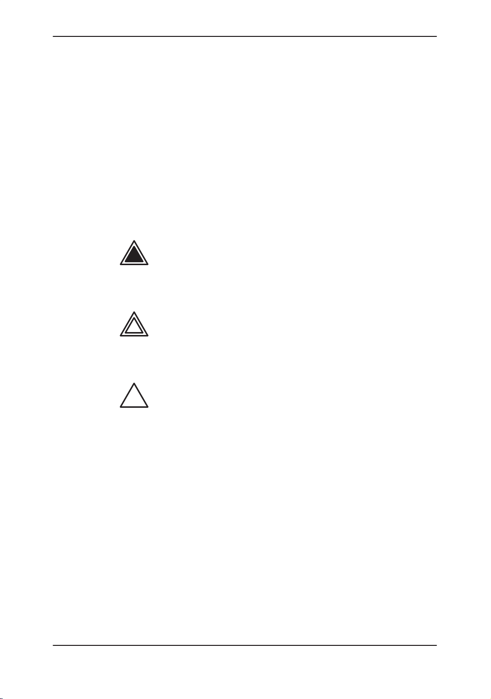
Icon Description
Safety Precautions
Various levels of safety precautions may be found on the
equipment and different levels of concern are identified by one
of the following flag words which precede the precautionary
statement.
DANGER
W ARNING
CAUTION
.
Indicates that a specific hazard is known to exist which through
inappropriate conditions or actions will cause:
S Severe or fatal personal injury
S Substantial property damage.
Indicates that a specific hazard is known to exist which through
inappropriate conditions or actions may cause:
S Severe personal injury
S Substantial property damage.
Indicates that a potential hazard may exist which through
inappropriate conditions or actions will or can cause:
S Minor injury
S Property damage.
Indicates precautions or prudent use recommendations that
should be used in the operation of the ultrasound system,
specifically:
S Use of the ultrasound system as a prescription device,
under the order of a physician
2–2
S Maintaining an optimum system environment
S Using this Manual
S Notes to emphasize or clarify a point.
LOGIQ 400 Basic Users Manual
2260260–100 Rev . 1
Page 35

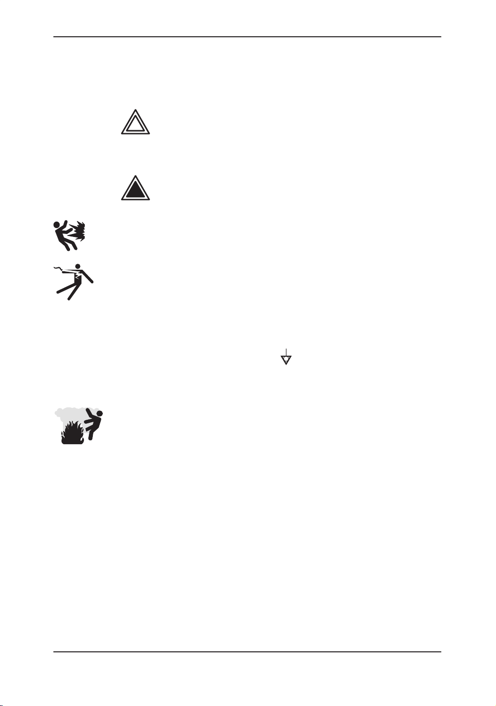
Hazard Symbols
Icon Description
Icon Potential Hazard Usage Source
Biological
Hazard
Electrical
Hazard
Moving
Hazard
Acoustic
Output
Hazard
Safety Precautions
Potential hazards are indicated by the following icons:
Patient/user infection due
to contaminated
equipment.
Electrical micro-shock to
patient, e.g., ventricular
fibrillation initiated.
Electrical micro-shock to
patient/user.
Console, accessories or
optional storage devices
fall on patient, user, or
others.
Collision with persons or
objects results in injury while
maneuvering or during
system transport.
Injury to user from moving
the console.
Patient injury or tissue
damage from ultrasound
radiation.
Cleaning and care
instructions
Sheath and glove
guidelines
Probes
ECG
Connections to back panel
Moving
Using brakes
Transporting
ALARA, the use of acoustic
output following the as low
s reasonably achievable
a
principle
ISO 7000
No. 0659
Explosion
Risk of explosion if used in
Hazard
Smoke
Patient/user injury or
& Fire
Hazard
Non–
Patient/user injury from
Console failure, erratic
Ionizing
Radiation
LOGIQ 400 Basic User Manual
2260260–100 Rev . 1
the presence of flammable
anesthetics.
adverse reaction from fire or
smoke.
explosion and fire.
operation or output error
due to RF interference.
Flammable anesthetic
Replacing fuses
Outlet guidelines
RF
Table 2–1. Potential Hazards
IEC 878
No. 03-04
2–3
Page 36

Safety Precautions
Important Safety Considerations
Patient Safety
Related Hazards
W ARNING
Patient
identification
Diagnostic
information
The following topic headings (
and Personnel Safety
user aware of particular hazards associated with the use of this
equipment and the extent to which injury can occur if
precautions are not observed. Additional precautions may be
provided throughout the manual. The equipment user is
obligated to be familiar with these concerns and avoid
conditions that could result in injury.
The concerns listed can seriously affect the safety of patients
undergoing a diagnostic ultrasound examination.
Always include proper identification with all patient data and
verify the accuracy of the patient’s name or ID numbers when
entering such data. Make sure correct patient ID is provided on
all recorded data and hard copy prints. Identification errors
could result in an incorrect diagnosis.
Equipment malfunction or incorrect settings can result in
measurement errors or failure to detect details within the image.
The equipment user must become thoroughly familiar with the
equipment operation in order to optimize its performance and
recognize possible malfunctions. Applications training is
available through the local GE representative. Added
confidence in the equipment operation can be gained by
establishing a quality assurance program.
) are intended to make the equipment
Patient Safety
, and
Equipment
2–4
Mechanical
hazards
Damaged probes or improper use and manipulation of
intracavitary probes can result in injury or increased risk of
infection. Inspect probes often for sharp, pointed, or rough
surface damage that could cause injury or tear protective
barriers. Never use excessive force when manipulating
intracavitary probes. Become familiar with all instructions and
precautions provided with special purpose probes.
LOGIQ 400 Basic Users Manual
2260260–100 Rev . 1
Page 37

Related Hazards (cont’d)
Safety Precautions
Electrical
Hazard
Acoustic
Output
Hazard
Training
A damaged probe can also increase the risk of electric shock if
conductive solutions come in contact with internal live parts.
Inspect probes often for cracks or openings in the housing and
holes in and around the acoustic lens or other damage that
could allow liquid entry. Become familiar with the probe’s use
and care precautions outlined in
Ultrasound energy, even at diagnostic levels, is capable of
damaging sensitive tissues if adequate precautions are not
followed. The wrong combination of equipment settings, probe
positioning, and tissue type can result in injury. Please become
thoroughly familiar with equipment controls that affect acoustic
output levels as well as the output display.
Follow the principle of a
(ALARA) when scanning a patient. During each ultrasound
examination, the clinical user is expected to weigh the medical
benefit of the diagnostic information obtained against the risk of
potential harmful effects. Once an optimal image is achieved
the need for increasing acoustic output or prolonging the
exposure cannot be justified.
It is recommended that all users receive proper training in
applications before performing them in a clinical setting. Please
contact the local GE representative for training assistance.
ALARA training is provided by GE Application Specialists.
s low as reasonably achievable
Probes and Biopsy
.
LOGIQ 400 Basic User Manual
2260260–100 Rev . 1
2–5
Page 38
Safety Precautions
Equipment and Personnel Safety
Related Hazards
WARNING
DANGER
Explosion
Electrical
Hazard
Hazard
This equipment contains dangerous voltages that are capable
of serious injury or death.
There are no user serviceable components inside the console.
Refer all servicing to qualified service personnel only.
The concerns listed below can seriously affect the safety of
equipment and personnel during a diagnostic ultrasound
examination.
Risk of explosion if used in the presence of flammable
anesthetics.
To avoid injury:
Do not remove protective covers. No user serviceable
parts are inside. Refer servicing to qualified service
personnel.
To assure adequate grounding, connect the attachment
plug to a reliable (hospital grade) grounding outlet (having
equalization conductor
Do not place liquids on or above the console. Spilled liquid
may contact live parts and increase the risk of shock.
).
2–6
Smoke
& Fire
Hazard
The system must be supplied from an adequately rated
electrical circuit. The capacity of the supply circuit must be as
specified on
3–4
.
LOGIQ 400 Basic Users Manual
2260260–100 Rev . 1
Page 39
Related Hazards (cont’d)
Safety Precautions
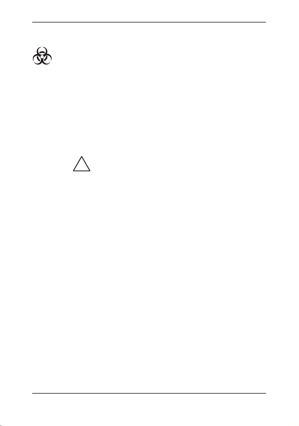
Biological
CAUTION
Hazard
For patient and personnel safety, beware of biological hazards
while performing invasive procedures. To avoid the risk of
disease transmission:
Use protective barriers (gloves and probe sheaths)
whenever possible. Follow sterile procedures when
appropriate.
Thoroughly clean probes and reusable accessories after
each patient examination and disinfect or sterilize as
needed. Refer to
care instructions.
Follow all infection control policies established by your
office, department or institution as they apply to personnel
and equipment.
Devices containing latex may cause severe allergic reaction in
latex sensitive individuals. USA customers should refer to the
FDA’s March 29, 1991 Medical Alert on latex products.
Probes and Biopsy
for probe use and
LOGIQ 400 Basic User Manual
2260260–100 Rev . 1
2–7
Page 40

Safety Precautions
Device Labels
Label Icon Description
The following table describes the purpose and location of safety
labels and other important information provided on the
equipment.
Label/Icon Purpose/Meaning Location
Identification and Rating
Plate
Type/Class Label Used to indicate the degree of safety or
IP Code (IPX1) Indicates the degree of protection provided by
Manufacturer’s name and address
Date of manufacture
Model and serial numbers
Electrical ratings (Volts, Amps, phase, and
frequency)
protection.
the enclosure per IEC 529. IPX1 indicates drip
proof.
Equipment Type BF (man in the box symbol)
IEC 878-02-03 indicates B Type equipment
having a floating applied part.
Rear of console near power
inlet
Foot Switch
Probe connectors and PCG
connector
0459
Device Listing/
Certification Labels
“DANGER – Risk of
explosion used in...”
Equipment Type CF (heart in the box symbol)
IEC 878-02-05 indicate equipment having a
floating applied part having a degree of
protection suitable for direct cardiac contact.
The CE Mark of Conformity indicates this
machine conforms with the Council Directive
93/42/EEC
Laboratory logo or labels denoting
conformance with industry safety standards
such as UL or IEC.
The system is not designed for use with
flammable anesthetic gases.
“CAUTION” The equilateral triangle is usually
used in combination with other symbols to
advise or warn the user.
Table 2–2. Label Icons
ECG connector and surgical
probes
Rear of console
Rear of console
Various
2–8
LOGIQ 400 Basic Users Manual
2260260–100 Rev . 1
Page 41
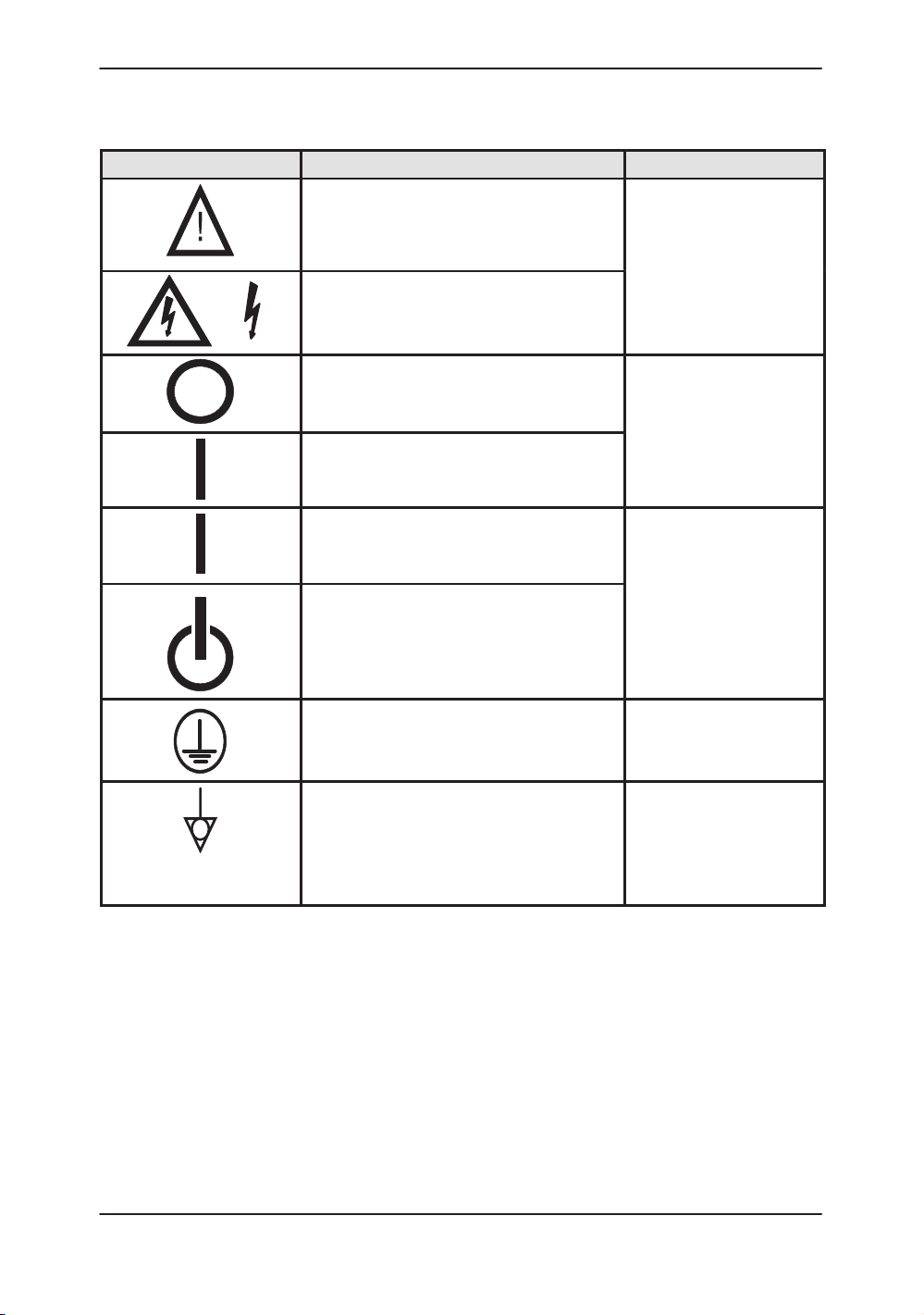
Label Icon Description (cont’d)
Label/Icon Purpose/Meaning Location
“ATTENTION – Consult accompanying
documents” is intended to alert the user to
refer to the operator manual or other
instructions when complete information cannot
be provided on the label.
“CAUTION – Dangerous voltage” (the lightning
flash with arrowhead) is used to indicate
electric shock hazards.
Safety Precautions
Various
“Mains OFF” Indicates the power off position of
the mains power switch.
“Mains ON” Indicates the power on position of
the mains power switch.
“ON” Indicates the power on position of the
power switch.
CAUTION: This Power Switch DOES NOT
ISOLATE Mains Supply.
“Off/Standby” Indicates the power off/standby
position of the power switch.
CAUTION: This Power Switch DOES NOT
ISOLATE Mains Supply.
“Protective Earth” Indicates the protective earth
(grounding) terminal.
“Equipotentiality” Indicates the terminal to be
used for connecting equipotential conductors
when interconnecting (grounding) with other
equipment.
CAUTION: This is only for ”FUNCTIONAL
GROUNDING”, NOT ”PROTECTIVE EARTH”.
Rear of system,
adjacent to mains switch
Adjacent to On-Off/Standby
Switch
Internal
Rear of console
Table 2–2. Label Icons (cont’d)
LOGIQ 400 Basic User Manual
2260260–100 Rev . 1
2–9
Page 42

Safety Precautions
Label Icon Description (cont’d)
Label/Icon Purpose/Meaning Location
Non–Ionizing Electromagnetic Radiation. Used
on the equipment to designate ISM Group 2 in
accordance with standard CISPR 11.
Rear of console
NRTL Listing and Certification Mark. Is used to
designate conformance to nationally
recognized product safety standards. The Mark
bears the name and/or logo of the testing
laboratory , product category, safety standard to
which conformity is assessed and a control
number.
Table 2–2. Label Icons (cont’d)
Rear of console
2–10
LOGIQ 400 Basic Users Manual
2260260–100 Rev . 1
Page 43

Classifications
*1. Class I EQUIPMENT
*2. Type BF EQUIPMENT
Safety Precautions
Type of protection against electric shock
Class I Equipment (*1)
Degree of protection against electric shock
Type BF Equipment (*2) (Except ECG)
Type CF Equipment (*3) (ECG Only)
Ordinary Equipment
Continuous Operation
EQUIPMENT in which protection against electric shock does
not rely on BASIC INSULATION only, but includes an earth
ground. This additional safety precaution prevents exposed
metal parts from becoming LIVE in the event of an insulation
failure.
TYPE B EQUIPMENT with an F-TYPE APPLIED P ART
TYPE B EQUIPMENT: EQUIPMENT providing a specified
degree of protection against electric shock, with particular
regard to allowable LEAKAGE CURRENT.
Patient leakage current
*3. Type CF EQUIPMENT
Patient leakage current
Normal Mode Single fault condition
Less than 100 mA Less than 500 mA
EQUIPMENT providing a degree of protection higher than that
for TYPE BF EQUIPMENT against electric shock particularly
regarding allowable LEAKAGE CURRENTS, and having an
F-TYPE APPLIED P ART.
Normal Mode Single fault condition
Less than 10 mA Less than 50 mA
LOGIQ 400 Basic User Manual
2260260–100 Rev . 1
2–11
Page 44

Safety Precautions
Classifications (cont’d)
*4. EMC (Electromagnetic Compatibility)
4.1 EMC Performance
All types of electronic equipment may characteristically cause
electromagnetic interference with other equipment, either
transmitted through air or connecting cables. The term EMC
(Electromagnetic Compatibility) indicates the capability of
equipment to curb electromagnetic influence from other
equipment and at the same time not affect other equipment with
similar electromagnetic radiation from itself.
This product is designed to fully comply with the EN60601–1–2
(IEC60601–1–2) in medical electric equipment EMC
regulations.
Proper installation following the service manual is required in
order to achieve the full EMC performance of the product.
The product must be installed as stipulated in 4.2, Notice upon
Installation of Product.
CAUTION
In case of issues related to EMC, please call your service
personnel.
Do not use the following devices near this equipment. Use of
these devices near this equipment could cause this equipment
to malfunction.
Devices which intrinsically transmit radio waves such as:
Cellular phone, radio transceiver, mobile radio transmitter,
radio-controlled toys, etc.
Keep power to these devices turned off when near this
equipment.
Medical staff in charge of this equipment is required to instruct
technicians, patients and other people who may be around this
equipment to fully comply with the above regulaion.
2–12
LOGIQ 400 Basic Users Manual
2260260–100 Rev . 1
Page 45

Classifications (cont’d)
4.2 Notice upon Installation of Product
Safety Precautions
1. Use either power supply cords provided by GE Medical
Systems or ones designated by GE Medical Systems.
Products equipped with a power source plug should be
plugged into the fixed power socket which has the
protective grounding conductor. Never use any adaptor
or converter to connect with a power source plug (i.e.
three-prong-to-two-prong converter).
2. Locate the equipment as far away as possible from
other electronic equipment.
3. Be sure to use only the cables provided by or
designated by GE Medical Systems. Connect these
cables following the installation procedures (i.e. wire
power cables separately from signal cables).
4. Lay out the main equipment and other peripherals
following the installation procedures described in the
Option Installation manuals.
4.3 General Notice
1. Designation of Peripheral Equipment Connectable to
This Product.
The equipment indicated on
the product without compromising its EMC
performance.
Avoid using equipment not designated in the list.
Failure to comply with this instruction may result in poor
EMC performance of the product.
13–5
can be hooked up to
LOGIQ 400 Basic User Manual
2260260–100 Rev . 1
2–13
Page 46

Safety Precautions
Classifications (cont’d)
4.3 General Notice (cont’d)
2. Notice against User Modification
The user should never modify this product. User
modifications may cause degradation in EMC
performance.
Modification of the product includes changes in:
a. Cables (length, material, wiring, etc.)
b. System installation/layout
c. System configuration/components
d. Securing system parts (cover open/close, cover
screwing)
3. Operate the system with all covers closed. If a cover is
opened for some reason, be sure to shut it before
starting/resuming operation.
Operating the system with any cover open may affect
EMC performance.
2–14
LOGIQ 400 Basic Users Manual
2260260–100 Rev . 1
Page 47
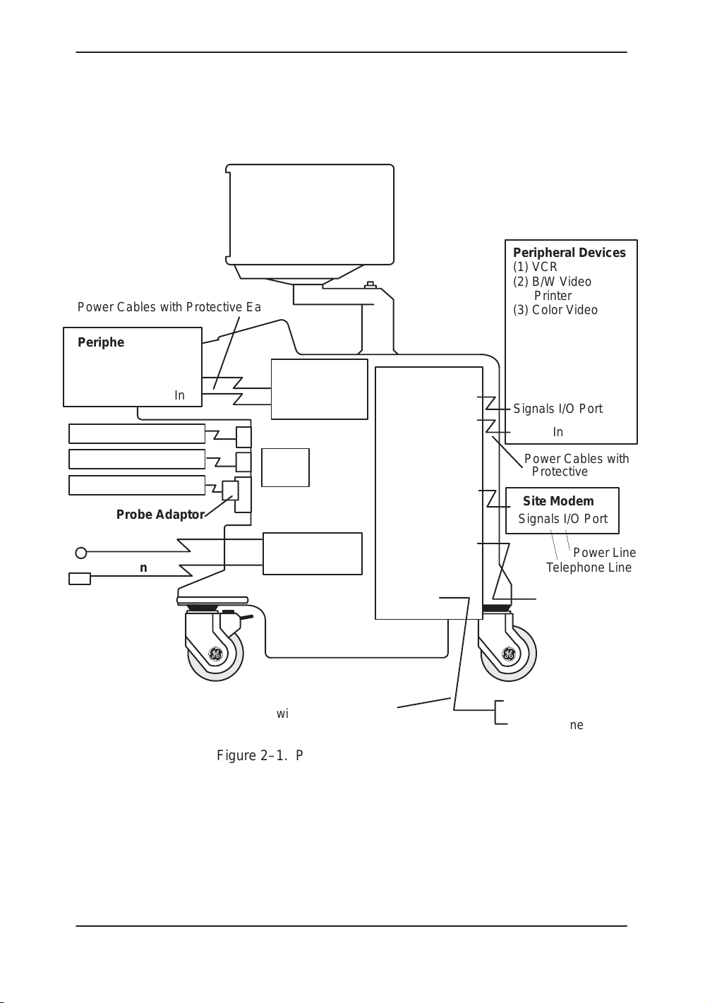
Classifications (cont’d)
*5. Patient Environmental Devices
Power Cables with Protective Earth
Peripheral Device
(1) B/W Video Printer
Signals I/O Port
Power In
Non–Imaging Probes
Signals I/O Port
Power Out
Front Panel
Rear Panel
Signals I/O Port
Power Out
Safety Precautions
Peripheral Devices
(1) VCR
(2) B/W Video
Printer
(3) Color Video
Printer
(4) B/W Polaroid
Camera
(5) Color Polaroid
Camera
Signals I/O Port
Power In
Imaging Probes
Imaging Probes
Probe Adaptor
ECG Cable
PCG Sensor
Probe
Ports
Signals I/O Port
Physio–Signal
Input Panel
Power Cable with Protective Earth
Foot Switch
Connector
Power In
Figure 2–1. Patient Environmental Devices
Power Cables with
Protective Earth
InSite Modem
Signals I/O Port
Power Line
Telephone Line
Foot Switch
Power Line (AC~)
Ground Line
LOGIQ 400 Basic User Manual
2260260–100 Rev . 1
2–15
Page 48

Safety Precautions
Classifications (cont’d)
5.1 Acceptable Devices
The devices shown in Figure 2–1 are specified to be suitable for
use within the PATIENT ENVIRONMENT.
CAUTION
CAUTION
DO NOT connect any probes or accessories without approval
by GE.
Please refer to Peripheral Devices on
16–39
and verified to be compatible with the LOGIQ 400 system.
5.2 Unapproved Devices
The user takes All Responsibility for connecting unapproved
devices.
If devices are connected without the approval of GE, the
warranty will be INVALID.
Any device connected to the LOGIQ 400 must conform to one
or more of the requirements listed below:
for more details. The devices listed have been tested
1. IEC 50, IEC 65, IEC 335, IEC 348, IEC 414, IEC 820,
IEC 950, IEC 1010–1, ISO 7767, ISO 8185, ISO 8359
or IEC 60601–1.
2. The devices shall be connected to PROTECTIVE
EARTH (GROUND).
13–5
and Assistance on
2–16
LOGIQ 400 Basic Users Manual
2260260–100 Rev . 1
Page 49

Acoustic Output
Controls Affecting Output
The potential for producing mechanical or thermal bioeffects is
influenced by the controls listed below (refer to
Direct. The Acoustic Output control has the most significant
effect on Acoustic Output.
Indirect. Indirect effects may occur when adjusting the controls
listed on
Always observe the output display for possible effects.
Best practices while scanning
2–18
Safety Precautions
2–18
).
.
Hints
.
WARNING
Acoustic
Output
Hazard
S Raise the Acoustic Output only after attempting image
optimization with controls that have no affect on Acoustic
Output, such as Gain and TGC.
NOTE: Refer to the Optimization sections of the Modes chapter
for a complete discussion of each control.
Be sure to have read and understood control explanations for
each Mode intended to be used before attempting to adjust the
Acoustic Output control or any control that can affect Acoustic
Output.
Use the minimum necessary output to get the best diagnostic
image or measurement during an examination. Begin the exam
with the probe that provides an optimum focal depth and
penetration.
LOGIQ 400 Basic User Manual
2260260–100 Rev . 1
2–17
Page 50

Safety Precautions
Best practices while scanning (cont’d)
Controls
Mode Control Affect Default Setting
All Acoustic Output Direct.
B Focus Comb Indirect. Minor Off.
B/M/CFD Depth
(FOV)
B/M Focal Zone Position
and Number
B/CFD Scan Area Indirect. Off.
Doppler M/D Cursor Indirect. Minor Of f.
Doppler Doppler Sample
Volume Gate Length
Doppler Velocity Scale Indirect. Minor Application-dependent operator preset.
PWD/CFD Freq. Hi/Low Indirect. Minor Low.
CFD Scan Area Indirect. Minor Off.
B/M/CFD Zoom Indirect. Minor Off.
Significant
Indirect. Minor Probe-dependent operator
Indirect. Minor Probe-dependent system
Indirect. Minor Application-dependent system preset.
The middle setting is a factory preset
determined to be a reasonable setting for all
exams. Use presets to set the output
preferred by scan mode and exam
combination.
preset.
preset.
Table 2–3. Controls Affecting Acoustic Output
Acoustic Output Default Levels
In order to assure that an exam does not start at a high output
level, the LOGIQ 400 initiates scanning at a reduced default
output level. This reduced level is preset programmable and
depends upon exam category, application preset and probe
selected. It takes effect when the system is powered on or New
Patient is selected.
2–18
LOGIQ 400 Basic Users Manual
2260260–100 Rev . 1
Page 51

Warning Label Locations
Overview
LOGIQ 400 warning labels are provided in seven different
languages (English, Japanese, German, French, Italian,
Portuguese, Spanish, Swedish, Danish, Russian, Greek and
Turkish).
Monitor Labels
A temporary label is placed on the monitor face to warn not to
move the monitor support arm without the monitor attached.
This label is removed after installation of the monitor.
Safety Precautions
Figure 2–2. Temporary Warning Label and Location
LOGIQ 400 Basic User Manual
2260260–100 Rev . 1
2–19
Page 52

Safety Precautions
Monitor Labels (cont’d)
Two caution labels are found on the back of the monitor. One
warns to only move the console with the monitor in its lowest
position; the second warns not to push the console from the
side.
12
2–20
Figure 2–3. Lowering Monitor Caution Labels and Locations
LOGIQ 400 Basic Users Manual
2260260–100 Rev . 1
Page 53

Monitor Labels (cont’d)
One caution label is found on the top of the monitor.
Safety Precautions
Figure 2–4. Top of Monitor Caution and Location
LOGIQ 400 Basic User Manual
2260260–100 Rev . 1
2–21
Page 54

Safety Precautions
Console Labels
Defibrillator Caution
Labels found on the back and side of the console will either be
translated to the twelve languages or be specific to the region.
2–22
Figure 2–5. Defibrillator Label Location
LOGIQ 400 Basic Users Manual
2260260–100 Rev . 1
Page 55

Ground Point
Safety Precautions
CAUTION
Figure 2–6. Signal Ground Point Location and Label
This is only for “FUNCTIONAL GROUNDING”, NOT
“PROTECTIVE EARTH”.
LOGIQ 400 Basic User Manual
2260260–100 Rev . 1
2–23
Page 56

Safety Precautions
Regulatory Labels (European Systems)
2–24
Figure 2–7. Regulatory Label Location (European)
LOGIQ 400 Basic Users Manual
2260260–100 Rev . 1
Page 57

Regulatory Labels (European Systems) (cont’d)
Safety Precautions
Figure 2–8. Regulatory Label Location (European) (cont’d)
LOGIQ 400 Basic User Manual
2260260–100 Rev . 1
2–25
Page 58

Safety Precautions
Regulatory Labels (American Systems)
2–26
Figure 2–9. Regulatory Label Location (Americas)
LOGIQ 400 Basic Users Manual
2260260–100 Rev . 1
Page 59

Introduction
Site Requirements
Site Requirements
Only qualified physicians or sonographers should perform
ultrasound scanning on human subjects for medical diagnostic
reasons. Request training, if needed.
Do not attempt to install the system alone. General Electric,
Affiliate, or Distributor Field Engineers and Application
Specialists will install and setup the system. Refer to Who To
Contact on
The LOGIQ 400 does not contain any operator serviceable
internal components. Ensure that unauthorized personnel do
not tamper with the unit.
Perform regular preventive maintenance. Refer to
maintenance instructions.
Maintain a clean environment. Turn off the system circuit
breaker before cleaning the unit. Refer to
instructions.
Never set liquids on the unit to ensure that liquid does not drip
into the control panel or unit.
1–8
.
16–11
for
16–12
for cleaning
LOGIQ 400 Basic User Manual
2260260–100 Rev . 1
3–3
Page 60

Site Requirements
Before the system arrives
NOTICE This medical equipment is approved, in terms of the prevention
of radio wave interference, to be used in hospitals, clinics and
other institutions which are environmentally qualified. The use
of this equipment in an inappropriate environment may cause
some electronic interference to radios and televisions around
the equipment. This equipment can be used in residential
areas only under the supervision of physicians or qualified
technicians.
Ensure that the following is provided for the new system:
A separate power outlet with a 15 amp circuit breaker for
120 VAC (USA) or 7.5 amp circuit breaker for 220–240 VAC
(Europe, Latin America).
Take precautions to ensure that the console is protected
from electromagnetic interference.
Precautions include:
Operate the console at least 15 feet away from motors,
typewriters, elevators, and other sources of strong
electromagnetic radiation.
Operation in an enclosed area (wood, plaster or
concrete walls, floors and ceilings) helps prevent
electromagnetic interference.
Special shielding may be required if the console is to be
operated in the vicinity of radio broadcast equipment.
3–4
LOGIQ 400 Basic Users Manual
2260260–100 Rev . 1
Page 61

Environmental Requirements
The system should be operated, stored, or transported within
the parameters outlined below. Either its operational
environment must be constantly maintained or the unit must be
turned off.
Operational Storage Transport (<16 hrs.)
Temperature
Humidity
Pressure
Table 3–1. System Environmental Requirements
10- 40 C
50- 104 F
30-85%
non-condensing
700-1060hPa 700-1060hPa 700-1060hPa
–10- 60 C
14- 140 F
30-90%
non-condensing
Site Requirements
–40- 60 C
–40- 140 F
30-90%
non-condensing
LOGIQ 400 Basic User Manual
2260260–100 Rev . 1
3–5
Page 62

Console Overview
Console graphics
Console Overview
The following are illustrations of the console:
2
1
1 Monitor
2 Optional Probe Cable Holder (wire holder standard for Americas’ systems)
3 Probe and Gel Bottle Holder (Removable for Cleaning)
4 Optional Cable Clipper for Probe Cable
Figure 3–1. LOGIQ 400 System (right and left side views)
3
4
1
3–6
LOGIQ 400 Basic Users Manual
2260260–100 Rev . 1
Page 63

Console graphics (cont’d)
Console Overview
14
1
2
3
4
7
8
9
10
7
11
1
!
ECG
5
PCG
6
1 Monitor
2 Task Light Switch
3 Task Light
4 Optional B/W Video Page Printer
5 Air Filter (front and back of system)
6 Power Supply Air Filter
7 Optional Probe Cable Holder (wire holder standard for Americas’ systems)
8 VCR Microphone
9 Release Button—to raise and lower video monitor
10 Optional Physiological Input Panel
11 Swivel Lock on Video Monitor Arm
12 Peripheral Cable Access Panel Door
13 Cable Access Channel
14 Optional Third Probe Port
Aux
12
13
5
ON
ON
OFF10
Figure 3–2. LOGIQ 400 System (front and back views)
LOGIQ 400 Basic User Manual
2260260–100 Rev . 1
3–7
Page 64

Console Overview
External disk drive
Storage areas
The external MOD drive is a 3.5 inch 128MB/230MB MOD drive
located below the keyboard.
It can be used to perform software upgrades, image archiving
(option) and service diagnostics.
Several convenient storage areas are provided within the
console as shown by the shaded areas in Figure 3–3. Use
them to store gel, options, probe cables, accessories, etc.
1
3–8
1
1 Storage
Figure 3–3. Storage Areas
LOGIQ 400 Basic Users Manual
2260260–100 Rev . 1
Page 65

Peripheral/Accessory Connection
Peripheral/Accessory Connector Panel
LOGIQ 400 peripherals and accessories can be properly
connected using the rear connector panel located behind the
rear door. Only the B/W Page Printer (UP-890) can be
connected to the front accessory panel.
Located on the rear panel are video input and output, audio
input and output, camera expose, foot switch, power and
control connections for VCR, printer, MIC and service tools.
See Figure 3–5.
Console Overview
CAUTION
CAUTION
Each outer (case) ground line of peripheral/accessory
connectors are Earth Grounded.
Signal ground lines are Not Isolated, except the Service Port.
All of the signal lines (including the signal ground) of the
Service Port are Isolated.
Service
Figure 3–4. Service Port
Use only approved probes, peripherals or accessories.
LOGIQ 400 Basic User Manual
2260260–100 Rev . 1
3–9
Page 66

Console Overview
Peripheral/Accessory Connector Panel (cont’d)
100V 2.5A Max.
Includes front printer panel
120V 2.0A Max.
Includes front printer panel
220–240V 1.0A Max.
Includes front printer panel
12
1 Old Rear Panel 2 New Rear Panel
Figure 3–5. Peripheral/Accessory Connector Panel
3–10
LOGIQ 400 Basic Users Manual
2260260–100 Rev . 1
Page 67

Foot Switch (option)
Console Overview
Freeze
Record
Foot Switch
Use only the recommended optional multi-functional Foot Switch
in parallel with or as an alternative to the Freeze and Record 1
controls to:
Freeze a real-time image (left switch).
Send an image to the hard copy device (right switch).
The Foot Switch connection is located at the back of the
console on the left-hand side of the back panel.
1
2
3
1 Accessory Panel for Foot Switch Connector
2 Store Foot Switch Here
3 Console Air Filter Screen
Figure 3–6. Foot Switch Storage and Connectors
Other Peripherals/Accessories (options)
Refer to
more information.
Chapter 13 (Recording Images)
ON
ON
OFF10
of this manual for
LOGIQ 400 Basic User Manual
2260260–100 Rev . 1
3–11
Page 68

System Positioning/Transporting
System Positioning/Transporting
Moving the System
When moving or transporting the system, follow the precautions
below to ensure the maximum safety for personnel, the system,
and other equipment.
Before moving the system:
1. Turn the system power switch off.
2. Unplug the power cord.
3. All cables from off-board peripheral devices (IIE
camera, external printer, VCR, etc.) must be
disconnected from the console.
4. Ensure that no loose items are left on the console.
5. Loop the cord around the handle on the back of the
system or wrap the cord in a bundle and store it behind
the rear storage panel.
To prevent damage to the Power Cord, DO NOT pull
excessively on the cord or make sharp bends while wrapping.
3–12
LOGIQ 400 Basic Users Manual
2260260–100 Rev . 1
Page 69
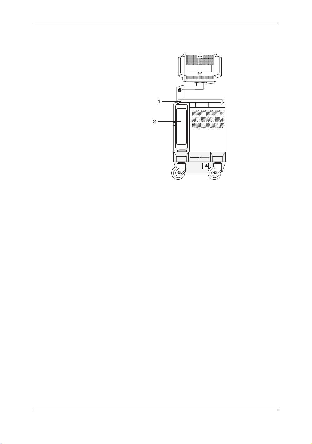
Moving the System (cont’d)
System Positioning/Transporting
ON
ON
OFF10
1 Handle
2 Storage Area Behind Door
Figure 3–7. Location of Storage Area
6. Connect all probes to be used while off site. Ensure
that probe cables are out of the way from the wheels
and not protruding beyond the console.
NOTE: Store all probes that are intended to be used, but not
connected to the system, securely in the front storage
area.
7. Store all other probes in their original cases or in soft
cloth or foam to prevent damage.
8. Store sufficient gel, optical disks, and other essential
accessories in the provided space.
9. Adjust the monitor to its lowest position possible.
Ensure that the monitor arm is locked in place.
10. Unlock the front wheels.
LOGIQ 400 Basic User Manual
2260260–100 Rev . 1
3–13
Page 70

System Positioning/Transporting
Moving the System (cont’d)
When moving the system:
1. Always use the rear handle grips to move the system.
2. Take extra care when moving the system long
distances and on inclines. Ask for help if necessary.
Avoid ramps that are steeper than ten degrees to avoid
tipping over the
system.
.
.
CAUTION
NOTE: Wheel chair ramps are usually less than five degrees.
Utilize additional care and personnel when moving on
steep incline (>5°) or loading into a vehicle for
transport.
NOTE: DO NOT attempt to move the console using any cables
or fixtures, such as the probe connectors.
3. Use the brake, located on the bottom of the system in
the front, when necessary.
4. Do not let the system strike walls or door frames.
5. Use extra care when crossing door or elevator
thresholds.
6. Once the destination is reached, lock the wheels.
The system weighs approximately 145 kg (320 lbs). To avoid
possible injury and equipment damage:
S Be sure the pathway is clear.
S Limit movement to a slow careful walk.
S Use two or more persons to move the system on inclines or
long distances.
3–14
LOGIQ 400 Basic Users Manual
2260260–100 Rev . 1
Page 71

Transporting the System
Use extra care when transporting the system using vehicles. In
addition to the instructions used when moving the system (refer
to
3–12
1. Only use vehicles that are designed for transport of the
2. Load and unload the system to a vehicle parked on a
3. Ensure that the transporting vehicle can handle the
4. Ensure that the load capacity of the lift (a minimum of
5. Ensure that the lift is in good working order.
6. Secure the system while it is on the lift so that it cannot
System Positioning/Transporting
), do the following:
LOGIQ 400 system.
level surface.
weight of the system plus the passengers.
180 kg [397 lbs] is recommended) is capable of
handling the weight of the system.
roll. Use either wood chocks, restraining straps, or
other similar types of constraints. Do not attempt to
hold it in place by hand.
WARNING
NOTE: Strap the system below its handle so that the system
does not break loose.
Never ride on the lift with the system. A person’s
weight coupled with the weight of the system may
exceed the load capacity of the lift.
7. Employ 2 to 3 persons to load and unload safely from a
vehicle.
8. Load the unit aboard the vehicle carefully and over its
center of gravity. Keep the unit still and upright.
NOTE: Do not lay the unit down.
9. Ensure that the system is firmly secured while inside
the vehicle. Any movement, coupled with the weight of
the system, could cause it to break loose.
10. Secure system with straps or as directed otherwise to
prevent motion during transport.
11. Prevent vibration damage by driving cautiously. Avoid
unpaved roads, excessive speeds, and erratic stops or
starts.
LOGIQ 400 Basic User Manual
2260260–100 Rev . 1
3–15
Page 72

System Positioning/Transporting
Wheels
Front wheels
Back wheels
Setting the lock
Examine the wheels frequently for any obvious defects that
could cause them to break or bind.
The front wheels swivel, pivot, and lock.
The back wheels swivel and pivot but do not lock.
NOTE: For the USA version console, the back wheels do not
pivot.
To engage the wheel lock:
Press down on the lock pedal (located at the front of
the wheels). The pedal remains depressed.
To release the lock:
Press down on the pedal again. The pedal returns to
its normal position.
3–16
LOGIQ 400 Basic Users Manual
2260260–100 Rev . 1
Page 73

Powering On the System
Connecting and Using the System
To connect the system to the electrical supply:
1. Ensure that the wall outlet is of the appropriate type.
2. Ensure that the power switch is turned off.
3. Unwrap the power cable. Make sure to allow sufficient
slack in the cable so that the plug is not pulled out of
the wall if the system is moved slightly.
4. Push the power plug securely into the wall outlet.
Powering On the System
W ARNING
Plug and Outlet Configuration
To avoid risk of fire, the system power must be supplied from a
separate, properly rated outlet. See
the system arrives
Under no circumstances should the AC power plug be altered,
changed, or adapted to a configuration rated less than
specified. Never use an extension cord or adapter plug.
To help assure grounding reliability, connect to a “hospital
grade” or “hospital only” grounded power outlet.
on
3–4
for rating information.
120 VAC, 1000 VA
(USA)
Figure 3–8. Example Plug and Outlet Configurations
220–240 VAC, 1000 VA
Plug and Outlet Configuration
Site Requirements, Before
(Europe)
LOGIQ 400 Basic User Manual
2260260–100 Rev . 1
3–17
Page 74

Powering On the System
Acclimation Time
After being transported, the unit requires one hour for each 2.5
increment its temperature is below 10 C or above 40 C.
C
F
hours
C
F
hours
60 55 50 45 40 35 30 25 20 15 10
140 131 122 113 104 95 86 77 68 59 50
8 6 4 2 0 0 0 0 0 0 0
5 0 –5 –10 –15 –20 –25 –30 –35 –40
41 32 23 14 5 –4 –13 –22 –31 –40
2 4 6 8 10 12 14 16 18 20
Table 3–2. System Acclimation Time Chart
Power On/Off Standby
CAUTION
Press the top portion of the Power On/Off Standby switch to
turn the power on. The circuit breaker, on the rear of the unit,
must also be in the on position (see
3–23
).
3–18
Figure 3–9. Power Switch Location
LOGIQ 400 Basic Users Manual
2260260–100 Rev . 1
Page 75

Power Up Sequence
Start of
diagnostic
run
1
Powering On the System
The monitor and console power indicator light up.
The system is initialized. During this time:
Two beeps sound during the sequence.
All lighted buttons on the keyboard light.
System diagnostics run. Its status is reflected on the
monitor by the graphics in
4
Figure 3–10
4
.
XXXXXXX–X
4
2
Version X.XX
4
Version X.XX
1 Current OBC Assembly Part Number 2 Current Software Version
Figure 3–10. Power Up Graphic Sequence
XXXXXXX–X
4
Version X.XX
End of
diagnostic
run
LOGIQ 400 Basic User Manual
2260260–100 Rev . 1
3–19
Page 76

Powering On the System
Power Up Sequence (cont’d)
.
Hints
.
Password Protection
NOTE: If errors occur, an error message appears at the bottom
of the screen. See User Maintenance, Troubleshooting
for more information.
If problems occur, freeze the image and take a picture
for reference. This will help if there is a need to call for
service.
S Probes are initialized for immediate operation.
NOTE: If no probes are connected, the system goes into
standby mode.
S Peripheral devices are activated on power up.
After initialization has been completed, the new patient entry
menu will be displayed.
A maximum of 8 personal IDs and associated passwords can
be preset in the LOGIQ 400 (see
If IDs and passwords have been entered and the Password Ask
parameter is on, the following occurs in the power up sequence:
S The message USERID:__________ appears in the middle
of the start up sequence.
14–60
).
3–20
S Type in a User ID and press Return.
S Keyboard lights go out.
S The message PASSWORD:__________ is highlighted.
S Type in the password that corresponds to the User ID and
press Return.
LOGIQ 400 Basic Users Manual
2260260–100 Rev . 1
Page 77

Password Protection (cont’d)
USER ID :
PASSWORD:
Figure 3–11. System Startup Screen with Password Ask on
If the correct User ID/Password is entered, the system
continues with the power up sequence.
Powering On the System
4
Version X.XX
If an incorrect User ID/Password is entered, the system allows
four additional attempts. After the fifth incorrect entry, the
message “Login incorrect” appears. The power up sequence
will not continue. The system must be turned off, then on, to
begin again.
NOTE: If User ID/Passwords are registered and the Password
Ask function is off, press Return at the ID__________ prompt.
The system continues the power up sequence.
LOGIQ 400 Basic User Manual
2260260–100 Rev . 1
3–21
Page 78

Powering On the System
Power Off
When switching off the system:
Move the ON, OFF/STAND-BY switch to the OFF position.
The message “WARNING: NOW STARTING THE POWER
OFF PROCESS” appears at the bottom of the display.
The LOGIQ 400 takes a few seconds to save current
scan parameter data in the temporary files to the hard drive
before turning the power off.
During this time a message flashes on the screen:
“Do not pull Power Cable.
Do not turn off Breaker.”
Pulling the power cable or turning off the circuit breaker,
while the hard drive is working, may corrupt the system
operating software on the hard drive.
If the system has not turned off five minutes after pressing
the power switch off, listen for hard drive activity. If there is
no hard disk drive activity, the circuit breaker on the bottom
of the power supply can be used to turn off the system. Do
NOT turn off the circuit breaker while the hard disk is
working.
Disconnect the probes.
Clean or sanitize all probes as necessary. Store them in
their shipping cases to avoid damage.
If daily maintenance is to be performed, turn off the circuit
breaker in the back of the system.
3–22
LOGIQ 400 Basic Users Manual
2260260–100 Rev . 1
Page 79
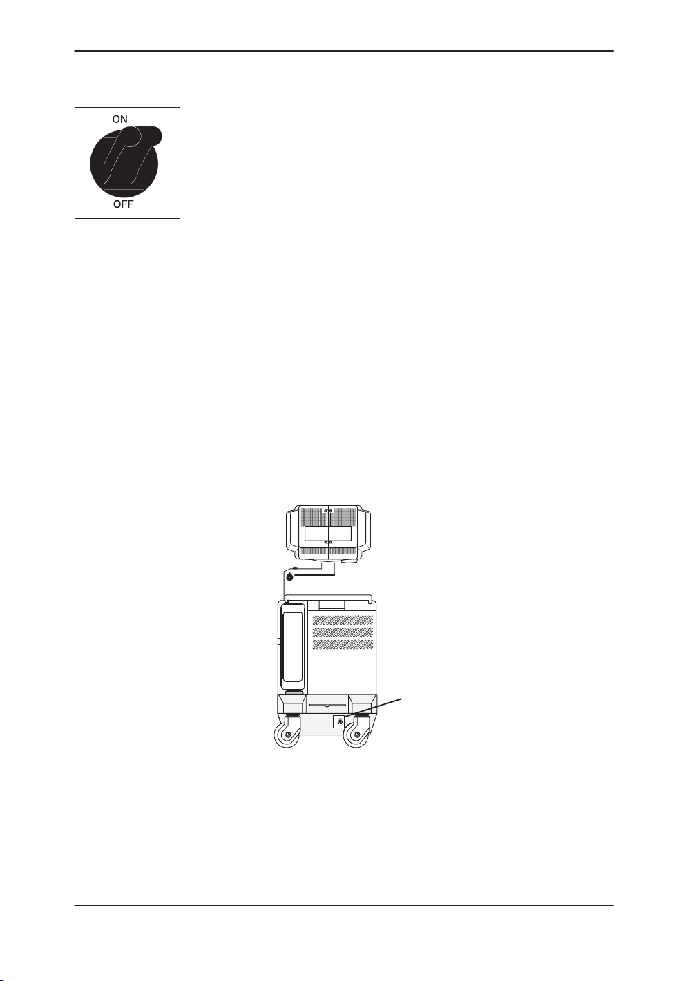
Circuit breaker
Powering On the System
1
0
The Circuit Breaker is located on the back of the console, at the
bottom of the system. On supplies main power to all internal
systems. Off removes main power from all internal systems.
The circuit breaker automatically shuts off power to the system
in case of a power overload.
If a power overload occurs:
1. Turn off all peripheral devices.
2. Turn off the Main Power Switch to the console.
3. Reactivate the Circuit Breaker switch.
The Circuit Breaker switch should stay in the On position; DO
NOT hold the switch in the On position. If the Circuit Breaker
switch remains On, follow the
described.
NOTE: If the Circuit Breaker switch does not remain in the On
position or trips again:
1. Disconnect the Power Cable.
2. Call Service immediately.
DO NOT attempt to use the system.
Power On
procedure previously
Figure 3–12. Location of Circuit Breaker
LOGIQ 400 Basic User Manual
2260260–100 Rev . 1
ON
ON
OFF10
1 Circuit Breaker
1
3–23
Page 80
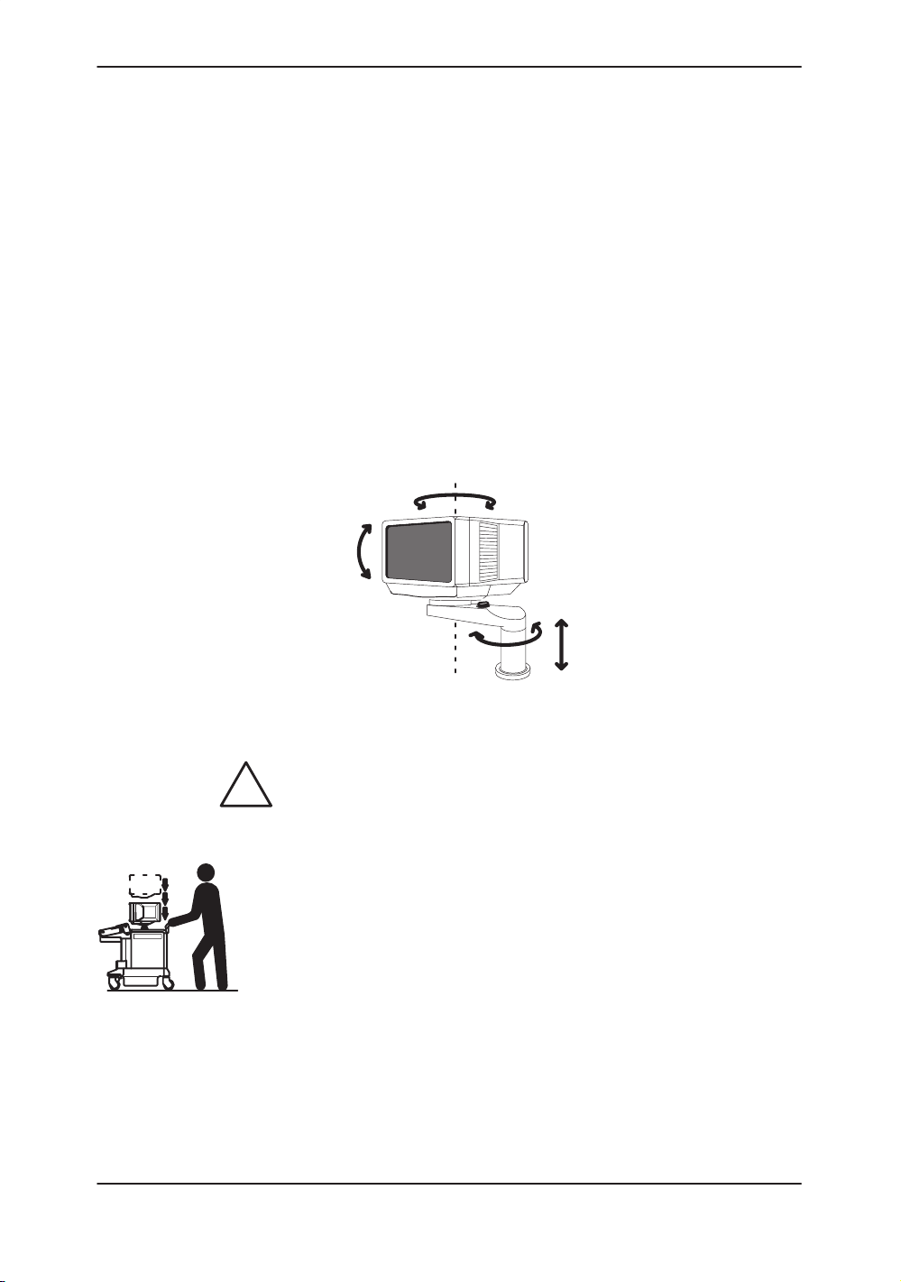
Adjusting the Monitor
Adjusting the Display Monitor
Rotate, tilt, raise and lower the monitor
The monitor position can be adjusted for easy viewing.
The monitor can be rotated around it’s central pivot point.
The monitor can be tilted for the optimum viewing angle.
The monitor arm can swing forward or backwards.
The monitor arm can be raised or lowered for the best
viewing height.
CAUTION
3–24
Figure 3–13. Display Monitor Movement
Movement of the monitor swing arm or height adjustment
requires the release of the locking mechanism. After an
adjustment is made, ensure that the mechanism is locked to
prevent unexpected motion.
When moving the LOGIQ 400 system, lower the monitor to its
lowest possible position to improve stability.
LOGIQ 400 Basic Users Manual
2260260–100 Rev . 1
Page 81

Brightness and Contrast
Adjusting the monitor’s contrast and brightness is one of the
most important factors for proper image quality. If these
controls are set incorrectly, the Gain, TGC, Dynamic Range and
even Acoustic Output may have to be changed more often than
necessary to compensate.
The proper setup displays a complete gray scale. The lowest
level of black should just disappear into the background and the
highest white should be bright, but not saturated.
To adjust the Brightness and Contast:
1. Press the monitor’s toggle button for brightness and
2. Adjust the brightness (or contrast) by pressing the
3. Select the Set Up Top Menu. From the Set Up
Adjusting the Monitor
contrast. Confirm that the brightness (or contrast) is
displayed on the monitor. If the contrast is displayed,
press the toggle button again.
AA (–) or "" (+) monitor’s adjustment buttons.
Sub-Menus, select Utility. The Utility Menu appears as
shown in Figure 3–14.
LOGIQ 400 Basic User Manual
2260260–100 Rev . 1
Figure 3–14. Utility Menu
3–25
Page 82

Adjusting the Monitor
Brightness and Contrast (cont’d)
4. Enter menu number “11” (Monitor Adjustment) in the
Utility Menu and press Return. The Monitor Adjustment
Menu appears as shown in Figure 3–15.
Figure 3–15. Monitor Adjustment Menu
5. Enter the number of a gray scale map for adjustment
according to the brightness of the exam room and the
exam category and press Return.
1: Dark Room—for a dimly lit room with a color
monitor.
2: Bright Room—for a well lit room with a color
monitor.
3: Cardiac—for a Cardiac Exam with a color monitor.
4: Dark Room (B/W)—for a dimly lit room with a black
and white monitor.
5: Bright Room (B/W)—for a well lit room with a black
and white monitor.
6: Cardiac (B/W)—for a Cardiac Exam with a black
and white monitor.
3–26
LOGIQ 400 Basic Users Manual
2260260–100 Rev . 1
Page 83

Brightness and Contrast (cont’d)
The adjustment maps’ gray scale bar appears on the
monitor as shown in Figure 3–16.
Gray Scale Bar
Adjusting the Monitor
1 Task Light Switch 4 Brightness/Contrast Adjustment (+) Button
2 Brightness/Contrast Toggle Button 5 Microphone
3 Brightness/Contrast Adjustment (–) Button
Figure 3–16. Brightness and Contrast
6. Press the "" (+) monitor adjustment button to the
maximum for brightness. Toggle to contrast. Press the
"" (+) monitor adjustment button to the maximum for
contrast. Toggle to brightness.
7. Decrease the brightness by degrees by pressing the
AA (–) monitor adjustment button until “B” in the gray
scale bar is not visible. Toggle to contrast.
8. Decrease the contrast by degrees by pressing the AA
(–) monitor adjustment button until “A” in the gray scale
bar is not visible.
9. Press the "" (+) monitor adjustment button to the
maximum for brightness again.
10. Decrease the brightness by degrees by pressing the
AA (–) monitor adjustment button until “C” in the gray
scale bar is not visible.
12
3 4 5
11. Press the Utility up/down arrow keys to return to the
LOGIQ 400 Basic User Manual
2260260–100 Rev . 1
previous scan mode.
3–27
Page 84

Adjusting the Monitor
Brightness and Contrast (cont’d)
Generally speaking, do not change the controls once they have
been set. Once set, the display then becomes the reference for
the hard copy device(s).
.
Manual Degauss
.
NOTE: After readjusting the monitor’s Contrast and Brightness,
readjust all preset and peripheral settings.
Degaussing refers to the process of removing magnetic-field
effects from the monitor. Operation of the monitor within a
magnetic field may adversely effect color purity. Degaussing
can be used to correct this problem. The monitor automatically
degausses at power on.
To activate the manual degauss:
1. Press the AA (–) or "" (+) monitor adjustment
buttons while the brightness/contrast adjustment
indicator is not displayed on the monitor. To cancel the
manual degauss, press the AA (–) or "" (+)
adjustment button again.
2. Press the toggle button for brightness and contrast.
3. Press the AA (–) or "" (+) Adjustment button.
NOTE: Monitor degaussing (demagnetizing) is done
automatically when the system is turned on.
3–28
LOGIQ 400 Basic Users Manual
2260260–100 Rev . 1
Page 85
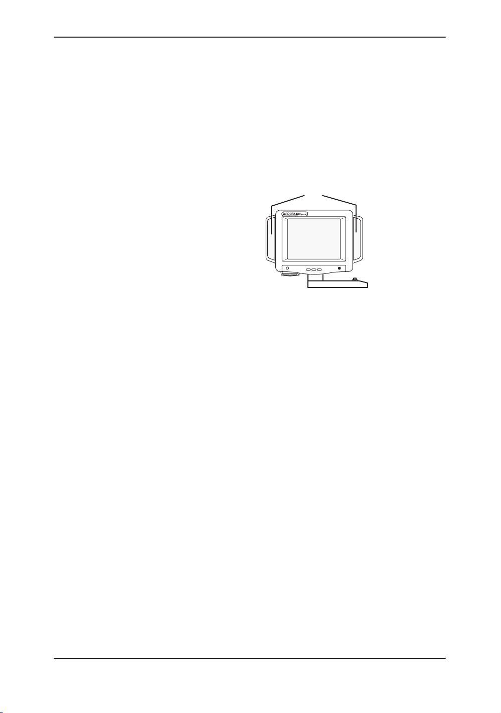
Speakers
Adjusting the Monitor
Stereo audio, provided by speakers located on the sides of the
Display Monitor, is standard for:
Audio Doppler operation (left side is blood flow away/right
side is blood flow toward)
Audio playback of videotaped scan sessions
Audio error notification
1
23
1 Speakers
2 Toward
3 Away
Figure 3–17. Display Monitor Speakers
LOGIQ 400 Basic User Manual
2260260–100 Rev . 1
3–29
Page 86

Probes
Introduction
Probes
Only use approved probes.
All imaging probes can be plugged into any of the two probe
ports. Third probe port is optional.
For more
information
Refer to the
Selecting a probe
Hints
S Always start out with a probe that provides optimum focal
S Begin the scan session using the default Acoustic Output
NOTE: Selecting a new probe unfreezes the image.
.
Connecting the Probe
Probes can be connected at any time, regardless of whether
the console is powered on or off. To ensure that the ports are
not active, place the system in the image freeze condition.
To connect a probe:
Probes
depths and penetration for the patient size and application.
setting for the probe and application.
1. Place the probe’s carrying case on a stable surface and
open the case.
2. Carefully remove the probe and unwrap the probe cord.
chapter.
CAUTION
3–30
3. DO NOT allow the probe head to hang free. Impact to
the probe head could result in irreparable damage.
4. Turn the connector locking handle counterclockwise.
5. Align the connector with the probe port and carefully
push into place.
LOGIQ 400 Basic Users Manual
2260260–100 Rev . 1
Page 87

Connecting the Probe (cont’d)
Figure 3–18. Probe Connector Panel
6. Turn the connector locking handle clockwise to secure
the probe connector.
7. Carefully position the probe cord so it is free to move
and is not resting on the floor.
Probes
23
Figure 3–19. Connecting a Probe
LOGIQ 400 Basic User Manual
2260260–100 Rev . 1
lock
unlock
3–31
Page 88

Probes
Cable Handling
Take the following precautions with probe cables:
Keep free from wheels
Do not bend the cable acutely
Avoid crossing cables between probes.
Activating the Probe
To activate the probe, press the Probe Select key that
corresponds to the probe port to which the desired probe is
connected. The Single CWD key is used to activate the
dedicated continuous wave Doppler (CWD) probe.
Figure 3–20. Probe Select Keys
The probe activates in the currently selected operating mode.
The probe’s default settings for the mode and selected
application are used automatically.
3–32
LOGIQ 400 Basic Users Manual
2260260–100 Rev . 1
Page 89
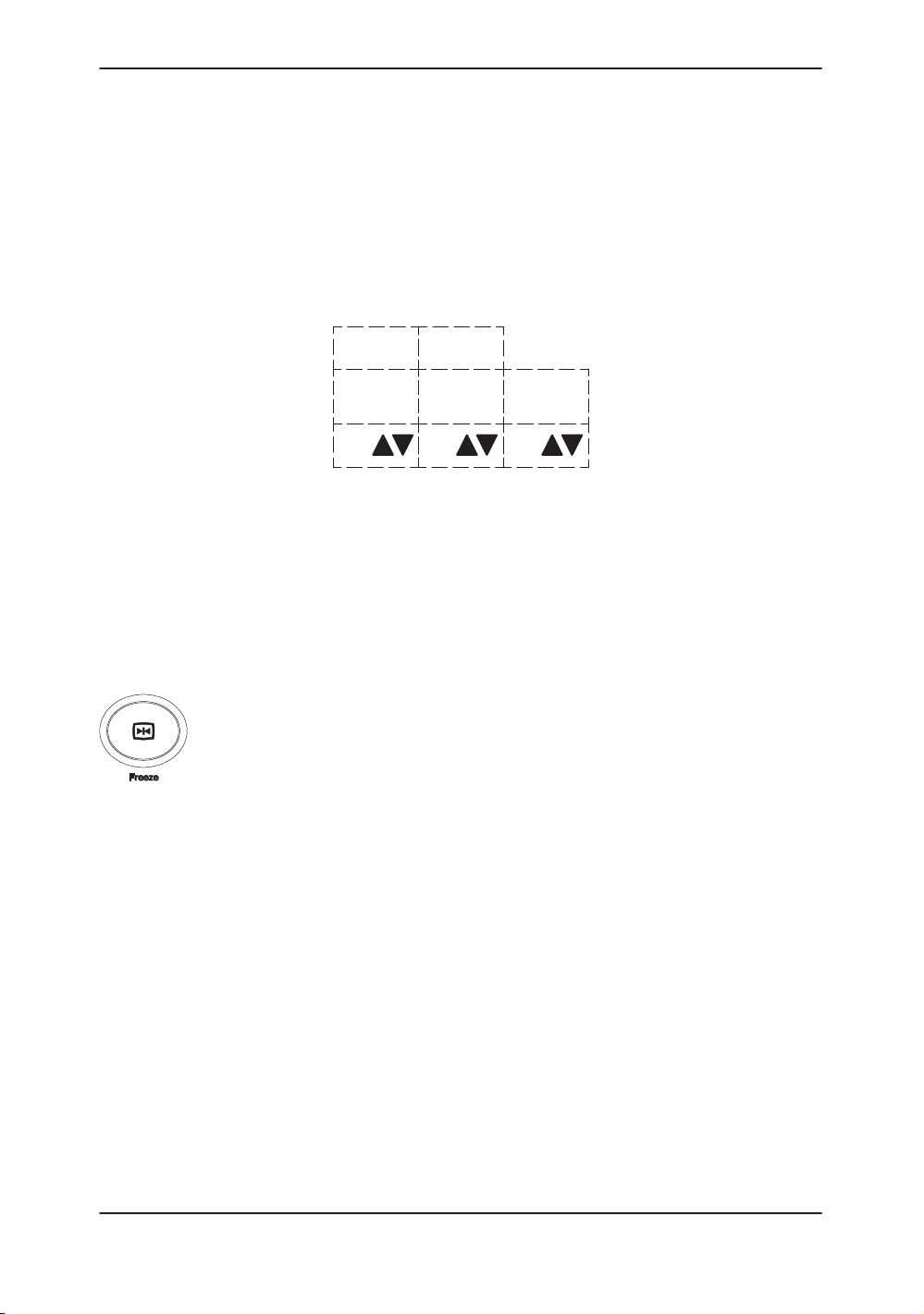
Probe Name Menu
Probes
If the Display Probe Name preset in the Setup/System
Parameters page one is ON, a list of names for the probes that
are attached to the system can be displayed by pressing the
Probe Select key once. The desired probe can then be
selected from the soft menu or by pressing the Probe Select
key until the desired probe LED is lit. Press the Mode Top
Menu key to exit the probe name display.
1/1B
Deactivating the Probe
When deactivating the probe, the probe is automatically placed
in standby mode.
To deactivate a probe:
Press the Freeze key.
Gently wipe the excess gel from the face of the probe.
Carefully slide the probe around the right side of the
Ensure that the probe is placed gently in the probe holder.
????
(1)
739L
(2)
C551
(3)
Figure 3–21. Probe Name Menu
keyboard, toward the probe holder.
LOGIQ 400 Basic User Manual
2260260–100 Rev . 1
3–33
Page 90

Probes
Disconnecting the Probe
Probes can be disconnected at any time. However, the probe
should not be selected as the active probe.
Move the probe locking handle counterclockwise.
Pull the probe and connector straight out of the probe port.
Carefully slide the probe and connector away from the
probe port and around the right side of the keyboard.
Ensure the cable is free.
Be sure that the probe head is clean before placing the
probe in its storage box.
Transporting Probes
Secure the probe in its holder for moving short distances.
When transporting a probe a long distance, store it in its
carrying case.
Storing the Probe
It is recommended that all probes be stored in the carrying case
provided.
First place the probe connector into the carrying case.
Carefully wind the cable into the carrying case.
Carefully place the probe head into the carrying case. DO
NOT use excessive force or impact the probe head.
3–34
LOGIQ 400 Basic Users Manual
2260260–100 Rev . 1
Page 91
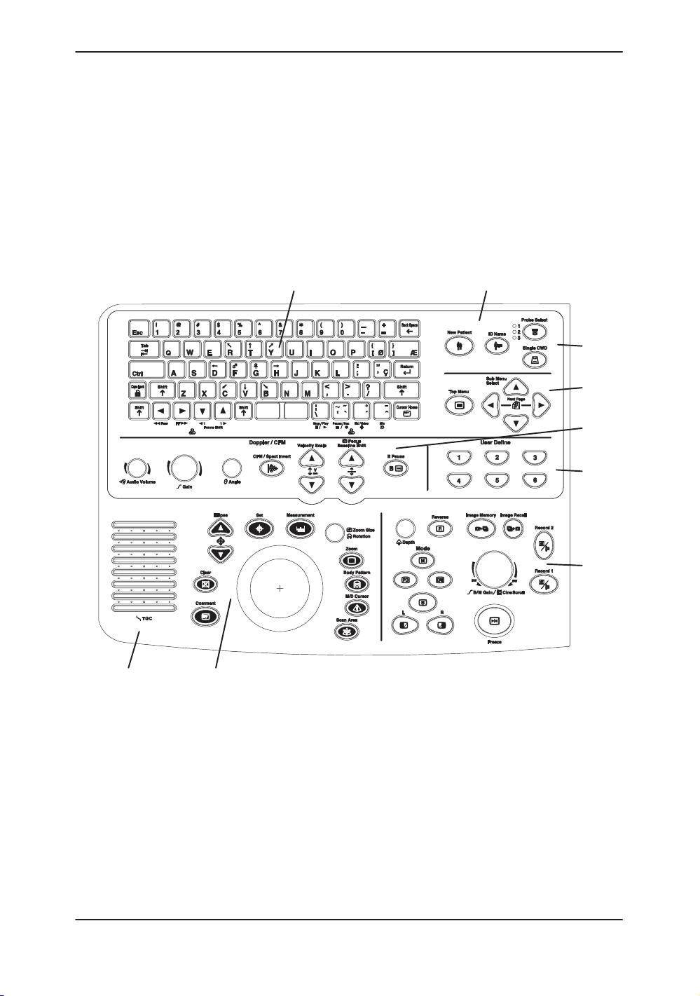
Control Panel Map
Operator Controls
Operator Controls
Controls are grouped together by function for ease of use. See
the callouts for this illustration on the following page.
98
1
2
3
4
5
6
7
LOGIQ 400 Basic User Manual
2260260–100 Rev . 1
Figure 3–22. Control Panel
3–35
Page 92

Operator Controls
Control Panel Map (cont’d)
Key Illumination
1. Alphanumeric Keyboard (see
2. Patient Information (see
3. Probe Selection (see
4. Soft Menu (see
5. Doppler CFM (see
6. User Define (see
7. Mode Display Record (see
8. Measurements/Annotations (see
9. TGC and Acoustic Output (see
All front panel keys have back lit illumination.
3–38
5–29
14–97
3–30
).
4–3
and
).
).
).
5–51
3–41
3–35
).
5–10
).
).
3–43
).
).
3–36
LOGIQ 400 Basic Users Manual
2260260–100 Rev . 1
Page 93

Keyboard
Red
Blue
Operator Controls
The standard alphanumeric keyboard has some special
functions.
The Cursor Home key brings the alphanumeric cursor to the
very upper left corner of the available field.
Control is used in conjunction with other keys to activate special
keyboard functions.
Tab is used to move forward or backwards through the text one
word at a time, or eight characters at a time.
Red Shift is used to activate language-specific and special
symbol characters highlighted in red on the keys to the right
side of the keyboard. See
For the LOGIQ 400, Blue Shift activates the VCR controls on
the keyboard for the approved Sony SVO-9500MD. The keys
can be used to control the Microphone, Stop, Play, Record and
Pause functions. The External Video key displays VCR video
on the monitor. Refer to the Advanced Reference Manual.
6–22
for details.
User Define Function
For the LOGIQ 400CL, Blue Shift activates two controls
associated with approved Sony SVO-9500MD. The keys can
be used to control the Microphone and External Video key to
display VCR video on the monitor.
Alphanumeric keys (A~Z and 1~0) can also be used for the
User Define Key function. Refer to
14–97
for details.
LOGIQ 400 Basic User Manual
2260260–100 Rev . 1
3–37
Page 94
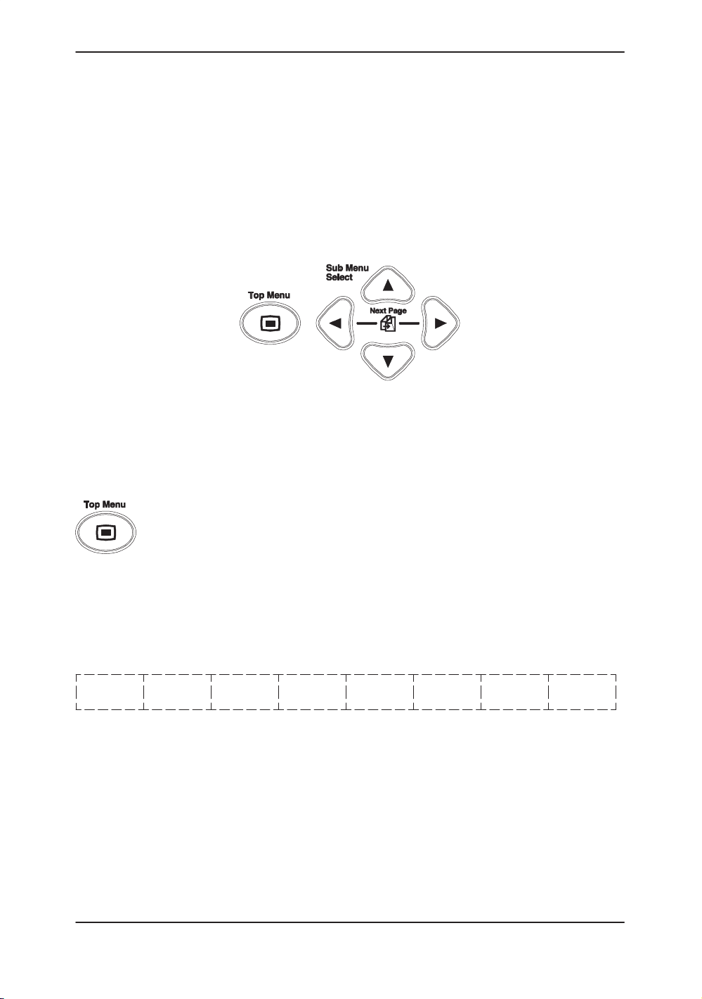
Operator Controls
Soft Menu Control Panel
Additional functionality, not available as a control or key on the
front panel, can be found via the Soft Menus. The Soft Menu is
displayed on the monitor. Different soft menus appear
depending on the mode, special function or calculation package
selected.
The Soft Menu consists of Top Menu Select and Sub-Menu
Select keys.
Figure 3–23. Soft Menu Control Keys
Top Menu Organization
The Top Menu Select key toggles the soft menu display on/off
or returns to the top menu display from a sub menu.
The default selection is the far left side top menu or the last
selection made prior to deactivating the soft menu display. One
page of its sub menus is automatically displayed when the top
menu is selected by an up/down arrow from the Sub Menu
Select keys.
The top menu groups are displayed as follows:
Mode Preset Set Up ECG Archive DICOM Auto CINE
Default Seq
Figure 3–24. Mode Default Top Menu
3–38
LOGIQ 400 Basic Users Manual
2260260–100 Rev . 1
Page 95

Top Menu Organization (cont’d)
S Mode Default Menu is the current highest priority active
mode. The five possibilities are “B”, “M”, “PWD”, “CWD”
and “CFM”.
Operator Controls
S Preset
S Set Up
S ECG (option) is used to adjust the ECG waveform and ECG
S Archive is used with the Image Archive option for storing
S DICOM (option) displays sub-menus for DICOM setup.
S Auto Sequence displays the user programmed
S CINE
Four keys on the front panel automatically disable all top menus
and display specific sub-menu selections.
S Body Pattern displays the available graphic selections in
S Comment displays the available selections from the
S Measurement displays the available measurements
is for user programmable application and factory
exam parameter preset selections.
enables the system customization sub-menus.
synchronized scanning.
images to MOD.
measurement sequences.
is used when the image is frozen for review of the
accumulated image data.
the sub-menu area.
comment library.
suitable for the current exam category, image format or
individual user sequences.
S Image Recall displays information pertaining to images
NOTE: To return functions to the Top-Menus, press Clear.
.
LOGIQ 400 Basic User Manual
2260260–100 Rev . 1
temporarily stored in system memory.
3–39
Page 96

Operator Controls
Sub-Menu Organization
Different Sub-Menus are displayed according to the front panel
key pressed or Top Menu selected.
Each selection or parameter in the Sub-Menus relates directly
to the Top Menu that is highlighted.
Sub Menu Select keys turn on a sub menu, move through the
sub menu selections and pages, change sub menu values or
turn on/off sub menu selections.
The up/down arrow keys turn on the sub menu.
The left/right arrow keys move through the menu selections and
pages.
The up/down arrow keys change the highlighted selection value
or turn the sub menu selection on/off.
Refer to Figure 3–25. The top row shows the top menu
selected “B” and the number of pages available 1 of 4.
The second row are the parameter selections available. Below
each parameter selection is a value or up/down arrows that
may indicate increase/decrease or on/off.
3–40
1/4B
Dynamic
Range
Gray
Map
42
Focus
Number
B–2 2
ATO
Create
Figure 3–25. B Sub-Menu Organization
ATO
On/Off
LOGIQ 400 Basic Users Manual
2260260–100 Rev . 1
Page 97

Mode, Display and Record
This group of controls provides various functions relating to the
display mode, display orientation, image recording/saving,
freeze, gain and cine scroll.
The Mode Controls select the desired display mode or
combinations of display modes.
During dual display modes the L and R keys activate the Left or
Right displayed image.
Operator Controls
Increase Decrease
The Depth knob controls the image display depth.
The Reverse key toggles the left/right orientation of the scan
image.
The Image Memory key stores the current frozen displayed
image in system image memory.
Maximum number of B-Mode images is 8.
Maximum number of Timeline images is 4.
All images are erased when the New Patient key is pressed or
there is a loss of system power.
The Image Recall key displays a menu of the images stored in
memory. After pressing Image Recall, select the desired
image from the Soft Menu for display .
LOGIQ 400 Basic User Manual
2260260–100 Rev . 1
3–41
Page 98

Operator Controls
Mode, Display and Record (cont’d)
Record 1 and Record 2 are used to activate/print the
designated recording device (i.e. video page printer,
multi-image camera, image archive option).
The Freeze key is used to stop the acquisition of ultrasound
data and freeze the image in system memory.
Pressing Freeze a second time continues live image data
acquisition.
Controls the gain of the displayed echoes during B-Mode
scanning. Controls the gain of the displayed timeline echoes
during B/M- and M-Mode. During B/M-Mode, B-Mode gain can
be controlled by the Doppler/CFM Angle Control.
The gain value displayed on the monitor is:
B-Mode B-Mode Gain
M-Mode M-Mode Gain
B/M-Mode M-Mode Gain
When the image is frozen it controls scrolling forwards and
backwards through the cine loop images in temporary memory.
3–42
LOGIQ 400 Basic Users Manual
2260260–100 Rev . 1
Page 99

Measurement and Annotation
This group of controls performs various functions related to
making measurements, annotating and adjusting the image
information.
The Comment key enables the image text editor and displays
the annotation library soft menu. For more details, refer to
6–16
.
The Body Pattern key enables the body pattern Soft Menu and
displays the default pattern on the screen. For more details,
refer to
The M/D Cursor key enables Trackball control of the M-Mode or
Doppler cursor line (not angle correction) or the CFM window in
real-time Color Flow Mode.
The Scan Area key enables Trackball control of the B-Mode
image area size and position in B/W, the CFM window size and
position in Color mode and the Zoomed area size and position
in Zoom.
6–27
Operator Controls
.
The Measurement key is used in all types of basic
measurements. It displays the measurement soft menu for the
current exam category.
LOGIQ 400 Basic User Manual
2260260–100 Rev . 1
3–43
Page 100
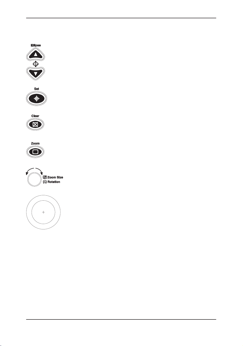
Operator Controls
Measurement and Annotation (cont’d)
The Ellipse keys are used to activate the ellipse measurement
function after the first distance measurement has been set. It
also toggles which cursor is the movable cursor during the
ellipse adjustment.
The Set key is used for various functions, but is generally used
to fix or finish an operation (i.e. to fix a measurement cursor or
exit scan area size/position in B-Mode and zoom).
The Clear key is generally used to erase or exit functions such
as annotations/comments, measurements and zoom. This will
return the system to the basic mode top menu.
Press the Zoom key to activate the zoom function. For more
details, refer to
6–2
.
This knob is used to control the zoom size with the zoom
function in real-time or rotate the probe position indicator in the
body pattern function.
The Trackball is used with almost every key function in this
group. Trackball control depends on the last key function
pressed.
3–44
LOGIQ 400 Basic Users Manual
2260260–100 Rev . 1
 Loading...