

Page 1
1.0 INTRODUCTION
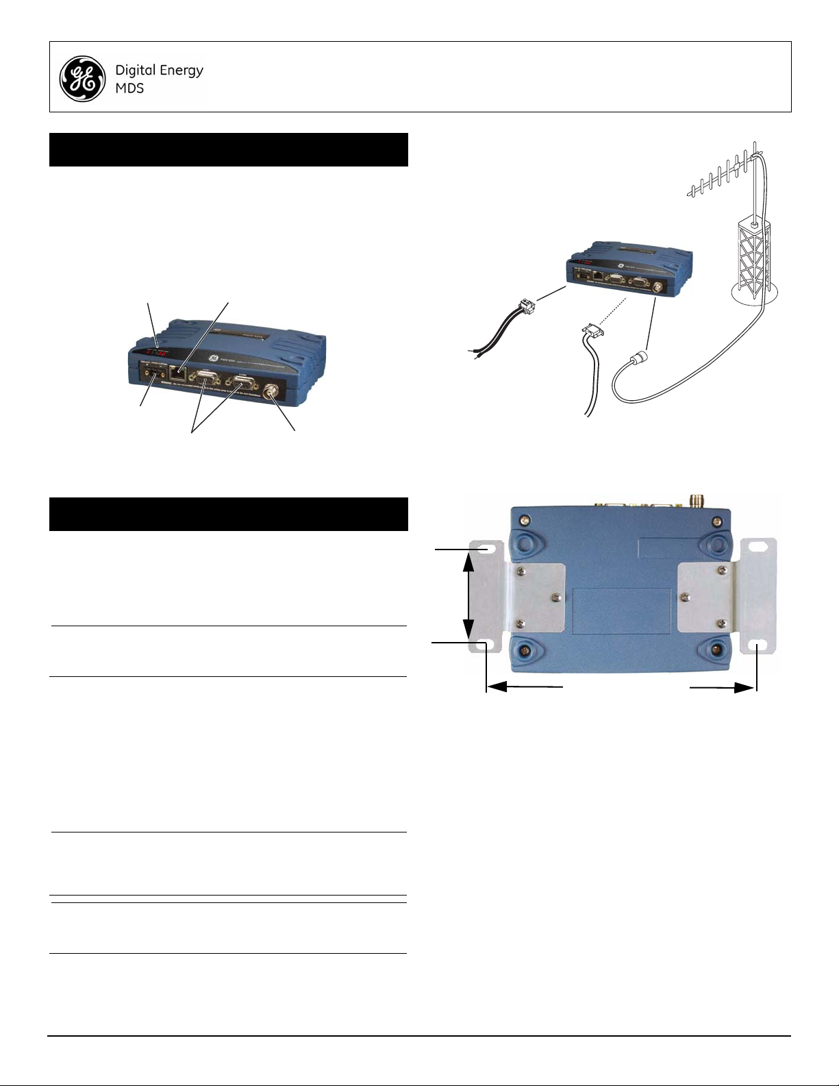
ANTENNA
CONNECTOR (TNC)
SERIAL DATA
CONNECTORS (DB-9)
DC INPUT
POWER
LED INDICATOR
PANEL
ETHERNET
CONNECTOR (RJ-45)
COM1 used for radio management
DC POWER SUPPLY
Negative Ground Only
TRANSCEIVER
LOW-LOSS FEEDLINE
ANTENNA SYSTEM
SERIAL
Master Stations typically use
omni-directional antenna
TO
DATA TELEMETRY
DEVICE
7.25˝ (16.99 cm)
2.75˝ (7 cm)
The MDS SD1 transceiver (Figure 1) is a software-configurable,
industrial solution for use in wireless telemetry applications. The
unit operates in the 150-174 MHz frequency band.
The radio interfaces with a variety of data control equipment such
as remote terminal units (RTUs), programmable logic controllers
(PLCs), flow computers, and similar devices. Data interface connections may be made by both serial (RS-232/485) and limited
Ethernet protocols.
MDS SD1 Transceiver
Quick Start Guide (x710 Mode)
2.0 INSTALLATION
There are three main requirements for installing the transceiver:
• Adequate and stable primary power
• An efficient and properly installed antenna system
• Correct interface connections between the transceiver and
the data device.
Figure 2 shows a typical installation of the radio.
NOTE: Retrofit Kits are available to simplify installation at former
2.1 Installation Steps
In most cases, the steps given here are sufficient to install the
transceiver. Refer to the Reference Manual for additional details,
as required.
1. Mount the transceiver using the brackets supplied. Attach
NOTE: To prevent moisture from entering the radio, do not mount
CAUTION:Using screws longer than 1/4 inch (6 mm) to attach the
MDS x710 digital and analog sites. Consult the Reference Manual for ordering details.
the brackets to the bottom of the transceiver case (if not
already attached), using the four 6-32 x 1/4 inch (6 mm)
screws supplied. Mounting bracket dimensions are shown in
Figure 3. If DIN Rail mounting brackets are to be used, consult
the Reference Manual.
the case with the cable connectors pointing up. Also,
dress all cables to prevent moisture from running along
the cables and into the radio.
Invisible place holder
Figure 1. MDS SD1 Data Transceiver
brackets to the radio may cause internal damage. Use
only the screws supplied.
Figure 2. Typical Installation (Remote Site Show n)
Figure 3. Mounting Bracket Dimensions
2. Install the antenna and feedline. The antenna used with the
radio must be designed to operate in the radio’s frequency
band, and be mounted in a location providing a clear path to
the associated station(s). At Remote sites, aim directional
antennas toward the Master Station. Low loss coaxial feedline
should be used and it should be kept as short as possible.
3. Connect the data equipment. Connection may be made to
the COM port using Serial protocols (RS-232/RS-485).
• Connect your data equipment to the appropriate serial port
on the front panel. (Typically, COM2 is used for connecting
data equipment, and COM1 is used for management of the
radio. Other arrangements are possible. Refer to the Refer-
ence Manual for details.) In all cases, the radio is hardwired
as a DCE device. A straight-thru cable may be used for most
applications.
4. Connect primary power. Input power must be 10.0 to 30 Vdc
and capable of providing at least 2.5 Amperes. A power connector with screw-terminals is provided wit h th e un i t (se e
05-6358A01, Rev. 02 (FCC) MDS SD Series Quick Start Guide (x710 Mode) 1
Page 2
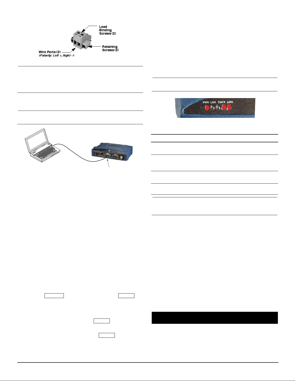
Figure 4). Strip the wire leads to 6 mm (1/4 inch) and insert
PC Running Terminal Session
Transceiver
DB-9M to COM1 Port
ESCAPE
ENTER
ENTER
ENTER
them into the wire ports. Be sure to observe proper polarity as
shown below. Tighten the binding screws securely.
Figure 4. DC Power Connector
CAUTION:The unit is designed for use with negative-ground
systems only. The power supply should be equipped
with overload protection (NEC Class 2 rating), to
protect against a short circuit between its output terminals and the radio’s power connector.
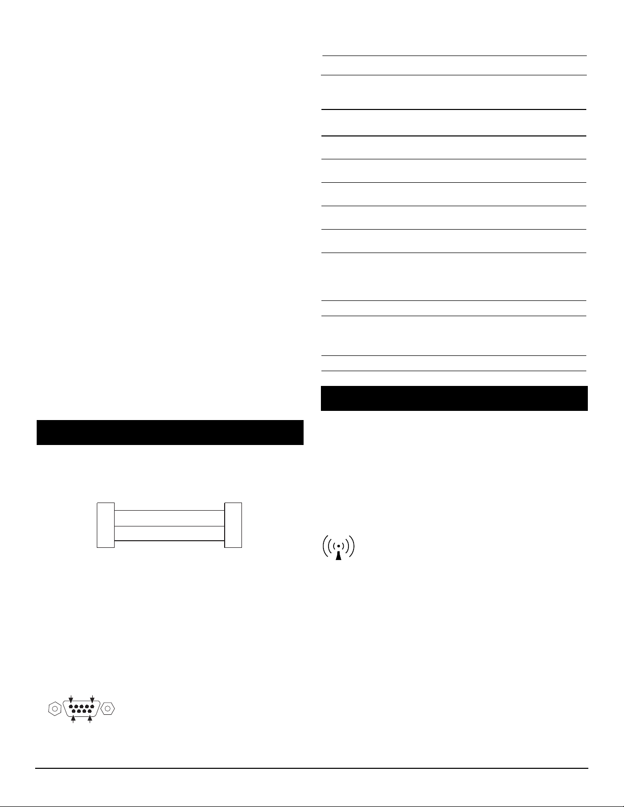
5. Set the radio’s configuration. Connect a PC to the radio’s
COM1 port as shown in Figure 5. A straight-thru cable may be
used for this connection.
MODEM command. Use MODEM [xxxx] if changes are
required, where xxxx represents the modem speed in bps.
When finished with the steps above, review the other configuration options to determine if other settings are required for
your system. Table 3 lists key software commands for the
radio.
2.2 Initial Checkout
In-service operation of the transceiver is completely automatic.
The only operator actions required are to apply DC power and
observe the LEDS for proper indications. Table 1 summarizes the
radio’s LED functions.
2.2.1 LED Functions
NOTE: LED labeling may vary on early un its. LED position and
functionality remains as described below.
NOTE: Consult your System Administrator if you are unsure of
the settings required for your network.
Figure 5. Setup for PC Configuration
2.1.1 Software Configuration
There are two methods for communicating with the radio for configuration and management: Serial (COM1 DB9 connector) and
Telnet (ETHERNET RJ-45 connector). Both present identical
functionality, but the method of access is different for each. The
focus here is on Serial access, but Telnet may be used by following
these additional points, which replace Steps 1 and 2 below:
• For Telnet, connect to the radio with a PC that is on the
same IP network as the transceiver. Launch a Telnet program, and connect to the radio using its programmed IP
address.
• The default IP address is 192.168.1.1. If you do not know the
IP address of the radio, use the serial configuration steps
below to view the address with the IPCONFIG command.
1. With a PC connected to the COM1 serial port, launch a
terminal program, such as HyperTerminal (included with most
pre-Vista Windows®-based PCs) and set the following
parameters:
8 bits, no parity, one stop bit (8N1), flow control disabled,
VT100 emulation. The radio’s COM1 port automatically
determines the connected baud rate (within the range of
1200–115200 bps).
2. Press the key followed by a series of
keypresses (1/2 second intervals) until the > prompt appears.
The radio is now ready to accept commands.
3. Set/verify the RX (receive) and TX (transmit) frequencies. To
set the receive frequency, enter RX followed by the correct fre-
quency in MHz (xxx.xxxxx). Press .
To set the transmit frequency, enter TX followed by the correct
frequency in MHz (xxx.xxxxx). Press .
4. The factory default modem settings support operation for most
systems. Other options are available using the proper software commands. The current setting may be viewed using the
Figure 6. LED Status Indicators
Table 1: Description of LED Status Indicators
LED Name Description
PWR • Continuous—Power applied, no problems detected.
• Rapid flash (5x-per-second)—Alarm indication.
LAN • Flashing—Ethernet data activity is detected.
• Off—Ethernet signals not detected, or excessive
traffic is present at the port.
DATA1/DATA2 These LEDs show data activity on the DB-9 serial
LINK When lit, indicates that a communication link exists
NOTE: The Ethernet connector also has two embedded LEDs. A
flashing green indicates Ethernet data activity, and a
yellow indicates 100 Mbps operation has been achieved.
payload port(s).
with the master station.
2.2.2 Antenna SWR Check
Before placing the unit in final operation, the antenna system’s
standing wave ratio (SWR) should be checked using a wattmeter
suited to the frequency of operation. High SWR (above 2:1) may
indicate an antenna or feedline problem, and should be corrected.
2.2.3 RSSI Check (for Remotes)
Using the RSSI command (received signal strength indication),
check for adequate signal strength. The radio must be receiving a
signal from the associated Master Station (LINK LED on or
blinking). In general, signal levels stronger than –80 dBm will provide very reliable communication and allow for a degree of “fade
margin.”
Optimize the RSSI at Remotes by slowly adjusting the direction of
the station antenna. Watch the RSSI indication for several seconds
after making each adjustment so that the RSSI accurately reflects
any change in the signal strength. With RSSI, the less negative the
number, the stronger the incoming signal (i.e., -70 dBm is stronger
than -80 dBm).
3.0 TROUBLESHOOTING
All radios in the network must meet the following basic requirements for proper operation. Check these items first when troubleshooting a communication problem:
• Adequate and stable primary power
• Secure cable connections (RF, data and power)
• A clear transmission path between Master and each Remote
2 MDS SD Series Quick Start Guide (x710 Mode) 05-6358A01, Rev. 02 (FCC)
Page 3
• An efficient and properly aligned antenna system providing
RXD
TXD
GND
2
3
5
RXD
TXD
GND
2
3
5
>
<
DB-9 FEMALE
(COMPUTER)
DB-9 MALE
(RADIO SIDE)
5
96
1
RF Exposure Notice
adequate received signal strength.
• Proper programming of the transceiver’s parameters
• The correct interface between the transceiver and the connected data equipment (correct cable wiring, proper data
format, timing, etc.)
3.1 LEDs
The radio’s LED indicator panel provides useful information when
troubleshooting a system problem. Refer to Table 1 for LED information.
3.2 Event Codes
When an alarm condition exists, the transceiver creates a message that can be read on a connected PC by using the ALARM
command. Consult the Reference Manual for details.
3.2.1 Types of Alarms
Minor Alarms—report conditions that, under most circumstances
will not prevent transceiver operation. This includes out-of-tolerance conditions, baud rate mismatches, etc. The cause of these
alarms should be investigated and corrected to prevent system
failure.
Major Alarms—report serious conditions that generally indicate a
hardware failure, or other abnormal condition that will prevent (or
seriously hamper) further operation of the transceiver. Major
alarms may require factory repair. Contact your factory representative for assistance.
3.3 Built-In Spectrum Analyzer
A Spectrum Analyzer screen is available for viewing other radio
signals near the SD’s operating frequencies. Access to the analyzer is made with the Spectrum command.
Optionally, you can specify a frequency at the prompt to view the
surrounding spectrum of that frequency To do this, enter Spec-
trum xxx.xx, where xxx.xx is the frequency in MHz.
The display creates a received signal strength indication (RSSI)
vs. frequency plot for the frequency and surrounding signals. Refer
to the Reference Manual for more information.
4.2.1 Pin Descriptions—RS-232 Mode
Table 2 provides pin descriptions for the connector when operating
in RS-232 mode. For RS-422/485, refer to the Reference Manual.
NOTE: The radio is hard-wired as a DCE device.
Table 2: COM2 Pin Descriptions—RS-232
Pin
Input/
No.
Output Pin Description
1OUTDCD (Data Carrier Detect/Link)—A low
2OUTRXD (Received Data)—Supplies received data to
3INTXD (Transmitted Data)—Accepts TX data from
4INSleep Mode Input—Grounding this pin places the
5--Signal Ground—Connects to ground (negative
6OUTAlarm Output (DSR)—Behavior is
7INRTS (Request-to-Send)—Keys the transmitter.
8OUTCTS (Clear-to-Send)—Goes “high” after the
9 -- Reserved—User I/O for special applications.
indicates signal received.
the connected device.
the connected device.
radio in a low power consumption mode.
supply potential) on chassis.
user-configurable. Default behavior: An RS-232
high/space (+5.0 Vdc) on this pin indicates an
alarm condition. An RS-232 low/mark (–5.0 Vdc)
indicates normal operation.
programmed CTS delay time has elapsed (DCE),
or keys another connected radio when RF data
arrives (CTS KEY).
5.0 COMMAND OVERVIEW
4.0 COM1/COM2 REFERENCE
4.1 COM1 Connections for PC Control
The COM1 DB-9 connector is used for PC management of the
radio. A straight-through cable is required that connects Pin 2
(RXD), Pin 3 (TXD), and Pin 5 (Ground). (See Figure 7.)
Figure 7. COM1 Wiring to Computer
4.2 COM2 Connections
The COM2 connector (Figure 8) is typically used to connect an
external DTE telemetry device to the radio, supporting the RS-232
or RS-485 (balanced) format, depending on how the radio is configured. The radio supports data rates of 300, 1200, 2400, 4800,
9600, 19200, 38400, 57600, and 115200 bps (asynchronous data
only).
The COM2 connector mates with a standard DB-9 plug available
from many electronics parts distributors.
Figure 8. COM2 Connector (DB-9F)
As viewed from outside the radio
Table 3 on the following page lists key software commands for the
SD transceiver. Many commands can be used in two ways:
1. The basic command (shown first) may be entered alone to
issue a query or execute a simple command.
2. The basic command may be appended with additional arguments (shown in brackets, if applicable) to further define a setting.
A complete list of commands and detailed descriptions is provided
in the SD Reference Manual (under development for SD1).
The concentrated energy from a directional antenna may pose a health
hazard. Do not allow people to come closer than 1.80 meters to the front
of the antenna when the transmitter is operating with a 7 dBd (9.15 dBi)
gain antenna. Use of higher gain antennas means increasing the distance
accordingly. This guide is intended for use by a professional installer. More
information about RF exposure can be accessed online at the following
address:
www.fcc.gov/oet/info/documents/bulletins
L'énergie concentrée en provenance d'une antenne directionnelle peut
présenter un danger pour la santé. Ne pas permettre aux gens de
s'approcher à moins de 1,80 mètres à l'avant de l'antenne lorsque l'émetteur est en opération avec une antenne ayant un gain de 7 dBd (9,15 dBi).
On doit augmenter la distance proportionnellement si on utilise des
antennes ayant un gain plus élevé . Ce guide est destiné à être utilisé par
un installateur professionnel. Plus d'informations sur l'exposition aux
rayons RF peut être consulté en ligne à l'adresse suivante:
www.fcc.gov/oet/info/documents/bulletins
05-6358A01, Rev. 02 (FCC) MDS SD1 Quick Start Guide (x710 Mode) 3
Page 4

Industry Canada Notice
This Class A digital apparatus complies with Canadian ICES-003. Cet
appareil numérique de la classe A est conforme à la norme NMB-003 du
Canada.
FCC Part 15 Notice
This equipment has been tested and found to comply with the limits for a
Class A digital device, pursuant to part 15 of the FCC Rules. These limits
are designed to provide reasonable protection against harmful interference
when the equipment is operated in a commercial environment. This equipment generates, uses, and can radiate radio frequency energy and, if not
installed and used in accordance with the instruction manual, may cause
harmful interference to radio communications. Operation of this equipment
in a residential area is likely to cause harmful interference in which case the
user will be required to correct the interference at his own expense.
Operation of this device subject to the following two conditions:
(1) this device may not cause harmful interference, and (2) this device must
accept any interference received, including interference that may cause
undesired operation. Any unauthorized modification or changes to this
device without the express approval of the manufacturer may void the
user’s authority to operate this device. Furthermore, this device is intended
to be used only when installed in accordance with the instructions outlined
in this guide. Failure to comply with these instructions may void the user’s
authority to operate this device.
.
GE MDS, LLC
175 Science Parkway
Rochester, NY 14620
MDS SD1 Transceiver (x710 Mode) General Business: +1 585 242-9600
05-6358A01, Rev. 02 (FCC) FAX: +1 585 242-9620
February 2011 Web: www.gemds.com
Page 5

T able 3: Key Software Commands
Command Function
ALARM Read current operating condition of the radio.
BAUD [xxxxx abc] Set/display the data rate and control bits.
BUFF [ON, OFF] Enables or disables the internal radio data
CTS [0-255] Set/display the Clear-to-Send delay in
DEV Display modem control deviation.
DEVICE [DCE, CTS KEY] Set/display device mode.
DKEY Dekey the radio (transmitter OFF). This is
DUMP Display all programmable settings.
HELP Shows available commands.
KEY Key the radio (transmitter ON). This is
MODEM [xxxx] Set the modem characteristics of the radio.
PORT [RS232, RS485] Set/display COM2 data port interface
PTT [0-255] Set/display the Push-to-Talk delay in
PWR [20-37] Set/display the transmit power setting.
RSSI Display the Received Signal Strength
RTU [ON/OFF/0-80] Re-enables or disables the radio’s internal
RX [xxx.xxxx] Set/display the receive frequency.
RXLEVEL [-20 to 0] Set/display the receive audio input level.
SCD [0-255] Set/display the Soft-Carrier Dekey delay in
SHOW [DC, PWR] Display the DC voltages and transmit power
SNR Signal-to-Noise Ratio, expressed in dB
SPECTRUM [xxx.xx] Display the transceiver’s built-in spectrum
STAT Display radio status and alarms.
TEMP Display the internal temperature of the radio
TOT [1-255, ON, OFF] Set/display the Time-out Timer delay in
TX [xxx.xxxx] Set/display the transmit frequency.
TXLEVEL [-20 to 0, AUTO] Set/display the transmit audio input level.
UNIT [10000...65000] Set/display the transceiver’s unit address.
buffer.
seconds.
generally a radio test command.
generally used as a radio test command.
settings.
milliseconds.
Indication.
RTU simulator and sets the RTU address.
milliseconds.
level.
analyzer, where xxx.xx denotes center
frequency.
in degrees C.
seconds.
05-6358A01, Rev. 02 (FCC) MDS SD1 Quick Start Guide (x710 Mode) 5
 Loading...