

Page 1
CarrierComm
CarrierWave-100/155
User Reference and Installation Manual
Document Number: MK-MAN-01 Rev: B
Date: 11 March 2003
Page 2

CarrierWave Digital Radio Manual Dwg # MK-MAN-01; Revision Levels: A
Section Drawing No: REV Revised /
Released
CW-100
CW-155
MK-MAN-01 A SN Initial Release
B Added antenna professional installation
Reason
and FCC clarification statements.
MK-MAN-01 CarrierWave Digital Radio
Page 3

Table of Contents
1 SAFETY PRECAUTIONS ............................................................................................................. 1-1
2 SYSTEM DESCRIPTION..............................................................................................................2-1
2.1 About This Manual ...........................................................................................................................................................2-1
2.2 Introduction ........................................................................................................................................................................2-1
2.3 System Features.................................................................................................................................................................2-4
2.4 Physical Description ..........................................................................................................................................................2-5
2.4.1 Model Types ...............................................................................................................................................................2-5
2.4.2 Front Panel Indicators ................................................................................................................................................2-6
2.4.3 Rear Panel Connections............................................................................................................................................2-8
2.5 System Description .........................................................................................................................................................2-10
2.6 Consecutive Point Architecture .................................................................................................................................. 2-12
2.7 Power Management........................................................................................................................................................2-15
2.8 CarrierWave iWareTM Software and Network Management ............................................................................ 2-16
3 INSTALLATION...........................................................................................................................3-1
3.1 Unpacking............................................................................................................................................................................3-1
3.2 Notices ..................................................................................................................................................................................3-2
3.3 PRE-INSTALLATION NOTES ....................................................................................................................................3-2
3.3.1 Back-to-Back Bench Testing....................................................................................................................................3-2
3.4 Overview of Installation and Testing Process...........................................................................................................3-3
3.5 Site Evaluation....................................................................................................................................................................3-5
3.5.1 Preparing for a Site Evaluation................................................................................................................................3-5
3.5.2 Site Evaluation Process .............................................................................................................................................3-6
3.5.3 Critical System Calculations....................................................................................................................................3-8
3.5.4 Documenting a Site Evaluation..............................................................................................................................3-11
3.6 Installation of the CarrierWave Digital Radio.......................................................................................................3-14
3.6.1 Installing the CarrierWave IDU.............................................................................................................................3-14
3.6.2 Installing the CarrierWave ODU............................................................................................................................3-15
3.6.3 Routing the ODU/IDU Interconnect Cable..........................................................................................................3-20
3.6.4 Grounding the System.............................................................................................................................................3-21
3.7 Configuration of the CarrierWave Digital Radio..................................................................................................3-23
3.7.1 Materials Required...................................................................................................................................................3-23
3.7.2 IDU Configuration Process....................................................................................................................................3-24
3.7.3 Documenting CarrierWave Digital Radio Configuration ..................................................................................3-34
4 FRONT PANEL OPERATION.......................................................................................................4-1
4.1 Introduction ........................................................................................................................................................................4-1
4.2 Front Panel Operation .....................................................................................................................................................4-1
4.2.1 LCD Display................................................................................................................................................................4-1
4.2.2 Cursor and Screen Control Buttons .........................................................................................................................4-2
4.3 LED Status Indicators ......................................................................................................................................................4-3
4.4 Screen Menus......................................................................................................................................................................4-4
4.4.1 Text Screens................................................................................................................................................................4-5
CarrierWave Digital Radio MK-MAN-01
Page 4

4.4.2 Menu Screen................................................................................................................................................................4-5
4.5 Menu Tree Structure ........................................................................................................................................................4-7
4.6 Screen Menu Summaries..............................................................................................................................................4-11
4.6.1 Modify Config/Link Params ...................................................................................................................................4-12
4.6.2 Modify Config/TX Control.....................................................................................................................................4-13
4.6.3 Modify Config/Adaptive Pwr Ctrl.........................................................................................................................4-14
4.6.4 Display Config/Display RX Config/Radio ...........................................................................................................4-14
4.6.5 Display Config/Display Rx Config/Demod/Decoder.........................................................................................4-14
4.6.6 Display Config/Display TX Config/Radio...........................................................................................................4-15
4.6.7 Display Config/Display Tx Config/Mod/Encoder..............................................................................................4-15
4.6.8 Display Config/Adaptive Pwr Ctrl.........................................................................................................................4-16
4.6.9 Display Config/Network Config............................................................................................................................4-16
4.6.10 Display Config/OA&M Params .............................................................................................................................4-17
4.6.11 Monitor Status/Display RX Status........................................................................................................................4-17
4.6.12 Monitor Status/Display Cur Alarms ......................................................................................................................4-17
5 SUMMARY SPECIFICATION .......................................................................................................5-1
6 REAR PANEL CONNECT ORS .....................................................................................................6-1
6.1 DC Input (Power) Connector .........................................................................................................................................6-1
6.2 CarrierWave-100 Ethernet 100BaseTX Payload LOC Connector......................................................................6-1
6.3 CarrierWave-100 Ethernet 100BaseTX CPT Connector .......................................................................................6-3
6.4 CarrierWave-155 SONET Payload Connector .........................................................................................................6-3
6.5 NMS 10/100BaseTX LOC Connector ..........................................................................................................................6-4
6.6 NMS 10/100BaseTX CPT Connector...........................................................................................................................6-5
6.7 Alarm Port Connector ......................................................................................................................................................6-6
6.8 T1- A Wayside Channel Connector..............................................................................................................................6-7
6.9 T1- B Wayside Channel Connector ..............................................................................................................................6-8
6.10 ODU Connector ..................................................................................................................................................................6-8
7 APPENDIX .................................................................................................................................. 7-1
7.1 Abbreviations & Acronyms ............................................................................................................................................7-1
7.2 Conversion Chart..............................................................................................................................................................7-4
MK-MAN-01 CarrierWave Digital Radio
Page 5
1 Safety Precautions
PLEASE READ THESE SAFETY PRECAUTIONS!
RF Energy Health Hazard
The radio equipment described in this guide uses radio frequency transmitters. Although the
power level is low, the concentrated energy from a directional antenna may pose a health hazard.
Do not allow people to come in close proximity to the front of the antenna while the transmitter is
operating. The antenna will be professional installed on fixed-mounted outdoor permanent
structures to provide separation from any other antenna and all persons as detailed on page 1-2.
Protection from Lightning
Article 810 of the US National Electric Department of Energy Handbook 1996 specifies that radio
and television lead-in cables must have adequate surge protection at or near the point of entry to
the building. The code specifies that any shielded cable from an external antenna must have the
shield directly connected to a 10 AWG wire that connects to t he building ground electrode.
AB-Full Access Digital Radio MK-MAN-01
Page 6

1-2 Safety Precautions
FCC Notice, USA
Axxcelera Digital Radios comply with Part 15 of the FCC rules. The radios are specifically
designed to be used under Part 15, Section 15.247 of the FCC rules and regulations. Operat ion is
subject to followin g conditions:
• The device to utilize a fixed mount ant enna, for use on a permanent outd oor structure.
• The device to be installed by qualified installation/deployment personnel. When the
device is operating, a minimum separation must exist between the device and persons as
shown in the table below. The minimum distance is dependent up on ant enna size.
Antenna Size Minimum Distance (meters)
Integrated Antenna 2.0
External Antenna: <=3' dia. (gain <= 31.2dBi) 2.0
External Antenna: <=4' dia. (gain <= 35.3dBi) 3.0
External Antenna: <=6' dia. (gain <= 38.3dBi)) 4.2
• The device installers and operators should be aware of the transmitter operating
conditions, specified in the installation manual and other associated user documentation,
as well as the antenna co-location requirements of Part 1.1307 (b) (3), of FCC rules,
pertaining to RF expo sure.
• The device may not cause har mful interference.
• The device must accept interference received, including interference that may cause
undesired operation.
The device is intended to be used only when installed in accordance with instructions outlined in
this manual. Failure to comply with these instructions may void the user's authority to operate
this device and/or the manufacturer's warranty. Furthermore, any unauthorized modification or
changes to this device without the express approval of Axxcelera may also void the user's
authority to operate this dev ice.
FCC Part 15 Notice
This equipment has been tested and found to comply with the limits for a Class A digital device,
pursuant to Part 15 of the FCC Rules. These limits are designed to provide reasonable
protection against harmful interference when the equipment is operated in a commercial
environment. This equipme nt generates, uses, and can radiate radio frequency energy and, if not
installed and used in accordance with the instruction manual, may cause harmful interference to
radio communications. Operation of this equipment in a residential area may cause harmful
interference, in which case the user will be required to correct the interference at his expense.
Any external data or audio conn ection to this equipment must use shielded cables.
MK-MAN-01 AB-Full Access Digital Radio
Page 7

2 System Description
2.1 About This Manual
This manual is written for those who are involved in the “hands-on” installation of the CarrierWave
Digital Radio, such as installation technicians, site evaluators, project managers, and network
engineers. It assumes the reader has a basic understanding of how to install hardware, use
Windows based software, and operate test equipment.
2.2 Introduction
The CarrierWave family of digital license-free radios provides high capacity transmission,
flexibility, features, and convenience for wireless digital communications networks. The
CarrierWave digital radios are spectrum and data rate scalable, enabling service providers or
organizations to trade-off system gain with spectral efficiency and channel availability for optimal
network connectivity. CarrierComm’s digital radio family enables service providers and
enterprises to offer a portfolio of secure, scalable wireless applications for data, video, and Voice
over IP (VoIP).
The CarrierWave digital radio family operates in the Industrial, Scientific, and Medical (ISM)
band of 5.725 to 5.850 GHz, which is typically referred generically as 5.8 GHz. The
CarrierWave Digital Radio family supports two types of user data payload connectivity:
• SONET/SDH wireless bridging between two fixed coordinated locations without the delay
and expense of trenching fiber or the added costs of leasing dedicated OC-3 lines.
• 100Base-TX intelligent bridging between two locations without the delay and expense of
installing cable or traditional microwave
- Scalable Ethernet capability of 25 and 50 Mbps is included. These scalable radios
provide LAN connectivity and offer performance trade-offs between operational
bandwidths, data rates, and distance.
For customers such as cellular carriers requiring backhaul and backbone extension as well
as service providers requiring network redundancy, new Points of Presence (POPs), and last
mile access, the CarrierWave-155 radio is a cost effective alternative to leased lines with
carrier-class quality of performance. The CarrierWave-100 radio is a cost effective solution
to meet the growing demand for enterprise Local Area Network (LAN) connectivity between
buildings and campuses as well as service providers requiring reliable products for
infrastructure expansion, extending Metropolitan Area Network (MAN) fiber access, and
network redundancy.
CarrierWave Digital Radio MK-MAN-01
Page 8
2-2 System Description
The CarrierWave Digital Radio includes integrated Operations, Administration, Maintenance, and
Provisioning (OAM&P) functionality and design features enabling simple commissioning when the
radio network is initially set up in the field at the customer’s premises. Furthermore, a highlight of
CarrierComm’s radio products is scalability and the capability to support a ring-type architecture.
This ring or consecutive point radio architecture is self-healing in the event of an outage in the link
and automatically re-routes data traffic, thereby ensuring that service to the end user is not
interrupted.
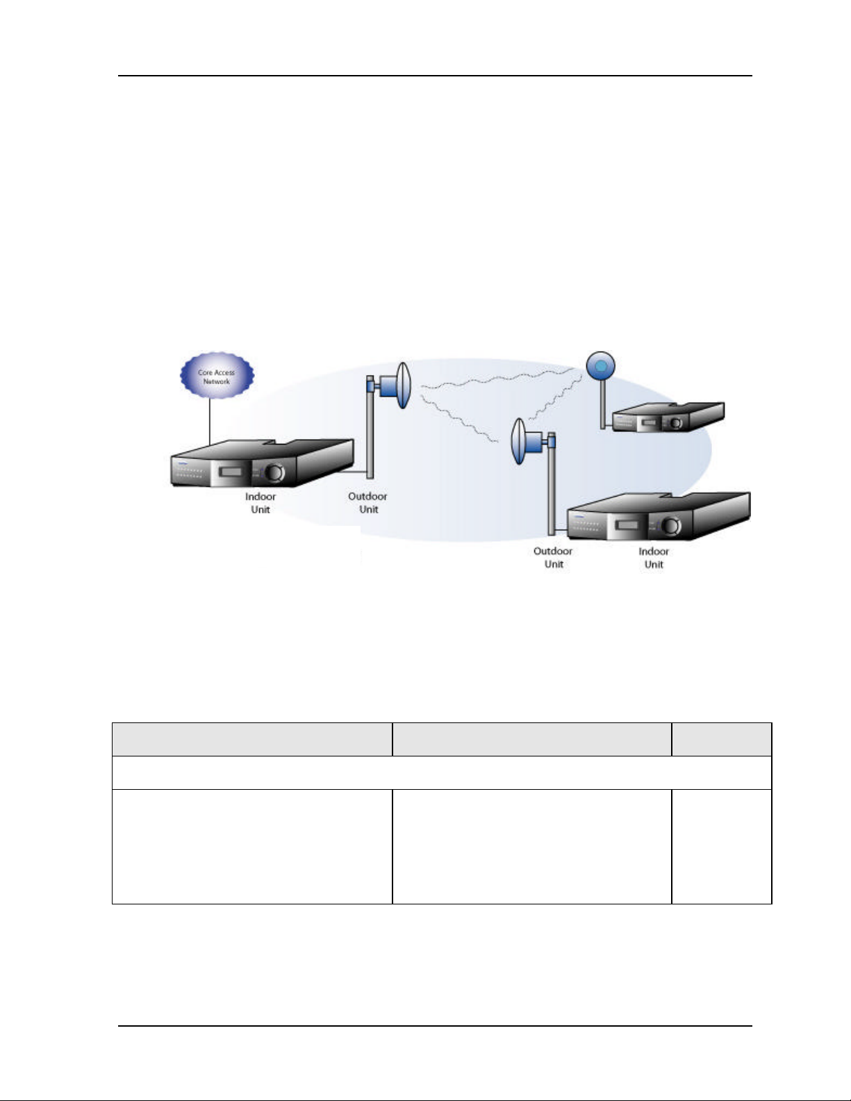
The overall architecture consists of a single 2RU rack mount Indoor Unit (IDU) with a cable
connecting to an Outdoor Unit (ODU) with an integrated antenna. There is an option for
interfacing the ODU with an external antenna (contact factory for availability). The IDU/ODU
architecture is advantageous when compared to a single IDU with external mount antenna since
supporting a signal of 5.8 GHz from the IDU rack to the antenna will experience significant signal
degradation requiring expensive coaxial cable or waveguide.
Figure 2-1. CarrierWave IDU/ODU Architecture
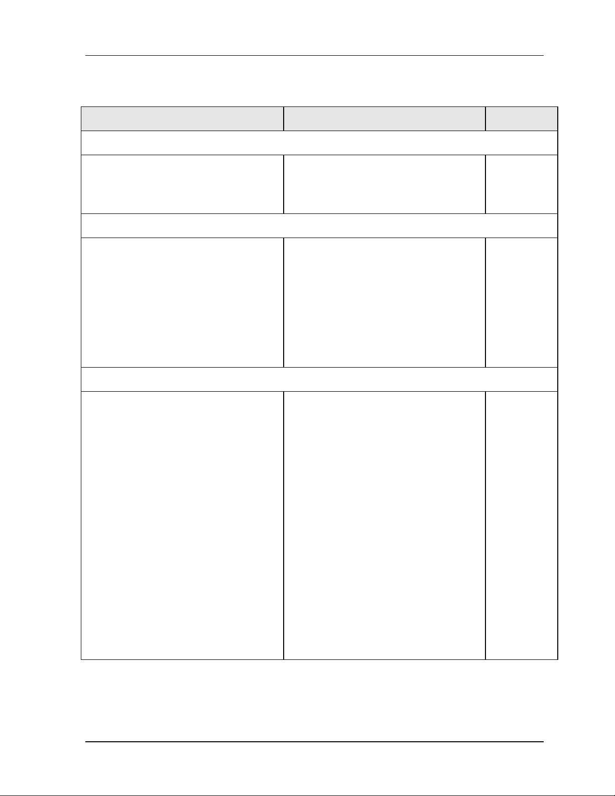
Table 2-1 lists key features that CarrierWave technology offers to those involved in the design,
deployment and support of broadband fixed wireless networks.
Table 2-1. Key Benefits and Advantages of CarrierWave Digital Radios
Benefits Advantages to Providers/Customers Reference
Wireless license-exempt system
ISM bands do not require expensive
license band fees or incur licensing delays.
Wireless connectivity supplements existing
fiber (SONET) or cable (Ethernet).
Fast return on investment.
Lower total cost of total ownership.
Media diversity avoids single points of
failure.
2.2 – 2.4
MK-MAN-01 CarrierWave Digital Radio
Page 9
User Reference and Installation Manual 2-3
Table 2-1. CarrierWave Digital Radio Benefits and Advantages to Providers
(continued)
Benefits Advantages to Providers/Customers Reference
Easy to install units
Straightforward modular system enables
fast deployment and activation.
Carrier-class reliability.
Complete support of payload capacity with additional wayside channels
Aggregate capacity beyond basic payload
(50 Mbps or 100 Mbps or 155 Mbps).
Scalable and spectrally efficient system.
Separate networks for radio
overhead/management and user payload.
Ring Architecture
Supports a ring (consecutive point)
configuration, thus creating a self-healing
redundancy that is more reliable than
traditional point-to-point networks.
In the event of an outage, traffic is
automatically rerouted via another part of
the ring without service interruption.
Fast return on investment.
No monthly leased line fees.
Increases available bandwidth of network.
Allows customer full use of revenue-
generating payload channel.
T1 wayside channels supports extension
of PBX connectivity between buildings
without additional leased-line costs.
Lowers total cost of ownership.
Enables network scalability.
Increases deployment scenarios for initial
deployment as well as network expansion
with reduced line-of-sight issues.
Increases network reliability due to selfhealing redundancy of the network.
3.1
2.2 – 2.5
2.4 – 2.5, 2.6,
3.7, 4.4
Ring/consecutive point networks can
overcome line-of-sight issues and reach
more buildings than other traditional
wireless networks.
Networks can be expanded by adding
more CarrierWave Digital Radios or more
rings without interruption of service.
A separate management channel allows
for a dedicated maintenance ring with
connections to each CarrierWave Digital
Radio on the ring.
CarrierWave Digital Radio MK-MAN-01
Minimizes total cost of ownership and
maintenance of the network.
Allows for mass deployment.
Page 10

2-4 System Description
Table 2-1. CarrierWave Digital Radio Benefits and Advantages to Providers
(continued)
Benefits Advantages to Providers/Customers Reference
Adaptive Power Control
Automatically adjusts transmit power in
discrete increments in response to RF
interference
Comprehensive Link/Network Management Software
A graphical user interface offers security,
configuration, fault, and performance
management via standard craft interfaces.
Suite of SNMP-compatible network
management tools that provide robust
local and remote management capabilities.
Enables dense deployment.
Simplifies deployment and network
management.
Simplifies management of radio network
and minimizes resources as entire network
can be centrally managed out of any
location.
Simplifies troubleshooting of single radios,
links, or entire networks.
Simplifies network upgrades with remote
software upgrades.
Allows for mass deployment.
2.3 System Features
2.5, 2.7
2.8, 3.7, 4.5
§ Selectable Rates
o CarrierWave-100/Ethernet: 25, 50, and 100 Mbps
o CarrierWave-155/SONET: 155 Mbps
§ Selectable Spectral Efficiency of 5 bits/Hz
§ QPSK, 16 –64 QAM Modulation
§ Powerful Trellis Coded Modulation concatenated with Reed-Solomon Error Correction
§ Built-in Adaptive Equalizer
§ Support of T1 Wayside Channels
o CarrierWave-100: 2 T1 channels
o CarrierWave-155: 1 T1 channel
MK-MAN-01 CarrierWave Digital Radio
Page 11

User Reference and Installation Manual 2-5
§ Peak output power: +30 dBm
§ Receive Sensitivity: -81 dBm (or lower, depending on data rate/modulation/FEC)
§ Adaptive Power Control
§ Built-in Network Management System (NMS)
§ Consecutive Point ring architecture
§ Built-in Bit Error Rate (BER) performance monitoring
2.4 Physical Description
The following section details the physical features of the CarrierWave digital radios
• Model types
• Front and rear panel configurations
• LED descriptions
2.4.1 Model Types
Table 2-2 lists the CarrierWave digital radios according to model number and associated
capabilities of throughput, data interface, and wayside channel.
Table 2-2.CarrierWave Model Types
Product Name Model Number Throughput Data Interface Wayside
CarrierWave-100 5100 100 Mbps
full duplex
CarrierWave-155 5155 155 Mbps
full duplex
100 BaseTX Two T1s
OC-3 One T1
CarrierWave Digital Radio MK-MAN-01
Page 12
2-6 System Description
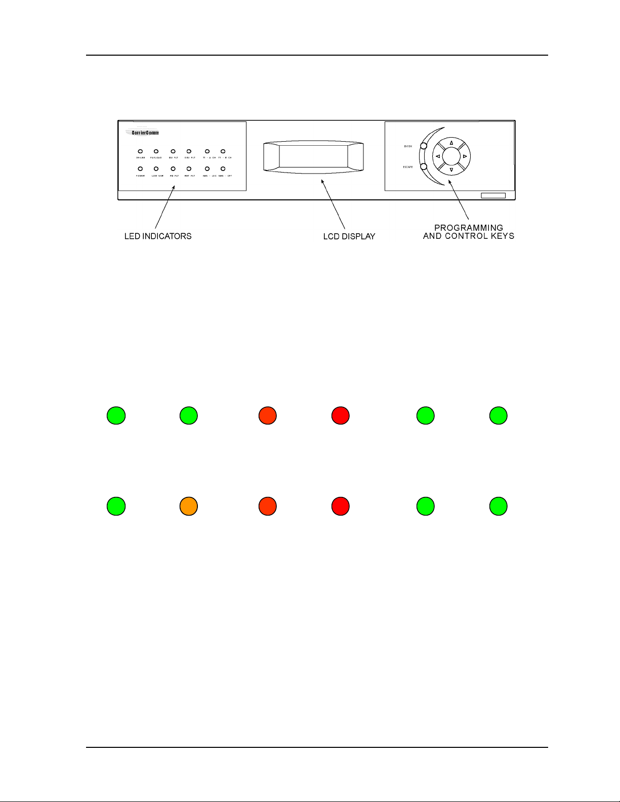
2.4.2 Front Panel Indicators
All models of the CarrierWave Digital Radios have the following front panel configurations.
Figure 2-2. CarrierWave Digital Radio IDU Front Panel Configuration
The basic operation of the CarrierWave Digital Radio can be checked by viewing the LED
indicators on the front panel. Normally, only green LEDs should be lit. A yellow LED indicates
potential system degradation, though the link is still active and operational. A red LED is an
alarm indicator. If it is lit, it indicates a potential problem in the radio system. Refer to Figure 2-3
and the table that follows for a detailed explanation of the LED indicators.
ON-LINE T1 - A CHPAYLOAD
POWER LOW SNR RX FLT
Figure 2-3. IDU Front Panel LEDs
ODU FLTIDU FLT T1 - B CH
RMT FLT NMS - LOC
NMS - CPT
MK-MAN-01 CarrierWave Digital Radio
Page 13

User Reference and Installation Manual 2-7
Table 2-3. LED Status Indicator Functions
LED Name Function
ON-LINE On-Line When this LED is illuminated it indicates that the
modem is locked and a link has been established
with the far-end radio
PAYLOAD Payload When this LED is illuminated it indicates that the
payload port is connected.
IDU FLT IDU Fault When this LED is illuminated it indicates that there is
a fault detected in the IDU equipment. The menu
interface can then be used to show all current faults.
ODU FLT ODU Fault When this LED is illuminated it indicates that there is
a fault detected in the ODU equipment. The menu
interface can then be used to show all current faults.
T1- A T1 – A Channel When this LED is illuminated it indicates that there is
a T1 connection to the A port.
T1- B T1 – B Channel When this LED is illuminated it indicates that there is
a T1 connection to the B port.
POWER Power When this LED is illuminated it indicates that power is
on.
LOW SNR Low Signal to
Noise Ratio
RX FLT Receive Fault When this LED is illuminated it indicates that the
RMT FLT Remote Fault When this LED is illuminated it indicates that the far-
NMS LOC Local NMS Port When this LED is illuminated it indicates that there is
NMS CPT Consecutive
Point NMS Port
When this LED is illuminated it indicates that the SNR
is below the Error Free threshold.
Receiver does not detect a valid signal indicating a
problem with the receiver or remote transmitter.
end radio has a fault condition.
a connection to the local NMS port.
When this LED is illuminated it indicates that there is
a connection to the remote or Consecutive Point
NMS port.
CarrierWave Digital Radio MK-MAN-01
Page 14
2-8 System Description
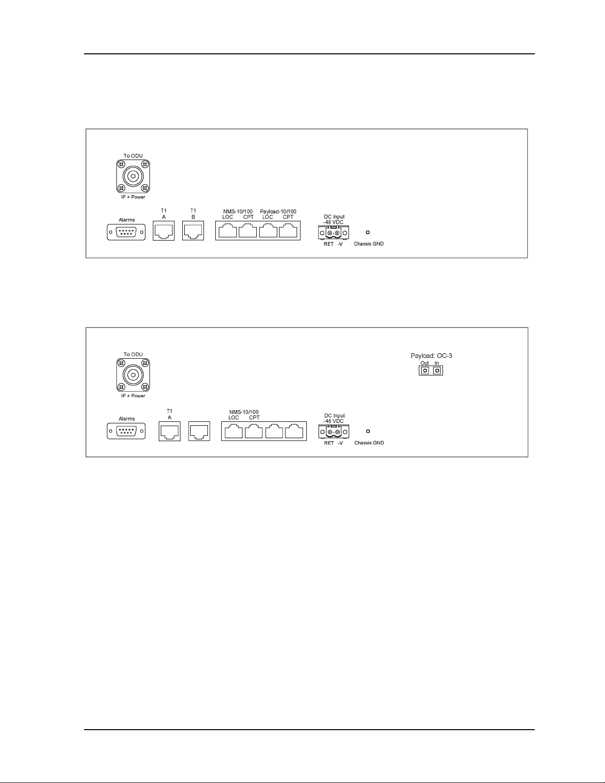
2.4.3 Rear Panel Connections
Please refer to the Figures 2-4 and 2-5 for a pictorial of the CarrierWave IDU rear panel followed
by a descriptive text of the connections.
Figure 2-4. CarrierWave-100 Ethernet: IDU Rear Panel Connections
Figure 2-5. CarrierWave-155 SONET: IDU Rear Panel Connections
The recommended maximum length for all cables to terminal equipment is a maximum of 3
meters. The exception to this recommendation is the length of the ODU/IDU Interconnect cable,
which connects the Outdoor Unit to the Indoor Unit.
MK-MAN-01 CarrierWave Digital Radio
Page 15
User Reference and Installation Manual 2-9
Power Supply
DC Input
-48 VDC
-48v (Isolated Input); 2-pin captive power connector. The
CarrierWave Digital Radio requires an input of –37 to –60 volts
dc at the rear panel DC Input connector. The total required
power is a maximum of 70 W. The IDU rear panel power
connector pin numbering is 1 through 2, from left to right,
when facing the unit rear panel. Pin 1 is the power supply
return and is connected to unit chassis ground internally. Pin
2 should be supplied with a nominal –48 V dc, with respect to
the unit chassis (ground). A ground-isolated supply may be
used, provided it will tolerate grounding of its most positive
output.
The recommended power input is –44 to –52 V dc at 2 Amps
minimum. It is recommended that any power supply used be
able to supply a minimum of 100 W to the IDU.
A mating power cable connector is supplied with the
CarrierWave IDU. It is a 2-pin plug, 5 mm pitch, manufactured
by Phoenix Contact, P/N 17 86 83 1 (connector type MSTB
2,5/2-STF). This connector has screw clamp terminals that
accommodate 24 AWG to 12 AWG wire. The power cable
wire should be selected to provide the appropriate current with
minimal voltage drop, based on the power supply voltage and
length of cable required. The recommended wire size for
power cables under 10 feet in length supplying –48 Vdc is 18
AWG.
Chassis Ground
Chassis GND Chassis ground stud.
Alarm Output Interface
Alarms DB-9 female connector for two Form-C relay alarm outputs
The IDU supplies the ODU with all required power via the
ODU/IDU Interconnect cable. The CarrierWave Digital Radio
IDU does not have a power on/off switch. When DC power is
connected to the IDU, the digital radio powers up and is
operational. There can be up to 200 mW of RF power present
at the antenna port (external antenna version). The antenna
should be directed safely when power is applied.
(rated load: 1A @ 30 VDC).
CarrierWave Digital Radio MK-MAN-01
Page 16

2-10 System Description
CarrierWave-100/Ethernet Models: Ethernet 100BaseT Connection
100BaseTX
LOC
100BaseT
CPT
CarrierWave-155/SONET Models: OC-3 Connection
OC-3 Out OC-3 type SC connectors for the OC-3 interface.
OC-3 In OC-3 type SC connectors for the OC-3 interface.
ODU/IDU Interconnect
To ODU N-type female connector. Used to connect the ODU to the
NMS 10/100 Network Management System Connection
10/100BaseT
LOC
100Base-TX RJ-45 modular port connector for the local Fast
Ethernet interface.
100Base-TX RJ-45 modular port connector. This port to be
used for consecutive point networks.
IDU. Provides –48VDC and 2375 MHz Transmit IF to the
ODU and receives 1675 MHz Receive IF from the ODU.
10/100Base-TX RJ-45 modular local port connector for access
to the CarrierWave Network Management System (SNMP or
iConductor, a CarrierWave proprietary system).
10/100BaseT
CPT
T1 Wayside Channels
T1 – A Wayside channel for T1 (RJ-48C) interface voice connection.
T1 – B Wayside channel for T1 (RJ-48C) interface voice connection.
10/100BaseTX RJ-45 modular remote port connector for
access to the CarrierWave port Network Management System
(SNMP or iConductor, a CarrierWave proprietary system).
This port to be used for consecutive point networks.
Operational for both CarrierWave-100 Ethernet and
CarrierWave-155 SONET models.
B channel option only available in CarrierWave-100 Ethernet
model.
2.5 System Description
The overall digital radio architecture consists of a single 2RU rack mount Indoor Unit (IDU) with a
cable connecting to an Outdoor Unit (ODU) with an integrated antenna. There is an option for
interfacing the ODU with an external antenna (consult factory for this option). This IDU/ODU
architecture is advantageous when compared to a single IDU with external mount antenna since
supporting a signal of 5.8 GHz from the IDU rack to the antenna will experience significant signal
degradation requiring expensive coaxial cable or waveguide.
MK-MAN-01 CarrierWave Digital Radio
Page 17
User Reference and Installation Manual 2-11
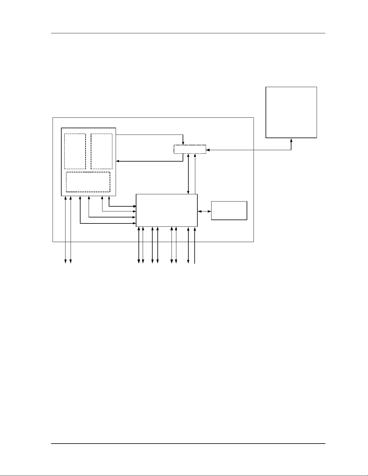
Figure 2-6 shows a functional block diagram of the CarrierWave Digital Radio, which consists of
an antenna, ODU RF Up/Down Converter with HPA and LNA, IF Processor, 64-QAM Modem,
Multiplexer/Demultiplexer, and IDU Front Panel.
ODU
5.8 GHz Radio with
Integrated 23 dBi
IDU
2375 MHz
Antenna
64-QAM
Modem
2 x OC-3 2 x 100BaseT
IF Processor
Framer
3.3V, 5V, 6V,-12V
Note: OC-3 only available
on SONET IDUs and
100BaseT only available
on Ethernet IDUs. Single
T1 supported on SONET
IDUs
1675 MHz
Control
SNMP
Payload
Figure 2-6. CarrierWave System Block Diagram
IDU/ODU
Comm Link
Multiplexer/Demultiplexer
Ethernet Scaler
2 x 10BaseT
SNMP
2 x T1
MUX
RS232
Control
48 V
Power (48 Vdc)
Front Panel
(Display)
2375 MHz
1675 MHz
Radio
Control/Status
ODU Power
The IDU interfaces with the ODU to receive and provide modulated transmit and receive
waveforms. The IDU interfaces provide SONET OC-3 (CarrierWave-155) and Fast Ethernet
100Base-T (CarrierWave-100) connections to the network. In addition, one (SONET model) or
two (Ethernet model) T1 channels are provided for PBX extension. SNMP is provided on
10/100BaseT ports.
The ODU RF Up/Down Converter card provides the interface to the antenna. The transmit
section up converts and amplifies the modulated Intermediate Frequency (IF) of 2.375 GHz from
the IF Processor and provides additional filtering. The receive section down converts the
received signal, provides additional filtering, and outputs an IF of 1.675 GHz to the IF Processor.
The 64-QAM Modem performs the modulation and demodulation of the payload (OC-3 or Fast
Ethernet or Scalable Ethernet), and forward error correction using advanced modulation and
coding techniques. Using all-digital processing, the 64-QAM Modem uses robust modulation and
forward error correction coding to minimize the number of bit errors and optimize the radio and
network performance. The 64-QAM Modem also scrambles, descrambles and
CarrierWave Digital Radio MK-MAN-01
Page 18

2-12 System Description
interleaves/deinterleaves the data stream in accordance with Intelsat standards to ensure
modulation efficiency and resilience to sustained burst errors. The modulation will vary by
application, data rate, and frequency spectrum. The highest order modulation mode supported is
64 Quadrature Amplitude Modulation (QAM). Table 2-4 summarizes the TCM/convolutional code
rates for each modulation type supported by the Digital Radio.
Table 2-4. CarrierWave Digital Radio TCM/Convolutional Code Rates
Modulation Type Available Code
Rates
QPSK ½, 3/4, 7/8, 1/1
16-QAM ¾, 7/8, 11/12
32-QAM 4/5, 9/10
64-QAM 5/6, 11/12
The IDU also provides the physical interface for the user payload and network management. In
transmit mode, the Framer merges user payload (OC-3 or Fast Ethernet) with radio overheadencapsulated network management data. This combined data stream is transmitted without any
loss of user bandwidth. In the receive mode, the Framer separates the combined data stream
received from the 64-QAM Modem. The IDU supports Scalable Ethernet data rates, such as 25
or 50 Mbps via the 100BaseT data interface port. The IDU provides network management data
on 10 Mbps ports accessible via the 10/100BaseTX port. The Central Processor Unit (CPU)
provides the embedded control and network element functionality of the OAM&P. The CPU also
communicates with other functions within the IDU for configuration, control, and status
monitoring. The CPU passes appropriate status information to the IDU front panel display.
The power supply converts 48 Vdc to the DC voltage levels required by each component in the
system.
2.6 Consecutive Point Architecture
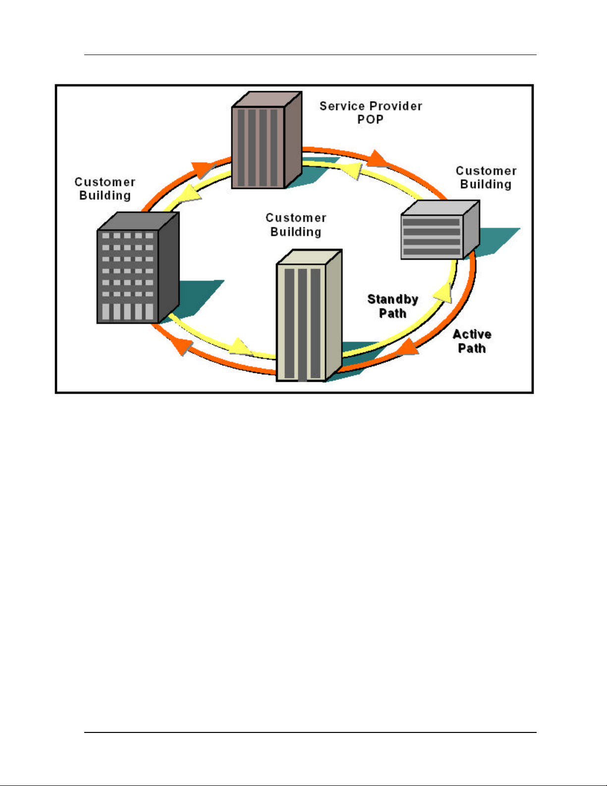
The consecutive point network architecture is based upon the proven SONET/SDH ring.
Telecommunications service providers traditionally use the SONET/SDH ring architecture to
implement their access networks. A typical SONET/SDH network consists of the service
provider’s Point of Presence (POP) site and several customer sites with fiber optic cables
connecting these sites in a ring configuration (see Figure 2-7). This architecture lets providers
deliver high bandwidth with high availability to their customers.
MK-MAN-01 CarrierWave Digital Radio
Page 19
User Reference and Installation Manual 2-13
Figure 2-7. Ring Configuration.
SONET/SDH rings are inherently self-healing. Each ring has both an active path and a standby
path. Network traffic normally uses the active path. Should one section of the ring fail, the network
will switch to the standby path. Switchover occurs in seconds. There may be a brief delay in
service, but no loss of payload, thus maintaining high levels of network availability.
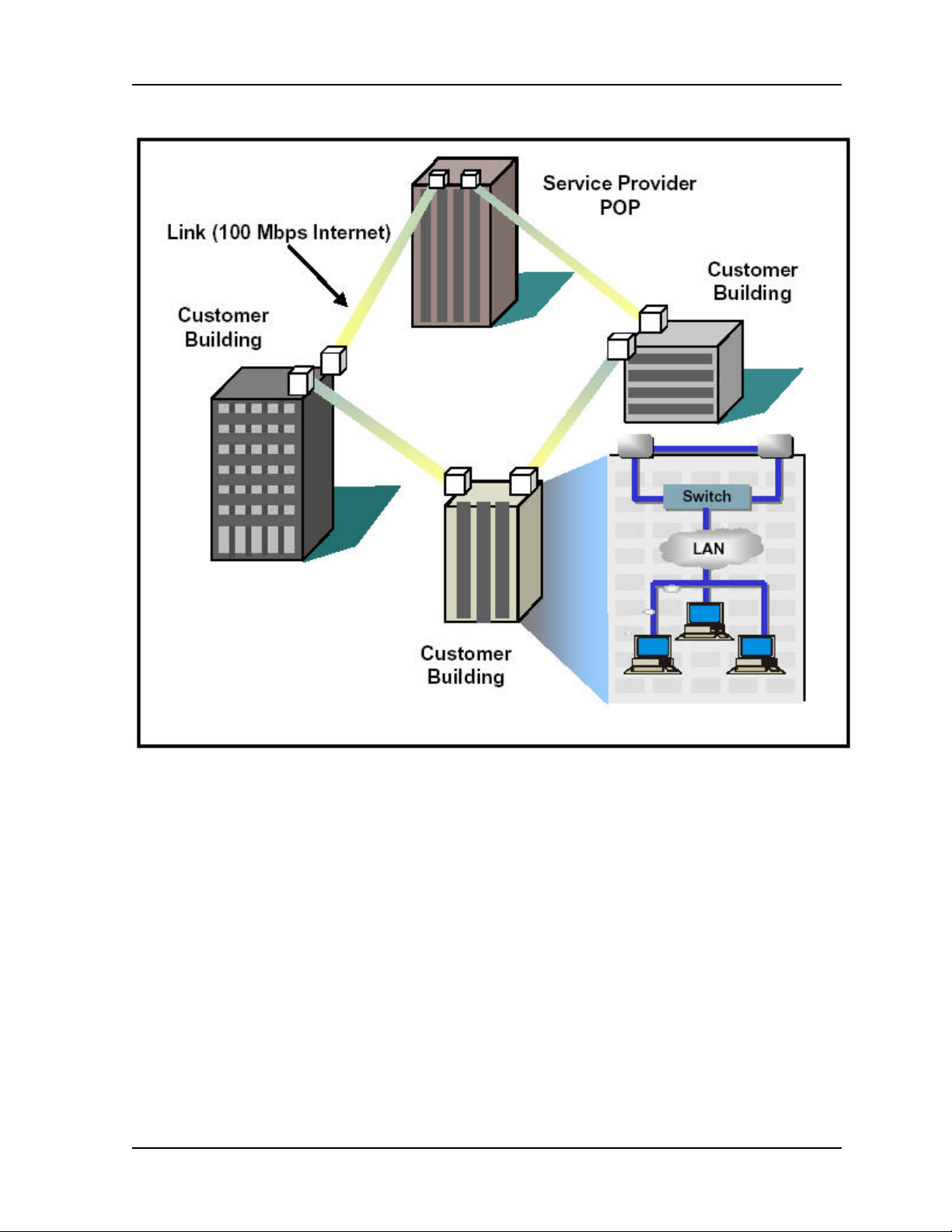
The consecutive point architecture implemented in the CarrierWave Digital Radio family is based
on a point-to-point-to-point topology that mimics fiber rings, with broadband wireless links
replacing in-ground fiber cable. A typical consecutive point network consists of a POP and
several customer sites connected using CarrierWave units. These units are typically installed in
pairs in a building. Each unit installed at a customer site is logically connected to two other units.
These connections are as follows:
• An over-the-air radio frequency (RF) link to a unit at an adjacent site
• A back-to-back Ethernet cable link to another unit in the same building through a switch
Each consecutive point network typically starts and ends at a POP. A pattern of wireless links and
in-building connections is repeated at each site until all buildings in the network are connected in
a ring as shown in Figure 2-8.
CarrierWave Digital Radio MK-MAN-01
Page 20
2-14 System Description
Figure 2-8. Consecutive Point Network
MK-MAN-01 CarrierWave Digital Radio
Page 21

User Reference and Installation Manual 2-15
2.7 Power Management
RF power management is a radio design feature that controls the power level (typically expressed
in dBm) of the RF signal received from a transmitter by a receiver. The traditional goal of power
management is to ensure that the RF signal at a receiver is strong enough to maintain the radio
link under changing weather and link conditions.
Traditional power management techniques such as Constant Transmit Power Control (CTPC)
and Automatic Transmit Power Control (ATPC) transmit at a high power level to overcome the
effects of fading and interference. However, these techniques continue to operate at a higher
power level than needed to maintain the link in clear weather. Because transmit power remains
high when the weather clears, the level of system interference increases.
Radios operating at high transmit power will interfere with other radios, even if the interfering
source is miles away from the victim. High interference levels can degrade signal quality to the
point that wireless radio links become unreliable and network availability suffers. The traditional
solution to system interference is to increase the distance between radios. However, the resulting
sparse deployment model is inappropriate for metropolitan areas.
In response to the need for a high-density deployment model the CarrierWave use a unique
power control technique called AdTPC. AdTPC enables CarrierWave units to transmit at the
minimum power level necessary to maintain a link regardless of the prevailing weather and
interference conditions. The CarrierWave is designed and manufactured to not exceed the +30
dBm maximum power allowed. The purpose of power management is to minimize transmit power
level when lower power levels are sufficient. AdTPC also extends the concept of power
management by controlling not only the power (dBm) of the RF signal, but its quality (signal-tonoise ratio) as well.
In contrast to ATPC, the AdTPC technique dynamically adjusts the output power based on both
the actual strength and quality of the signal. Networked CarrierWave units constantly monitor
receive power and maintain 10
conditions. Each CarrierWave unit can detect when there is a degradation in the received signal
level of quality and adjust the transmit power level of the far-end CarrierWave unit to correct for it.
AdTPC provides maximum power in periods of heavy interference and fading and minimum power
when conditions are clear. Minimal transmit power reduces potential for co-channel and adjacent
channel interference with other RF devices in the service area, thereby ensuring maximum
frequency re-use. The resulting benefit is that operators are able to deploy more CarrierWave
units in a smaller area.
-12
BER performance under varying interference and climate
CarrierWave Digital Radio MK-MAN-01
Page 22

2-16 System Description
2.8 CarrierWave iWareTM Software and Network
Management
iWareTM is the software suite that is fully compatible with SNMP (v1) and standard NMS software.
All of the CarrierWave Digital Radio parameters are accessible through the fully featured MIB,
allowing for automation of data collection and network management.
iWareTM includes:
• iPorterTM: capability to remotely manage the software. It enables the user to install, backup
and recover CarrierWave Digital Radio software
• iConductorTM: a GUI-based management application that can be run locally, at the installation
site, from a PC connected directly to the CarrierWave IDU, or it may be operated remotely
from any from any point in a CarrierWave network.
Detailed descriptions of iWareTM are provided in a separate document.
MK-MAN-01 CarrierWave Digital Radio
Page 23
3 Installation
3.1 Unpacking
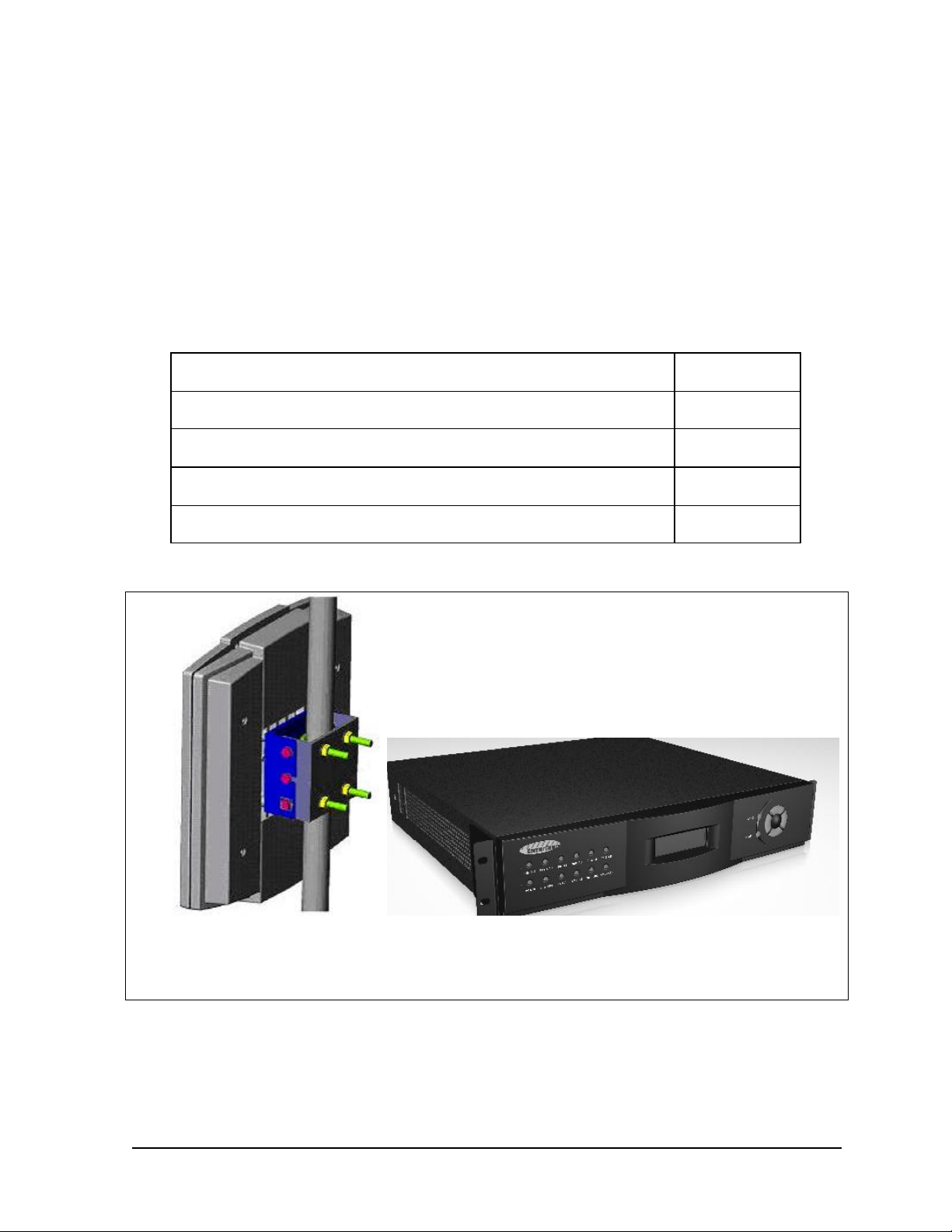
The following is a list of all included items.
Description Quantity
Digital Radio IDU (2RU chassis) 1
ODU (with hardware) 1
Manual (or Soft copy on a CD) 1
Test Data Sheet (customer documentation) 1
IDUODU
Figure 3-1. CarrierWave Digital Radio Components
Be sure to retain the original boxes and packing material in case of return shipping. Inspect all
items for damage and/or loose parts. Contact the shipping company immediately if anything
CarrierWave Digital Radio MK-MAN-01
Page 24

3-2 Installation
appears damaged. If any of the listed parts are missing, call the distributor or the factory
immediately to resolve the problem.
3.2 Notices
CAUTION
IF USING EXTERNAL ANTENNA OPTION (SEE FACTORY FOR DETAILS), DO NOT
OPERATE UNITS WITHOUT AN ANTENNA, ATTENUATOR, OR LOAD CONNECTED TO THE
ANTENNA PORT. DAMAGE MAY OCCUR TO THE TRANSMITTER DUE TO EXCESSIVE
REFLECTED RF ENERGY.
ALWAYS ATTENUATE THE SIGNAL INTO THE RECEIVER ANTENNA PORT TO LESS THAN
–20 dBm. THIS WILL PREVENT OVERLOAD AND POSSIBLE DAMAGE TO THE RECEIVER
MODULE.
WARNING
HIGH VOLTAGE IS PRESENT INSIDE THE ODU and IDU WHEN THE UNIT IS PLUGGED IN.
TO PREVENT ELECTRICAL SHOCK, UNPLUG THE POWER CABLE BEFORE SERVICING.
UNIT SHOULD BE SERVICED BY QUALIFIED PERSONNEL ONLY.
3.3 PRE-INSTALLATION NOTES
It may be useful to gain familiarity with the CarrierWave Digital Radio via back-to-back bench
testing prior to final installation. We highly recommend installation of lightning protectors on the
ODU/IDU Interconnect Cable to prevent line surges from damaging expensive components.
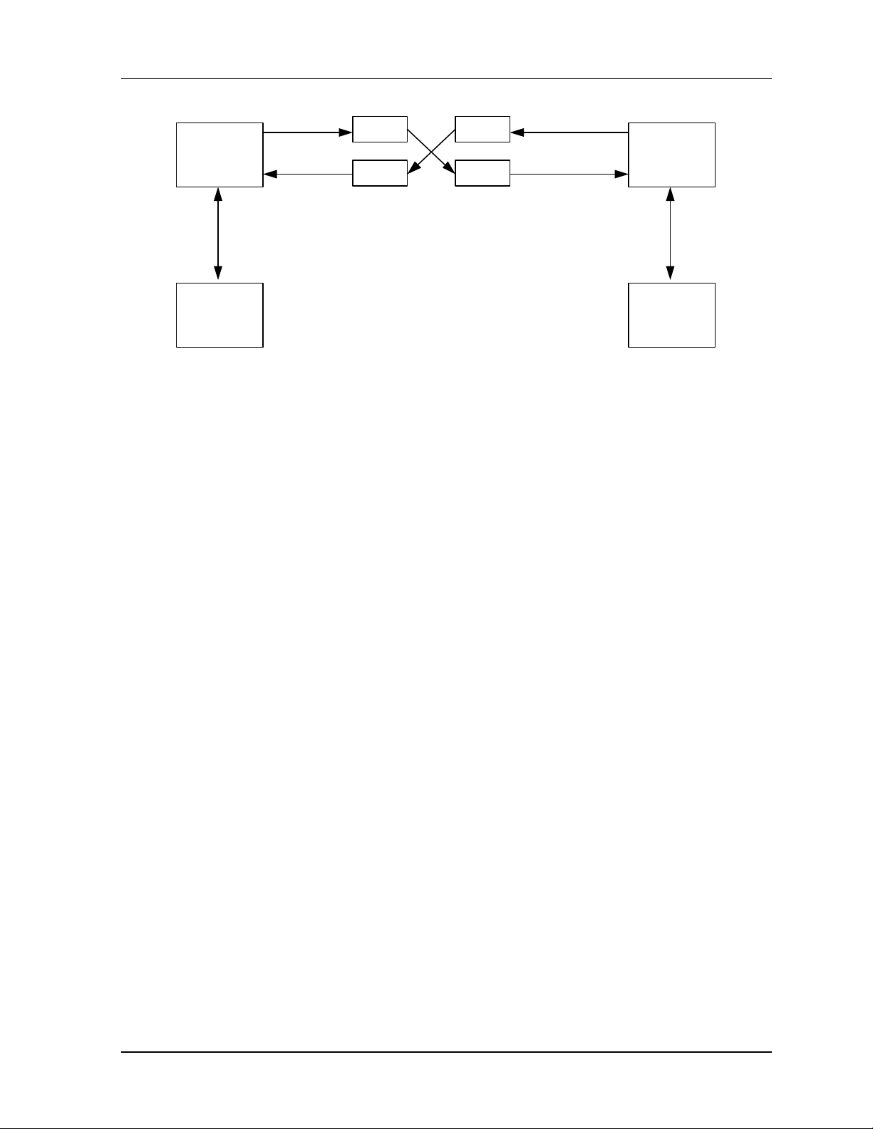
3.3.1 Back-to-Back Bench Testing
Back-to-back bench testing prior to final installation is highly recommended in order to gain
familiarity with the product. This test requires external antenna support. The following additional
equipment is required for back-to-back testing:
• Low-loss cables, N-male connectors on ODU interfaces.
• Four Inline RF attenuators, 40 dB each (or replace two with single 80 dB attenuator), rated for
5.8 GHz.
The IDU and ODUs must be configured in an operational configuration and set-up as shown in
Figure 3-2. When equipment is connected in operational configuration, no errors should be
reported on the front panel.
MK-MAN-01 CarrierWave Digital Radio
Page 25
User Reference and Installation Manual 3-3
Ext Ant Tx
- 40 dB
- 40 dB
ODU - 1
Ext Ant Rx
To IDU
- 40 dB - 40 dB
IDU - 1
Figure 3-2. CarrierWave Digital Radio Back-to-Back Testing Configuration
Ext Ant Tx
ODU - 2
Ext Ant Rx
IDU - 2
3.4 Overview of Installation and Testing
Process
The installation and testing process is accomplished by performing a series of separate, yet
interrelated, procedures, each of which is required for the successful implementation of a
production CarrierWave Digital Radio network. These procedures are as follows:
• Site Evaluation: gathering specific information about potential CarrierWave Digital Radio
installation sites.
• Cable and Installation: Testing and installing CarrierWave ODU cables and optional interface
devices at installation sites.
• CarrierWave ODU Mounting and Alignment: Mounting ODUs to a pole or wall, performing link
alignment and radio frequency (RF) verification.
• CarrierWave Digital Radio Configuration: Using CarrierWave Link Manager software to install
network- and site-specific parameters in the radios.
• CarrierWave Digital Radio Testing: Performing cable continuity checks and RF tests for links,
the payload/radio overhead channel, and the management channel.
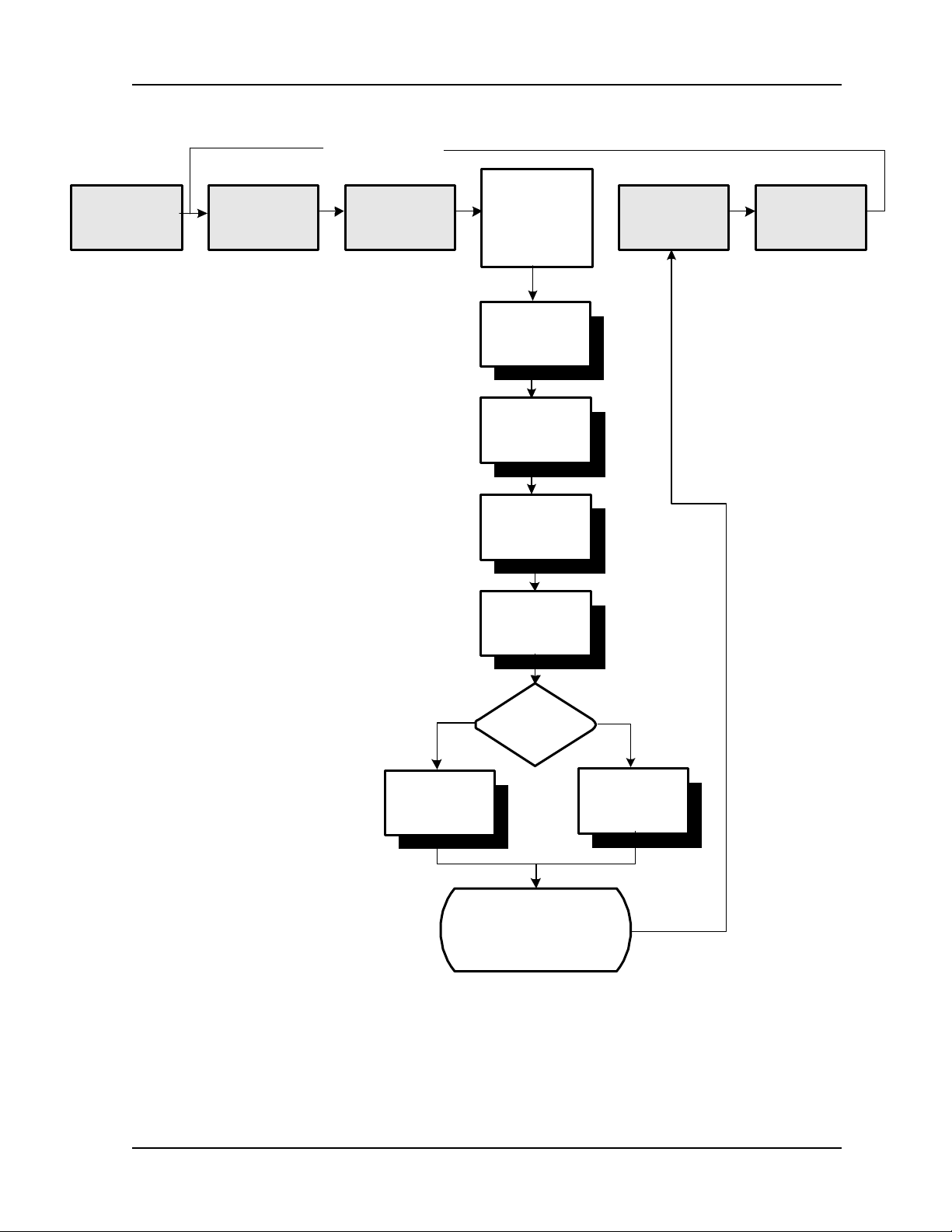
The following diagram shows where installation and commissioning resides within the
CarrierWave Digital Radio network deployment life cycle and defines the sequence in which the
processes that comprise installation and commissioning should be performed.
CarrierWave Digital Radio MK-MAN-01
Page 26
3-4 Installation
Network Life Cycle
Customer
Requirements
RF Planning
& Network
Design
Site Selection
& Acquisition
Installation &
Commissioning
Perform Site
Evaluation
Mount and Align
ODUs
Install Cables
Configure Digital
Radio IDU
Network
Operation &
Maintenance
Network
Upgrade &
Expansion
Ethernet SONET
Perform Fast
Ethernet Test
Type of
Network?
Perform
SONET/SDH
Test
Installation &
Commissioning
Complete
03-01-013a
MK-MAN-01 CarrierWave Digital Radio
Page 27

User Reference and Installation Manual 3-5
3.5 Site Evaluation
A site evaluation consists of a series of procedures for gathering specific information about
potential CarrierWave Digital Radio locations. This information is critical to the successful design
and deployment of a network.
Site evaluations are required to confirm whether or not a building meets network design
requirements. The main objectives are as follows:
• Confirm
• Line of sight for each link
• CarrierWave Digital Radio ODU mounting locations
• Site equipment locations
• Cable routes
• Any other potential RF sources
• Prepare site drawings and record site information
3.5.1 Preparing for a Site Evaluation
The following tools are required to perform a site evaluation:
• RF and network design diagrams (as required)
• Binoculars
• Global positioning system (GPS) or range finder
• Compass
• Measuring tape and/or wheel
• Digital camera
• Area map
• Aerial photograph (if available)
• List of potential installation sites (“targeted buildings”)
The following tasks must be completed prior to performing a site evaluation:
• Prepare the initial network design by performing the following:
CarrierWave Digital Radio MK-MAN-01
Page 28

3-6 Installation
• Identify potential buildings by identifying targeted customers (applicable if you’re a service
provider)
• Identify potential links by selecting buildings based on the high probability of line of sight
• Arrange for access with the facility personnel into the buildings, equipment rooms, and
architectural plans to become familiar with the location of all ducts, risers, etc.
3.5.2 Site Evaluation Process
The following steps must be completed to perform a successful site evaluation. Each step in the
process is detailed in the following subparagraphs:
• Ensure RF Safety compliance: Ensure that appropriate warning signs are properly placed and
posted at the equipment site or access entry. For a complete list of warnings, refer the Safety
Precautions listed at the beginning of this manual.
• Ensure Compliance with Laws, Regulations, Codes, and Agreements: Ensure that any
installation performed as a result of the site evaluation is in full compliance with applicable
federal and local laws, regulations, electrical codes, building codes, and fire codes.
• Establish Line of Sight between CarrierWave Digital Radios: The most critical step in
conducting a site evaluation is confirming clear Line of Sight (LOS) between a near
CarrierWave Digital Radio and a far CarrierWave Digital Radio. If LOS does not exist,
another location must be used.
CarrierWave Radios in a link must have a clear view of each other, or “line of sight”.
Binoculars may be used evaluate the path from the desired location of the near CarrierWave
Radio to the desired location of the far CarrierWave Radio.
To confirm Line of Sight:
- Ensure that no obstructions are close to the transmitting/receiving path. Take into
consideration trees, bridges, construction of new buildings, unexpected aerial traffic,
window washing units, etc.
- Ensure that each CarrierWave Digital Radio can be mounted in the position required to
correctly align the CarrierWave Digital Radio with its link partner.
• Determine CarrierWave ODU Mounting Requirements: CarrierWave ODUs can be mounted
on an antenna mast, brick, masonry or wall. Refer to detailed installation sections.
• Determine CarrierWave IDU Installation Location: CarrierWave IDUs can be installed tabletop
or cabinet, wall mount, or rack mount. The site must provide DC power. Refer to detailed
installation sections.
• Document Potential Sources of Colocation Interference: When CarrierWave ODUs are
located on a roof or pole with other transmitters and receivers, an interference analysis may
be required to determine and resolve potential interference issues. The interference analysis
needs to be performed by an RF engineer. The specific information required for each
transmitter and receiver includes the following:
MK-MAN-01 CarrierWave Digital Radio
Page 29

User Reference and Installation Manual 3-7
- Transmitting and/or receiving frequency
- Type of antenna
- Distance from CarrierWave ODU (horizontal and vertical)
- Polarity (horizontal or vertical)
- Transmit power level
- Antenna direction
• Measure the Link Distance: The two ways to measure link distance are as follows:
- GPS: record the latitude and longitude for the near and far CarrierWave ODU sites and
calculate the link distance. Record the mapping datum used by the GPS unit and ensure
the same mapping datum is used for all site evaluations in a given network.
- Range finder: measure the link distance (imperial or metric units may be used).
Once the link distance has been measured, verify that the link distance meets the availability
requirements of the link.
• Select the Grounding Location for both the CarrierWave ODU and IDU: The CarrierWave
Digital Radio must be properly grounded in order to protect it and the structure it is installed
on from lightning damage. This requires
- Grounding all ODUs as specified in the Installation section
- Grounding all IDUs to the rack.
• Determine the Length of Interconnect Cable from ODU to IDU: The primary consideration for
the outdoor interconnect cable from the ODU to IDU is the distance and route between the
ODU and IDU. This cable should not exceed 300 feet using Times Microwave LMR-400
cable. Longer lengths and distances are possible, but require higher quality cable, as
illustrated in the table below.
Cable Type Loss at 2.5 GHz
(dB/100 ft.)
Cable Length
Allowed (ft.)
LMR-200 16.9 120
LMR-300 10.4 200
LMR-400 6.8 300
LMR-600 4.4 450
LMR-900 3.0 650
Listed cable types are from Times Microwave, equivalent cable
from other manufacturers may be used
CarrierWave Digital Radio MK-MAN-01
Page 30

3-8 Installation
• Confirm the Presence of DC Power for the CarrierWave IDU.
• Ensure Building Aesthetics: The CarrierWave ODU’s streamlined exterior is designed to
complement building aesthetics. Ensure that the ODU can be mounted so that it is
aesthetically pleasing to the environment and to the property owner. Aesthetics must be
approved by the property owner and the network engineer.
• Take Site Photographs
• Sketch the Site
3.5.3 Critical System Calculations
3.5.3.1 Received Signal Level (RSL) and Link Budget
The received signal level (RSL) can be estimated using the following formula:
RSL (dBm) = PTX + G
TX ANT
– L
Path
+ G
RX ANT
Where: PTX is the transmitter output power (in dBm)
G
G
L
is the Path loss, defined by:
Path
L
(dB) = 36.6 + 20log10(F*D)
P
is the gain of the transmit antenna (in dB), 23 dBi for ODU’s internal antenna
TX ANT
is the gain of the receive antenna (in dB), 23 dBi for ODU’s internal antenna
RX ANT
Where: F is the Frequency in MHz (5800), D is the Distance of path in miles
This link budget is very important in determining any potential problems during installation. The
expected RSL and measure RSL should be close (+/- 5 to 10 dB)
3.5.3.2 Fade Margin Calculation
The fade margin is the difference between the actual received signal and the CarrierWave Digital
Radio’s threshold for the modulation mode selected. The fade margin can be used to determine
availability and should be at least 10 dB.
3.5.3.3 Availability Calculation
Availability of the microwave path is a prediction of the percent of time that the link will operate
without producing an excessive BER due to multipath fading. Availability is affected by the
following:
• Path length
• Fade margin
MK-MAN-01 CarrierWave Digital Radio
Page 31

User Reference and Installation Manual 3-9
• Frequency
• Terrain (smooth, average, mountainous, valleys)
• Climate (dry, temperate, hot, humid)
Depending on the type of traffic carried over the link and the overall network design redundancy,
fade margin should be included to support the desired availability rate. Critical data and voice
may require a very high availability rate (99.999% or 5.3 minutes of predicted outage per year).
To improve availability, the fade margin can be increased by shortening the path length,
transmitting at a higher power level, or by using higher gain antennas.
Availability can be computed using the following formula, which is known as the Vigants Barnett
Method.
Availability = 100 × (1 – P)
3
P = 2.5 × 10⁻⁹ × C × F × D
× 10
(-FM/10)
Where F is the frequency in MHz (5800)
D is the distance in miles
FM is the fade margin in dB
C is the climate/terrain factor as defined below:
Humid/Over Water: C = 4 (worst case channel)
Average Conditions: C = 1
Dry/Mountains: C = 0.25 (best case channel)
Example: Assume 21 dB fade margin, over 5 miles with average climate/terrain. The availability
comes out to be 99.9986. This corresponds to the link being unavailable for 7.6 minutes per
year.
3.5.3.4 Frequency Plan Determination
When configuring CarrierWave Digital Radios in a point-to-point or consecutive point
configuration, careful engineering of the CarrierWave Digital Radio frequency plans and antenna
locations should be performed in order to minimize potential interference between nearby radios.
Nearby radios should operate on different frequencies, transmitting in the same band (high side
or low side). When designing multi-radio configurations, antenna size, antenna polarization, and
antenna location are critical.
The frequency plan must be selected based on desired data rate and expected link conditions. In
a high interference environment or with lower gain antennas, higher bandwidth, more robust
modulation formats must be employed. The available frequency plans are illustrated in Figure 3-
3.
CarrierWave Digital Radio MK-MAN-01
Page 32

3-10 Installation
1 Channel Operation
A Tx
B Rx
5725
1A Tx
1B Rx
5725
5725
5725
5737.5
1A Tx
1B Rx
5733.3 5841.7
1A Tx
1B Rx
5731.3
5750 5825
2A Tx
2B Rx
5762.5
2A Tx
2B Rx
5750
2A Tx
2B Rx
5743.7 5768.7
3A Tx
3B Rx
5753.3
3A Tx
3B Rx
5766.7
4A Tx
4B Rx
Duplexer
2 Channel Operation
Duplexer
3 Channel Operation
Duplexer
4 Channel Operation
Duplexer
1A Rx
1B Tx
5812.5
1A Rx
1B Tx
5808.3
1A Rx
1B Tx
5806.3
A Rx
B Tx
2A Rx
2B Tx
5825
2A Rx
2B Tx
5818.7 5831.3
3A Rx
3B Tx
2A Rx
2B Tx
5837.5
3A Rx
3B Tx
4A Rx
4B Tx
5843.7
F, MHz
5850
F, MHz
5850
F, MHz
5850
F, MHz
5850
Figure 3-3. CarrierWave Digital Radio Channel Frequency Plans
3.5.3.5 Antenna Planning
The ODU comes with a built in 23 dBi gain antenna. This should provide adequate link
performance for most applications.
Larger antennas have the advantage of providing narrower beamwidths and high isotropic gain,
which yields better link performance (higher fade margin, better availability), and improves
immunity to spatial interference (due to the smaller beamwidths). However, larger antennas are
more costly to purchase and install than smaller antennas and in some cases, they require
special equipment for installation due to narrower beamwidths. They are also more easily
affected by wind.
Only directional antennas can be used with the CarrierWave Digital Radios. Consult factory for
antenna manufacturer options.
MK-MAN-01 CarrierWave Digital Radio
Page 33

User Reference and Installation Manual 3-11
The ISM band does not restrict antenna gain or EIRP, therefore there is no need to back off
transmit power due to excessive antenna gain.
1. Select where the cable will enter the building from the outside.
2. Determine the length of cable required. Allow three extra feet on each end to allow for strain
relief, as well as any bends and turns.
3.5.4 Documenting a Site Evaluation
Use the site evaluation form provided on the following pages to document the results of your site
evaluation. Optimally, this complete site form would be stored with the IDU for future reference.
CarrierWave Digital Radio MK-MAN-01
Page 34

3-12 Installation
Site Evaluation Form
Address Site Engineer
Contact Person
Phone
Site No Site Agent
Site Type
ODU Roof Location
# Latitude Longitude
Mapping Datum (ex. NDA27)
ODU
Example Information Information Information
ODU# 4
Clear Line of Sight Yes
Mounting Method Wall or Pole
FCC Compliance Yes
Collocation
Aesthetics
ODU Azimuth 60 degrees
GPS Reading 80 21' 48"
Cable Lengths
Alarm
Interconnect Cable 250 feet
Grounding/Lighting
Instructions
Photographs*
Photo 1
Photo 2
Roof Requirements
Photo 3
Sketches**
Sketch 1
Sketch 2
Recommendations for Site Photographs and Sketches
*Photographs **Sketches
Photo 1 - ODU mounting location Sketch 1- Roof and cable route to entry point
Phone 2 - View from the ODU mounting location to the link partner Sketch 2 - Details for grounding and lighting protection
Photo 3 - IDU location Sketch 3 - IDU room and cable routes from entry port
MK-MAN-01 CarrierWave Digital Radio
Page 35

User Reference and Installation Manual 3-13
Site Evaluation Form
Indoor Space Requirements
Parameters Example Information Information Information Information
Source PCS
Tx and/or Rx Tx/Rx
Frequency 2.1 GHz
Distance from ODU 5 feet
Owner Sprint PCS
Azimuth 210 degrees
Elevation 2 degrees downtilt
Antenna Type
Power
Colocated AntennaIDU
Power 14W
Parameters Example Information Information Information Information
IDU room Identified Yes
Space for cabinet Yes
Phone line Need to install
48 VDC available? Yes
Cables Confirm cables
Take Photo 3
Sketch 3
Front View Top View Side View
Equipment Dimensions
Equipment Cabinet
Batteries
Notes
CarrierWave Digital Radio MK-MAN-01
Page 36

3-14 Installation
3.6 Installation of the CarrierWave Digital Radio
The following sections provide installation guides for:
• IDU Installation
• ODU Installation
3.6.1 Installing the CarrierWave IDU
The CarrierWave IDU can be installed in the following three options:
1. Table top or cabinet
2. Wall mount
3. Rack mount
The CarrierWave IDU should be:
• Located where you can easily connect to a power supply and any other equipment used in
your network, such as a router or PC.
• In a relatively clean, dust-free environment that allows easy access to the rear panel
connectors as well as the front panel controls and indicators. Air must be able to pass freely
over the chassis.
• Accessible for service and troubleshooting.
• Protected from rain and extremes of temperature (it is designed for indoor use).
3.6.1.1 Installing on a Table Top or Cabinet
The CarrierWave IDU can be placed on a tabletop or cabinet shelf. In order to prevent possible
disruption, it is recommended to use a strap to secure the IDU.
3.6.1.2 Installing on a Wall
An installation option for the IDU is mounting the unit to a wall. Consult factory for details.
If the wall mount option is being considered, plan to position the CarrierWave IDU at a height that
allows LEDs, the display on the front panel, and the rear connectors to be visible at all times and
easily accessible. Also, including plastic clamps to support and arrange the ODU/IDU
Interconnect Cable should also be considered.
3.6.1.3 Installing in a Rack
To maintain good airflow and cooling, it is preferred that the CarrierWave IDU in a slot that has
blank spaces above and below the unit.
MK-MAN-01 CarrierWave Digital Radio
Page 37

User Reference and Installation Manual 3-15
To rack-mount the IDU, use the supplied mounting brackets (CarrierComm part number 823184A01) to secure the chassis to the rack cabinet. As shown in Figure 3-4, the brackets can be
attached at any of four points on the sides of the enclosure – front, back, middle facing front, and
middle facing back. This flexibility ensures compatibility with most rack mounting arrangements.
Figure 3-4. CarrierWave IDU Dimensions
3.6.2 Installing the CarrierWave ODU
There are three options for mounting the CarrierWave ODU
• Antenna mast
• Pole
• Building
Each site must be assessed for the mounting method, location, and height. After defining the
mounting location and height for the CarrierWave ODU, re-confirm the line of sight.
CarrierWave Digital Radio MK-MAN-01
Page 38

3-16 Installation
Tools and Equipment required for installation of the ODU:
Tools Required Equipment Required
Compass and protractor ¼ inch grounding rod
Area map Grounding clamp
Phillips-head screwdriver Grounding wire
Flat-head screwdriver Coaxial cable assembly
Hammer or mallet #6 wood screws
Power drill Cable clips
1/8 inch drill bit Anchor sleeves
¼ inch masonry drill bit
5mm hex (Allen) wrench
Bubble level or plumb line
Adjustable wrench
Wire snake (if routing cable through interior walls)
3.6.2.1 Installing the Mounting Poles
First install the mounting poles, on which you will mount the CarrierWave ODU. The mounting
pole J bracket is optional equipment. Consult factory for supply and part number. It is important
to note the direction in which the ODU will point when installing the mounting pole.
The mounting pole must be mounted in a vertical position. Failure to do so may result in
improper alignment of the ODU. If you need to tilt the ODU to avoid self-interference, you should
use a tilt (optional) bracket. Consult factory for tilt bracket.
The mounting pole must be grounded.
3.6.2.1.1 Installing on an Antenna Mast
1. Position the mounting pole on the antenna mast. The mounting pole J-bracket is optional
equipment. Consult factory for supply and part number.
2. Insert the U-bolts around the mast and through the holes in the mounting pole. Install a
washer and nut to each side of the threaded U-bolt and hand tighten. Repeat this step for the
second U-bolt.
MK-MAN-01 CarrierWave Digital Radio
Page 39

User Reference and Installation Manual 3-17
3. Tighten nuts equally until mounting pole is secure and cannot rotate.
Typically 2 ½
inch
Figure 3-5. Optional Mounting Pole J Bracket Installed on Pole or Antenna Mast
3.6.2.1.2 Installing on Brick or Masonry
1. Place the mounting plate against the wall. Use a level or plumb line to set the mounting pole
perpendicular to the ground (J-bracket is optional, consult factory for supply and part
number).
2. Mark the hole locations.
3. Set the pole aside.
4. Drill ¼ inch holes at the marked locations. Drill the holes approximately ½ inch deep.
5. Insert the expansion shields into the drilled holes and tap them home.
6. Align the mounting pole with the drilled holes and fix with the lag bolts.
Figure 3-6. Optional Mounting Pole J Bracket Installation
3.6.2.1.3 Installing on a Wall with Wood Siding
CarrierWave Digital Radio MK-MAN-01
Page 40

3-18 Installation
1. Place the mounting plate against the wall.
2. Using a level, be sure that the mounting pole is perpendicular to the ground (J bracket is
optional. Consult factory for part number and supply). You may need to use spacers, as
shown in Figure 3-7.
3. Mark the hole locations for the drilled hole locations. Remove the mounting pole and set
aside.
4. Drill 1/8-inch holes in the places marked.
5. Use #10 or #12 wood screws to secure the mounting pole to the wall and tighten.
Figure 3-7. Optional Mounting Pole J Bracket on Clapboard Siding
Now that you have installed the mounting pole, you are ready to install the CarrierWave ODU
onto the mounting poles. Reference Figures 3-8 through 3-11.
MK-MAN-01 CarrierWave Digital Radio
Page 41

User Reference and Installation Manual 3-19
Figure 3-8. Mounting Parts for the CarrierWave ODU
2. Place the CarrierWave ODU on the mounting pole.
3. Align the pole clamp with the mounting holes.
4. Insert the mounting screws and hand tighten.
5. Rotate the CarrierWave ODU so it is pointing in the correct direction.
6. Tighten the mounting screws.
Figure 3-9. CarrierWave ODU Rear View
Figure 3-10. Tilt Bracket
CarrierWave Digital Radio MK-MAN-01
Page 42

3-20 Installation
Figure 3-11. CarrierWave ODU with Mounted Tilt Bracket
3.6.3 Routing the ODU/IDU Interconnect Cable
1. Select where the cable will enter the building from outside.
2. Determine the length of cable required. Allow three extra feet on each end to allow for strain
relief, as well as any bends and turns.
3. Route the cable.
The ODU and IDU are equipped with N-type female connectors at their interconnecting ports. A
length of coaxial cable (such as Times Microwave Systems LMR-400, LMR-300 or LMR-200)
fitted with two N-type male connectors is required to connect the ODU to the IDU. This cable
assembly may be supplied in fixed lengths with the digital radio. Bulk coaxial cable of equivalent
specification may also be used, with terminating connectors applied during cable installation.
Based on an evaluation of the cable routing path, pull the ODU/IDU Interconnect cable from one
unit to the other, utilizing cable trays, ducts, or conduit as required. Take care that the ODU/IDU
Interconnect cable is not kinked or damaged in any way during installation. Be sure to protect the
N-type connectors from stress, damage and contamination during installation (do not pull the
cable by the connectors). If multiple ODU/IDU Interconnect cables are to be installed along the
same route, the cables should all be pulled at one time. Be sure the installed cable does not
have any bends that exceed the specified cable bend radius. The ODU/IDU Interconnect cable
should be adequately supported on horizontal runs and should be restrained by hangers or ties
on vertical runs to reduce stress on the cable. Outside the building, support and restrain the
cable as required by routing and environmental conditions (wind, ice).
The CarrierWave ODU/IDU and interconnection must be properly grounded in order to protect it
and the structure it is installed on from lightning damage. This requires that the ODU, any
mounting pole or mast and any exposed interconnect cable be grounded on the outside of the
structure. The IDU must be grounded to a rack or structure ground that also has direct path to
earth ground.
MK-MAN-01 CarrierWave Digital Radio
Page 43

User Reference and Installation Manual 3-21
The ODU must be directly connected to a ground rod or equivalent earth ground. The ODU/IDU
interconnect cable should also be grounded at the ODU, where the cable enters the structure and
at intermediate points if the exposed cable run is long (typically at intervals of 100 ft), with the
cable manufacturer’s grounding kits. Lightning protection devices used with the interconnect
cable must be appropriate for the transmission of the interconnect signals (DC to 2.4 GHz).
Provide a sufficient but not excessive length of cable at each end to allow easy connection to the
ODU and IDU without stress or tension on the cable. Excessive cable length, especially
outdoors, should be avoided to minimize signal attenuation and provide a more robust and
reliable installation. If installing using bulk coaxial cable, terminate the ODU/IDU Interconnect
cable at each end with an N-type male connector appropriate for the cable type. Use of
connectors, tools and termination procedures specified by the cable manufacturer is
recommended.
Once the cable has been installed but before connection has been made to either unit, a simple
DC continuity test should be made to verify the integrity of the installed cable. A DC continuity
tester or digital multimeter may be used verify a lack of DC continuity between the cable center
conductor and outer conductor, with the opposite end of the cable unconnected. With a
temporary test lead or shorting adapter connected to one end of the cable, DC continuity should
be verified between the center and outer conductors at the opposite end.
3.6.3.1 Installing the ODU/IDU Interconnect Cable
1. Screw on the ODU/IDU Interconnect cable with N-type connector.
Figure 3-12. N-type Connector Location – Underside of CarrierWave ODU
2. Insert the N-type connector into the receptacle located underneath the ODU. Make sure that
the connector tab engages the slot in the receptacle.
3. Slide the grommet up the cable and press it into the bottom of the ODU.
3.6.4 Grounding the System
The CarrierWave IDU/ODU System must be properly grounded in order to protect it and the
structure it is installed on from lightning damage. This requires:
1. Grounding all the ODUs as shown in Figure 3-13.
CarrierWave Digital Radio MK-MAN-01
Page 44

3-22 Installation
2. Grounding the IDU to the rack.
3.6.4.1 Grounding the ODU
1. Place the grounding rod so as to allow for the shortest possible path from the grounding cable
to the ODU.
2. Drive the grounding rod into the ground at least eight inches from the ground surface.
3. Attach a grounding clamp to the grounding rod. You will use this clamp to attach grounding
wires for both the ODU and indoor junction box, reference Figure 3-13.
Figure 3-13. Ground Connections to ODU
4. Connect a ground lug to one end of the grounding wire.
5. Remove one of the lower mounting screws of the mounting pole. Insert a screw through the
grounding lug terminal and re-install it to the mounting pole.
6. Attach the grounding wire to the clamp on the grounding rod, reference Figure 3-14. If
necessary, use wire staples to secure the grounding wire to the outside wall.
MK-MAN-01 CarrierWave Digital Radio
Page 45

User Reference and Installation Manual 3-23
Figure 3-14. Mounting Pole with Ground Lug
7. Install a grounding wire from the junction box to the grounding rod.
3.6.4.2 Grounding the IDU
1. Remove the nut and ring lug terminal from the IDU Chassis GND stud.
2. The provided ring lug crimp terminal is intended to be used with 18 AWG wire (provided by
the customer). The IDU should be able to be connected to a system or building electrical
ground point (rack ground or power third-wire ground) with a cable of 36” or less.
3. Crimp the ring lug terminal to one end of the wire to be used as the IDU ground wire.
Connect the opposite end of the IDU ground wire to the local source of ground in an
appropriate manner.
4. Place the ring lug of the IDU ground cable on the IDU Chassis GND stud.
5. Place the nut on the IDU Chassis GND stud and tighten appropriately.
3.7 Configuration of the CarrierWave Digital
Radio
Configuration of the CarrierWave Digital Radio IDU does not require a connection to the ODU. It
is suggested to configure the IDU prior to connecting to the ODU.
3.7.1 Materials Required
The following items are needed to configure an IDU:
• Power supply (-48 V DC @ 2 Amps)
CarrierWave Digital Radio MK-MAN-01
Page 46

3-24 Installation
• IDU power cable
• Digital voltmeter with test leads
• Computer with networking capability, consisting of either:
- Laptop computer with Windows 98/2000/XP operating system, an Ethernet card with any
necessary adapters and a Cat-5 Ethernet crossover cable
or
- Networked computer with Windows 98/2000/XP operating system and an additional
Ethernet cable providing access to the network.
• CarrierWave iConductorTM software
• Site engineering folder with site drawings, or equivalent IDU configuration information
3.7.2 IDU Configuration Process
Using the site attributes identified in the site assessment or equivalent configuration information,
configure each IDU by completing the following procedures:
- Installing CarrierWave iConductor
TM
- Connecting the IDU to the PC and Power Source
- Setting the IDU IP Address
- Configuring the IDU
- Logging Into the IDU Using CarrierWave iConductor
TM
- Configuring the IDU Site Attributes
3.7.2.1 Installing CarrierWave iConductor
TM
If IDU iConductorTM software is not already installed on your PC, perform the following steps:
1. Insert the IDU iConductorTM CD into the CD-ROM drive on your personal computer (PC). Be
sure that the PC has Windows 98/2000/XP software installed.
2. Double click on the My Computer icon located on the desktop.
3. Double click on the CD-ROM drive associated with the computer.
4. Double click on the IC-vX-XX icon, where X-XX is the version of iConductorTM software
appropriate for your unit.
5. Follow the instructions of the installer.
MK-MAN-01 CarrierWave Digital Radio
Page 47

User Reference and Installation Manual 3-25
6. When the installation is complete, test the iConductorTM by going to the Windows Programs>CarrierComm->vX-XX->IC menu (or the appropriate menu or icon) and start the
iConductorTM software.
3.7.2.2 Connecting the IDU to the PC and Power Source
Perform the following steps to ensure the IDU is powered up and connected to you PC:
1. To connect to the IDU DC power connector (located on the IDU rear panel), an IDU power
cable is required. A mating power cable connector (Phoenix Contact P/N 17 86 83 1) is
provided with the CarrierWave IDU for construction of this cable. This connector has screw
clamp terminals that accommodate 24 AWG to 12 AWG wire. The recommended wire size
for construction of power cables under 10 feet in length, supplying –48 V dc, is 18 AWG. The
opposite end of the IDU power cable should have a termination appropriate for the power
supply being used. The IDU power cable should be of sufficient length to avoid tension in the
cable and provide a service loop for connection, but not be of excessive length. Stranded
wire should be used over a solid conductor to reduce tension on the IDU DC Power
connector. Using the supplied power cable connector, pin 2 (labeled -V) should be connected
to the power supply terminal supplying –48 V dc, while pin 1 (labeled RET) should be
connected to the power supply return. Refer to Figure 3-15. Note that pin 1 (RET) of the IDU
DC Power connector is connected to the IDU chassis ground internal to the IDU. Use of a
power supply with an inappropriate ground reference may cause damage to the IDU and / or
the supply.
2. Connect the IDU power cable to the –48 V dc power supply, and place the voltmeter probes
on the unconnected IDU end of the power cable, with the positive voltmeter probe on pin 2
(-V) of the cable connector and the negative probe on pin 1(RET). The connector screw
terminal screw heads may be used as convenient monitor points. Refer to Figure 3-15.
3. Turn on the –48 V dc supply. Verify that the digital voltmeter reads between –44 V dc and –
52 V dc when monitoring the cable points specified above. Adjust the power supply output
voltage and/or change the connections at the power supply to achieve this reading.
4. With the negative voltmeter probe still on pin 1 (RET) of the power cable connector (and the
power supply still on), press the positive voltmeter probe to the IDU chassis and verify a
potential of zero volts between the IDU chassis and cable pin 1 (RET). If the measured
potential is not zero, the power supply may be grounded incorrectly and should not be used in
this condition with an IDU. Note that this measurement assumes that the IDU is installed and
properly grounded. If this is not the case, the same measurement can be made between
cable pin 1 (RET) and a convenient ground (such as an ac outlet third-wire ground).
5. Turn the –48 V dc supply off.
6. Plug the IDU power cable into the IDU rear panel DC Power connector (DC Input). Place the
voltmeter probes on the cable connector screw terminal screw heads as per step 2 above.
Refer to Figure 3-15. Note that the CarrierWave Digital Radio IDU does not have a power
on/off switch. When DC power is connected, the digital radio powers up and is operational.
There can be up to 200 mW of RF power present at the antenna port. The antenna should be
directed safely when power is applied.
7. Turn on the –48 V dc power supply, and verify that the reading on the digital voltmeter is as
specified in step 3 above.
CarrierWave Digital Radio MK-MAN-01
Page 48

3-26 Installation
8. Turn the –48 V dc supply off.
9. Connect the IDU to the laptop computer, using the Cat-5 Ethernet crossover cable or connect
the IDU to a computer network, using a normal Cat-5 Ethernet cable. Connect the Ethernet
cable to OAMP 10/100BaseTX Ch1 connector on the IDU rear panel. Refer to Figure 3-16
for the IDU rear panel connections.
2 1
Figure 3-15. IDU DC Power Cable Connector
Figure 3-16. IDU Rear Panel – CarrierWave-100/Ethernet
3.7.2.3 Setting the IDU IP Address
Use the Front Panel Menu to set the IDU IP address as follows:
1. Power up the IDU and wait for the main menu to appear on the front panel. The menu will be
titled “CarrierWave” and will have several elements, beginning with “Modify Config”.
2. Use the Down arrow key to move the cursor (asterisk or *) three times to scroll it down until it
is aligned with the “Super User” menu item. When the cursor is opposite the Super User
item, press the Enter key.
3. On the Super User menu, move the cursor down and select the “Chg OA&M Params” item.
4. On the “OA&M Params” menu, move the cursor down to the IP: line. Use the right arrow key
to move the cursor into the IP address area. When you see the underline cursor beneath a
character, you can use the up/down keys to change that character. Continue moving back
and forth with the left/right keys and changing the characters as necessary with the up/down
MK-MAN-01 CarrierWave Digital Radio
Page 49

User Reference and Installation Manual 3-27
keys. When the IP address is correct for your network (it must at least be in the same subnet
as the PC you have connected), use the left arrow key to move back to the menu (move left
until there are no flashing underlines).
5. Continue moving down in the “OA&M Params” menu and change the NM: (Netmask)
parameter to be compatible, in the same manner as the IP address. The GW: (gateway) and
FR: (far end) addresses do not need to be changed at this time.
6. When the IP and NM parameters are correct, move the cursor up to the “Save Changes” item
and press the enter key.
7. Use the escape key to back up to the Super User menu, then select the “Reboot IDU” item to
reboot. Press the Enter key to initiate the IDU reboot.
When the reboot process is complete, the IDU should be accessible from your PC.
3.7.2.4 Configuring the IDU
Use the Front Panel Menu to configure the IDU as follows:
1. From the main menu select “Modify Config”.
2. From the Modify Config menu select “Link Params”.
3. On the Link Parameters menu move the cursor to “Mode:” and use the left/right keys to select
from the list of available operating modes.
4. When the correct operating mode is visible, use the Enter key to save it.
5. Move the cursor down to the “Chan:” item and select the proper channel in the same manner.
6. Use the Escape key to back up to the Modify Config” menu and then select the “Adaptive Pwr
Ctrl” menu.
7. Move the cursor to the Start Power item and use left/right keys to select the desired output
power level. When Power Control is off, this will be the fixed output power level.
8. Navigate back up to the Modify Config menu and select the TX Control item.
9. On the TX Control menu, use the left/right arrows to turn the transmitter on or off, and then
use the Enter key to save the setting.
The CarrierWave Digital Radio is now ready for operation (assuming the ODU is connected to the
IDU via the ODU/IDU Interconnect cable (labeled To ODU).
CarrierWave Digital Radio MK-MAN-01
Page 50

3-28 Installation
3.7.2.5 Logging Into the IDU Using CarrierWave iConductor
TM
Use the following procedure to log into an IDU using CarrierWave iConductorTM:
1. On your desktop, click the Start button and select Programs. Then click on the MS-DOS
Prompt icon.
2. In the MS-DOS window, type ping xxx.xxx.xxx.xxx (where xxx.xxx.xxx.xxx represents the IP
address of the IDU) and press enter.
3. If the ping is successful, the following message will appear: Reply from xxx.xxx.xxx.xxx:
bytes=a. time=b ms, TTL=c. Refer to Figure 3-17 for an example of a ping. A successful
ping implies that the IDU and the PC can communicate with one another across an Ethernet
connection.
4. Close the MS-DOS prompt window.
5. Using the Windows Programs->CarrierComm->vX-XX->IC menu (or the appropriate menu or
icon), start up the iConductorTM application.
6. Select the IDU that you wish to login to from the drop-down menu (see Figure 3-18). If there
is not a network element for that IDU, simply select any IDU icon
Note: If there is not an IDU icon, one must be added. To add an IDU icon, use the
Network drop-down menu and select Add. Refer to IDU iConductorTM Online Help at
C:\Program Files\CarrierComm\help\TOC.html for additional information on how to add an
IDU.
7. Use the Network drop-down menu and select Connect (see Figure 3-19). In the IDU
Connect window, complete the following:
• Verify the information in the IP Address field
• Enter engineer in the User ID field
• Enter the password assigned by the System Administrator in the Password field
MK-MAN-01 CarrierWave Digital Radio
Page 51

User Reference and Installation Manual 3-29
8. Click the Connect button to login to the IDU. Login should take less than 30 seconds and the
iConductorTM Workspace window will appear (see Figure 3-20).
Figure 3-17. IDU Ping Example
Figure 3-18. Login IDU Name Insert
CarrierWave Digital Radio MK-MAN-01
Page 52

3-30 Installation
Figure 3-19. Login IDU Connect Screen
Figure 3-20. iConductorTM Workspace Window (Typical) Insert
MK-MAN-01 CarrierWave Digital Radio
Page 53

User Reference and Installation Manual 3-31
3.7.2.6 Configuring the IDU Site Attributes
1. In the iConductorTM Workspace window, select Navigation > Administration > Network to
display the Network Administration window (see Figure 3-21).
2. Select the General tab (bottom tabs) and complete following:
• Enter site information in the Site Name, Site Contact, and Site Location fields as required.
• Click the Set button beside the Installation and/or In-Service fields to automatically generate
the system date and time. If you want to enter a date on your own, enter the date without
selecting set.
Note: If NTP has been defined on the Link Administration window, IDU iConductorTM will use the
time on the NTP server. If you do not have NTP running, IDU iConductorTM accesses the system
time and sets the text field to the value returned by the system clock
3. Click the Save icon to save the data and then select the Network tab (see Figure 3-22).
CarrierWave Digital Radio MK-MAN-01
Page 54

3-32 Installation
Figure 3-21. Network Administration Window (General Tab) Insert
MK-MAN-01 CarrierWave Digital Radio
Page 55

User Reference and Installation Manual 3-33
Figure 3-22. Network Administration Window (Network Tab) Insert
CarrierWave Digital Radio MK-MAN-01
Page 56

3-34 Installation
3.7.3 Documenting CarrierWave Digital Radio Configuration
Use the CarrierWave Digital Radio configuration form provided at the end of this section, or a
similar form, to document the results of the IDU configuration procedure. Optimally, this complete
site form would be stored with the IDU for future reference.
MK-MAN-01 CarrierWave Digital Radio
Page 57

User Reference and Installation Manual 3-35
Blank Page
CarrierWave Digital Radio MK-MAN-01
Page 58

3-36 Installation
Distance (meters)
Network Administration - IFU
Link Administration - Radio
Link ID
Radio Type (A/B) A=Low band, Horizontal polarization, odd serial number
B=High band & Vertical polarization, even serial number
Radio ID # Radio S/N
Site Name
Network Administration - Radio
Addresses Commissioning:
Near IP: Far IP Rain Model
Routing Frequency TX RX
Net Mask: IP EMS 1 Grade of Service
NTP: IP EMS 2 Rain Region
Gateway: IP EMS 3
SNMP Community Names Near Latitude deg min sec
Trap: Super User OR Near Longitude deg min sec
Read/Write Read: Far Latitude deg min sec
Radio Type (A/B)
Radio ID# Radio S/N
Site Name
CarrierWave Digital Radio Configuration Form
1
Link Administration - Radio
IP EMS 4 Link Distance GPS Location
Distance (meters)
Far Longitude deg min sec
2
Addresses Commissioning:
Routing Frequency TX RX
SNMP Community Names Near Latitude deg min sec
MK-MAN-01 CarrierWave Digital Radio
Near IP: Far IP Rain Model
Net Mask: IP EMS 1 Grade of Service
NTP: IP EMS 2 Rain Region
Gateway: IP EMS 3
IP EMS 4 Link Distance GPS Location
Trap: Super User OR Near Longitude deg min sec
Read/Write Read: Far Latitude deg min sec
Far Longitude deg min sec
Page 59

User Reference and Installation Manual 3-37
Blank Page
CarrierWave Digital Radio MK-MAN-01
Page 60

Page 61

4 Front Panel Operation
4.1 Introduction
This section describes the front panel operation of the CarrierWave Digital Radio. This includes:
• LCD display (including screen menus)
• Cursor and screen control buttons
• LED status indicators
4.2 Front Panel Operation
The CarrierWave IDU front panel is depicted in Figure 4-1 below. All models of the CarrierWave
Digital Radio family have this standardized front panel and chassis.
Figure 4-1. CarrierWave IDU Front Panel
4.2.1 LCD Display
The Liquid Crystal Display (LCD) on the CarrierWave IDU front panel provides status, control,
and configuration functionality. The front panel used on the CarrierWave IDU has a 20 character
wide by 4 character high LCD display that is capable of displaying ASCII characters in any
position on the screen. The menu navigation and various screens are explained in detail later in
this section.
CarrierWave Digital Radio MK-MAN-01
Page 62

4-2 Front Panel Operation
4.2.2 Cursor and Screen Control Buttons
The buttons on the CarrierWave Digital Radio front panel are used for LCD screen interface and
control functions. The unit has 6 buttons for user input (Up, Down, Left, Right, Enter, and Escape)
as depicted in the figure below.
<LEFT>, <RIGHT> Used to
scroll through valid values of a
selection element or to move a
Used to accept an
entry (such as a value,
a condition, or a menu
choice.
blinking cursor within the data
field of an edit element.
Enter
Escape
Used to “back up” a level in
the menu structure without
saving any current changes.
<UP>, <DOWN> Used to
scroll between the menu
items. If the down arrow is
pressed when the cursor is
at the bottom of the screen
and there are more menu
items below, the screen will
scroll down one line.
MK-MAN-01 CarrierWave Digital Radio
Page 63

User Reference and Installation Manual 4-3
4.3 LED Status Indicators
The basic operation of the CarrierWave Digital Radio can be checked by viewing the LED
indicators on the front panel. Normally, only green LEDs should be lit. A yellow LED indicates
potential system degradation, though the link is still active and operational. A red LED is an
alarm indicator. If it is lit, it indicates a potential problem in the radio system. Refer to Figure 4-2
and the table that follows for a detailed explanation of the LED indicators.
ON-LINE T1 - A CHPAYLOAD
POWER LOW SNR RX FLT
Figure 4-2. CarrierWave IDU Front Panel LEDs
ODU FLTIDU FLT T1 - B CH
RMT FLT NMS - LOC
NMS - CPT
CarrierWave Digital Radio MK-MAN-01
Page 64

4-4 Front Panel Operation
Table 4-1. LED Status Indicator Functions
LED Name Function
ON-LINE On-Line When this LED is illuminated it indicates that the
modem is locked and a link has been established
with the far-end radio
PAYLOAD Payload When this LED is illuminated it indicates that the
payload port is connected.
IDU FLT IDU Fault When this LED is illuminated it indicates that there is
a fault detected in the IDU equipment. The menu
interface can then be used to show all current faults.
ODU FLT ODU Fault When this LED is illuminated it indicates that there is
a fault detected in the ODU equipment. The menu
interface can then be used to show all current faults.
T1- A T1 – A Channel When this LED is illuminated it indicates that there is
a T1 connection to the A port.
T1- B T1 – B Channel When this LED is illuminated it indicates that there is
a T1 connection to the B port.
POWER Power When this LED is illuminated it indicates that power is
on.
LOW SNR Low Signal to
Noise Ratio
RX FLT Receive Fault When this LED is illuminated it indicates that the
RMT FLT Remote Fault When this LED is illuminated it indicates that the far-
NMS LOC Local NMS Port When this LED is illuminated it indicates that there is
NMS CPT Consecutive
Point NMS Port
When this LED is illuminated it indicates that the SNR
is below the Error Free threshold.
Receiver does not detect a valid signal indicating a
problem with the receiver or remote transmitter.
end radio has a fault condition.
a connection to the local NMS port.
When this LED is illuminated it indicates that there is
a connection to the remote or Consecutive Point
NMS port.
4.4 Screen Menus
The front panel used on the CarrierWave IDU has a 20 character wide by 4 character high LCD
display that is capable of displaying ASCII characters in any position on the screen. The unit has
6 buttons for user input: Up, Down, Left, Right, Enter, and Escape.
MK-MAN-01 CarrierWave Digital Radio
Page 65

User Reference and Installation Manual 4-5
There are two basic screen types used to build the interface application, Text Screens and Menu
Screens.
4.4.1 Text Screens
Text screens are used to display information to the user, but do not allow for any user input.
4.4.1.1 Display
When the screen is displayed on the LCD panel the first four lines are visible, and if there are
more than four lines in the screen, a plus (+) sign is displayed in the lower right hand corner of
the display.
4.4.1.2 Buttons
The Enter, Left, and Right buttons do nothing on a text screen.
If the screen contains more than four lines the Up and Down buttons scroll up and down one line
at a time.
The Escape button navigates to the previously viewed screen.
4.4.1.3 Example
Figure 4-3. OA&M Parameter Display
4.4.2 Menu Screen
Menu screens are used to navigate around the system and for data entry. Each menu is
composed of menu elements that serve different purposes. There are currently four menu
element types, Text, Command, Selection, and Edit.
4.4.2.1 Display
Each line is one menu element as described above. Normally the first line is a Text element,
which is the title of the menu. When the menu is scrolled, the title remains fixed while the bottom
three lines scroll. The plus (+) sign is displayed in the bottom right corner to indicate that there
are more lines below just as in the Text Screen.
A menu screen has a cursor that is displayed as an asterisk (*) in the left most character position
and indicates the active element. When the screen is entered the cursor is on the second line
(first line below the title).
CarrierWave Digital Radio MK-MAN-01
Page 66

4-6 Front Panel Operation
The display characteristics of the different menu element types differ slightly. The text element is
centered horizontally in the display. The command element is also text but is left justified with
room for the cursor. Both the selection and edit types have a label that is left justified, then a
colon, then the data field.
4.4.2.2 Buttons
All buttons are active on a menu screen, depending on the type of the active element. The Up
and Down buttons move the cursor up and down, changing the active element. If the cursor is on
the bottom row, there are more rows below, and the Down button is pressed, the bottom three
lines scroll upward exposing the next line. The Up button has the same behavior in the opposite
direction. The Escape button will always navigate to the previously viewed screen. The Enter,
Left, Right, Up, and Down button behaviors differ slightly depending on the type of the active
menu element and will be described below.
If the active element is a command element, the Left and Right buttons have no effect and the Up
and Down buttons will behave as detailed above. The Enter button executes the command
associated with that element. The command can be a navigation command that takes the user to
another screen, or action command that performs an action.
If the active element is a selection element, the Left and Right buttons scroll through a list of valid
values, displaying the currently selected value on the right side of the active line on the screen.
The Up and Down buttons still have their normal behavior of moving the cursor up or down to a
different element. The Enter button will execute a command passing the selected value.
If the active element is an edit element, the Up and Down buttons still have their normal behavior
until the Right button is pressed. The Left and Right buttons move a blinking cursor within the
data field to facilitate editing that field. Once the blinking cursor is in the data field, the Up and
Down buttons scroll through a list of valid characters for that field, allowing limited data entry. If
the blinking cursor is on the first character of the data field and the Left button is pressed, the
blinking cursor disappears and the Up and Down buttons behave normally again. As with the
selection element, the Enter button executes a command and passes the data field to the
command.
4.4.2.3 Examples
Figure 4-4. Menu Screen with Command elements
MK-MAN-01 CarrierWave Digital Radio
Page 67

User Reference and Installation Manual 4-7
Figure 4-5. Menu Screen with one Command and two Edit elements
4.5 Menu Tree Structure
This section shows the hierarchy of the menu system. In general, <ENTER> will take you to the
next screen from a menu choice, <UP> or <DOWN> will scroll through screens within a menu
choice, and <ESC> will take you back up one menu level. The dashed lines indicate the bottom
of the screen – to show lower (or upper) entries, use <UP> or <DOWN>.
CarrierWave Digital Radio MK-MAN-01
Page 68

4-8 Front Panel Operation
Network Config
CarrierWave
*Modify Config
Current Config
Monitor Status
Super User
Modify Config
*Link Params
TX Control
Adaptive Pwr Ctrl
Branch 1
Display RX Config
*Radio
Demod/Decoder
Display Config
*Receiver
Transmitter
Adaptive Pwr Ctrl
Network
OA&M
Display TX Config
*Radio
Mod/Codec
Monitor Status
*Display RX Status
Display Cur Alarms
Super User
*Reboot IDU
Reboot ODU
Chg OA&M Params
Chg ODU Params
Chg Modem Params
Branch 2 Branch 3
Adaptive Pwr Ctrl
Power Control Off
Start Power = 22
OA&M Params
Local IP Address =
10.200.1.121
Subnet Mask =
255.255.255.0
Gateway Addr =
10.200.1.1
Far End IP =
0.0.0.0
Branch 4 Branch 5
MK-MAN-01 CarrierWave Digital Radio
Page 69

User Reference and Installation Manual 4-9
TX Control
Link Parameters
Adaptive
Pwr Ctrl
Branch 1
*Mode: 100 FE 2 Ch
Chan: 1A
Select Mode
from List
Select Channel
from List
*Transmitter: On
Alignment Mode: Off
Turn
Transmitter On
or Off
Turn Alignment
Mode On or Off
Branch 2
*Power Control: Off
Start Power: 22
Turn Power
Control On or
Off
Select Start
Power from List
(13-23)
RX Status
RSSI = -70.0
Eb/N0 = 25.5
08.21 20:25 GMT
ODU RX LO Unlock
08.21 20:24 GMT
ODU Pwr Unlock
CarrierWave Digital Radio MK-MAN-01
Page 70

4-10 Front Panel Operation
Execute
Branch 3
Reboot IDU
Execute
Reboot ODU
Execute
Save Changes to
IDU
OA&M Params
*Save Changes
IP: 10.200.1.121
NM: 255.255.255.0
GW: 10.200.1.1
FR: 0.0.0.0
Execute
Change Local IP
Address
Branch 4
Chg ODU Params
Not Implemented
Execute
Change Subnet
Mask
Execute
Change
Gateway
Chg Modem Params
Not Implemented
Execute
Change Far
Radio IP Addr
RX Radio Params
Freq = 5812.5
Demod/Decoder
Bandwidth 25 Mhz
Modulation 64QAM
Coding 9/10
MK-MAN-01 CarrierWave Digital Radio
Page 71

User Reference and Installation Manual 4-11
Branch 5
TX Radio Params
TX State = On
Power = 22
Freq = 5737.5
Mod/Codec
Bandwidth 25 Mhz
Modulation 64QAM
Coding 9/10
4.6 Screen Menu Summaries
The following tables and text provide a screen view for that topic as well as the functions and
settings of that screen. The order of the descriptions below is from left to right from the menu tree
in the section above.
CarrierWave Digital Radio MK-MAN-01
Page 72

4-12 Front Panel Operation
4.6.1 Modify Config/Link Params
Link Parameters
*Mode: 100 FE 2 Ch
Chan: 1A
Function Settings Summary
Mode
Chan
155 OC-3 1 Ch
100 FE 1 Ch
100 FE 2 Ch
50 FE 1 Ch
50 FE 2 Ch
50 FE 3 Ch
25 FE 1 Ch
25 FE 2 Ch
25 FE 3 Ch
25 FE 4 Ch
A
B
1A
1B
2A
2B
3A
3B
4A
4B
Selects the data rate in Mbps and number of channels in
system.
For SONET OC-3 Digital Radios, the top entry is the only
setting shown. For Ethernet Digital Radios, all settings
other than OC-3 will be shown.
Selects the receive and transmit center frequency.
Choices depend on the channel mode selected above.
MK-MAN-01 CarrierWave Digital Radio
Page 73

User Reference and Installation Manual 4-13
The configurations above correspond to the channel center frequencies in the table below:
Channel Group Name 1 Channel 2 Channel 3 Channel 4 Channel
Chan 1A TX Freq 5750 5737.5 5733.3 5731.25
Chan 1A RX Freq 5825 5812.5 5808.3 5806.25
Chan 1B TX Freq 5825 5812.5 5808.3 5806.25
Chan 1B RX Freq 5750 5737.5 5733.3 5731.25
Chan 2A TX Freq 5762.5 5750 5743.75
Chan 2A RX Freq 5837.5 5825 5818.75
Chan 2B TX Freq 5837.5 5825 5818.75
Chan 2B RX Freq 5762.5 5750 5743.75
Chan 3A TX Freq 5766.7 5756.25
Chan 3A RX Freq 5841.7 5831.25
Chan 3B TX Freq 5841.7 5831.25
Chan 3B RX Freq 5766.7 5756.25
Chan 4A TX Freq 5768.75
Chan 4A RX Freq 5843.75
Chan 4B TX Freq 5843.75
Chan 4B RX Freq 5768.75
4.6.2 Modify Config/TX Control
TX Control
*Transmitter: On
Alignment Mode: Off
Function Settings Summary
Transmitter
Alignment
Mode
On
Off
Off
On
Turns transmitter on or off.
Set transmitter to alignment mode on or off.
CarrierWave Digital Radio MK-MAN-01
Page 74

4-14 Front Panel Operation
4.6.3 Modify Config/Adaptive Pwr Ctrl
Adaptive Pwr Ctrl
*Power Control: Off
Start Power: 22
Function Settings Summary
Power
Control
Start Power
On
Off
13 - 23 Select Start Power
Turns adaptive power control on or off.
13 = Min power (short range)
23 = Max Power (long range)
4.6.4 Display Config/Display RX Config/Radio
RX Radio Params
Freq = 5812.5
Function Settings Summary
Freq
5725 - 5850
Displays received center frequency
4.6.5 Display Config/Display Rx Config/Demod/Decoder
Demod/Decoder
Bandwidth 25 Mhz
Modulation 64QAM
Coding 9/10
Function Settings Summary
Bandwidth
Modulation
12.5 MHz
16.7 MHz
25 MHz
50 MHz
QPSK
16-QAM
32-QAM
64-QAM
Displays channel bandwidth.
Displays modulation type.
MK-MAN-01 CarrierWave Digital Radio
Page 75

User Reference and Installation Manual 4-15
Coding
¾
Displays channel code rate.
7/8
4/5
9/10
5/6
11/12
4.6.6 Display Config/Display TX Config/Radio
TX Radio Params
TX State = On
Power = 22
Freq = 5737.5
Function Settings Summary
TX State
Power
Freq
On
Off
13 - 23
5725 - 5850
Displays transmitter on/off status.
Displays transmit power in dBm
Displays transmit center frequency
4.6.7 Display Config/Display Tx Config/Mod/Encoder
Mod/Codec
Bandwidth 25 Mhz
Modulation 64QAM
Coding 9/10
Function Settings Summary
Bandwidth
Modulation
Coding
12.5 MHz
16.7 MHz
25 MHz
50 MHz
QPSK
16-QAM
32-QAM
64-QAM
¾
7/8
4/5
9/10
5/6
11/12
Displays channel bandwidth.
Displays modulation type.
Displays channel code rate.
CarrierWave Digital Radio MK-MAN-01
Page 76

4-16 Front Panel Operation
4.6.8 Display Config/Adaptive Pwr Ctrl
Adaptive Pwr Ctrl
Power Control Off
Start Power = 22
Function Settings Summary
Power
Control
Start Power
On
Off
13 - 23 Displays adaptive power control initial power setting.
Displays adaptive power control on or off.
4.6.9 Display Config/Network Config
Network Config
Currently not used.
MK-MAN-01 CarrierWave Digital Radio
Page 77

User Reference and Installation Manual 4-17
4.6.10 Display Config/OA&M Params
OA&M Params
Local IP Address =
10.200.1.121
Subnet Mask =
255.255.255.0
Gateway Addr =
10.200.1.1
Far End IP =
0.0.0.0
Function Settings Summary
Local IP
Address
xxx.xxx.xxx.xxx
Displays the IP address of the CarrierWave on the
OA&M LAN.
Subnet Mask
xxx.xxx.xxx.xxx
Displays the subnet mask of the CarrierWave on the
OA&M LAN.
Gateway
Addr
Far End IP
xxx.xxx.xxx.xxx
xxx.xxx.xxx.xxx
Displays the gateway (default router) used by the
CarrierWave on the OA&M LAN.
Displays the IP address of the CarrierWave unit at the
other end of the link.
4.6.11 Monitor Status/Display RX Status
RX Status
RSSI = -70.0
Eb/N0 = 25.5
Function Settings Summary
RSSI
Eb/N0
-70 to -20
5 to 25.5 Displays received Eb/N0 in dB.
Displays received signal strength.
4.6.12 Monitor Status/Display Cur Alarms
08.21 20:25 GMT
ODU RX LO Unlock
08.21 20:24 GMT
ODU Pwr Unlock
CarrierWave Digital Radio MK-MAN-01
Page 78

4-18 Front Panel Operation
The table below describes the alarms.
Alarm Name Severity Description
Payload Offline Critical The link to the far-end radio is down.
Modem Unlock Critical The Modem has not achieved lock
ODU: TX LO Unlock Critical The ODU is reporting the TX LO is not locked
ODU: RX LO Unlock Critical The ODU is reporting the RX LO is not locked
ODU: TX Disabled Critical The transmitter has been commanded to the
Off state by either iConductor or the Front
Panel interface
ODU: PwrLoop Unlock Critical The internal power control loop in the ODU is
not functioning correctly
ODU: DC Pwr Err Critical There is a problem with the DC supply to the
ODU
ODU: Comm Failure Critical The IDU is unable to communicate with the
ODU
Pwr Mgmt Timeout Major Problem with the Adaptive Power Control
Internal Temp High Major The internal temperature of the IDU is above
the allowable threshold.
Internal Temp Low Major The internal temperature of the IDU is below
the allowable threshold.
Tx Power Max Major The transmitter output power is set at its
maximum value
MK-MAN-01 CarrierWave Digital Radio
Page 79

User Reference and Installation Manual 4-19
Blank Page
CarrierWave Digital Radio MK-MAN-01
Page 80

Page 81

5 Summary Specification
Parameter Fast Ethernet SONET OC-3
System
Capacity 100/50/25 Mbps + 2 T1 155.52 Mbps + T1
Output Power - Average 13 to 23 dBm 13 to 23 dBm
Output Power - Peak 30 dBm 30 dBm
Input Sensitivity -81 dBm -72 dBm
Maximum Input Power -20 dBm -20 dBm
Internal Antenna Flat Panel, G = 23 dBi Flat Panel, G = 23 dBi
External Antenna Optional Optional
Regulatory Compliance Compliance with: FCC Part
15.247 (ISM)
Radio Interfaces
External Antenna
IDU/ODU Link N Type Female N Type Female
Data Interfaces
Payload 100Base-Tx, RJ-45 Female OC-3, Fiber SC, multimode
T1
Control
Network Management SNMP, Proprietary GUI
NMS Connector 10Base-T/100Base-Tx 10Base-T/100Base-Tx
Alarm Port 2 Form C (SPDT), DB9 2 Form C (SPDT), DB9
2 × N Type Female 2 × N Type Female
DSX-1, RJ-48C Female DSX-1, RJ-48C Female
(iConductorTM)
Compliance with: FCC Part
15.247 (ISM)
LED (1300 nm)
SNMP, Proprietary GUI
(iConductorTM)
CarrierWave Digital Radio MK-MAN-01
Page 82

5-2 Summary Specification
Parameter Fast Ethernet SONET OC-3
Power/Environment
DC Power ±37 to ±60 Volts, <70 W ±37 to ±60 Volts, <70 W
IDU Operational Temperature 0º to 55º C 0º to 55º C
ODU Operational Temperature -30º to 65º C -30º to 65º C
IDU Humidity 0 to 95%, non-condensing 0 to 95%, non-condensing
ODU Humidity Up to 100% at 45º C Up to 100% at 45º C
Altitude 15,000 feet/4572 meters,
maximum
15,000 feet/4572 meters,
maximum
Physical Dimensions
IDU Size (WxHxD) 17.2 x 3.5 x 14.5 inches 17.2 x 3.5 x 14.5 inches
IDU Weight 10 lbs 10 lbs
IDU Mounting/Installation
EIA Rack Mount 19 inch/48.2 cm, 2 rack unit 19 inch/48.2 cm, 2 rack unit
ODU Size (WxHxD) 14.6 x 15.4 x 2.6 inches 14.6 x 15.4 x 2.6 inches
ODU Weight 15 lbs 15 lbs
ODU Mounting/Installation
Mounting Custom Bracket Custom Bracket
MK-MAN-01 CarrierWave Digital Radio
Page 83

6 Rear Panel Connectors
6.1 DC Input (Power) Connector
Two-pin male
1 2
PIN TYPE SIGNAL
1 POWER Power supply return / IDU chassis ground
2 POWER -48 Vdc, nominal
6.2 CarrierWave-100 Ethernet 100BaseTX
Payload LOC Connector
RJ-45 Female
8 37 26 15 4
PIN TYPE SIGNAL
1 OUTPUT TX+
2 OUTPUT TX3 INPUT RX+
4 N/A N/A
5 N/A N/A
6 INPUT RX7 N/A N/A
8 N/A N/A
CarrierWave Digital Radio MK-MAN-01
Page 84

6-2 Rear Panel Connectors
MK-MAN-01 CarrierWave Digital Radio
Page 85

User Reference and Installation Manual 6-3
6.3 CarrierWave-100 Ethernet 100BaseTX CPT
Connector
RJ-45 Female
PIN TYPE SIGNAL
8 37 26 15 4
1 OUTPUT TX+
2 OUTPUT TX3 INPUT RX+
4 N/A N/A
5 N/A N/A
6 INPUT RX7 N/A N/A
8 N/A N/A
6.4 CarrierWave-155 SONET Payload
Connector
SC Duplex Female Fiber
INOUT
PIN TYPE SIGNAL
OUT OUTPUT SONET OC-3 payload output (optical)
IN INPUT SONET OC-3 payload input (optical)
CarrierWave Digital Radio MK-MAN-01
Page 86

6-4 Rear Panel Connectors
6.5 NMS 10/100BaseTX LOC Connector
RJ-45 Female
PIN TYPE SIGNAL
8 37 26 15 4
1 OUTPUT TX+
2 OUTPUT TX3 INPUT RX+
4 N/A N/A
5 N/A N/A
6 INPUT RX7 N/A N/A
8 N/A N/A
MK-MAN-01 CarrierWave Digital Radio
Page 87

User Reference and Installation Manual 6-5
6.6 NMS 10/100BaseTX CPT Connector
RJ-45 Female
8 37 26 15 4
PIN TYPE SIGNAL
1 OUTPUT TX+
2 OUTPUT TX3 INPUT RX+
4 N/A N/A
5 N/A N/A
6 INPUT RX7 N/A N/A
8 N/A N/A
CarrierWave Digital Radio MK-MAN-01
Page 88

6-6 Rear Panel Connectors
6.7 Alarm Port Connector
DB-9 Female
5 1
9 6
PIN TYPE SIGNAL
1 I/O Alarm 2 Form-C NO (Normally Open) relay contact
2 N/A N/A
3 N/A N/A
4 I/O Alarm 1 Form-C common relay contact
5 N/A GND
6 I/O Alarm 2 Form-C common relay contact
7 I/O Alarm 2 Form-C NC (Normally Closed) relay contact
8 I/O Alarm 1 Form-C NO (Normally Open) relay contact
9 I/O Alarm 1 Form-C NC (Normally Closed) relay contact
MK-MAN-01 CarrierWave Digital Radio
Page 89

User Reference and Installation Manual 6-7
6.8 T1- A Wayside Channel Connector
This is available in both Digital Radio models, CarrierWave-100 Ethernet and CarrierWave-155
SONET.
RJ-48C Female
PIN TYPE SIGNAL
12 3 4 5 6 7 8
1 OUTPUT TX+
2 OUTPUT TX3 N/A GND
4 INPUT RX+
5 INPUT RX6 N/A GND
7 N/A N/A
8 N/A N/A
CarrierWave Digital Radio MK-MAN-01
Page 90

6-8 Rear Panel Connectors
6.9 T1- B Wayside Channel Connector
This is available only in the CarrierWave-100 Ethernet Digital Radio.
RJ-48C Female
PIN TYPE SIGNAL
12 3 4 5 6 7 8
1 OUTPUT TX+
2 OUTPUT TX3 N/A GND
4 INPUT RX+
5 INPUT RX6 N/A GND
7 N/A N/A
8 N/A N/A
6.10 ODU Connector
Type N coaxial female
PIN TYPE SIGNAL
Center I/O 2375 MHz TX IF / 1675 MHz RX IF / -48 VDC
Shield N/A Shield / Chassis GND
MK-MAN-01 CarrierWave Digital Radio
Page 91

7 Appendix
7.1 Abbreviations & Acronyms
A/D, ADC Analog-to-Digital, Analog-to-Digital Converter
ABAM Designation of Lucent for twisted pair cable to connect ADM switch to T1
distribution panel
ADM Add/Drop Multiplexer
ADPCM Adaptive Differential Pulse Code Modulation
AdTPC Adaptive Power Control
AGC Auto Gain Control
AIS Alarm Indication Signal
ATM Asynchronous Transfer Mode
BER Bit Error Rate
CLEC Competitive Local Exchange Carrier
CMRR Common Mode Rejection Ratio
CO Central Office
Codec Coder-Decoder
CPE Customer Premise Equipment
CPU Central Processing Unit
CPFSK Continuous-Phase Frequency Shift Keying
CSU Channel Service Unit
D/A, DAC Digital-to-Analog, Digital-to-Analog Converter
DB Decibel
DBc Decibel relative to carrier
DBm Decibel relative to 1 mW
DBu Decibel relative to .775 Vrms
DCE Data Circuit-Terminating Equipment
DMM Digital Modem Module
DSP Digital Signal Processing
DSTL Digital Studio-Transmitter Link
DTE Data Terminal Equipment
DVM Digital Voltmeter
CarrierWave Digital Radio MK-MAN-01
Page 92

7-2 Appendix
EIRP Effective Isotropic Radiated Power
EMI Electromagnetic Interference
EMS Element Management System
ESD Electrostatic Discharge/Electrostatic Damage
FCC Federal Communications Commission
FEC Forward Error Correction
FET Field effect transistor
FMO Frequency Modulation Oscillator
FPGA Field Programmable Gate Array
FSK Frequency Shift Keying
FT1 Fractional T1
GPI General Purpose Input
HP OpenView
Hewlett Packard’s network management product
IC Integrated circuit
IDU Indoor Unit
IEC International Electrotechnical Commission
IF Intermediate frequency
IMD Intermodulation Distortion
IP Internet Protocol
ISDN Integrated-Services Digital Network
ISM Industrial, Scientific, and Medical
ISP Internet Service Provider
ITU International Telecommunications Union
Kbps Kilobits per second
kHz Kilohertz
LAN Local Area Network
LED Light-emitting diode
LOS Line of Sight
LO, LO1 Local oscillator, first local oscillator
LSB Least significant bit
MAN Metropolitan Area Network
Mbps Megabits per second
MIB Management Information Base
Modem Modulator-demodulator
MMW Millimeter Wave
ms Millisecond
MK-MAN-01 CarrierWave Digital Radio
Page 93

User Reference and Installation Manual 7-3
MSB Most significant bit
MUX Multiplex, Multiplexer
µs
µV
NC Normally closed
NIC Network Interface Card
NMS Network Management System
NO Normally open
NOC Network Operations Center
OAM&P Operations, Administration, Maintenance, and Provisioning
OC-3 Optical Carrier level 3
ODU Outdoor Unit
OS Operating System
PCB Printed circuit board
PCM Pulse Code Modulation
PGM Program
PLL Phase-Locked Loop
POP Point of Presence
PRBS Pseudo Random Bit Stream
Microsecond
Microvolts
QAM Quadrature Amplitude Modulation
QPSK Quadrature Phase Shift Keying
R Transmission Rate
RF Radio Frequency
ROH Radio Overhead
RPTR Repeater
RSL Received Signal Level (in dBm)
RSSI Received Signal Strength Indicator/Indication
RX Receiver
SCA Subsidiary Communications Authorization
SCADA Security Control and Data Acquisition
SDH Synchronous Digital Hierarchy
SNMP Simple Network Management Protocol
SNR Signal-to-Noise Ratio
SONET Synchronous Optical Network
SQM Signal Quality Metric
SRD Step Recovery Diode
CarrierWave Digital Radio MK-MAN-01
Page 94

7-4 Appendix
STL Studio-Transmitter Link
STM-1 Synchronous Transport Module 1
TCM Trellis Coded Modulation
TCP/IP Transmission Control Protocol/Internet Protocol
TDM Time Division Multiplexing
THD Total harmonic distortion
TP Test Point
TTL Transistor-transistor logic
TX Transmitter
Vrms Volts root-mean-square
Vp Volts peak
Vp-p Volts peak-to-peak
VOIP Voice Over Internet Protocol
VPN Virtual Private Network
VRMS Volts, root-mean-square
VSWR Voltage standing-wave ratio
WAN Wide Area Network
ZIN Input Impedance
ZOUT Output Impedance
7.2 Conversion Chart
microvolts to dBm (impedance = 50 ohms)
microvolts dBm microvolts dBm
0.10 -127.0 180 -61.9
0.25 -119.0 200 -61.0
0.50 -113.0 250 -59.0
0.70 -110.1 300 -57.4
1.0 -107.0 350 -56.1
1.4 -104.1 400 -54.9
2.0 -101.0 450 -53.9
2.5 -99.0 500 -53.0
3.0 -97.4 600 -51.4
3.5 -96.1 700 -50.1
4.0 -94.9 800 -48.9
MK-MAN-01 CarrierWave Digital Radio
Page 95

User Reference and Installation Manual 7-5
microvolts dBm microvolts dBm
4.5 -93.9 900 -47.9
5.0 -93.0 1,000 -47.0
6.0 -91.4 1,200 -45.4
7.0 -90.1 1,400 -44.1
8.0 -88.9 1,600 -42.9
9.0 -87.9 1,800 -41.9
10 -87.0 2,000 -41.0
11 -86.2 2,500 -39.0
12 -85.4 3,000 -37.4
14 -84.1 3,500 -36.1
16 -82.9 4,000 -34.9
18 -81.9 4,500 -33.9
20 -81.0 5,000 -33.0
25 -79.0 6,000 -31.4
30 -77.4 7,000 -30.1
35 -76.1 8,000 -28.9
40 -74.9 9,000 -27.9
45 -73.9 10,000 -27.0
50 -73.0 22.36 mV -20 (10 mW)
60 -71.4 70.7 mV -10(100 mW)
70 -70.1 223.6 mV 0 (1 mW)
80 -68.9 707.1 mV +10 (10mW)
90 -67.9 2.23 V +20(100 mW)
100 -67.0 7.07 V +30 (1 W)
120 -65.4 15.83 V +37 (5 W)
140 -64.1 22.36 V +40 (10 W)
160 -62.9
CarrierWave Digital Radio MK-MAN-01
 Loading...