

Page 1
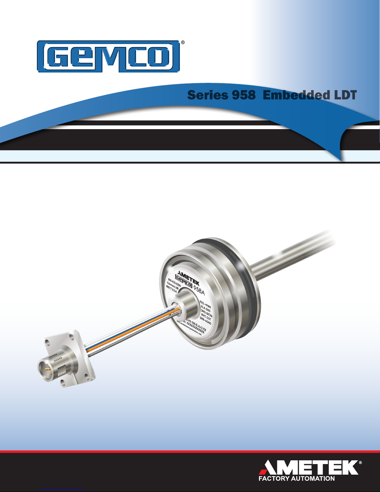
Series 958 Embedded LDT
Embedded Linear Displacement Transducer
Installation Manual
958A
ABSOLUTE PROCESS CONTROL
KNOW WHERE YOU ARE... REGARDLESS
Page 2

Contents
Chapter 1: 958A Overview ........................................................................................ 3
1.1 Dimension Drawing ............................................................................................. 4
Chapter 2: Installation ............................................................................................... 5
2.1 Installing in a Hydraulic Cylinder ...................................................................... 5
2.2 Magnet Installation ............................................................................................. 5
2.3 Mounting ............................................................................................................. 6
2.4 Set Screw Installation ........................................................................................ 6
Chapter 3: Connections & Wiring ............................................................................ 7
3.1 Wiring .................................................................................................................. 7
3.2 Pinouts and Wiring ............................................................................................. 8
3.3 Features – Automation Gain Control ................................................................ 9
3.4 Setting Zero & Span Positions .......................................................................... 9
Appendix A: Part Numbering ................................................................................. 10
Appendix B: Specications .....................................................................................11
NOTE: Ametek has checked the accuracy of this manual at the time it was
approved for printing. This manual may not provide all possible ways of
installing and maintaining the LDT. Any errors or additional possibilities to the
installation and maintenance of the LDT will be added in subsequent editions.
Comments for the improvement of this manual are welcome.
Ametek reserves the right to revise and redistribute the entire contents or
selected pages of this manual. All rights to the contents of this manual are
reserved by Ametek.
Unpacking
Carefully remove the contents of the shipping carton and check each item
on the packing slip before destroying the packing materials. Any damage
must be reported to the shipping company. If you do not receive all of the
parts, contact Ametek at 800-635-0289 (US and Canada) or 248-435-0700
(International).
Most probes are shipped in a Tube. To remove the metal end cap, use a large,
flat blade screw driver or a metal rod and tap on the inner edge of the cap until
it pivots. Grab the cap and pull it out. Use caution as the edge of the metal
cap may be sharp.
If you have an RMA warranty claim, pack the
probe in a shipping tube or with stiff reinforcement
to prevent the probe from being bent in transit.
Page 3
Installation Manual
Chapter 1: 958A Overview
We know today’s industrial challenges are extreme, so we designed and built a sensor to meet and exceed
these demands, regardless of the application or environment. Innovation, proprietary technology and decades of
experience were the key to the development of our 958A Embedded Linear Displacement Transducer.
The 958A was designed with the mobile hydraulics market in mind. The 958A is a rugged, accurate, programmable
zero & span, auto-tuning, non-contact linear displacement transducer in a compact embedded rod-style package.
The embedded package style allows the unit to be totally installed inside of a hydraulic cylinder, thus protecting the
transducers from outside conditions. The transducer utilizes our field-proven Magnetostrictive technology to give
absolute analog position, accurate to 0.04% of the programmable sensing distance. A variety of different analog
outputs are available to meet your needs.
The 958 has a variety of truly unique features. The first one is the wide power range of 8 to 30 VDC @ 1.6 watts.
The LDT also has auto-tuning capability, the ability to sense a magnet other than the standard ring magnet and
adjust its signal strength accordingly. Our units offer a variety of different analog outputs, all with optional field
programmable Zero & Span points. Units can be ordered in English or metric span lengths from 2" to 100" (50mm
to 2540mm), and come standard with either integral cable assemblies, bare leads or M12 style connectors.
The 958A units offers a unique diagnostic capability. When the magnet is present and within the programmed
range the unit will output a voltage or current within its selected range (depending on location of magnet). If the
magnet moves beyond the programmed ranges the output will indicate this with a voltage or current outside of the
selected range.
Voltage Output Specified at time of order (i.e. in Part Number)
Range 0 to +10VDC
Resolution 16 bits (0.0015% of span)
V0
Fault Condition Loss of Magnet 10.2V, below or above
Range +10 to 0VDC
Resolution 16 bits (0.0015% of span)
V1
Fault Condition Loss of Magnet 10.2V, below or above
Range 0 to +5VDC
Resolution 15 bits (0.0031% of span)
V2
Fault
Condition
Range +5 to 0VDC
Resolution 15 bits (0.0031% of span)
V3
Fault Condition Loss of Magnet 5.2V, below or above
Curent Output Specified at time of order (i.e. in Part Number)
Range 20 to 4mA
Resolution 15.7 bits, calibrated for 3.5-21mA (0 -
C2
Fault Condition Loss of Magnet 3.8mA, below or above
programmed range -0.1V or 10.1V
programmed range 10.1V or -0.1V
Loss of Magnet 5.2V, below or above
programmed range -0.1V or 5.1V
programmed range 5.1V or -0.1V
21mA, 16 bits )
programmed range 20.1mA or 3.9mA
Range 0.25 to +4.75VDC
Resolution ~15 bits (0.0034% of span) (14.85 bits)
V4
Fault Condition Loss of Magnet 5.2V, below or above
Range +4.75 to 0.25VDC
Resolution ~15 bits (0.0034% of span) (14.85 bits)
V5
Fault Condition Loss of Magnet 5.2V, below or above
Range 0.5 to +4.5VDC
Resolution ~15 bits (0.0034% of span) (14.68 bits)
V6
Fault Condition Loss of Magnet 5.2V, below or above
Range +4.5 to 0.5VDC
Resolution ~15 bits (0.0034% of span) (14.68 bits)
V7
Fault Condition Loss of Magnet 5.2V, below or above
programmed range -0.1V or 5.1V
programmed range 5.1V or -0.1V
programmed range -0.1V or 5.1V
programmed range 5.1V or -0.1V
Range 4 to 20mA
Resolution 15.7 bits, calibrated for 3.5-21mA
C4
Fault Condition Loss of Magnet 3.8mA, below or above
(0 - 21mA, 16 bits )
programmed range 3.9mA or 20.1mA
All units can easily be changed in the field for reverse operation. See section 3.4 Setting Zero & Span Positions.
Toll Free: 800-635-0289 • Email: [email protected] • Web: www.ametekfactoryautomation.com
3
Page 4
Series 958 Embedded Linear Displacement Transducer
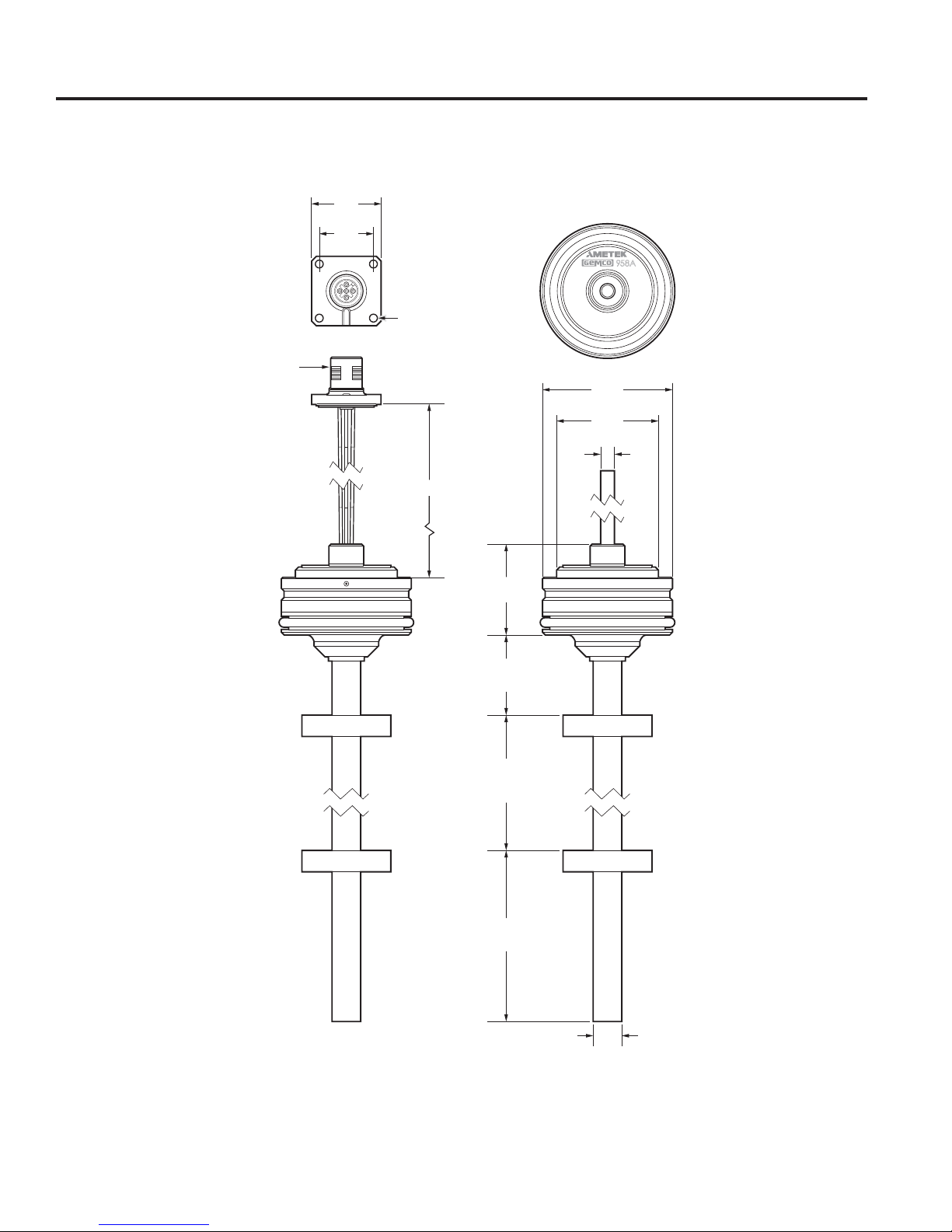
1.1: 958A Dimension Drawing
0.98
(25.0)
0.78
(19.8)
Ø .13
(3.2)
M12 (A CODE)
FIELD INSTALLABLE
RECEPTICLE
CONNECTOR
A
800-835-0290
Clemson, MI
U.S.A
.
48017
PART No: 958a-V0-100-E-A-C10X
SERIAL No: XXXXXXXXXXXX
www.ametekfactoryautomation.com
Ø 1.89
(48.0)
Ø 1.47
(37.3)
958A
RED-+PWR
BLK
ORG
WHT
-
GRN
Ø .21
(5.3)
-
GND
-
SETIN
-
OUT
AGND
1.31
(33.3)
NULL ZONE
1.18
(30.0)
STROKE LENGTH
2.0 (50.0)
to
100.0 (2540.0)
DEAD ZONE
2.49
(63.2)
Ø .41 (10.29)
Ø .31 (8.0)
or
Figure 1-1: 958A Dimension Drawing
(PD-0126000)
4
1080 North Crooks Road, Clawson, MI 48017 • Phone: 248-435-0700
Page 5
Installation Manual
Position Magnet
Non-ferrous spacer
30 mm (1.18 in.)
5 mm
(0.19 in.)
Piston
Chapter 2: Installing the LDT
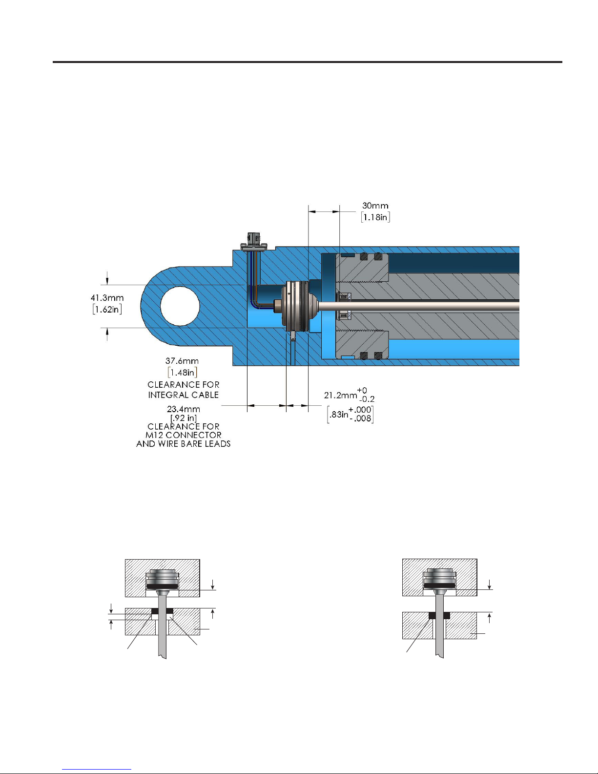
The 958A is designed for insertion into mobile hydraulic and clevis style cylinders. The hydraulic cylinder must be
prepped for an Embedded Style Linear Transducer.
Installation Notes: The 958A is offered in either a 10.29mm (.405") or an 8mm (.315) diameter guide tube. There
are 4 different magnet styles offered. When the magnet is installed in a ferrous material it is necessary to add a
non-ferrous spacer between the magnet and piston. Non-ferrous materials, such as brass, copper, aluminum,
non-magnetic stainless steel, or plastics, can be in direct contact with the magnet assembly and rod end without
producing any adverse results. See Figure 2-2.
Figure 2-1: 958A Embedded installed in hydraulic cylinder
Drawing is for reference only. For detailed cylinder machining, contact application support.
2.2: Magnet Mounting Detail
Ferrous Piston Non-Ferrous Piston
5 mm
(0.19 in.)
Position Magnet
Magnet installation in ferrous material Magnet installation in non-ferrous material
30 mm (1.18 in.)
Piston
Non-ferrous spacer
30 mm (1.18 in.)
Piston
Position Magnet
Figure 2-2: Magnet mounting detail
Toll Free: 800-635-0289 • Email: [email protected] • Web: www.ametekfactoryautomation.com
5
Page 6
Series 958 Embedded Linear Displacement Transducer
NULL ZONE
1.18 [30]
.41 [10.29]
OR
.31 [8]
1.89
[48]
f7
1.81
[46]
.21
[5.3]
21.2
-0
0.2
.83
+
-
.000
.007
1.31
[33.3]
1.47
[37.3]
.32
[8.1]
STROKE LENGTH
2.00 [50] TO
100.00 [2500]
DEAD ZONE
63.2
2.49
23.9
.94
A
+
.0
958A EMBEDDED LDT WITH CABLE (CONNECTOR OPTION C_)
NULL ZONE
1.18 [30]
.41 [10.29]
OR
.31 [8]
21.2
-0
0.2
.83
+
-
.000
.007
1.31
[33.3]
.32
[8.1]
STROKE LENGTH
2.00 [50] TO
100.00 [2500]
DEAD ZONE
63.2
2.49
23.9
.94
A
+
.0
958A EMBEDDED LDT WITH CABLE (CONNECTOR OPTION C_)
CABLE WIRING CHART (CONNECTOR
OPTION C_)
WIRE COLOR
DESCRIPTION
RED
POWER SUPPLY
BLACK
POWER SUPPLY
COMMON
ORANGE
PROGRAMMING
INPUT
WHITE
ANALOG OUTPUT
GREEN
ANALOG OUTPUT
RETURN
SHIELD TO GROUND (HOUSING)
BARE WIRES WIRING CHART
(CONNECTOR OPTION W_)
WIRE COLOR
DESCRIPTION
Connector Insert
engaged in
2
Connector view
Connector Insert
2
Connector view
NULL ZONE
1.18 [30]
.41 [10.29]
OR
.31 [8]
1.89
[48]
f7
1.81
[46]
.21
[5.3]
21.2
-0
0.2
.83
+
-
.000
.007
1.31
[33.3]
1.47
[37.3]
.32
[8.1]
STROKE LENGTH
2.00 [50] TO
100.00 [2500]
DEAD ZONE
63.2
2.49
23.9
.94
A
+
.0
.16 [4]
.18 [4.5]
45°
DETAIL A
SCALE 2 : 1
25
.98
19.80
.78
958A EMBEDDED LDT WITH CABLE (CONNECTOR OPTION C_)
CABLE WIRING CHART (CONNECTOR
WIRE COLOR
A
DETAIL B
SCALE 2 : 1
NOTES:
1. ALL DIMENSIONS IN INCHES [MM].
958A EMBEDDED LDT WITH FIELD INSTALLABLE M12 CONNECTOR
(CONNECTOR OPTION G_S1)
FIELD INSTALLABLE M12 CONNECTOR PIN
DESCRIPTION (CONNECTOR OPTION G_S1)
PIN
NUMBER
WIRE
COLOR
DESCRIPTION
1
BROWN
POWER SUPPLY
2
WHITE
PROGRAMMING
INPUT
3
BLUE
POWER SUPPLY
COMMON
4
BLACK
ANALOG OUTPUT
5
GRAY
ANALOG OUTPUT
RETURN
CONNECTOR
OPTION
DIMENSION "A"
G060S1
2.36 [60]
G250S1
9.84 [250]
GREEN
RETURN
SHIELD TO GROUND (HOUSING)
BARE WIRES WIRING CHART
(CONNECTOR OPTION W_)
WIRE COLOR
DESCRIPTION
RED
POWER SUPPLY
BLACK
POWER SUPPLY
COMMON
ORANGE
PROGRAMMING
INPUT
WHITE
ANALOG OUTPUT
GREEN
ANALOG OUTPUT
RETURN
FULL
C
B.D.B.
12/07/16
J.S.B.
12/09/16
DIM. DRAWING
PD-0126000
2
958A SERIES
EMBEDDED LDT
A
DETAIL B
SCALE 2 : 1
NOTES:
1. ALL DIMENSIONS IN INCHES [MM].
958A EMBEDDED LDT WITH FIELD INSTALLABLE M12 CONNECTOR
(CONNECTOR OPTION G_S1)
FIELD INSTALLABLE M12 CONNECTOR PIN
DESCRIPTION (CONNECTOR OPTION G_S1)
PIN
NUMBER
WIRE
COLOR
DESCRIPTION
1
BROWN
POWER SUPPLY
2
WHITE
PROGRAMMING
INPUT
3
BLUE
POWER SUPPLY
COMMON
4
BLACK
ANALOG OUTPUT
5
GRAY
ANALOG OUTPUT
RETURN
CONNECTOR
OPTION
DIMENSION "A"
G060S1
2.36 [60]
G250S1
9.84 [250]
GREEN
ANALOG OUTPUT
RETURN
SHIELD TO GROUND (HOUSING)
BARE WIRES WIRING CHART
(CONNECTOR OPTION W_)
WIRE COLOR
DESCRIPTION
RED
POWER SUPPLY
BLACK
POWER SUPPLY
COMMON
ORANGE
PROGRAMMING
INPUT
WHITE
ANALOG OUTPUT
GREEN
ANALOG OUTPUT
RETURN
FULL
C
B.D.B.
12/07/16
J.S.B.
12/09/16
DIM. DRAWING
PD-0126000
2
958A SERIES
EMBEDDED LDT
A
DETAIL B
SCALE 2 : 1
NOTES:
1. ALL DIMENSIONS IN INCHES [MM].
958A EMBEDDED LDT WITH FIELD INSTALLABLE M12 CONNECTOR
(CONNECTOR OPTION G_S1)
FIELD INSTALLABLE M12 CONNECTOR PIN
DESCRIPTION (CONNECTOR OPTION G_S1)
PIN
NUMBER
WIRE
COLOR
DESCRIPTION
1
BROWN
POWER SUPPLY
2
WHITE
PROGRAMMING
INPUT
3
BLUE
POWER SUPPLY
COMMON
4
BLACK
ANALOG OUTPUT
5
GRAY
ANALOG OUTPUT
RETURN
CONNECTOR
OPTION
DIMENSION "A"
G060S1
2.36 [60]
G250S1
9.84 [250]
SHIELD TO GROUND (HOUSING)
BARE WIRES WIRING CHART
(CONNECTOR OPTION W_)
WIRE COLOR
DESCRIPTION
RED
POWER SUPPLY
BLACK
POWER SUPPLY
COMMON
ORANGE
PROGRAMMING
INPUT
WHITE
ANALOG OUTPUT
GREEN
ANALOG OUTPUT
RETURN
FULL
C
B.D.B.
12/07/16
J.S.B.
12/09/16
DIM. DRAWING
PD-0126000
2
958A SERIES
EMBEDDED LDT
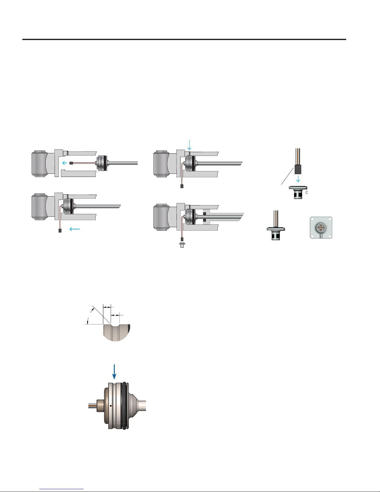
2.3: Mounting
There are 4 basis steps to install LDT into cylinder.
1. During assembly of the cylinder install LDT
2. Route cable or M12 connector through cylinder
3. Install Set screws to hold LDT in place (M5x10 max.), 3 set screws recommended at 120°. torque 0.05Nm
See Figure 2-4 Set Screw Channel Detail
4. Insert connector into M12 shell and secure to cylinder
1
4a. Exploded view step 4
3
2
Figure 2-3: Mounting
2.4: Set Screw Channel Detail
DETAIL A
SCALE 2 : 1
.16 [4]
.18 [4.5]
45°
6
4
1080 North Crooks Road, Clawson, MI 48017 • Phone: 248-435-0700
Sealing
O-ring
engaged in
Connector Shell
Fastening: Fasten the 958A Embedded LDT into the
cylinders 48mm bore, the O-ring and support ring
must be in place to seal the electronics form hydraulic
fluid. The housing of the transducer is fastened in
place with three M5x10max (or UNC / UNF equivalent)
set screws at 120° apart. Torque to 0.5Nm.
Figure 2-4: Set screw channel detail
Connector
Insert
Connector
Shell
Page 7

Installation Manual
Chapter 3: Connections and Wiring
Once the LDT has been installed, wiring connections can be made. Units are available with Integral cable
assemblies, bare leads or 5 pin M12 (A-Code) connector options. Refer to part numbering on unit in question for
proper wiring. See Appendix A for part numbering grid. See Figure 3-2 for connection options.
Once the LDT has been installed, wiring connections can be made. On units with the M12 connector option it is
recommended to uses an industry standard 5 pin 12mm Euro style cordset with a shield tied to the coupling nut.
On units with our Integral Cable option the shield is tied directly to the LDT’s housing. To reduce electrical noise
the shield must be properly used. Connect the cable’s shield to the controller system Ground. Always observe
proper grounding techniques and isolate high voltage (i.e. 120/240VAC) from low voltage (i.e. 24 VDC cables).
Warning: Do not use molded cordsets with LEDs!
It is preferable that the cable between the LDT and the interface device be one continuous run. If you are using a
junction box, it is recommended that the splice junction box be free of AC and/or DC transient-producing lines. The
shield should be carried through the splice and terminated at the interface device end.
NOTE: When grounding the LDT, a single earth ground should be connected to the Power Supply Common (circuit
ground). The LDT Power Supply Common should be connected to the Power Supply Common (-) terminal. The LDT
power supply (+VDC) should be connected to the power supply positive terminal (+). The LDT cable shield should
be tied to earth ground at the power supply. The LDT analog common should not be connected to earth ground
and should be used for connection to interface devices only.
The 958A offers up to 16-Bits of resolution, and is fully programmable over the entire active stroke length. Keep in
mind that there is a 1.18” Null Zone at the connector end of the LDT and a 2.49” Dead Band at the other end of the
LDT that the magnet must stay out of at all times. The units come fully programmed from the factory and do not
require re-programming unless desired.
The analog output is referenced to the analog common terminal and should not be referenced to any of the other
common terminals. For wiring, see Figure 3-1. For programming Zero and Span, See Section 3.4.
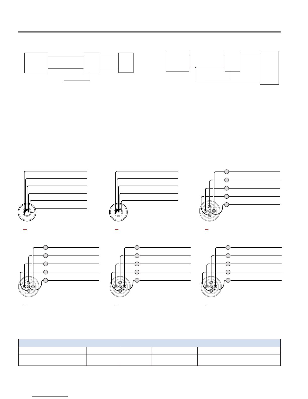
3.1: Wiring
Figure 3-1 shows two common methods for wiring the 958A to a customer supplied interface device, such as a PLC
or motion controller. The two different methods are commonly referred to as Single Ended Input and Differential
Input. Differential Input is the preferred wiring method.
With the Differential Input, the Analog Common wire is connected to the customer supplied input device and
the Power Supply Common is wired separately to the customers supplied power source. When wired using the
Differential method, the electrical noise and voltage offset errors produced by the currents running through the
Power Supply Common are eliminated. The Power Supply Common and Analog Common are internally connected
inside of the 958A LDT.
Toll Free: 800-635-0289 • Email: [email protected] • Web: www.ametekfactoryautomation.com
7
Page 8
Series 958 Embedded Linear Displacement Transducer
OUTPUT LOADING
Voltage: 2k Ω minimum
Current: 500 Ω maximum
CONNECTION OPTIONS
Integral Cable: Multi-conductor, 26 AWG, shielded, TPU jacket
5 Pin – M12: A-Code, Shell installed from "outside" cylinder
(IEC 61076-2-101)
Wire – Bare Leads: Multi-conductor, 26 AWG
APPROVALS
l CE (Electromagnetic Compatibility)—2014/30/EU
l RoHS 2—2011/65/EU
l Electromagnetic compatibility - Part 6-4: Generic
standards – Emission standards for industrial environ-
ments—EN61000-6-4
l Electromagnetic compatibility (EMC) - Part 6-2: Generic
standards – Immunity for industrial environments—
EN61000-6-2
l Agricultural and forestry machinery—ISO 14982:1998
l Road vehicles - electrical disturbances from nar-
rowband radiated electromagnetic energy — Part 5:
Stripline—ISO 11452-5
l Road vehicles - Electrical disturbances from conduction
and coupling—ISO 7637-1/2/3
l Earthmoving Machinery—ISO 13766
l Industrial Trucks—EN 12895
l Railway Applications—EN 50121-3-2
Pinouts and Wiring
(C_ ) Integral Cable
(W
_
) Wire – Bare Leads
* **
(G_S1) M12 – 5 Pin (A Code)
Analog Common (Green)
Analog Out (White)
Program (Orange)
Power Supply Common (Black)
VDC Power (Red)
Analog Common (Green)
Analog Out (White)
Program (Orange)
Power Supply Common (Black)
VDC Power (Red)
VDC Power (Brown)
1
2
Power Supply Common (Blue)
Program (White)
3
Analog Out (Black)
4
Analog Common (Gray)
5
958A LDT Linear Displacement Transducer
OUTPUT LOADING
Voltage: 2k Ω minimum
Current: 500 Ω maximum
CONNECTION OPTIONS
Integral Cable: Multi-conductor, 26 AWG, shielded, TPU jacket
5 Pin – M12: A-Code, Shell installed from "outside" cylinder
(IEC 61076-2-101)
Wire – Bare Leads: Multi-conductor, 26 AWG
APPROVALS
l CE (Electromagnetic Compatibility)—2014/30/EU
l RoHS 2—2011/65/EU
l Electromagnetic compatibility - Part 6-4: Generic
standards – Emission standards for industrial environ-
ments—EN61000-6-4
l Electromagnetic compatibility (EMC) - Part 6-2: Generic
standards – Immunity for industrial environments—
EN61000-6-2
958A LDT Linear Displacement Transducer
Power
Supply
8-30 VDC
958A
LDT
+ Input
- Input
Customer
Supplied Power
Power
Supply Common
Position
Output
Position
Common
Program Input
+
_
OUTPUT LOADING
Voltage: 2k Ω minimum
Current: 500 Ω maximum
CONNECTION OPTIONS
Integral Cable: Multi-conductor, 26 AWG, shielded, TPU jacket
5 Pin – M12: A-Code, Shell installed from "outside" cylinder
(IEC 61076-2-101)
Wire – Bare Leads: Multi-conductor, 26 AWG
APPROVALS
l CE (Electromagnetic Compatibility)—2014/30/EU
l RoHS 2—2011/65/EU
l Electromagnetic compatibility - Part 6-4: Generic
standards – Emission standards for industrial environ-
ments—EN61000-6-4
l Electromagnetic compatibility (EMC) - Part 6-2: Generic
standards – Immunity for industrial environments—
EN61000-6-2
Pinouts and Wiring
Analog Common (Green)
Analog Out (White)
Program (Orange)
Power Supply Common (Black)
VDC Power (Red)
VDC Power (Brown)
1
2
Power Supply Common (Blue)
Program (White)
3
Analog Out (Black)
4
Analog Common (Gray)
5
958A LDT Linear Displacement Transducer
Power
Supply
8-30 VDC
Customer
Supplied Power
+
Power
Supply Common
_
Program Input
Differential Input
958A
LDT
Position
Output
Position
Common
+ Input
- Input
Power
Supply
8-30 VDC
Customer
Supplied Power
+
Power
Supply Common
_
Program Input
Single Ended Input
958A
LDT
Position
Output
+ Input
Common
(Preferred Method)
Figure 3-1: Wiring – Single Ended vs. Differential
The 958A-C is current sourcing, which allows the current to flow from the LDT into the user’s equipment.
3.2: Pinouts and Wiring
There are six different connection options available. Refer to part numbers on unit in question for proper wiring.
VDC Power (Red)
VDC Power (Brown)
Power Supply Common (Blue)
Power Supply Common (Black)
Program (White)
Program (Orange)
Analog Out (Black)
Analog Out (White)
Analog Common (Gray)
Analog Common (Green)
No Connect (Pink)
Power Supply Common (Black)
(C) Integral Cable (W) Wire – Bare Leads (GS1) M12 – 5 Pin (A Code)
VDC Power (Red)
Program (Orange)
Analog Out (White)
Analog Common (Green)
1
2
Power Supply Common (Blue)
3
4
5
VDC Power (Brown)
Program (White)
Analog Out (Black)
Analog Common (Gray)
1
2
(MS1) M12 – 5 Pin (A Code) (MS2) M12 – 5 Pin (A Code) (MS3) M12 – 5 Pin (A Code)
indicates wire length. Refer to part numbers Appendix A for available options
Figure 3-2: Pinouts and Wiring
Multi-conductor Shielded 26 PUR -40° to 90°C Fixed Applications 1.05"
Power Supply Common (Blue)
3
4
5
Cable Type Gauge Jacket Temp Bend Radius
VDC Power (Brown)
Analog Out (White)
Analog Common (Black)
Program (Gray)
8
Cable Specifications
1080 North Crooks Road, Clawson, MI 48017 • Phone: 248-435-0700
Analog Common (Brown)
1
2
Power Supply Common (Blue)
3
4
5
VDC Power (White)
Analog Out (Black)
Program (Gray)
Moving Applications 3.15"
1
2
Power Supply Common (Blue)
3
4
5
VDC Power (Brown)
Analog Common (White)
Analog Out (Black)
Program (Gray)
Page 9

Installation Manual
!
3.3: Features
Automatic Gain Control
The Automatic Gain Control feature will automatically search and find the magnet on power up and adjust the
signal strength to the optimum setting. If power is applied without a magnet on the LDT, the LDT will go into a fault
condition and transmit a voltage or current outside of the programmed range. See Chapter 1: 958A Overview, for
list of fault conditions and outputs. To correct this, turn power off and place magnet within the active stroke area,
re-apply power.
3.4: Setting Zero & Span Positions
As an option the 958A can be ordered with Programmable Zero & Span positions. See page 10 part numbering to
see if this option filed was selected. Note: If option “P” was not selected in part number configuration, the unit is
non-programmable.
All units come fully programmed from the factory and do not require re-programming unless desired. The units
are 100% absolute and will not lose programmed parameters on power loss. The Zero and Span points can be
programmed in any order and anywhere within the LDT’s active sensor area.
NOTE 1: Zero or Span can be adjusted individually without setting the other.
NOTE 2: Zero = 0V on 0-10 VDC, 0V on 0-5 VDC, .25 on .25-4.75 VDC, .5 on .5-4.5 VDC units and 4mA on 4-20mA
units.
There is a timing sequence that is used to unlock the probe for programming. This is to insure that the Zero or Span
positions cannot be accidentally re-programmed by someone in the field.
Manual Setting of Zero & Span
To set the Zero and Span position, follow these steps:
1. Apply power to the LDT.
2. Place magnet assembly where Zero is to be located, but within the active region of the probe.
3. Short the Program Input pin to the Power Supply Common for 4 seconds. Remove the short for 1 second.
Within 5 seconds, short the Programming Input pin to the Power Supply Common. This completes the Zero
programming process.
4. Place magnet assembly where Span is to be located, but within the active region of the probe.
5. Short the Program Input pin to the Power Supply Common for 4 seconds. Remove the short for 1 second.
Within 5 seconds, short the Programming Input pin to the Power Supply +VDC.
This completes the programming process.
NOTE: The LDT must be unlocked to program the Zero and unlocked again to program the Span. Once either the
Zero or Span is programmed the LDT will go back into the locked mode.
Toll Free: 800-635-0289 • Email: [email protected] • Web: www.ametekfactoryautomation.com
WARNING: During normal operation, electrically insulate the Program wire to prevent accidental setting of
Span.
9
Page 10
Series 958 Embedded Linear Displacement Transducer
–
Insert length in meters .................................. . C
_
No options ............. X
Wire–Bare Leads–Insert length in millimeters ........................... W
_
Available lengths are 50, 100, 200, and 300 mm.
M12–5 Pin (A Code)–Field installable–Pin 1 Power (**) .................. G
_
S1
Available lengths are 60 and 250 mm.
M12–5 Pin (A Code)–Field installable–Pin assignment 1-2-3 (**) ........ . M
_
S1
Available lengths are 60 and 250 mm.
M12–5 Pin (A Code)–Field installable–Pin assignment 2-3-4 (**) ........ .M
_
S2
Available lengths are 60 and 250 mm.
M12–5 Pin (A Code)–Field installable–Pin assignment 1-3-4 (**) ........ .M
_
S3
Available lengths are 60 and 250 mm.
* Insert length of wire.
** Refer to the Wiring Diagrams on the previous page for Connector details.
Cable Assemblies
ANTI-VIBRATION DETENT
.59
(15.0)
M12 x 1
1.22
(31.0)
.98
(25.0)
.98
(25.0)
*
*
*
*
*
*
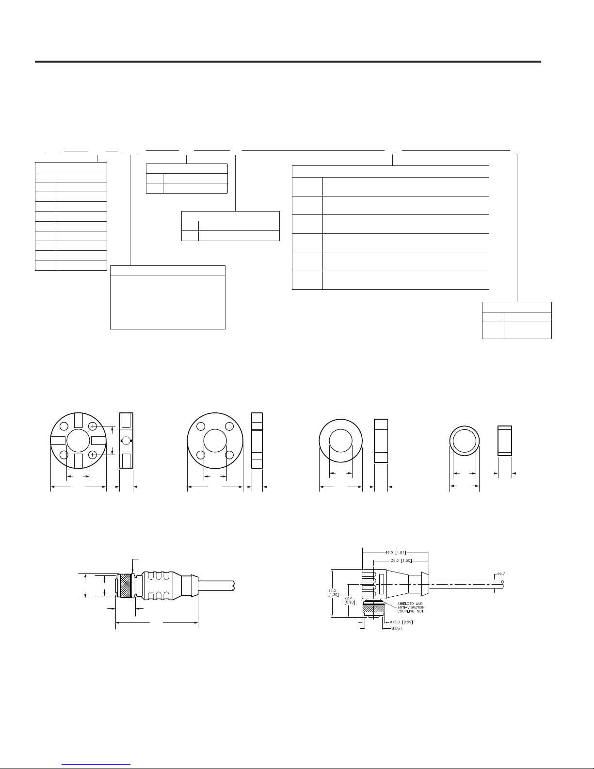
Appendix A: Part Numbering
The 958A Embedded LDT is available with a number of analog outputs and connector options. The numbering
scheme listed below will break down all available options. The “Unit of Measure” field will allow you to select either
inches or millimeters for the stroke length.
958A 0120V0 X
V0
V1
V2
V3
V4
V5
V6
V7
C2
C4
Output
0 to 10 VDC
10 to 0 VDC
0 to 5 VDC
5 to 0 VDC
.25 to 4.75 VDC
4.75 to .25 VDC
.5 to 4.5 VDC
4.5 to .5 VDC
20 to 4mA
4 to 20mA
Strokes in inches from 2" to 100"
in .1" increments
Stroke in millimeters from 50 to 2540mm
in 5mm increments
Entered as a 4 digit number
ie. 0120E is 12” stroke
ie 0100M is 100mm stroke
Unit of Measure
English (inches)
E
Metric (millimeters)
M
Stroke
Housing Type
48 mm Housing - 10 mm Rod
A
48 mm Housing - 8 mm Rod
B
Integral cable - Insert length in meters - Available lengths are
C_
2, 5 and 10 meters
Wire - Bare Leads - Insert length in millimeters - Available
W_
lengths are 50, 100, 200 and 300mm
M12 - 5 Pin (A-Code) - Field installable - Pin 1 Power (Insert
G_S1
length of wire) - Available lengths are 60 and 250mm
M12 - 5 Pin (A-Code) - Field installable - Pin assignment 1-2-3
M_S1
(Insert length of wire) - Available lengths are 60 and 250mm
M12 - 5 Pin (A-Code) - Field installable - Pin assignment 2-3-4 (Insert
M_S2
length of wire) - Available lengths are 60 and 250mm
M12 - 5 Pin (A-Code) - Field installable - Pin assignment 1-3-4
M_S3
(Insert length of wire) - Available lengths are 60 and 250mm
C5AE
Connector
Options
X
P
None
Programmable
& Zero Span
Accessories – Magnets and Cables
There are 4 magnet choices available for the 958 Series. Magnets and magnet spacers must be ordered as
separate line items.
Standard 4 Hole Magnet
P/N: SD0400800
Straight Connector
Cable M12-A Straight to flying leads – Shielded
2 meter: 949045L2M
5 meter: 949045L5M
10 meter: 949045L10M
.662
Ø .56
(14.2)
M12 x 1
TYP.
.31
ANTI-VIBRATION DETENT
.45
(11.5)
.53
1.29 .25
Non-Ferrous Spacer for
4 Hole Magnet
P/N: M0822400
1.91
(48.5)
.53
1.29
.53
.997/
.995
.312
1" Cylinder Magnet
P/N: SD0410300
17.4 mm Cylinder Magnet
.53 .312
.685
(17.4 mm)
P/N: 04588105
Right Angle Connector
Cable M12-A Right Angle to flying leads – Shielded
2 meter: 949046L2M
5 meter: 949046L5M
10 meter: 949046L10M
10
1080 North Crooks Road, Clawson, MI 48017 • Phone: 248-435-0700
Page 11
Installation Manual
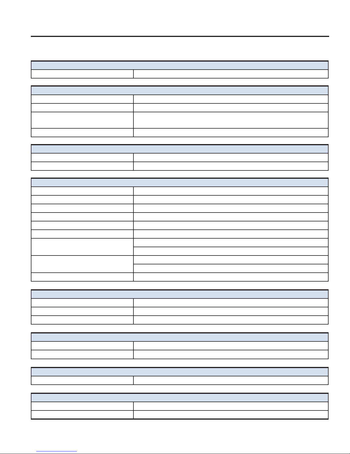
Appendix B: Specifications
General Specifications
Displacement 2" to 100" (50mm to 2540mm) in .1" or 5mm increments
Performance Specifications - Measurement
Linearity +/-0.04% of Span or +/-0.008", whichever is greater
Hysteresis 0.001" maximum
Repeatability Equal to Resolution of output signal, +/-0.01% of Span or 0.001", whichever is
greater
Update Time 0.5 ms minimum, proportional to length of LDT - not to exceed 4ms
Null & Dead Bands
Null 1.18" (30mm) from flat face of LDT housing
Dead 2.49" (63.25mm) from end of rod
Mechanical Specifications - Housing
Material - Housing Stainless Steel 1.4305 / AISI 303
Diameter 1.89" (48mm)
Length (width) 1.31" (33.3mm)
Guide Tube Material Stainless Steel 1.4404 / AISI 316/316L
Diameter - Guide Tube 8mm & 10mm (10.29mm actual)
Guide Tube Pressure
Continuous 10mm - 5,076 PSI (350 bar)
8mm - 4,351 PSI (300 bar)
Spike 10mm - 10,000 PSI (689 bar)
8mm - 5,801 PSI (400 bar)
Housing (O-ring) 5,076 PSI (350 bar)
Temperature
Head - Electronics -40°C to + 85°C
Guide Tube -40°C to + 105°C
Storage -40°C to + 105°C
Shock & Vibration
Shock 1,000 G’s, single hit (per IEC 60068-2-27)
Vibration 30 G’s, 10Hz - 2kHz (per IEC 60068-2-6)
Ingress Protection
Protection level IP68 (per EN 60529)
Electrical Specifications
Power Consumption 1.6 Watt maximum (50mA @ 24VDC typical)
Input Voltage 8 to 30VDC
Toll Free: 800-635-0289 • Email: [email protected] • Web: www.ametekfactoryautomation.com
11
Page 12
Series 958 Embedded Linear Displacement Transducer
Protection
Polarity Reverse polarity protected
Overvoltage Transient overvoltage protection to +33VDC
Output Resolution
0 to 10VDC 16 bits (0.0015% of span)
0 to 5VDC 15 bits (0.0031% of span)
0.25 to +4.75VDC ~15 bits (0.0034% of span)
0.5 to +4.5VDC ~15 bits (0.0034% of span)
4 to 20mA 15.7 bits, calibrated for 3.5-21mA (0 - 21mA, 16 bits)
Output Loading
Voltage 2kΩ minimum
Current 500Ω maximum
Connection Options
Integral Cable Multi-conductor, 26 AWG, shielded, PUR jacket (-40º C to +90º C)
5 Pin - M12 A-Code, Shell installed from “outside” cylinder (IEC 61076-2-101)
Wire - Bare Leads Multi-conductor, 26 AWG
Isolation
Housing to any signal 500V
Approvals
CE (Electromagnetic Compatibility) 2014/30/EU - When installed in grounded metal housing
RoHS 2 2011/65/EU
Electromagnetic compatibility - Part 6-4:
Generic standards –
Emission standards for industrial
environments
Electromagnetic compatibility (EMC) Part 6-2: Generic standards –
Immunity for industrial environments
Agricultural and forestry machinery ISO 14982:1998
Road vehicles - electrical disturbances
from narrowband radiated
electromagnetic energy — Part 5:
Stripline
Road vehicles - Electrical disturbances
from conduction and coupling
Earthmoving Machinery ISO 13766
Industrial Trucks EN 12895
Railway Applications EN 50121-3-2
EN61000-6-4
EN61000-6-2
ISO 11452-5
ISO 7637-1/2/3
12
1080 North Crooks Road, Clawson, MI 48017 • Phone: 248-435-0700
Page 13
953 VMAX LDT
955 BRIK
• Shock resistant to 1000Gs
• Vibration resistant to 30Gs
• Analog outputs, 0-10 VDC, +/-10
VDC, 0-5 VDC, +/-5 VDC, 4-20mA
• Digital output Start/Stop, Control
Pulse, and Variable Pulse (PWM)
• SSI (Synchronous Serial Interface)
24, 25, or 26 Bit, Binary or Gray
Code, Synchronous or Asynchronous Mode
• Removable cartridge
• IP68 rating
• Stroke length to 300"
• Input power range is 7 to 30 VDC
• Programmable zero and span
• Diagnostic Tri-Color LED
• Low profile LDT
• Analog output 4-20mA, 0-10 VDC,
+/-10 VDC, digital and quadrature outputs
• Programmable zero and span
• Stroke length to 180"
• Wide input voltage range
• Optional floating magnet
• Diagnostic LED
Copyright 2017 by AMETEK FACTORY AUTOMATION. All Rights Reserved. Made in the USA.
Other Products
MADE IN AMERICA
1080 North Crooks Road, Clawson, MI 48017
Phone: 248-435-0700 Toll Free: 800-635-0289
Email: [email protected]
Web: www.ametekfactoryautomation.com
958A.M3R
11/17.Z431
 Loading...