

Gemco 953A VMAX Instruction Manual

I
r
NSTALLATION
L
INEAR
D
ISPLACEMENT
M
T
RANSDUCERS
ANUAL
953A VMAX
™
Series 953
Series 956
Linear Displacement Transducer
lacement Transduce
ABSOLUTE PROCESS CONTROL
KNOW WHERE YOU ARE... REGARDLESS

Contents
Chapter 1: 953A Overview
Chapter 1: 953A Overview ....................................2
Chapter 2: Installing ..............................................4
2.1 Installing to a Mounting Bracket ........................4
2.2 Installing in a Hydraulic Cylinder .......................5
Chapter 3: Wiring ..................................................8
3.1 V0/V1 (Voltage) .................................................8
3.2 C4/C2 (Current) .................................................8
3.3 Setting Zero & Span Position ..........................12
Appendix A: Troubleshooting ............................13
Appendix B: Part Numbering .............................14
Appendix C: Specifi cations ................................ 15
NOTE: Ametek has checked the accuracy of this
manual at the time it was approved for printing. This
manual may not provide all possible ways of installing
and maintaining the LDT. Any errors or additional
possibilities to the installation and maintenance of the
LDT will be added in subsequent editions. Comments
for the improvement of this manual are welcome.
Ametek reserves the right to revise and redistribute
the entire contents or selected pages of this manual.
All rights to the contents of this manual are reserved
by Ametek. VMAX is a registered trademark of Gemco.
Unpacking
Carefully remove the contents of the shipping carton
and check each item on the packing slip before
destroying the packing materials. Any damage must be
reported to the shipping company. If you do not receive
all of the parts, contact Ametek at 800-635-0289 (US
and Canada) or 248-435-0700 (International).
Most probes are shipped
in a Tube. To remove the
metal end cap, use a large,
fl at blade screw driver or
a metal rod and tap on the
inner edge of the cap until
it pivots. Grab the cap and
pull it out. Use caution as
the edge of the metal cap may be sharp.
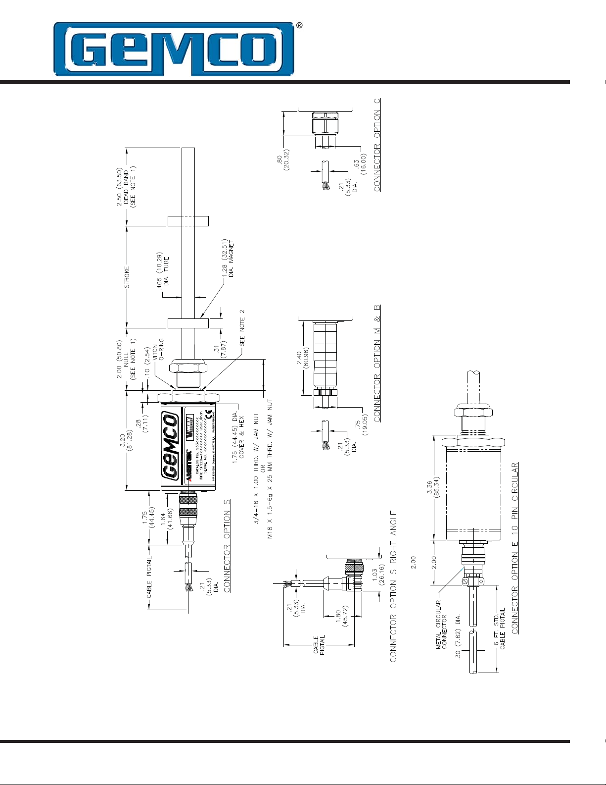
The 953A VMAX is a magnetostrictive Linear
Displacement Transducer (LDT) for highly accurate
continuous machine positioning in a variety of
industrial applications.
This sensor is built to withstand the most severe
environmental conditions and is completely absolute.
This means that power loss will not cause the unit to
lose position information or require re-zeroing. The
non-contact design allows this device to be used in
highly repetitive applications without mechanical wear.
The 953A VMAX has a few truly unique features. One
feature is the LDT’s auto-tuning capability, the ability to
sense a magnet other than the standard magnet and
adjust its signal strength accordingly. Another feature
is that the analog output is programmable over the
entire active stroke length. The active stroke area lies
between the Null Zone and Dead Band.
There is a diagnostic LED located at the connector
end of the probe that remains green while a good
magnet signal is present and when the magnet is in
the programmed stroke area. The LED turns yellow
when the magnet is out of the programmed active
range, but still within the active stroke area. The LED
turns RED if there is a loss of magnet and the output
will go to 0 volts on a voltage unit and 3.8mA on
current model units.
The 953A VMax LDT with a 4 to 20mA output offers a
unique diagnostic capability. The normal 4 to 20mA
output indicates the position of the magnet within the
programmed span. If the position of the magnet is
outside the set span, the output is either 3.9mA or
20.1mA. If the magnet moves into the Null or Dead
Zones or there is a loss of magnet the output will be
3.8mA. This feature is only available on units with a
current output. On voltage units the voltage output
will be 0 volts below the programmed zero point and
10volts above the programmed Span.
All units can easily be changed in the fi eld from a
0-10VDC to a 10-0VDC or a 4-20mA to a 20-4mA.
NOTE: The part number on the LDT is a record of the
characteristics that make up your specifi c unit. For a
translation of the part number, see Appendix B.
If you have an RMA warranty claim, pack the probe in
a shipping tube or with stiff reinforcement to prevent
the probe from being bent in transit.
TM
AUTOMATION & PROCESS TECHNOLOGIES
Figure 1-1 953A Dimension Drawing

Chapter 2: Installing the LDT
If a mounting bracket or other part is used that is
made of ferromagnetic material (a material readily
magnetized), it should be placed no closer than 0.25"
from the LDT's rod end to minimize the effects of
magnetic fl ux distortion. This can cause an in ac cu rate
measurement of the magnet position.
Non-ferrous materials, such as brass, copper,
aluminum, non-magnetic stain less steel, or plastics,
can be in direct contact with the magnet assembly and
rod end without producing any adverse results.
2.1: Installing the LDT to a
Mounting Bracket
Parts discussed in this section can be found in Figures
1-1 and 2-1.
1. Unscrew the LDT’s jam nut from the threads
protruding from the hex mounting base.
2. Insert the LDT’s rod end into the mounting
bracket’s hole. The mounting bracket may contain
a 3/4-16 UNF-2B threaded hole. In this case,
screw the LDT into this hole using the threads
protruding from the hex mounting base.
3. Once the LDT is in place, screw the jam nut
back onto the threads of the hex mounting base.
Use the 1.75" hex mounting base on the head
assembly to tighten the LDT to the bracket.
WARNING: Do not use the blue
aluminum cover of the head assembly
to tighten the LDT within the bracket
!
(see Figure 2-1). This may damage
the LDT and will void your warranty. To tighten
the LDT within the bracket, use the 1.75" hex
mounting base on the head assembly.
If the length of the LDT’s rod end is less than 30”, skip
to the sub-section: Mounting the Magnet Assembly.
with LDTs having a rod 30”-71” in length. Supporting
the end of the rod will minimize operational errors and
protect against damage due to shock and vibration.
If the length of the LDT’s rod is 72” or longer, it is
recommended that additional support brackets be
used . These additional support brackets must be made
of a non-ferrous material. Because these additional
support brackets will interfere with the magnet’s
movement, a special split-type magnet assembly must
be used. To order a split magnet (P/N SD0411200)
and support brackets (P/N SD0411100), contact the
factory at 800.635.0289.
To install a support bracket for an LDT having a rod
30”-71” in length, perform step 4a. If the rod is longer
than 71”, perform step 4b.
4a. If the support bracket is made of a ferromagnetic
material (material readily magnetized), install the
support bracket no closer than 0.25” from where
the LDT’s dead band ends and the area of stroke
begins. Continue to the sub-section: Mounting
the Magnet Assembly.
To install two or more support brackets for a LDT
having a rod 72" or longer in length, perform the
following steps:
4b. Install support brackets at increments of 48”
throughout the LDT’s rod . Support brackets
placed within the Null Zone and area of stroke or
closer than 0.25” to the beginning of these areas
must be made of a non-ferrous material.
Mounting the Magnet Assembly
Before mounting the magnet assembly , the following
should be considered:
• Ferromagnetic material should not be placed
closer than 0.25” from the LDT’s magnet assembly
or rod end. Failure to do so could cause erratic
operations.
Installing Support Brackets
It is recommended that a support bracket be used
• Minimal clearance between the LDT’s rod and
the magnet assembly through the full stroke is
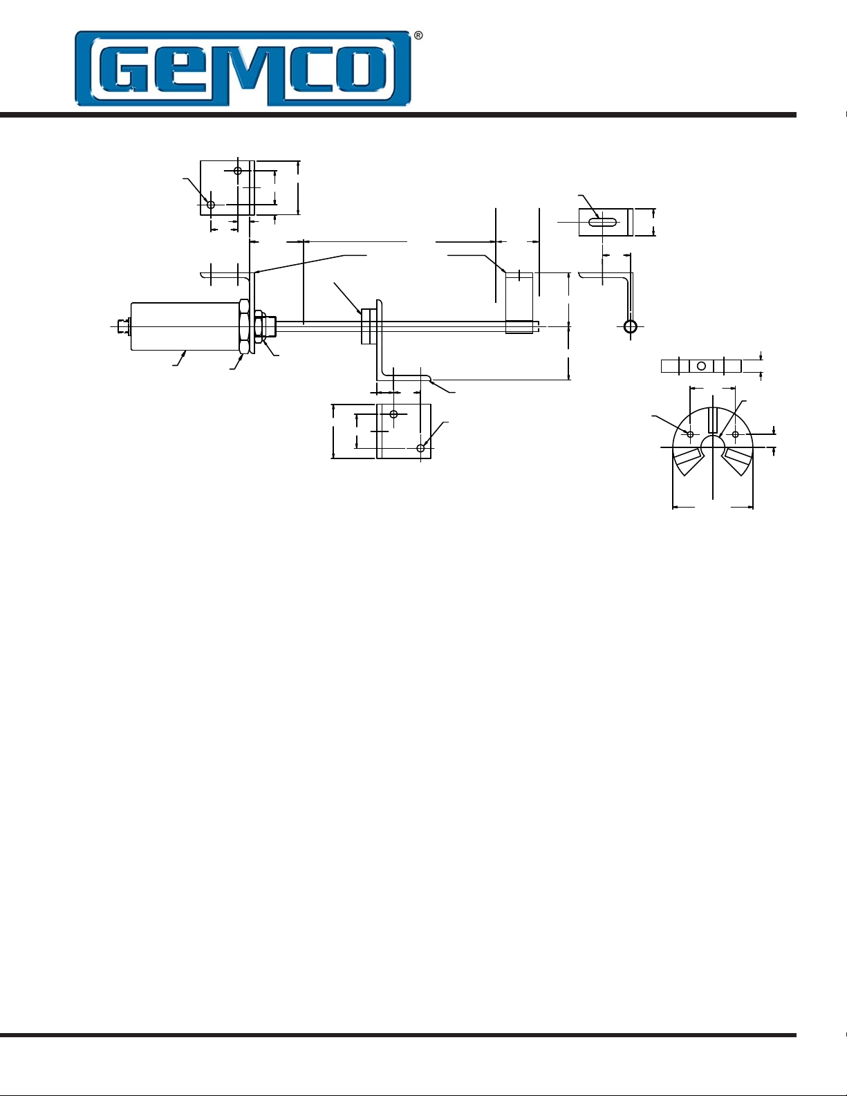
2 PLACES
.28
.44
1.00
1.25
.37
NULL
2.00
PROBE MOUNTING KIT
OPTIONAL
MAGNET
STROKE DEAD
(P/N 949003)
.28 X 1.03 SLOT
BAND
2.00
C
L
1.00
1.03
3/4-16 JAM NUT
PROBE
NOTES: UNLESS OTHERWISE SPECIFIED
1. MOUNTING KITS FURNISHED WITH
MOUNTING BOLTS.
2. MOUNTING BRACKETS ARE MADE FROM
3/16" X 2" X3" STAINLESS STEEL.
1.75 HEX
SUPPLIED W/PROBE
2.00
1.25
.62
1.00
Figure 2-1: Mounting the LDT
required. Stress between the magnet and the rod
can cause fl exing of the mounting brackets. This
may result in non-linearity.
• LDTs using a split magnet assembly must keep
the diameter of the magnet as sem bly around the
rod throughout the complete stroke. The diameter
of this magnet as sem bly should not be more than
0.2” away from the rod. Split magnet assemblies
outside of this range will cause signal loss.
To install the magnet assembly , perform the following
steps:
1. Slide the magnet assembly over the LDT rod .
2. Mount the magnet to the non-ferrous, movable
portion of the device being controlled using nonferrous screws.
MAGNET MOUNTING
KIT (P/N 949005)
.28
2 PLACES
2.00
.187 THRU
(2 PLACES)
NOTE: USE THIS MAGNET WITH ROD
S
1.407
S
N
NN
2.50 REF.
SUPPORT BRACKET SD0411100
.38
.75 THRU
SS
.406
2.2: Installing the LDT in a
Hydraulic Cylinder
Before installing an LDT in a hydraulic cylinder, note
the following considerations. Items discussed in this
section are found in Figures 1-1 and 2-1.
• A non-ferrous spacer must be used to separate the
magnet assembly from the head of the piston rod .
See Figure 2-2.
• The magnet should not be closer than 2.0” from the
base of the LDT’s hex head when the piston rod is
fully retracted. In instances where space restraints
exist, it may be required to countersink the magnet
into the piston rod. Two magnets are available
for mounting to the piston: the standard 1.29"
in diameter (P/N SD0400800) four-hole magnet
and the 1.0" magnet (P/N SD0410300) designed
exclusively for countersunk mounting applications.
The 1.0" magnet must be secured with a snap ring.

• An O-ring is provided at the base of the LDT’s
mounting hex for pres sure sealing. The O-ring seal
was designed to meet Mil-Std-MS33656. Refer to
SAE J514 or SAE J1926/1 for machining of mating
surfaces.
• A cham fered rod bushing in front of the magnet
may be required. It is recommended that a
chamfered rod bushing be used with LDTs having
a rod 60.0” or longer. This bushing will prevent
wear on the magnet assembly (wear occurs as the
piston retracts from extended lengths). This rod
bushing should be manufactured from a high wear
polymer, such as Tefl on®.
• It is recommended the bore for the cylinder
piston rod have an inside diameter of at least
0.50”. The LDT rod has an outside diameter of
0.405”. Use stan dard prac tic es for machining and
mounting these components. Consult the cylinder
man u fac tur er for details on applicable SAE or
military specifi cations.
It may be necessary to perform machining and
mounting operations on the hydraulic cylinder before
installing the LDT. Consult the information and
specifi cations provided by the cylinder manufacturer
before beginning the following steps:
1. Unscrew the LDT’s jam nut from the threads
protruding from the hex mounting base.
2. Position the non-ferrous spacer against the
piston face, followed by the magnet, and then the
chamfered rod bushing if the LDT’s rod is 60.0” or
longer in length.
If the leading edge of the magnet will come closer
than 2.0” from the base of the LDT’s hex head
when the piston rod is fully retracted, it will be
necessary to counterbore the magnet assembly
into the piston rod. Both the standard 1.29” fourhole magnet assembly (P/N SD0400800) and
the 1.0” magnet assembly (P/N SD0410300) are
designed for counterbored mounting applications.
If it has a 1.0” magnet assembly, a snap ring will
be needed to hold it in place.
4. Insert the LDT’s rod into the hole of the hydraulic
cylinder’s mounting bracket.
The protective Plug may need to be removed from
the hydraulic cylinder before inserting the LDT. The
end cap should contain a 3/4-16 UNF-2B threaded
hole. Screw the LDT into this hole using the
threads protruding from the LDT’s hex mounting
base.
WARNING: Do not use the blue
aluminum cover of the head assembly
!
to tighten the LDT within the bracket
(see Figure 2-1). This may damage
the LDT and will void your warranty. To tighten
the LDT within the bracket, use the 1.75" hex
mounting base on the head assembly.
With the LDT properly installed inside the hydraulic
cylinder, it may be necessary to assemble parts of the
hydraulic cylinder. For assistance in this task, refer to
the information provided by the cylinder manufacturer.
3. Insert non-ferrous screws through the chamfered
rod bushing (if used), magnet, and non-ferrous
spacer. Secure items by tightening screws.
6
AUTOMATION & PROCESS TECHNOLOGIES
®
1080 N. Crooks Road • Clawson, MI 48017 • 800.635.0289 • Phone 248.435.0700 • Fax 248.435.8120 • www.ametekapt.com
 Loading...