


INSTALLATION MANUAL
L
INEAR
D
ISPLACEMENT
T
RANSDUCERS
952 BlueOx
Linear Displacement Transducer
Series 952
Series 956
ABSOLUTE PROCESS CONTROL
KNOW WHERE YOU ARE... REGARDLESS

Contents
Chapter 1: Overview
Chapter 1: Overview .................................................................2
1.1 Dimension Drawing for all 952 LDTs ..................................3
Chapter 2: Installing the LDT ....................................................4
2.1 Installing the LDT to a Mounting Bracket ............................4
2.2 Installing the LDT in a Hydraulic Cylinder ...........................5
Chapter 3: 952 Wiring (A, CP, RS, VP, VPI) .............................8
3.1 952 Analog - V0, V1, V4 or V5 (Voltage) ............................9
3.2 952 Analog - C4 or C2 (Current)........... .................. ...........9
3.3 952 Analog - D0 or D1 (Differential Analog Output) ............9
3.4 952 Analog Wiring ............................................................10
3.5 952A (Analog) ..................................................................11
3.6 952 CP (Control Pulse) .....................................................11
3.7 952 VP (Variable Pulse) ...................................................12
3.8 952 RS (Start/Stop) ..........................................................13
3.9 952 CP, RS, VP Wiring .....................................................14
3.10 Setting Zero & Span Position (Analog Only) ..................15
3.11 Differential Analog Output (Options D0, D1, or D2) ........15
Chapter 4: 952 QD Overview .................................................16
4.1 Quadrature Output............................................................16
4.2 Signal Connection Application Note .................................16
4.3 Quadrature Output Resolution and Speed .......................18
4.4 952 QD Wiring Connection ...............................................18
4.5 Features ...........................................................................19
4.6 952 QD Wiring Diagram ...................................................20
4.7 952 QD Frequency ...........................................................23
Appendix A: Troubleshooting ..................................................24
A.1 Troubleshooting for 952 Analog LDTs ..............................24
A.2 Troubleshooting for 952 Analog LDTs ..............................26
A.3 Troubleshooting for 952 CP, RS, or VP LDTs ..................27
Appendix B: Ordering Information ..........................................29
B.1 Analog Part Numbering ....................................................29
B.2 Digital Part Numbering .....................................................30
B.3 Quadrature Part Numbering .............................................31
Appendix C: Specications .....................................................32
Glossary .................................................................................34
NOTE: AMETEK has checked the accuracy of this manual at
the time it was approved for printing. However, this manual may
not provide all possible ways of installing and maintaining the
LDT. Any errors found in this manual or additional possibilities
to the installation and maintenance of the LDT will be added
in subsequent editions. Any comments you may have for the
improvement of this manual are welcomed.
The GEMCO Model 952 BlueOx is a
Magnetostrictive Linear Displacement Transducer
(LDT). Each LDT offers highly accurate position
sensing. The BlueOx LDT is built to withstand the
most severe environmental conditions. The 952
digital and analog LDTs are completely absolute.
Power loss will not cause the unit to lose position
information or require re-zeroing. Also, the noncontact design allows this device to be used in
highly repetitive applications without mechanical
wear.
NOTE:
The series number on the LDT is a record of
all the specic characteristics that make up the unit.
This includes what interface type it is; its wire speed
(for digital LDTs); its output signal and range; the
type of connector the unit uses; and stroke, null and
dead band lengths. For a translation of the model
number, see Appendix B: Ordering Information.
The GEMCO 952 QD BlueOx is a magnetostrictive
Linear Displacement Transducer (LDT) for
continuous machine positioning in a variety of
industrial applications. The quadrature output
makes it possible to have a direct interface to
virtually any incremental encoder input or counter
card, eliminating costly absolute encoder converters
and special PLC interface modules.
The 952 QD BlueOx quadrature LDT can be
ordered with 1 to 9999 cycles per inch of output
resolution. The transducer features an input to re-
zero the probe on the y. Another unique feature is
the Burst mode; an input on the transducer triggers
a data transfer of all the incremental position data
relative to the transducer’s absolute zero position.
This is how incremental can provide absolute
functionality. The Burst input can be used to achieve
absolute position updates when power is restored
to the system or anytime an update is needed to rezero or home the machine.
AMETEK reserves the right to revise and redistribute the entire
contents or selected pages of this manual. All rights to the
contents of this manual are reserved by AMETEK. BlueOx is a
registered trademark of GEMCO.
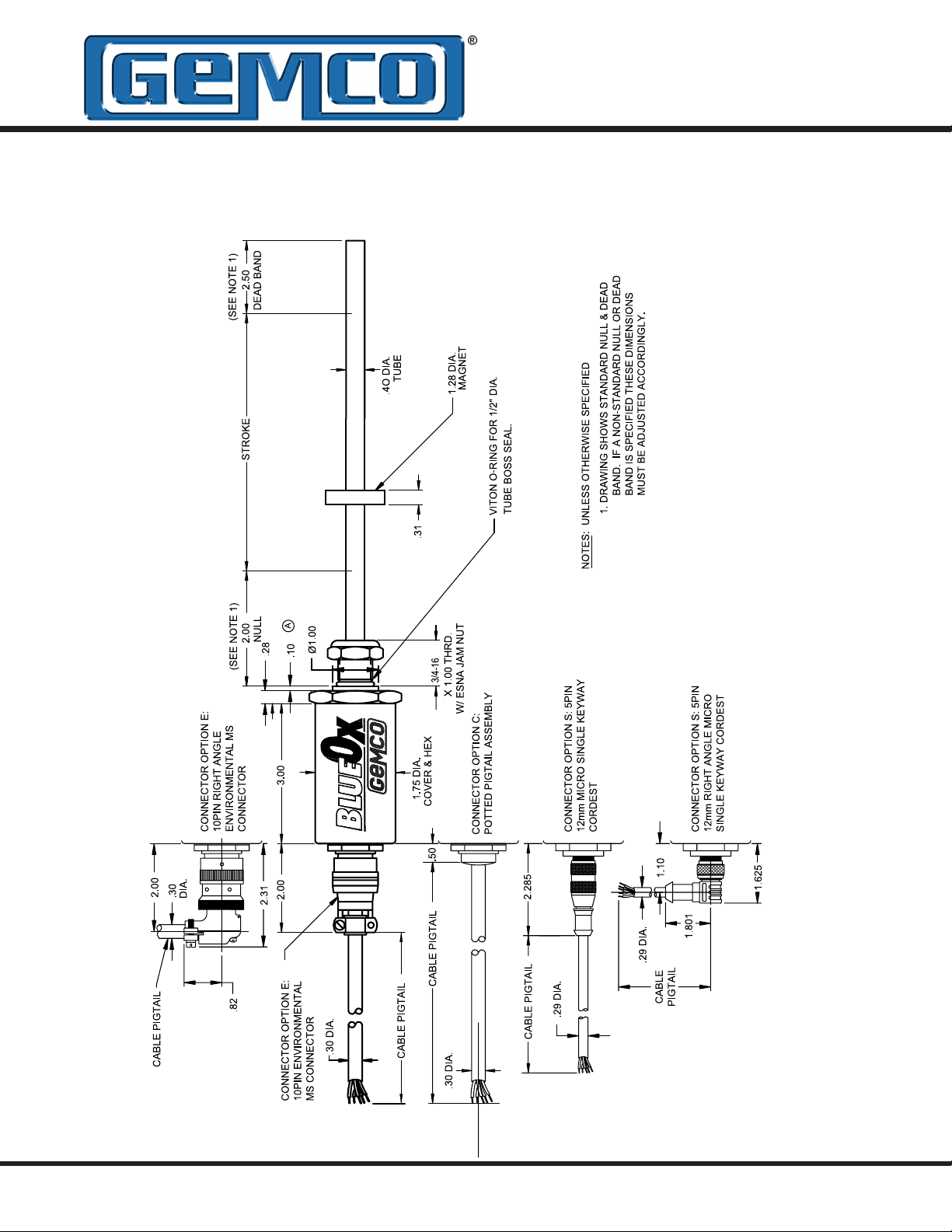
1.1: Dimension Drawing for all 952 LDTs
Drawing D0234200
Figure 1-1: BlueOx Linear Displacement Transducer

Chapter 2: Installing the LDT
Before installing the LDT, the following should be
considered:
• If a mounting bracket is used that is made of
ferromagnetic material (a material readily
magnetized), it should be placed no closer than
0.25" from the LDT's rod end.
• To minimize the effects of magnetic ux distortion
(which could cause an inaccurate measurement
of the magnet’s position), ferromagnetic material
should not be placed closer than 0.25” from the
magnet.
2.1: Installing the LDT to a
Mounting Bracket
Perform the following steps to install the LDT to a
mounting bracket.
are found in Figure 1-1. If the LDT is being installed
into a hydraulic cylinder, refer to Section 2.2:
Installing the LDT in a Hydraulic Cylinder.
1. Unscrew the LDT’s jam nut from the threads
protruding from the hex mounting base.
2. Insert the LDT’s rod end into the mounting
bracket’s hole. The mounting bracket may
contain a 3/4 − 16 UNF − 2B threaded hole. In
this case, screw the LDT into this hole using the
threads protruding from the hex mounting base.
3. Once the LDT is in place, screw the jam nut
back onto the threads of the hex mounting base.
Use the 1.75" hex mounting base on the head
assembly to tighten the LDT to the bracket.
WARNING: Do not use the blue aluminum cover
of the head assembly or connector/cable nut
(either a 1 1/16" Amphenol connector or 1 3/16"
cable nut) to tighten the LDT within the bracket
(see Figure 2-1). This may damage the LDT
and will void your warranty. To tighten the LDT
within the bracket, use the 1.75" hex mounting
base on the head assembly.
Parts discussed in this section
If the length of the LDT’s rod end is less than 30”,
skip to the sub-section: Mounting the Magnet
Assembly.
Installing Support Brackets
It is recommended that a support bracket be used
with LDTs having a rod 30”-71” in length. Supporting
the end of the rod will minimize operational errors
and protect against damage due to shock and
vibration. If the length of the LDT’s rod is 72” or
longer, it is recommended that additional support
brackets be used. These additional support brackets
must be made of a non-ferrous material. Because
these additional support brackets will interfere with
the magnet’s movement, a special split-type magnet
assembly must be used. To order a split magnet
(part number SD0411200) and support brackets
(part number SD0411100), contact Factory.
To install a support bracket for a LDT having a
rod 30”-71” in length, perform step 4a. If the rod is
longer than 71”, perform step 4b.
4a. If the support bracket is made of a
ferromagnetic material (material readily
magnetized), install the support bracket no
closer than 0.25” from where the LDT’s dead
band ends and the area of stroke begins.
Continue to the sub-section: Mounting the
Magnet Assembly.
To install two or more support brackets for a LDT
having a rod 72" or longer in length, perform the
following steps:
4b. Install support brackets at increments of 48”
throughout the LDT’s rod. Support brackets
placed within the null zone and area of stroke
or closer than 0.25” to the beginning of these
areas must be made of a non-ferrous material.

Mounting the Magnet Assembly
Before mounting the magnet assembly, the following
should be considered:
• Ferromagnetic material should not be placed
closer than 0.25” from the LDT’s magnet
assembly or rod end. Failure to do so could
cause erratic operations. Non-ferrous materials,
such as brass, copper, aluminum, non-magnetic
stainless steel, or plastics, can be in direct
contact with the magnet assembly and rod end
without producing any adverse results.
• Minimal clearance between the LDT’s rod and
the magnet assembly through the full stroke is
required. Stress between the magnet and the
rod can cause exing of the mounting brackets.
This may appear as nonlinearity.
• LDTs using a split magnet assembly must keep
the diameter of the magnet assembly around
the rod throughout the complete stroke. The
diameter of this magnet assembly should not be
farther than 0.2” away from the rod. Split magnet
assemblies outside this range will cause signal
loss.
To install the magnet assembly, perform the
following steps:
1. Slide the magnet assembly over the LDT rod.
2. Mount the magnet to the non-ferrous, movable
portion of the device being controlled using nonferrous screws.
2.2: Installing the LDT in a
Hydraulic Cylinder
Before installing an LDT in a hydraulic cylinder, note
the following considerations. Items discussed in this
section are found in Figures 1-1 and 2-1.
• A non-ferrous spacer must be used to separate
the magnet assembly from the head of the
piston rod. See Figure 2-1.
• The magnet should not be closer than 2.0”
from the base of the LDT’s hex head when the
piston rod is fully retracted. In instances where
space restraints exist, it may be required to
countersink the magnet into the piston rod.
Two magnets are available for mounting to
the piston: the standard 1.29" in diameter
(part number SD0400800) four-hole magnet
and a 1.0" magnet (part number SD0410300)
designed exclusively for countersunk mounting
applications. The 1.0" magnet must be held
captive with a snap ring.
• An O-ring groove is provided at the base of the
LDT’s mounting hex for pressure sealing. The
O-Ring seal was designed to meet Mil-StdMS33656. Refer to SAE J514 or SAE J1926/1
for machining of mating surfaces.
• It is recommended that a chamfered rod
bushing be used with LDTs having a rod 60.0”
or longer in length. On applications with rods
of this length, a chamfered rod bushing in front
of the magnet may be required. This bushing
will prevent wear on the magnet assembly
(wear occurs as the piston retracts from
extended lengths). This rod bushing should be
manufactured from a high wear polymer, such
as Teon®.
• It is recommended the bore for the cylinder
piston rod have an inside diameter of at least
0.50”. The LDT rod has an outside diameter of
0.405”. Use standard practices for machining
and mounting these components. Consult the
cylinder manufacturer for details on applicable
SAE or military specications.
Before performing the following steps for installing
the LDT into a hydraulic cylinder, it may be
necessary to perform machining and mounting
operations on the hydraulic cylinder. Consult the
information and specications provided by the
cylinder manufacturer before beginning the following
steps:
1. Unscrew the LDT’s jam nut from the threads
protruding from the hex mounting base.
2. Position the non-ferrous spacer against the
piston face, followed by the magnet, and nally
the chamfered rod bushing. (If the length of
the LDT’s rod is 60.0” or longer in length, it is
recommended that a chamfered rod bushing be
used.)
3. Insert non-ferrous screws through the
chamfered rod bushing (if used), magnet,
and non-ferrous spacer, and secure items by
tightening screws.
If the leading edge of the magnet will come
closer than 2.0” from the base of the LDT’s hex
head when the piston rod is fully retracted, it
will be necessary to counterbore the magnet
assembly into the piston rod. Both the standard
1.29” four-hole magnet assembly (part number
SD0400800) and the 1.0” magnet assembly
(part number SD0410300) are designed for
counterbored mounting applications. If it has
a 1.0” magnet assembly, a snap ring will be
needed to hold it in place.
4. Insert the LDT’s rod into the hole of the hydraulic
cylinder’s mounting bracket.
The protective Plug may need to be removed
from the hydraulic cylinder before inserting the
LDT. The end cap should contain a 3/4 - 16 UNF
- 2B threaded hole. Screw the LDT into this hole
using the threads protruding from the LDT’s hex
mounting base.
WARNING: Do not use the blue aluminum cover
of the head assembly or connector/cable nut
(either a 1 1/16" Amphenol connector or 1 3/16"
cable nut) to tighten the LDT within the bracket
(see Figure 2-1). This may damage the LDT
and will void your warranty. To tighten the LDT
within the bracket, use the 1.75" hex mounting
base on the head assembly.
At this point, the LDT should now be properly
installed inside the hydraulic cylinder. It may now
be necessary to assemble parts of the hydraulic
cylinder. For assistance in this task, refer to the
information provided by the cylinder manufacturer.
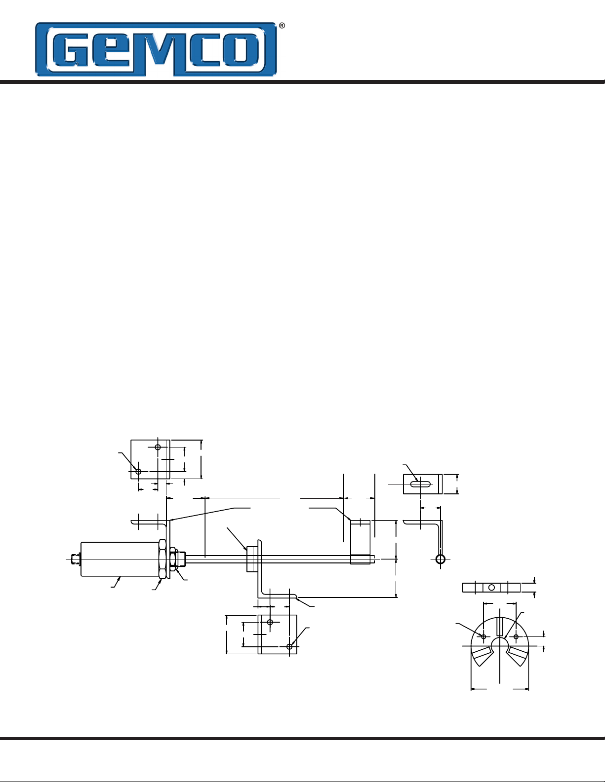
.28
2 PLACES
PROBE
NOTES: UNLESS OTHERWISE SPECIFIED
1. MOUNTING KITS FURNISHED WITH
MOUNTING BOLTS.
2. MOUNTING BRACKETS ARE MADE FROM
3/16" X 2" X3" STAINLESS STEEL.
1.75 HEX
1.00
2.00
1.25
.37
.44
NULL
3/4-16 JAM NUT
SUPPLIED W/PROBE
2.00
OPTIONAL
MAGNET
.62
1.25
STROKE DEAD
PROBE MOUNTING KIT
(P/N 949003)
1.00
MAGNET MOUNTING
KIT (P/N 949005)
.28
2 PLACES
Figure 2-1: Mounting the LDT
.28 X 1.03 SLOT
BAND
2.00
2.00
C
L
1.00
1.03
.187 THRU
(2 PLACES)
NOTE: USE THIS MAGNET WITH ROD
SUPPORT BRACKET SD0411100
MAT’L.: STAINLESS STEEL.
S
1.407
S
N
N N
2.50 REF.
.38
.75 THRU
.406
SS
STANDARD 4-HOLE MAGNET
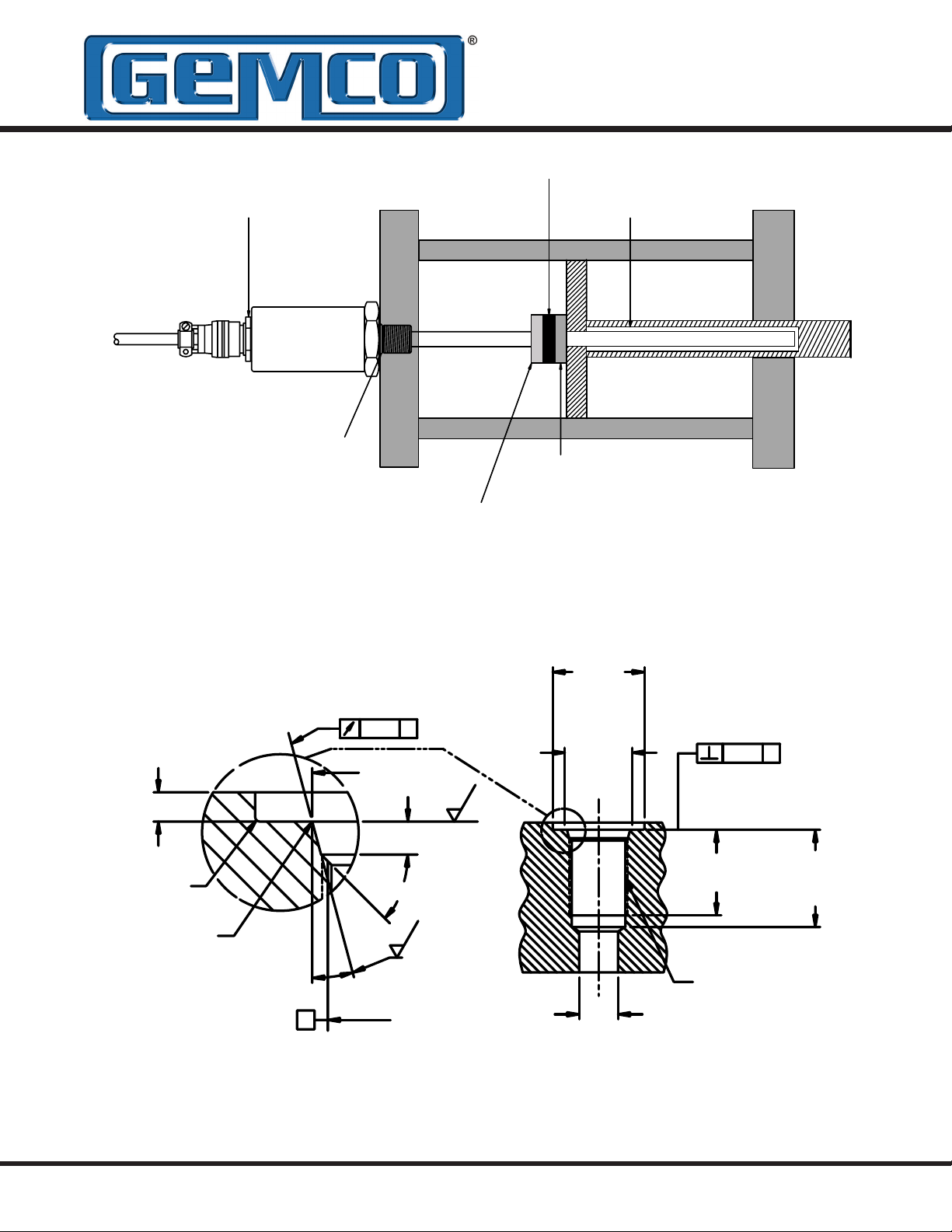
CABLE NUT
0.5" BORE MINIMUM
O-RING SEAL
MAGNET SPACER
OPTIONAL ROD BUSHING
Figure 2-2: Mounting LDT in a Hydraulic Cylinder
.094 MAX.
R.015
MAX.
R
.008
.004
RECOMMENDED
MIN. SPOTFACE
DIAMETER
.004 A
.813
+/-.002
SEE NOTE 1
MINIMUM
SEE NOTE 2
125
.106
+/-.008
45
125
15
A
PITCH
DIA.
SEE NOTE 4
Figure 2-3: Port Detail (SAE J1926/1)
1.18
.866
.500
REF.
.008 A
1.100
SEE NOTE 4
SEE NOTE 3
SEE NOTE 4
3/4-16 UNF-2B THREAD
1.250
Chapter 3: 952 Wiring Connections
Once the LDT has been installed, wiring
connections can be made. There are two groups of
connections that will need to be made. They are as
follows:
• Power Supply Connections
(including grounding and shielding)
• LDT Input/Output Connections
Power Supply/Ground Connections
The BlueOx standard cable is Alpha XTRA-GUARD
2 25110 SUPRASHIELD™, a multi-conductor cable
with a specially formulated polyurethane jacketing,
10 conductors of 22 ga, with an aluminum/polyester/
aluminum foil with drain wire plus an overall braid of
tinned copper shield. Cable O.D. is .30. Connector
option S, used only on the analog version, use an
industry standard 5 pin 12mm Euro style cordset
with a shield tied to the coupling nut. To reduce
electrical noise the shield must be properly used.
Connect the cable’s shield to the controller system
GND. The cable shield is not connected at the
transducer rod. Always observe proper grounding
techniques such as single point grounding and
isolating high voltage (i.e. 120/240 VAC) from low
voltage (15 - 26 VDC cables for digital LDTs) and
(13.5 - 30 VDC cables for analog LDTs).
WARNING: Do not use molded cordsets with
LED's!
It is preferable that the cable between the LDT and
the interface device be one continuous run. If you
are using a junction box, it is highly recommended
that the splice junction box be free of AC and/or
DC transient-producing lines. The shield should
be carried through the splice and terminated at the
interface device end.
NOTE: When grounding the LDT, a single earth
ground should be connected to the power supply
common (circuit ground). The LDT power supply
common (pin B) should be connected to the power
supply common (-) terminal. Pin C should be
connected to the power supply positive terminal (+).
The LDT cable shield should be tied to earth ground
at the power supply. The LDT analog common
should not be connected to earth ground and should
be used for connection to interface devices only. For
assistance, refer to your LDT’s wiring drawing in this
chapter.
Bipolar Wiring
If using the bipolar option, ensure that the power
supply is rated at ± 15 VDC at 100mA for each
polarity. The power supply should provide less than
1% ripple with 10% regulation. The power supply
should be dedicated to the LDT to prevent noise
and external loads from affecting the BlueOx
performance. See Figure 3-1. For more wiring
information, see wiring diagram in this chapter. Be
sure to identify the proper version of the LDT. A
linear supply should always be used with any LDT.
NOTE: Do not use Bipolar Wiring for 952A or 952
QD. See Section 3.4 for 952A wiring details and
Section 4.6: 952 QD Wiring Connections, for wiring
details.
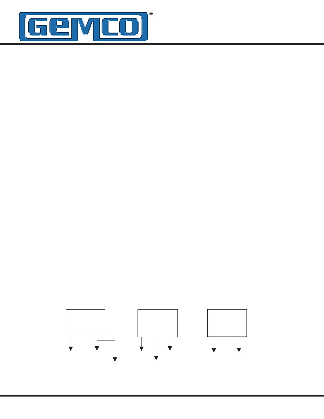
Unipolar Wiring
for Digital Style LDTs
Single ended
power supply
+15 to +26 VDC
+ COM
Pin C (red) Pin B (black)
Pin J (purple)
Bipolar Wiring
for Digital Style LDTs
Single ended
power supply
+15 to +26 VDC
+15 COM -15
Pin C (red)
Pin B (black)
Pin J (purple)
Unipolar Wiring for Analog
(10 Pin Connector E)
Pin C (red) Pin B (black)
Figure 3-1: Power Supply Wiring (Unipolar/Bipolar)
WARNING: Do not route the BlueOx cable near high voltage sources.
Style LDTs
Single ended
power supply
+13.5 to +30 VDC
+ COM

WARNING: Do not use the blue aluminum cover
of the head assembly or connector/cable nut
(either a 1 1/16" Amphenol connector or 1 3/16"
cable nut) to tighten the LDT within the bracket
(see Figure 2-1). This may damage the LDT
and will void your warranty. To tighten the LDT
within the bracket, use the 1.75" hex mounting
base on the head assembly.
At this point, the LDT should now be properly
installed inside the hydraulic cylinder. It may now
be necessary to assemble parts of the hydraulic
cylinder. For assistance in this task, refer to the
information provided by the cylinder manufacturer.
Unipolar Wiring
In order for the BlueOx to operate properly, the
LDT’s external power supply must provide a voltage
between +13.5 to +30 VDC for analog and +15 to
+26 VDC for digital style LDTs. The power supply
must be rated at 250mA minimum. The power
supply should provide less than 1% ripple with 10%
regulation.
The power supply should be dedicated to the
LDT to prevent noise and external loads from
affecting the BlueOx. When powering up more
than one BlueOx on a single power supply, each
BlueOx will draw no more than 250mA.
3.1: 952 Analog - V0/V1 (Voltage)
The 952A-V LDT generates a voltage output based
on position. The 952A BlueOx with analog output
offers 16 bits of resolution and is fully programmable
over the entire active stroke length of the LDT. Keep
in mind that there is a 2” Null area at the connector
end of the LDT and a 2.5” Dead area at the other
end of the LDT that the magnet must stay out of at
all times. The units come fully programmed from the
factory and do not require re-programming unless
desired. The analog units are 100% absolute and
will not lose programmed parameters on power loss.
3.2: 952 Analog - C4/C2 (Current)
The 952A-C LDT generates a current output based
on position. The 952A BlueOx with analog output
offers 16 bits of resolution and is fully programmable
over the entire active stroke length of the LDT. Keep
in mind that there is a 2” Null area at the connector
end of the LDT and a 2.5” Dead area at the other
end of the LDT that the magnet must stay out of at
all times. The units come fully programmed from the
factory and do not require re-programming on power
loss. The analog output is referenced to the analog
common terminal and should not be referenced to
any of the other common terminals. To wire the 952A
current LDT, see Section 3.4 and Figure 3-2. For
programming Zero and Span, refer to Section 3.9.
NOTE: 952A-C is current sourcing, which allows
the current to ow from the LDT into the user’s
equipment.
3.3: 952 Analog - D0/D1
(Differential Analog Output)
The 952A analog LDT’s are available with an
optional differential analog output. This feature is
hardware specic and must be specied at time of
order. The differential feature allows the distance
between two magnets to be measured. The magnets
must remain within the active stroke range at all
times and cannot be any closer than 2.5” to each
other. Keep in mind that there is a 2” Null area at the
connector end of the LDT and a 2.5” Dead area at
the other end of the LDT that the magnets must stay
out of at all times. The units come fully programmed
from the factory and do not require re-programming
unless desired. The analog units are 100% absolute
and will not lose programmed parameters on power
loss. For programming Zero and Span, refer to
Section 3.9.
The analog output is referenced to the analog
common terminal and should not be referenced to
any of the other common terminals. To wire the 952A
voltage LDT, see Section 3.4 and Figure 3-2. For
programming Zero and Span, refer to Section 3.9.
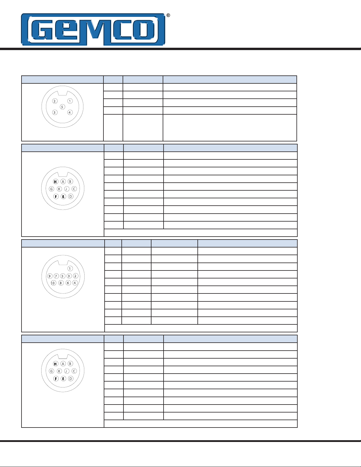
3.4: 952 - Analog Wiring
Connector Option S & C Pin # Wire Color Function
1 Brown Customer Supplied Power (+VDC)
2
1
5
3
4
LDT Connector View
Connector Option E Pin # Wire Color Function
B
A
H
G K J
F
C
D
E
LDT Connector View
2 White Program Input
3 Blue Power Supply Common
4 Black Position Output
5 Gray Position Common
A White Frame (No Connection)
B Black Power Supply Common
C Red Customer Supplied Power (+VDC)
D Green No Connection
E Brown Position Output
F Blue Program Input
G Orange No Connection
H Yellow 2nd Position Common
J Purple 2nd Power Supply Common
K Gray Position Common
Insulate and tie back any unused wires
Connector Option T & Q Pin # Wire Color Wire Color Striped Function
1 White White/Blue Stripe Power Supply Common
2 Brown Blue/White Stripe No Connection
3 Gray White/Orange Stripe Position Common
4 Pink Orange/White Stripe Position Output
5 Red White/Green Stripe Customer Supplied Power (+VDC)
9 7 5
10
1
2
3
4
6
8
6 Blue Green/White Stripe No Connection
7 Black White/Brown Stripe No Connection (Position output on pins 3 & 4)
LDT Connector View
MTS® Connector
Option RB & RC
8 Purple Brown/White Stripe No Connection (Position output on pins 3 & 4)
9 Yellow White/Gray Stripe No Connection
10 Green Gray/White Stripe Program Input
GEMCO Style 952A LDTs are programmable for zero and span. Position output is on pin 4
Connector Option M Pin # Wire Color Function
A White Power Supply Common
B
A
H
G K J
E
F
B
C
D
C Gray Position Common
D Pink Position Output
E Red Customer Supplied Power (+VDC)
F
G Yellow No Connection (Position output on pins 3 & 4)
LDT Connector View
MTS® Connector
Option RB & RC
H Green No Connection (Position output on pins 3 & 4)
J
K
GEMCO style 952A LDTs are programmable for zero and span. Position output is on Pin D
3.5: 952A (Analog)
Differential Input
Power +
Supply
_
Customer Supplied Power
Power Supply Common
Program Input
Single Ended Input
Power +
Supply
_
Customer Supplied Power
Power Supply Common
Program Input
NOTE: 952A-C is current
sourcing, which allows the
current to ow from the LDT
into the user’s equipment.
Figure 3-2: Current Sourcing
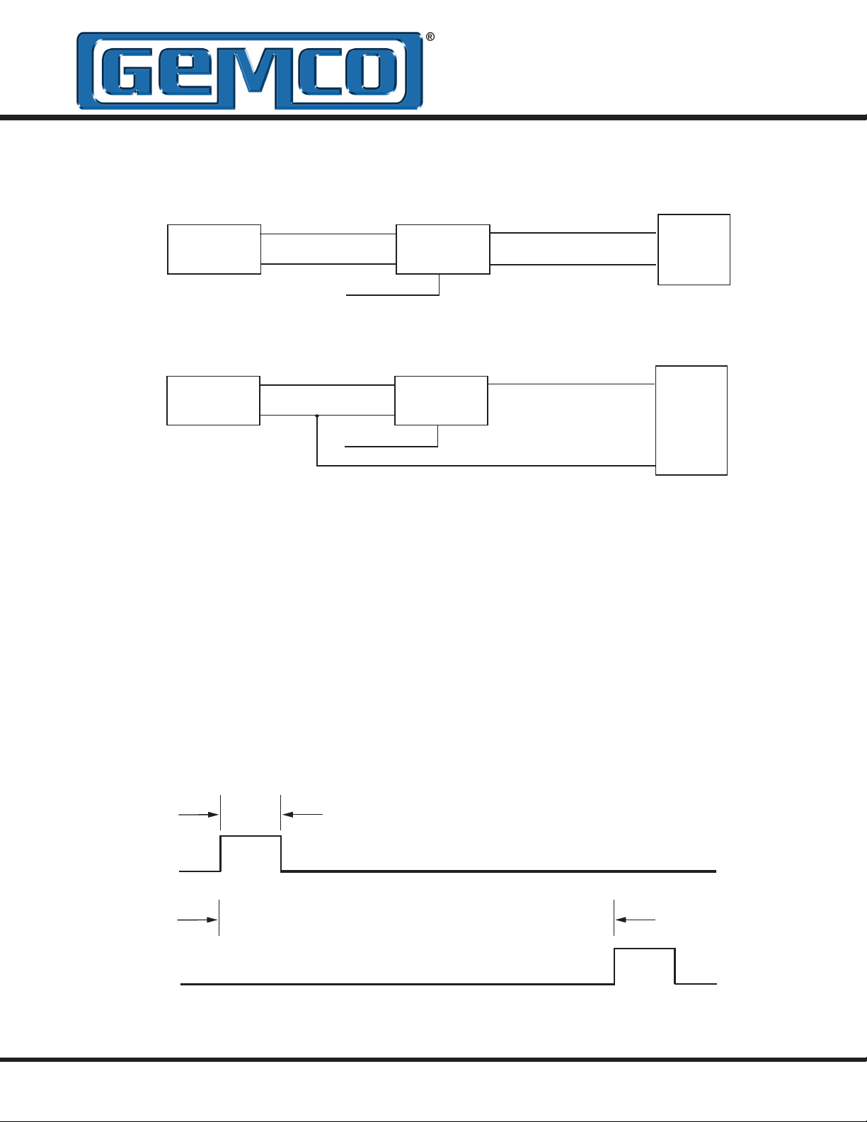
3.6: 952 CP (Control Pulse)
The control pulse signal interface of the BlueOx
digital output series is a differential RS-422 output.
The maximum cable length for the differential digital
LDTs is 1,500 feet. To initiate a start pulse, an
external device is used. This start pulse should be
1.0 microsecond in duration. After the start pulse
952A
LDT
952A
LDT
Position Output
Position Common
Position Output
+ Input
- Input
+ Input
Common
is received, the LDT will generate a stop pulse of
1.0 microsecond in duration. The time between
the leading edge of the start pulse to the leading
edge of the stop pulse is the proportional distance
between the magnet to the hex head. The order of
these two pulses is illustrated in Figure 3-3. To wire
the 952CP, see Figure 3-7. For proper grounding
information, see the beginning of this chapter.
+ INPUT (START PULSE)
TIME BETWEEN PULSES IS PROPORTIONAL TO
DISTANCE BETWEEN MAGNET AND HEX HEAD
+ OUTPUT (STOP PULSE)
Figure 3-3: 952CP Control Pulse
1 MICROSECOND (RECOMMENDED)
0.2 MICROSECONDS (MINIMUM)
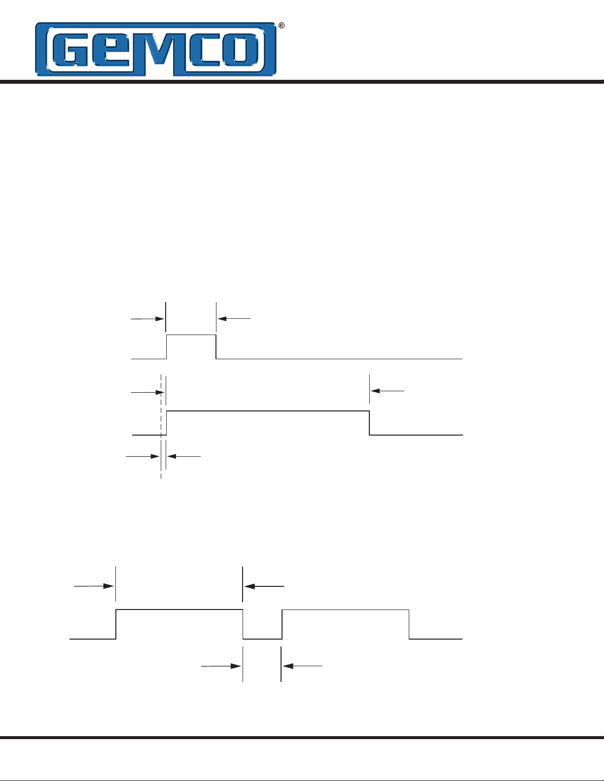
3.7: 952 VP (Variable Pulse)
The variable pulse signal interface of the BlueOx
digital output series is a pulse width modulated
signal (RS-422). The maximum cable length for the
differential LDTs is 1,500 feet. This LDT can also
be congured for external or internal interrogation.
External interrogation is when an external device
connected to the LDT generates a start pulse. This
start pulse should be a minimum of 1.0 microsecond
in duration. Within 50 nanoseconds after the leading
edge of the start pulse has been received, the LDT
will generate an output pulse. The duration of the
1 MICROSECOND (RECOMMENDED)
0.2 MICROSECONDS (MINIMUM)
INPUT (INTERROGATION)
WIDTH OF PULSE IS PROPORTIONAL TO
DISTANCE BETWEEN MAGNET AND HEX HEAD
output pulse is proportional to the distance from
the magnet to the hex head. The order of these two
pulses is illustrated in Figure 3-4. The 952VP can
also generate internal interrogations. This LDT will
continually output pulse width modulated signals.
As with a 952VP using an external interrogation,
the duration of this output pulse is proportional to
the distance from the magnet to the hex head. This
is illustrated in Figure 3-5. To wire the 952VP, see
Figure 3-7. For proper grounding information, see
the beginning of this chapter.
OUTPUT PULSE
WITHIN 50 NANOSECONDS AFTER INTERROGATION
TO DISTANCE BETWEEN MAGNET AND HEX HEAD
Figure 3-4: 952VP with External Interrogation
WIDTH OF PULSE IS PROPORTIONAL
TO DISTANCE BETWEEN MAGNET AND HEX HEAD
OUTPUT PULSE
Figure 3-5: 952VP with Internal Interrogation
LOW OUTPUT VARIES DEPENDING ON LENGTH
PROGRAMMED VIA DIP SW2 SWITCHES 1-6
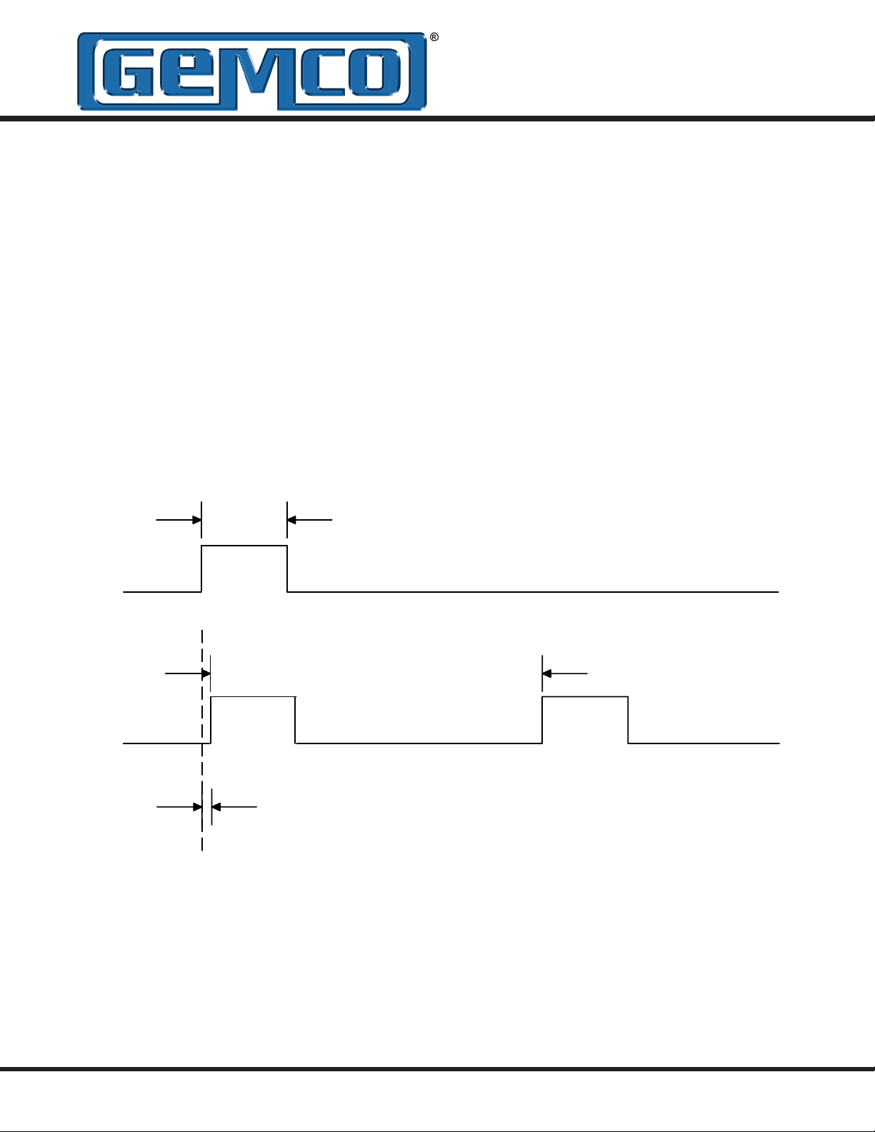
3.8: 952 RS (Start/Stop)
The start/stop signal interface of the BlueOx digital
output series is differential RS-422 output. The
maximum cable length for differential LDTs is 1,500
feet. To initiate a start pulse, an external device is
used. This start pulse should be a minimum of 1.0
microsecond in duration. Within 50 nanoseconds
after the leading edge of the start pulse, the LDT
will generate a start pulse of 1.0 microsecond
in duration. A stop pulse of 1.0 microsecond in
1 MICROSECOND (RECOMMENDED)
0.2 MICROSECONDS (MINIMUM)
duration will follow. The time it takes from the
leading edge of the start pulse to the leading edge
of the stop pulse is proportional to the distance
between the magnet to the hex head. The order of
these two pulses is illustrated in Figure 3-6. To wire
the 952RS, see Figure 3-7. For proper grounding
information, see the beginning of this chapter.
INPUT (INTERROGATION PULSE)
OUTPUT (START PULSE)
WITHIN 50 NANOSECONDS AFTER INTERROGATION
PULSE, START PULSE BEGINS
Figure 3-6: 952 RS Start/Stop Pulses
TIME BETWEEN PULSES IS PROPORTIONAL TO
DISTANCE BETWEEN MAGNET AND HEX HEAD
OUTPUT (STOP PULSE)

3.9: 952 CP, RS, VP Wiring
PINOUT FOR STANDARD
CIRCULAR CONNECTOR
AT TRANSDUCER HEAD
PIN-C
PIN-B
PIN-J
PIN-K
PIN-A
PIN-F
PIN-E
PIN-D
PIN-G
RED
BLACK
PURPLE
GRAY
WHITE
BLUE
BROWN
GREEN
ORANGE
+15 TO +26 VDC
POWER SUPPLY
POWER SUPPLY
COMMON
-15 VDC FOR BIPOLAR
POWER SUPPLY*
+INTERROGATION
-INTERROGATION
+GATE
-GATE
NO CONNECTION
NO CONNECTION
PIN-H
YELLOW
*For unipolar power supply, it is recommened
to connect this wire to power supply common
Figure 3-7: 952CP, VP, and RS Wiring Drawing
NO CONNECTION
Drawing No. Rev.
E0230900 0

3.10: Setting Zero & Span
Position (Analog LDTs Only)
The 952A-V LDT generates a voltage output based
on position. The 952A BlueOx with analog output
offers 16 bits of resolution and is fully programmable
over the entire active stroke length of the LDT. Keep
in mind that there is a 2” Null area at the connector
end of the LDT and a 2.5” Dead area at the other
end of the LDT that the magnet must stay out of at
all times. The units come fully programmed from the
factory and do not require re-programming unless
desired. The analog units are 100% absolute and
will not lose programmed parameters on power loss.
at the connector end of the LDT and a 2.5” Dead
area at the other end of the LDT that the magnet
must stay out of at all times. The units come fully
programmed from the factory and do not require
re-programming unless desired. The analog units
are 100% absolute and will not lose programmed
parameters on power loss.
The differential feature is user programmable for
ZERO and SPAN dimensions and can programmed
anywhere within the active stroke range. The zero
can either be programmed for fully open or closed.
To set the ZERO and SPAN position for the probe
follow these steps:
To set the ZERO and SPAN position for the LDT
follow these steps:
1. Apply power to the LDT.
2. Place magnet assembly where ZERO is to be
located, but within the active region of the probe.
3. Momentarily short the program input pin to the
power supply common.
4. Place magnet assembly where SPAN is to be
located, but within the active region of the probe.
5. Momentarily short the program input pin to the
power supply + pin (the maximum
distance must be within the active stroke range).
This completes the programming process.
3.11: Differential Analog Output
(Options D0, D1 or D2)
1. Apply power to the probe.
2. Move the magnets to the desired minimum
(ZERO) setting, but within the active region of
the probe.
3. Momentarily short the program input pin to the
power supply common.
4. Move the magnets to the desired maximum
(SPAN) setting, but within the active region of
the probe.
5. Momentarily short the program input pin to the
power supply + pin (the maximum
distance must be within the active stroke range).
This completes the programming process.
NOTE: The maximum programmmable stroke
range on units with the differential analog output is
2.5” less than the active stroke. Refer to your part
number label or Chapter 1 for active stroke range.
The 952A analog LDT’s are available with an
optional differential analog output. This feature is
hardware specic and must be specied at time of
order. The differential feature allows the distance
between two magnets to be measured. The
magnets must remain within the active stroke range
at all times and cannot be any closer than 2.5” to
each other. Keep in mind that there is a 2” Null area

Chapter 4: 952 QD Overview
4.1: Quadrature Output
A new method of interfacing magnetostrictive
transducers offers customers an interface as
common as analog with the speed and accuracy of
pulsed type signaling. The GEMCO 952 QD Linear
Transducer provides quadrature output directly from
the transducer to the controller (see drawing below).
The output from the transducer can be wired directly
to any incremental encoder input card, without
the need for a special converter module or PLC
interface card designed specically for use with a
pulse output magnetostrictive transducer.
The quadrature output provides absolute position
data in engineering units. This means that the
need for the calibration constant (wire speed)
programming has been removed, thereby
eliminating the possibility of having an improperly
calibrated system. The output signal wires are
driven by differential RS-422 line drivers, similar
to the drivers used in most magnetostrictive pulse
type transducers, providing a high degree of noise
immunity.
A unique feature of this transducer is a Burst mode
of operation. An input on the transducer triggers
a data transfer of all the incremental position data
relative to the transducer’s absolute zero position.
This can be used to achieve absolute position
updates when power is restored to the system or
anytime an update is needed to re-zero or home
the machine. Additionally, another input to the
transducer can be used to establish a Zero position
for the transducer.
4.2: Signal Connection
Application Note
Overview
This application note will attempt to clarify the type
of signals coming out of and going into the 952QD
quadrature probe.
Inputs
The quadrature probe has two inputs, the Zero and
Burst inputs. These inputs are single ended. That
is, the connection for each input consists of only
one wire, the corresponding signal wire. For these
(single ended) inputs, the signal is measured with
reference to the power supply ground, which is also
sometimes referred to as common.
The quadrature probe is available with either +24
VDC level signal thresholds or TTL level thresholds.
The signal voltage level required to activate the
input for the +24 VDC level signals is proportional
to the power supply voltage that the customer is
supplying to the probe. This level is approximately
41% of the power supply voltage. For example; if
the power supply voltage powering the probe is
exactly +24 VDC, the threshold voltage would be
about 9.84 volts.
The TTL level threshold signals are activated when
these inputs exceed the typical TTL level threshold,
which is 2.0 VDC.
Additionally, for the +24 VDC level signals, the
customer can specify either a sourcing or sinking
type of input. A sourcing input type is pulled high
internal to the probe. To activate a sourcing input,
the customer must pull the signal lower than the
threshold voltage to activate the input. A sourcing
input is usually driven by a sinking output or a
switch connected to ground. A sinking input type is
pulled low internal to the probe. To activate a sinking
input, the customer must pull the signal higher than
the threshold voltage to activate the input. A sinking
input is usually driven by a sourcing output or a
switch connected to the power supply.

It is important that the customer drive the signal
levels much greater or lower than the threshold
voltages. Asserting a signal with a voltage level
close to the threshold voltage could induce multiple
activations of that input (or none at all) and therefore
produce unexpected results or probe readings.
Outputs
The quadrature probe has three outputs, the A, B
and Z outputs. These outputs are differential (also
known as balanced). That is, the connection for
each output consists of two signal wires. These
are typically described as the + and - signals. For
example, the A channel consists of A+ and A-. The
same applies to the B and Z channels. For these
(differential) outputs, the signal is measured with
reference to the other signal (i.e. the difference or
differential). For example; if the A+ signal voltage
is greater than the A- signal, channel A is a logic 1.
Conversely, if the A+ signal voltage is lower than the
A- signal, channel A is a logic 0. Again, this applies
to the B and Z channels as well. Differential type
signals are much less prone to interference caused
by electrical noise or ground loops more often found
in single ended signal connections.
The differential outputs of the A, B, and Z channels
are at RS-422 signal levels. RS-422 is a well known
TIA/EIA standard and common interface type for
incremental encoders. The RS-422 receiver channel
(on the PLC or controller side of the connection)
typically has what is referred to as a termination
resistor connected across the + and - signal pins.
The value of the termination resistor is (by RS-422
specications) typically 100 ohms. However, some
receivers will work with greater resistance values
and some with no termination resistor at all. For
proper signal integrity, especially at higher data
rates (i.e. quadrature pulse frequency) a termination
resistor of no greater than 1Kohm is recommended.
given to these types of applications. It should be
noted the main signal requirements for an RS-422
signal is the differential voltage of the + relative to
the - signals and not necessarily the voltage level
of any one of these signals with respect to ground
(or common). To meet the RS-422 specication,
this differential voltage only needs to be +0.2 volts.
However, an RS-422 driver will typically drive either
the + or - signal to around 3.8 volts with respect to
ground. This voltage is more than sufcient to drive
TTL level inputs as well as other low level inputs.
The input voltage level specications of the PLC or
controller being used should be consulted for the
actual level required.
When using PLS’s or controllers that are not TTL
compatible output driver option L should be used.
Option L uses a 0L7272 line driver I.C. The output
from this driver will be 1 volt less than the LDT’s
input power.
When physically connecting a differential output to
a single ended input, only use the + signal, leaving
the - signal unconnected (do NOT connect the
- signals to ground). The A+, B+, and Z+ signals
should be connected to their corresponding inputs.
Insulate and tie back the - signals. See Figure 4-2,
Single Ended Interface.
Driving Single Ended Inputs
A differential output (i.e. our RS-422 drivers) can
also, for most but not all cases, be used to drive
single ended inputs. Special consideration must be

4.3: Quadrature Output
Resolution and Speed
The internal resolution of the 952 GEMCO Linear
Transducer is 0.001”. This would be represented
to the encoder input device by specifying an
output resolution of 1,000 cycles per inch for
the transducer. Although the typical resolution is
1,000 cycles per inch (CPI), the transducer can be
ordered with virtually any CPI setting.
For a typical rotary type shaft encoder with
incremental quadrature output, the output frequency
of the pulses is governed by the resolution of
the encoder (pulses per turn) and the rotational
speed (RPM) of the encoder. The output pulse rate
from the LDT transducer is xed and is controlled
internally and can be specied by the customer. The
output frequency must be specied so that it does
not exceed the maximum pulse rate of the encoder
input card the sensor is connected to. The output
pulse frequency range can be ordered from 10KHz
to 1MHz.
4.4: 952 QD Wiring Connections
be properly used. Connect the cable’s shield to
the controller system GND. The cable shield is
not connected at the transducer end. Always
observe proper grounding techniques such as
single point grounding and isolating high voltage
(i.e. 120/240 VAC) from low voltage (11-28 VDC
cables). Whenever possible, this cable should
be run in conduit by itself.
In order for the 952QD to operate properly, the
LDT's external power supply must provide a
voltage between +11 to +28 VDC. The power
supply must be rated at 250mA minimum. The
power supply should provide less than 1% rippel
and 10% regulations. (The power supply should
be dedicated to the LDT to prevent noise from
external loads from affecting the BlueOx).
Unipolar
Single ended
power supply
+11 to +28 VDC
Once the LDT has been installed, wiring
connections can be made. There are two groups
of connections you will need to make. They are as
follows:
• Power Supply Connections
(including grounding and shielding)
• LDT Input/Output Connections
Power Supply/Ground Connections
The BlueOx standard cable is Alpha XTRA-GUARD
2 25110 SUPRASHIELD™, a multi-conductor cable
with a specially formulated polyurethane jacketing,
10 conductors of 22 ga, with an aluminum/
polyester/aluminum foil with drain wire plus an
overall braid of tinned copper shield. Cable O.D.
is .30. To reduce electrical noise the shield must
+ COM
Pin C (red) Pin B (black)
Figure 4-1: Power Supply Wiring
WARNING: Do not route the BlueOx cable
near high voltage sources.
NOTE: The 952QD is only available in a
unipolar Supply.
4.5: Features
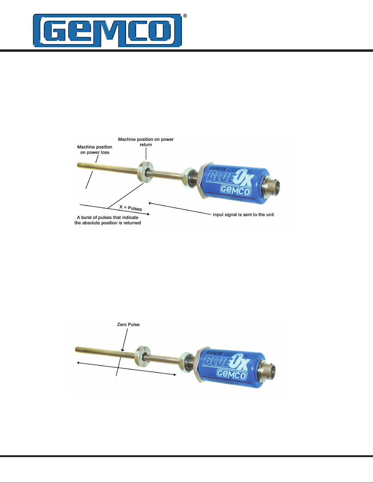
Burst Mode
Enables the system to be absolute even though
data transfer is through incremental method. In
the event of power failure, the controller can be
programmed to automatically send a signal to the
probe then the probe will respond with the current
position data. An input signal to the probe will cause
a burst of data, representing the absolute position,
to be fed back to the controller.
Zero Pulse
By sending a signal to the probe at any time in the
stroke, a new zero point can be established. When
using the burst input, the absolute position provided
will be relative to the established zero position.
In probes with volatile storage, the zero point will
The type of signal needed for the Burst / Zero inputs:
E = Sinking (PLC Sourcing Outputs)
C = Sourcing (PLC Sinking Outputs)
T = TTL
See Appendix C: Specications for more information
or see Figure 4-2.
be kept until a new zero pulse is sent or until the
probe loses power. Probes with nonvolatile storage
will store the zero position even if you lose power.
The nonvolatile zero can be set 100,000 times; the
volatile zero can be set an innite number of times.
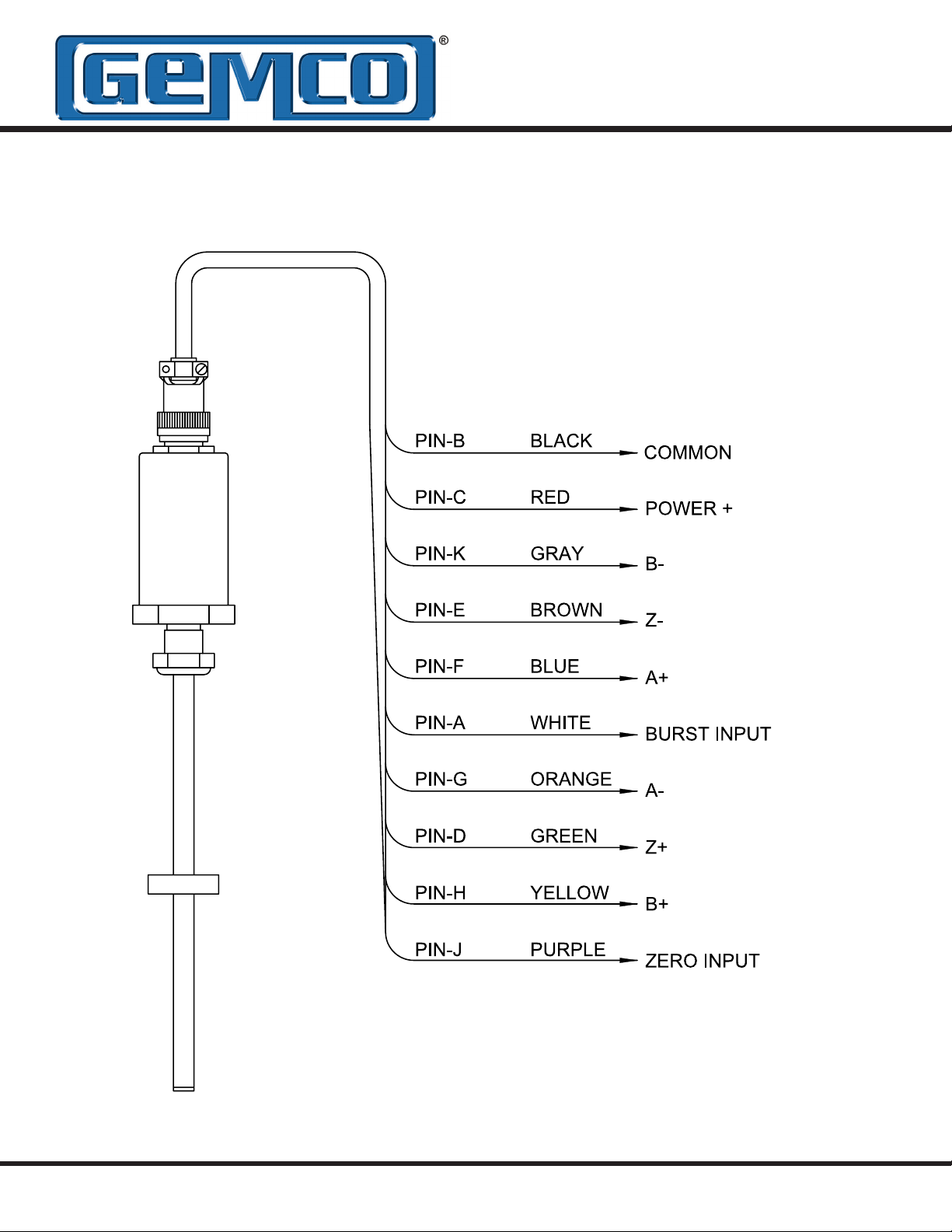
4.6: 952 QD Wiring Diagram
Figure 4-2: 952QD Wiring Diagram
Drawing E0237900
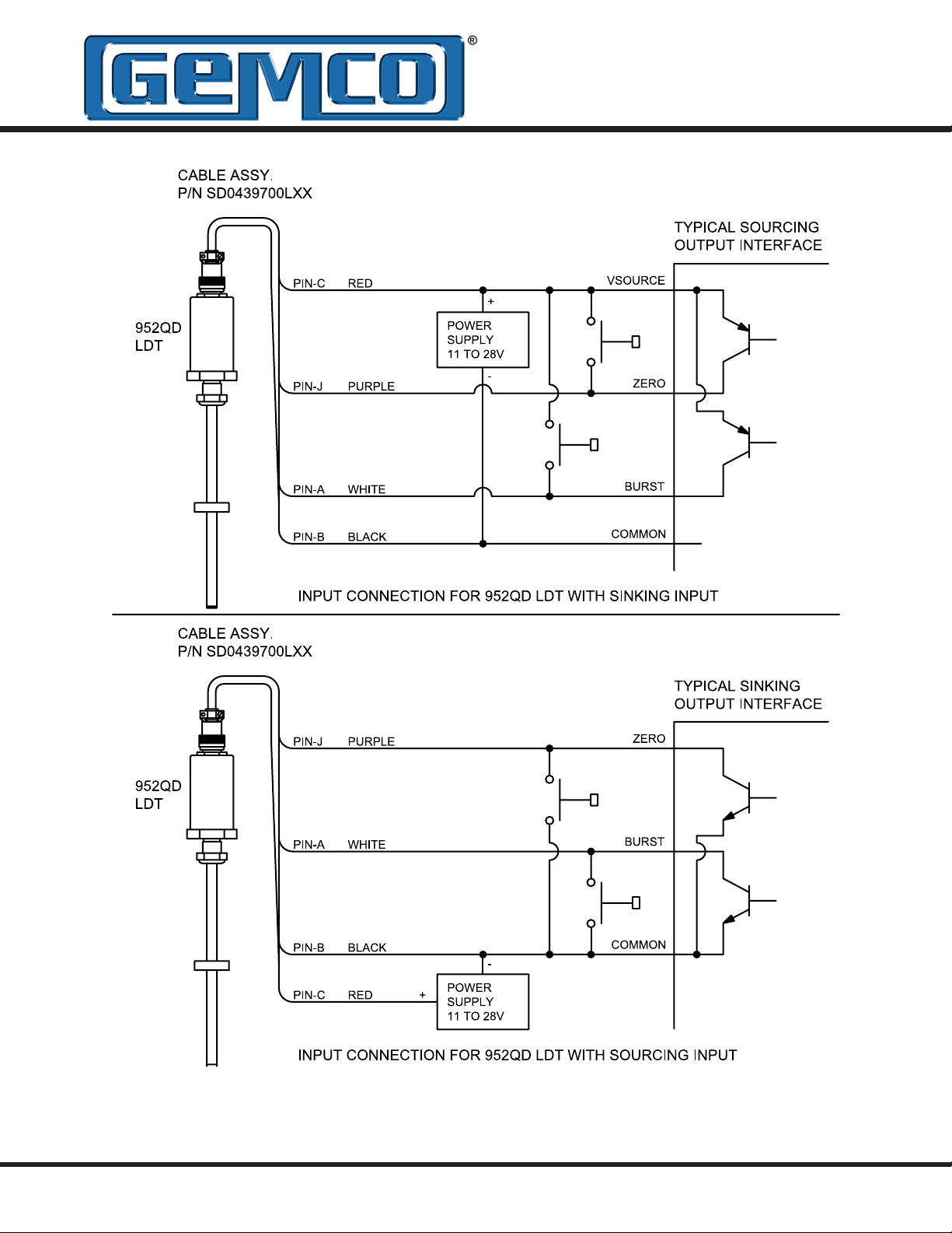
Figure 4-3: Input Signal Connections for 952 QD LDT
Drawing E0237700

Rt is the termination resistor typically used for differential connections. If these termination resistors
are not internal to the controller, they should be
installed externally at the connector. If these are
not specified or included with the controller, use 1K
Ohm resistors.
Figure 4-4: Output Signal Connections for 952 QD LDT
Drawing E0237600

4.7: 952 QD Frequency
Frequency or Pulse Rate
Selecting the proper frequency in the part number
and your controller is very important. The internal
clocks inside of the 952QD interrogates the LDT
and transmits the incremental pulses at a xed rate
of speed. The frequency or pulse rate of the 952QD
is factory set to 10KHZ - 1.00MHZ, consult part
numbers for your model. The input to the PLC or
display will determine the frequency needed.
Example: If your PLC High Speed counter card or
display accepts a 1MHZ encoder input the choices
are:
F1 = 10KHZ
F2 = 25KHZ
F3 = 50KHZ
F4 = 75KHZ
F5 = 100KHZ
F6 = 150KHZ
F7 = 250KHZ
F8 = 500KHZ
F9 = 1.00MHZ
NOTE: If your controller’s maximum input frequency
falls between two available frequencies, choose the
lower frequency.

Appendix A: Troubleshooting
A.1: Troubleshooting for 952 QD
Troubleshooting describes common problems
that may occur when installing the LDT and offers
possible solutions to these problems. If, after
reading this appendix, you are unable to resolve a
problem, contact factory. Troubleshooting is divided
into the following two groups:
• General Checks
• Power Supply
General Checks
Make sure that the magnet is located within
the LDT’s active stroke area. Captive magnet
assemblies should be positioned so that they can
move freely over the entire area of the active stroke
without binding or pushing on the rod. Non-captive
magnet assemblies should be situated so that the
magnet is no farther than 0.2" from the rod at any
point in the magnet assembly’s movement.
NOTE
magnetized) should be located no closer than 0.25"
from the magnet or LDT rod end. This includes
mounting brackets, magnet spacers, magnet
brackets, and mounting screws. Ferromagnetic
material can distort the magnetic eld, causing
adverse operation or failure of the LDT.
Check all LDT wires for continuity and/or shorts. It
is preferable that the cable between the LDT and
the interface device be one continuous run. If you
are using a junction box, it is highly recommended
that the splice junction box be free of AC and/or
DC transient-producing lines. The shield should
be carried through the splice and terminated at the
interface device end.
: Ferromagnetic material (material readily
Unipolar Power Supply Check
This section will help you to determine if your power
supply is adequate for the LDT to operate properly,
or if the LDT’s cable has a short or open.
In order for the BlueOx to operate properly, the
external power supply must provide a level between
+11 to +28 VDC. A power supply providing voltage
above this specied range may damage the LDT. A
power supply providing power below this specied
range will not be sufcient to power the LDT. When
powering more than one BlueOx on a single power
supply, remember that each BlueOx requires three
(3) watts of power maximum (1 watt typical). The
amount of current draw will vary based on the input
voltage used. To calculate the current draw for a
particular LDT, divide the LDT wattage by the input
voltage. For example, 3 watts divided by 24 VDC
equals 125mA.
If your LDT is not operating properly, the LDT’s
cable may have an open or short, or the power
supply is not supplying sufcient power. To verify
this, perform the following steps:
1. Turn the power supply off.
2. Remove the mating connector from the LDT
3. Turn the power supply on.
4. Using a digital voltmeter, check pins B (GND)
and C (+) from the mating end of the cable for a
level between +11 and +28 VDC.
NOTE: LDTs with potted cable assemblies should
be checked for proper voltage at the power supply
terminals. This cable assembly cannot be removed
from the LDT.
If reading is between +11 and +28 VDC, turn power
supply off and go to step 7. If reading is below +11
VDC, either your power supply is not providing

enough power or the LDT’s cable possibly has
a short/open. Readings of no voltage or minimal
voltage (less than 5 volts) may be due to a short/
open in the cable. If reading is not between +11
and +28 VDC, go to step 5. If reading is above +28
VDC, adjust power supply or replace.
5. Turn the power supply off.
6. Check the continuity of the individual wires of
the cable between the power supply and the
LDT. Check for continuity from one end of the
cable to the other. Also, verify that no shorts
exist between pins.
7. Reconnect the mating connector to the LDT.
8. Turn power supply on.
9. Using a digital voltmeter, check the power
supply’s + and - terminals for a voltage between
+11 and +28 VDC.
Low voltage readings may indicate a power supply
with a wattage (current) rating that is too low.
(Each LDT requires 3 watts). If the cabling checks
out in step 6 and your voltage is below +11 VDC,
check your power supply current rating. If voltage
is between +11 to +28 VDC and the LDT is still
inoperative, contact factory.

A.2: Troubleshooting for 952
Analog LDTs
Troubleshooting describes common problems
that can occur when installing the LDT and offers
possible solutions to these problems. If, after
reading this appendix, a problem is still unresolved,
please contact our technical support department.
Troubleshooting is divided into the following two
groups:
• General Checks
• Power Supply
General Checks
Make sure that the magnet is located within the
LDT’s active stroke area. Keep in mind that the
LDT is programmable over the entire active stroke
area. Refer to Section 3.9 for programming details.
Captive magnet assemblies should be positioned
so that they can move freely over the entire area of
the active stroke without binding or pushing on the
rod end. Non-captive magnet assemblies should be
situated so that the magnet is no farther than 0.2”
from the rod at any point in the magnet assembly’s
movement.
NOTE: Ferromagnetic material (material readily
magnetized) should be located no closer than 0.25”
from the magnet or LDT rod end. This includes
mounting brackets, magnet spacers, magnet
brackets, and mounting screws. Ferromagnetic
material can distort the magnetic eld, causing
adverse operation or failure of the LDT.
Unipolar Power Supply Check
This section will help you to determine if your power
supply is adequate for the LDT to operate properly,
or if the LDT’s cable has a short or open.
In order for the BlueOx to operate properly, the
external power supply must provide a level between
13.5 to 30 VDC. A power supply providing voltage
above this specied range may damage the LDT. A
power supply providing power below this specifed
range will not be sufcient to power the LDT. When
powering more than one BlueOx on a single power
supply, remember that each BlueOx requires three
(3) watts of power. The amount of current draw will
vary based on the input voltage used. To calculate
the current draw for a particular LDT, divide the LDT
wattage by the input voltage. For example, 3 watts
divided by 24 VDC equals 125mA.
If the LDT is not operating properly, the LDT’s cable
may have an open or short, or the power supply is
not supplying sufcient power. To verify this:
1. Turn the power supply off.
2. Remove the mating connector from the LDT.
3. Turn the power supply on.
4. Using a digital voltmeter, check across power
supply common and customer supplied power
(+VDC) on the mating end of the cable for a
level between 13.5 and 30 VDC.
NOTE: LDT’s with potted cable assemblies should
be checked for proper voltage at the power supply
terminals. This cable assembly cannot be removed
from the LDT.
Check all LDT wires for continuity and/or shorts. It
is preferable that the cable between the LDT and
the interface device be one continuous run. If you
are using a junction box, it is highly recommended
that the splice junction box be free of AC and/or
DC transient-producing lines. The shield should
be carried through the splice and terminated at the
interface device end.
If reading is between 13.5 and 30 VDC, turn power
supply off and go to step 7. If the reading is below
13.5 VDC, either the power supply is not providing
enough power or the LDT’s cable possibly has
a short/open. Reading of no voltage or minimal
voltage (less than 5 volts) may be due to a short/
open in the cable. If reading is not between 13.5
and 30 VDC, go to step 5. If reading is above 30
VDC, adjust power supply or replace.

5. Turn the power supply off.
6. Check the continuity of the individual wires
of the cable between the power supply and the
LDT. Check for continuity from one end of the
cable to the other. Also, verify that no shorts
exist between pins.
7. Reconnect the mating connector to the LDT.
A.3: Troubleshooting for 952 CP,
RS or VP LDTs
Troubleshooting describes common problems
that may occur when installing the LDT and offers
possible solutions to these problems. If, after
reading this section, there is still an unresolved
problem, contact factory. Troubleshooting is divided
into the following two groups:
Unipolar Power Supply Check
This section will help determine if the power supply
is adequate for the LDT to operate properly, or if the
LDT’s cable has a short or open.
In order for the BlueOx to operate properly, the
external power supply must provide a level between
+15 to +26 VDC. A power supply providing voltage
above this specied range may damage the LDT. A
power supply providing power below this specied
range will not be sufcient to power the LDT. When
powering more than one BlueOx on a single power
supply, remember that each BlueOx requires three
(3) watts of power. The amount of current draw will
vary based on the input voltage used. To calculate
the current draw for a particular LDT, divide the LDT
wattage by the input voltage. For example, 3 watts
divided by 24 VDC equals 125mA.
• General Checks
• Power Supply
General Checks
Make sure that the magnet is located within
the LDT’s active stroke area. Captive magnet
assemblies should be positioned so that they can
move freely over the entire area of the active stroke
without binding or pushing on the rod end. Noncaptive magnet assemblies should be situated so
that the magnet is no farther than 0.2" from the rod
at any point in the magnet assembly’s movement.
NOTE: Ferromagnetic material (material readily
magnetized) should be located no closer than 0.25”
from the magnet or LDT rod end. This includes
mounting brackets, magnet spacers, magnet
brackets, and mounting screws. Ferromagnetic
material can distort the magnetic eld, causing
adverse operation or failure of the LDT.
Check all LDT wires for continuity and/or shorts. It
is preferable that the cable between the LDT and
the interface device be one continuous run. If a
junction box is being used, it is highly recommended
that the splice junction box be free of AC and/or
DC transient-producing lines. The shield should
be carried through the splice and terminated at the
interface device end.
If the LDT is not operating properly, the LDT’s cable
may have an open or short, or the power supply is
not supplying sufcient power. To verify this, perform
the following steps:
1. Turn the power supply off.
2. Remove the mating connector from the LDT.
3. Turn the power supply on.
4. Using a digital voltmeter, check pins B (GND)
and C (+) from the mating end of the cable for a
level between +15 and +26 VDC.
NOTE: LDTs with potted cable assemblies should
be checked for proper voltage at the power supply
terminals. This cable assembly cannot be removed
from the LDT.
If reading is between +15 and +26 VDC, turn power
supply off and go to step 7. If reading is below
+15 VDC, either the power supply is not providing
enough power or the LDT’s cable possibly has
a short/open. Readings of no voltage or minimal
voltage (less than 5 volts) may be due to a short/
open in the cable. If reading is not between +15
and +26 VDC, go to step 5. If reading is above +26
VDC, adjust power supply or replace.

5. Turn the power supply off.
6. Check the continuity of the individual wires of
the cable between the power supply and the
LDT. Check for continuity from one end of the
cable to the other. Also, verify that no shorts
exist between pins.
7. Reconnect the mating connector to the LDT.
8. Turn power supply on.
9. Using a digital voltmeter, check the power
supply’s + and - terminals for a voltage between
+15 and +26 VDC.
Low voltage readings may indicate a power supply
with a wattage (current) rating that is too low. (Each
LDT requires 3 watts). If the cabling checks out in
step 6 and the voltage is below +15 VDC, check the
power supply current rating. If voltage is between
+15 to +26 VDC and the LDT is still inoperative,
contact factory.
Bipolar Power Supply Check
This section will help determine if the power supply
is adequate for the LDT to operate properly, or if the
LDT’s cable has a short or open.
In order for the BlueOx to operate properly, the
external power supply must provide +15 and -15
VDC ± 10%. A power supply providing voltage
above this specied range may cause damage to
the LDT. A power supply providing power below
this specied range will not be sufcient to power
the LDT. When powering more than one BlueOx
on a single power supply, each BlueOx requires a
maximum of 100mA from each supply rail.
NOTE
be checked for proper voltage at the power supply
terminals. This cable cannot be removed from the
LDT.
If the +15 is between +13.5 and +16.5 and the -15 is
between -13.5 and -16.5, turn the power supply off
and go to step 7. If the reading is below ±13.5 VDC,
either the power supply is not providing enough
power or the LDT’s cable has a short. Readings of
no voltage or minimal voltage (less than 5 volts)
may be due to a short in the cabling. If reading is
not +15 and -15 VDC, go to step 5.
Low voltage readings may indicate a power supply
with a wattage (current) rating that is too low. (Each
LDT requires 100mA from both the + and - supply
rails.). If the cabling checks out in step 6 and the
voltage is below ±15 VDC ±10%, check the power
supply current rating. If voltage is at ±15 VDC ±10%
and the LDT is still inoperative, contact factory.
: LDTs with potted cable assemblies should
5. Turn the power supply off.
6. Check the continuity of the individual wires of
the cable between the power supply and the
LDT. Check for continuity from one end of the
cable to the other. Also, verify that no shorts
exist between pins.
7. Reconnect the mating connector to the LDT.
8. Turn the power supply on.
9. Using a digital voltmeter, check the power
supply’s +15 and -15 terminals for the proper
voltage levels, ±15 VDC ±10%.
If the LDT is not operating properly, the LDT’s cable
may have an open or short, or the power supply is
not supplying sufcient power. To verify this, perform
the following steps:
1. Turn the power supply off.
2. Remove the mating connector from the LDT.
3. Turn the power supply on.
4. Using a digital voltmeter, check pins B (GND)
and C (+) from the mating end of the cable for
+15 VDC. Also, check from pins B (GND) to J (-)
for -15 VDC.

Appendix B: Ordering Information
B.1: Analog Part Numbering
952A
V0
0120
Analog BlueOx
Output Type
V0 = 0 - 10 VDC
V1 = 10 - 0 VDC
C4 = 4 - 20mA
C2 = 20 - 4mA
D0 = Differential 0 - 10 VDC*
D1 = Differential 4 - 20mA *
*Analog differential output is the difference between two magnets.
Minimum distance is 2.5”.
Stroke in Inches
Insert stroke in inches to 0.1 inch. Enter as a four-place number.
Example: 12.0 in stroke entered as 0120. To convert a metric stroke in
millimeters, multiply millimeter value by 0.03937 to arrive at inch value.
On differential output units (D0 or D1) the active measuring range will
be 2.5” less than the specied stroke due to the 2.5” magnet to magnet
separation distance requirement.
Null Zone
X _= Standard 2 inch Null
N = Insert non-standard Null over 2 inches
Dead Zone
X = Standard Dead Zone of 2.5 inches
D _= Insert non-standard Dead Zone over 2.5 inches
X EX
Connector Style
S = Standard 12mm 5 pin Euro Connector ( CE Approved )
E = Environmental MS Connector*
C _= Potted Pigtail Cable Assembly. Insert Pigtail length in feet.
T = Threaded Metal Connector (ts MTS® - RB on Tempo II
Q = Bayonet Style Connector (ts MTS® - RC on Tempo II
M = 1/4 Turn Quick Disconnect (ts MTS® - MS on Tempo II
Consult factory for other connector options.
TM
TM
* If option S or E (environmental connector) is selected,
mating connector and/or pigtail must be ordered
separately. NOTE 1: On unsupported stroke lengths
greater than 4 feet, rod support bracket(s) and a special
magnet should be used. NOTE 2: Specify magnet as
separate line item (standard magnet is SD0400800).
MTS® is a Registered Trademark of MTS Systems Corp.
or III)
or III)
TM
or III)

B.2: Digital Part Numbering
952VP 0120
X
CP = Control Pulse
VP = Variable Pulse
RS = RS422 Start/Stop Pulse
Stroke in Inches
Insert stroke in inches to 0.1 inch. Enter as a four-place
number. Example: 12.0 in stroke entered as 0120. To
convert a metric stroke in millimeters, multiply millimeter
value by 0.03937 to arrive at inch value.
Null Zone
X = Standard 2 inch Null
N _= Insert non-standard Null over 2 inches
Dead Zone
X = Standard Dead Zone of 2.5 inches
D _= Insert non-standard Dead Zone over 2.5 inches
Connector Style
E = Environmental MS Connector*
C _= Potted Pigtail Cable Assembly. Insert Pigtail length in feet.
T = Threaded Metal Connector (ts MTS - RB on Tempo II
Q = Bayonet Style Connector (ts MTS - RC on Tempo II
M = 1/4 Turn Quick Disconnect (ts MTS - MS on Tempo II
TM
or III) (RS and VP only)
TM
or III) (RS and VP only)
TM
or III) (RS and VP only)
X E
I
001
Interrogation Mode (with VP only)
I = Internal Interrogation
E = External Interrogation
Recirculations Required (with VP only)
001 (standard) to 127
* If option E (environmental connector) is selected, mating connector
and/or pigtail must be ordered separately. NOTE 1: On unsupported stroke
lengths greater than 4 feet, rod support bracket(s) and a special magnet
should be used. NOTE 2: Specify as magnet separate line item (standard
magnet is SD0400800).
WARNING: Not for use with a GEMCO interface.

B.3: Quadrature Part Numbering
952QD 0120
BlueOx with
Quadrature Output
Stroke in Inches
Insert stroke in inches to 0.1 inch. Enter as a four-place number. Example:
12.0 in stroke entered as 0120. To
convert a metric stroke in millimeters,
multiply millimeter value by 0.03937 to
arrive at inch value.
Null Zone
X = Standard 2 inch Null
N _= Insert non-standard Null over 2
inches.
Dead Zone
X = Standard Dead Zone of 2.5 inches
D _= Insert non-standard Dead Zone over 2.5 inches
Connector Style
E = Environmental MS Connector*
C _= Potted Pigtail Cable Assembly. Insert Pigtail length
in feet.
Output Resolution
Cycles per inch, maximum internal resolution is 0.001 inches
1000 standard (available range is 0001 through 9999)
X X
E
1000
E F7
M1
N
D
X
Input Type
E = Sinking (typically used with sourcing output type)
C = Sourcing (typically used with sinking output type)
T = TTL Level
Quadrature Cycle Output Frequency Range
F1 = 10 KHz F2 = 25 KHz F3 = 50 KHz F4 = 75 KHz
F5 = 100 KHz F6 = 150 KHz F7 = 250 KHz F8 = 500 KHz F9 = 1.00 MHz
Output Mode
M1 = X1 quadrature, Consult factory for other output modes.
Zero Offset Storage
V = Volatile (non retentive)
N = Nonvolatile (retentive, 100,000 storage cycles maximum).
Output Drivers
D = Differential RS422 line driver, TTL compatible
L = Differential line driver 10 - 30 VDC, V out = V in (LDT Power) -1 volt
Options
X = None
* If option E (environmental connector) is selected,
mating connector and/or pigtail must be ordered separately.
NOTE: Consult factory for
custom congurations.

Appendix C: Specications
General Specications
Rod End 316 Stainless Steel, 0.405" (10.29 mm) outer diameter
Mounting Hex 316 Stainless Steel, 1.75" (44.45 mm) across ats
Mounting Threads 3/4-16 UNF-2B x 1.00" (25.4 mm) with ESNA Jam Nut and O-ring seal
Head Assembly Thick Wall Aluminum Cover with Viton O-ring Standard Gasket Seal at the Base and
Connector Exit, NEMA 4 (Type 6 optional, consult factory).
Connector 1/4 turn MS-Style Standard (quick connect/disconnect) Connector. Consult factory for
other options
Displacement Up to 168"
Electromagnetic
Compatibility
Dead Band 2.50" (63.5 mm) standard
Null Zone 2.00" (50.8 mm) standard
Head Enclosure 3" (76.20 mm) high with 1.75" (44.45 mm) diameter; hex and cover are NEMA 4
Input Voltage
Unipolar
Bipolar
Current Draw
Unipolar
Bipolar
(Digital LDT Only)
Nonlinearity Less than +/- 0.05% *
Repeatability +/–0.001% of full stroke or 0.002" (0.0254 mm), whichever is greater.
Hysteresis +/- 0.02% *
Temperature
Coefcient LDT
Operating
Temperature
Head (Electronics)
Guide Tube
Storage Temperature -40° to 185° F (-40° to +85° C)
Operating Pressure 5000 psi Operational, 10,000 psi Spike
Shock & Vibration
Vibration
Shock
* Specications are based on a typical 36" stroke length.
IEC 801-2, Level 3 (Electrostatic discharge requirements)
IEC 801-4, Level 3 (Electrical fast transient/burst requirements)
Electrical Specications
Analog: 13.5 to 26.4 VDC
Digital: 13.5 to 26.4 VDC
±15 VDC ±10% (Digital Units Only)
Quadrature: 11 to 28 VDC
3 watts maximum, 200mA at 15 VDC (1 Watt, Typical)
100mA maximum @ +15 VDC, 100mA maximum @ -15 VDC
Less than 0.00011 in./Degree F + [3 PPM/Degree F/in. of Full Stroke] (Less than 0.00503
mm/Degree C + [5.4 PPM/Degree C/mm of Full Stroke]).
-40° to +158° F ( -40° to +70° C)
-40° to +220° F (-40° to +105° C)
30 Grms.
2000 G.
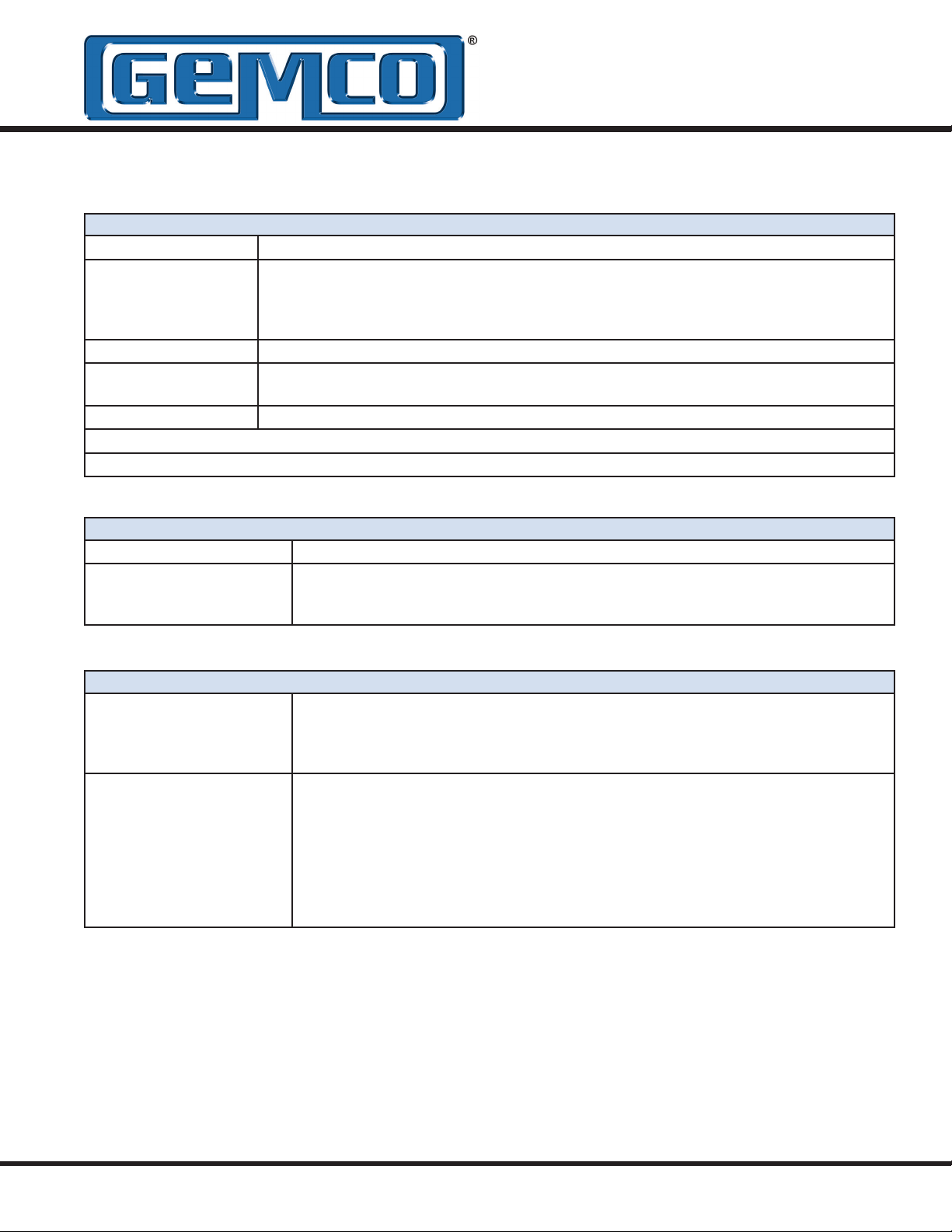
Analog Specications
Analog Output Drift 10ppm/Degree F (18ppm/DegreeC)
Analog Output
Loading
Voltage Output Minimum Load Resistance: 2Kohm
Current Output Maximum Load Resistance: (Vin - 2)/0.02
Output Current: Guaranteed 6mA minimum for voltage units
Analog Ripple <1 mV maximum (position output)
Update Time 1mS (stroke lengths 1" to 50")
2mS (stroke lengths 51" to 100")
3mS (stroke lengths 101" to 150")
4mS (stroke lengths 151" to 168")
Position Output 0 - 10 VDC, 16 Bits (65,535) resolution 4 - 20mA, 16 Bits (65,535) resolution
CE Approved with Connector Option "S" Only
Output May Vary by 0.1% when Subjected to Severe Levels of Electrical Noise
Digital Specication
Update Time Controller Dependent
Digital Output CP RS-422 Control Pulse
VP RS-422 Pulse Width Modulated
RS RS-422 Start/Stop
(BCD, Binary, or Gray Code Outputs
available from 2120 Interface Module.)
Quadrature Specication
Digital Output 1) Quadrature A: RS-422 differential
2) Quadrature B: RS-422 differential
3) Zero (index) position: RS-422 differential
maximum 5V, minimum 2V into a 50Ω load
Digital Input 1) Zero position set: 5-30V Source or Sink
2) Burst mode input: 5-30 Source or Sink
Input impedance: 5KΩ
Sink threshold: Input < 0.41 x VPS. (Power Supply Voltage)
i.e.: 0.41 x 24VDC Power Supply = <9.84VDC
Source threshold: Input > 0.41 x VPS. (Power Supply Voltage)
i.e.: 0.41 x 24VDC Power Supply = >9.84VDC
TTL threshold: Input > 2.1V

Glossary
Active Stroke Area
Burst Input
Bipolar Power Supply
Connect/Disconnect
Connector
Dead Band
External Device
External Interrogations
Head Assembly
Incremental
Input Type
Internal Interrogations
Jam Nut
LDT
Magnet Assembly
Mounting Hex Base
Non-Volatile
Null Zone
Output Resolution
Potted Cable Assembly
Quadrature
Quadrature Cycle
Output Frequency
The area designated by the operator on the rod on which the magnet assembly moves.
An input signal to the probe will cause a burst of data, representing the absolute position to
be fed to the controller. NOTE: This only applies to the quadrature LDT.
A power supply that provides both +15 and -15 VDC.
A connector which can be quickly connected or disconnected from the LDT’s terminals by
turning the connector 1/4 of a turn and then pulling.
An area usually 2.5” from the end of the rod where sensing of the magnet is not possible.
A device wired to the LDT which generates external interrogations.
Pulses sent by an external device to the LDT, usually to initiate a pulse sequence.
An enclosure used to house the LDT’s electronic components.
A relative position feedback device whose signal is always referenced to the zero position.
The LDT produces a digital, square wave pulse train that is fed into an up/down counter chip
or clock to derive position.
Used on 952 QD to determine input type for Burst and Zero modes. ie; sinking, sourcing or
TTL.
Pulses generated by the LDT usually to initiate a pulse sequence.
A nut which screws onto the threads protruding from the hex mounting base. This nut is
used to secure the head of the LDT to the user’s mounting xture.
Linear Displacement Transducer
A non-ferrous ring that moves across the LDT’s rod end.
A non-ferromagnetic base of the mounting hex. This point is where the mounting hex
threads begin to protrude from the mounting hex. This hex can be used when tightening the
LDT into a bracket.
Position is held in memory and will not be lost on power down.
An area usually covering 2.0” on the rod beginning at the threads protruding from the hex
mounting base; the area on the rod end which follows the standard null going toward the tip
of the rod end is the active stroke area.
Used in 952 QD to determine amount of pulses per inch.
An interface cable that is permanently installed on the LDT at the factory.
Two output channels out of phase by 90 electrical degrees.
The frequency at which the pulse rate is transmitted out of a quadrature probe.

Recirculations
Return (Stop) Pulse
Rod
RS422 Differential
Start Pulse
Stop Pulse
Unipolar Power Supply
Volatile
Wire Speed
Zero Pulse
The method used to improve the resolution of a system using a digital LDT.
of a pulse width output is multiplied by a specied factor (from 1-127). This multiplication
provides more counting time for the counter in the customer’s electronics, thus improving
the resolution. The only disadvantage to higher recirculation numbers is the time needed to
process the signals.
A pulse generated by the BlueOx to determine the location of the magnet assembly on the
rod end.
A stainless steel tube on which the magnet assembly travels.
Differential line driver.
A pulse generated by either an external device or the LDT to start a pulse sequence.
(See Return Pulse)
A power supply that provides a single voltage.
Position held in memory that is lost on power down.
The average time it takes a pulse to travel one inch on the wire.
By sending a signal to the probe at any time in the stroke a new zero point can be established. (952 QD only)
The On time
 Loading...