

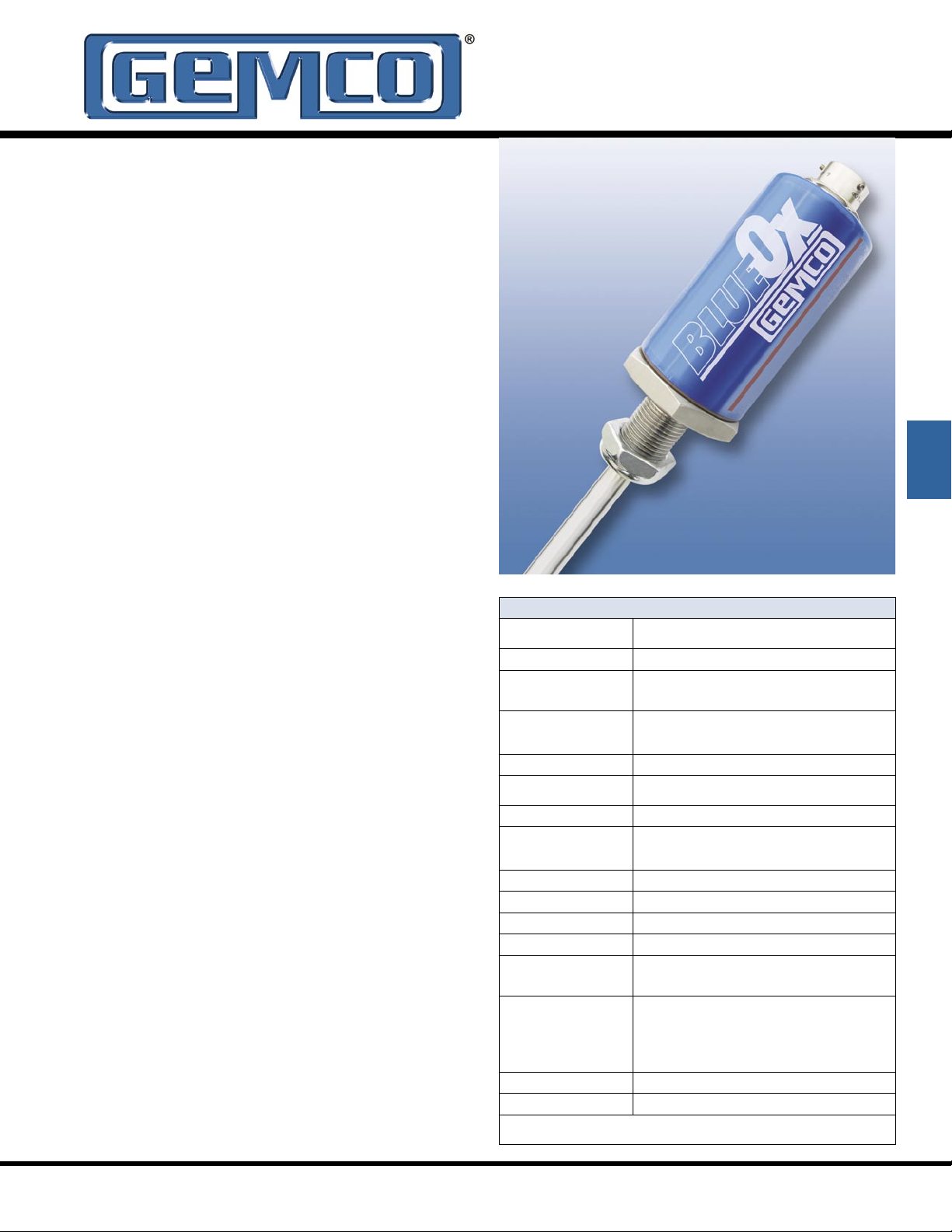
Magnetostrictive LDT
for High Shock and Vibration Areas
Gemco brand position sensing products have been
known for survival in harsh industrial environments.
We have taken over twenty years experience in
magnetostrictive linear sensors and married it with
our understanding of rugged industrial sensors to
develop the BlueOx LDT as the industry’s first truly
rugged magnetostrictive linear transducer.
The BlueOx LDT is lab tested and field proven to
stand up to high shock and vibration. With test
results of 2,000 Gs of shock and 30 Gs of random
vibration without false signals or mechanical
damage, the BlueOx LDT is ready to perform on the
most demanding applications.
In addition to its ability to withstand shock and
vibration, the BlueOx LDT is rugged in other ways.
Sensing tube construction is welded stainless
steel, suitable for insertion in 5000 PSI hydraulic
cylinders. The electronics are enclosed behind an
aluminum housing with O-ring seals for IP67 indoor
applications (Type Nema 6 rating and stainless steel
covers and connectors are available as a special
option).
The 952 BlueOx is available with Analog, Control
Pulse, Variable Pulse or RS422 Start/Stop outputs.
The 952 is compatible with PLC interface cards
and our 1746 LDT Interface Card. The 16 bit
resolution analog output is programmable over the
entire active stroke length. The units can easily be
changed in the field from a 0 - 10 VDC to a 10 - 0
VDC or a 4 - 20mA to a 20 - 4mA. As an added
feature, the optional differential analog output allows
the distance between two magnets to be measured.
The BlueOx, with its high resolution and rugged
construction, is at home in heavy duty areas such as
lumber mills, steel mills, stamping plants, assembly
automation, material handling, robotics and any
other industry where highly accurate and reliable
continuous linear position sensing is needed.
952 BlueOx
Specifications
Input Voltage
Current Draw
Output
Resolution
Internal
Analog Output
Linearity
Repeatability
Hysteresis
Operating Temperature
Head Electronics
Guide Tube
Operating Pressure
Span Length
Null Zone
Dead Band
Connectors
Update Time
Analog
Digital
Enclosure
Approvals
Analog: 13.5 to 30 VDC
Digital: 13.5 to 26.4 VDC, or +/- 15 VDC
< 200mA at 15 VDC
Analog: 0 to 10 VDC or 10 to 0 VDC, 4 to 20mA or 20 to 4mA
Digital: Start/Stop, Control Pulse or Pulse-Width Modulated/
Variable Pulse (PWM/VP)
0.001”
16 Bit (1 part in 65,535)
+/-0.05% of Full Scale
+/-0.006% of Full Scale
(+/- .002 inch min.)
+/-.02% of Full Scale
-40° to 158° F (-40° to 70° C)
-40° to 221° F (-40° to 105° C)
5000 psi Operational, 10,000 psi Spike
2” to 168”
2”
2.5”
12mm Micro 5 Pin, CE Approved (Analog Only),
10 Pin 1/4 Turn MS Connector, Potted Pigtail Assembly,
Optional Temposonics II & III Connectors
1ms (Stroke Lengths 1” to 50”)
2ms (Stroke Lengths 51” to 100”)
3ms (Stroke Lengths 101” to 150”)
4ms (Stroke Lengths 151” to 168”)
Controller Dependent
IP67
CE ( Analog 12mm Micro 5 Pin Connector Only )
Specifications are subject to change without notice.
Specifications are based on a typical 36” LDT .
952
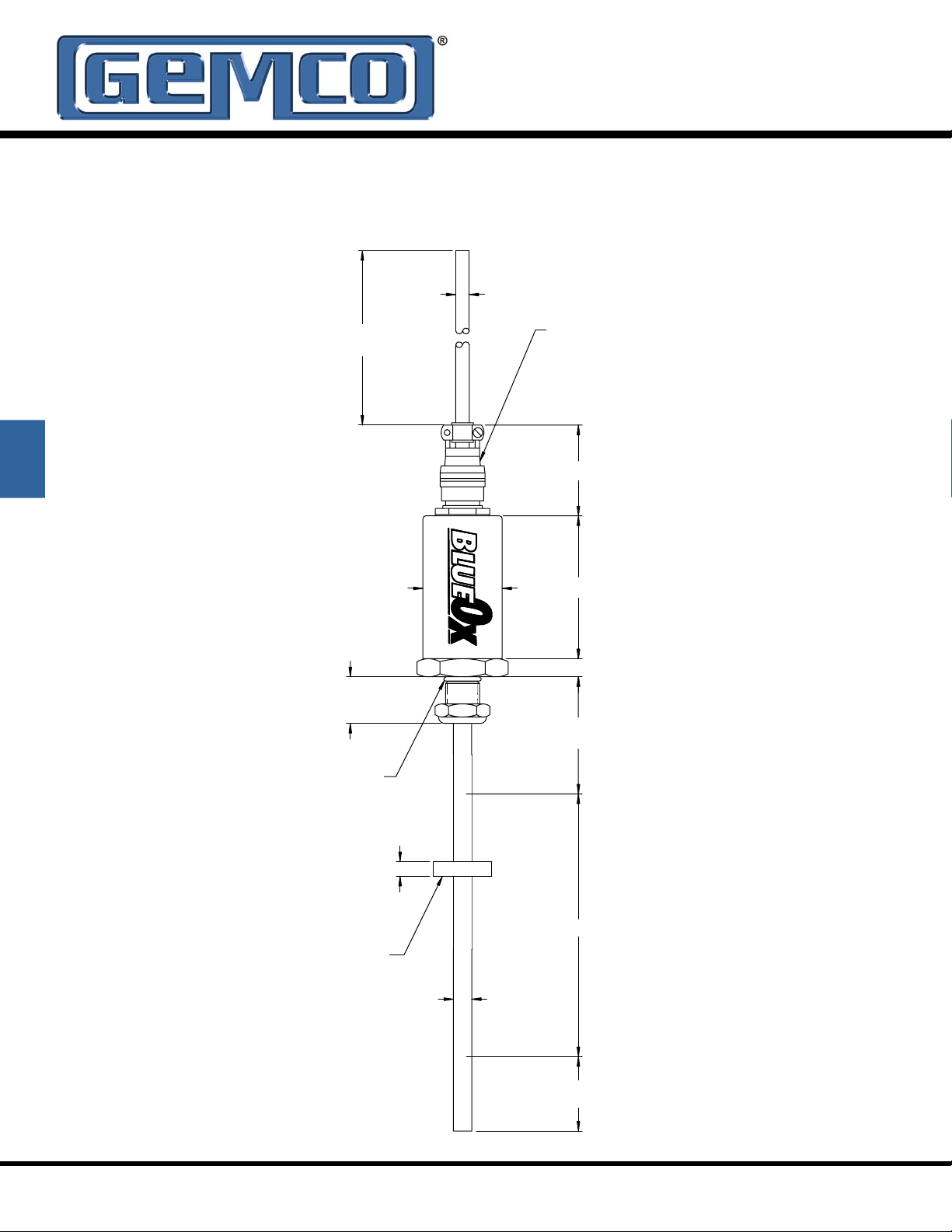
2.00
DEAD BAND
3/4-16
X 1.00 THRD.
W/ ESNA JAM NUT
CABLE
1.75 DIA.
COVER &
.31
.4O DIA.
TUBE
1.28 DIA.
MAGNET
TUBE BOSS SEAL.
.30 DIA.
NULL
STROKE
2.50
3.00
.38
METAL CIRCULAR
CONNECTOR
2.00
PIGTAIL
VITON O-RING
FOR 1/2" DIA.
HEX
952 BlueOx
Dimension Drawing
952
952A BlueOx
WHITE
BLUE
BROWN
GRAY
RED
BLACK
PROGRAM INPUT
NO CONNECTION
POSITION OUTPUT
POSITION COMMON
+15/+30 VDC
POWER SUPPLY
ORANGE
NO CONNECTION
PIN-OUT FOR STANDARD
CIRCULAR CONNECTO
AT TRANSDUCER HEAD
GREEN
YELLOW
PURPLE
NO CONNECTION
2nd POSITION COMMON
2nd POWER SUPPLY
COMMON
POWER INPUT
COMMON
PIN-B
PIN-C
PIN-K
PIN-E
PIN-F
PIN-A
PIN-G
PIN-D
PIN-H
PIN-J
Part Numbering
952A
V0
0120
Analog BlueOx
Output Type
V0 = 0 to 10 VDC
V1 = 10 to 0 VDC
C4 = 4 to 20mA
C2 = 20 to 4mA
Stroke in Inches
Insert stroke to 0.1” as a four-place number,
enter 12.0” stroke as 0120; to convert
metric strokes, multiply millimeter value by
0.03937 for inch value
Null Dimension
X_= Standard 2 inch Null
N = Insert non-standard Null over 2 inches
(add non-standard portion of Null length to stroke length to calculate list price)
Dead Band
X = Standard Dead Band of 2.5 inches
D_= Insert non-standard Dead Band over 2.5 inches
(add non-standard portion of Dead Band length to stroke length to calculate list price)
Connector
S = Standard 12mm 5 pin Euro connector ( CE Approved )
E = Environmental MS connector*
C_= Potted pigtail cable assembly, insert pigtail length in feet
T = Threaded metal connector (fits MTS - “RB” on Tempo II
M = 1/4 turn quick disconnect (fits MTS - “MS” on Tempo II
Consult factory for other connector options
D0 = Differential 0 to 10 VDC*
D1 = Differential 4 to 20mA *
*Analog differential output is the difference
between two magnets, minimum distance is
2.5”
TM
or III)
TM
or III)
X EX
952
* If option S or E (environmental connector) is
selected, mating connector and/or pigtail must be
ordered separately.
Note 1: On unsupported stroke lengths greater than
4 feet, rod support bracket(s) and a special magnet
should be used.
Note 2: Specify magnet as separate line item
(standard magnet is SD0400800).
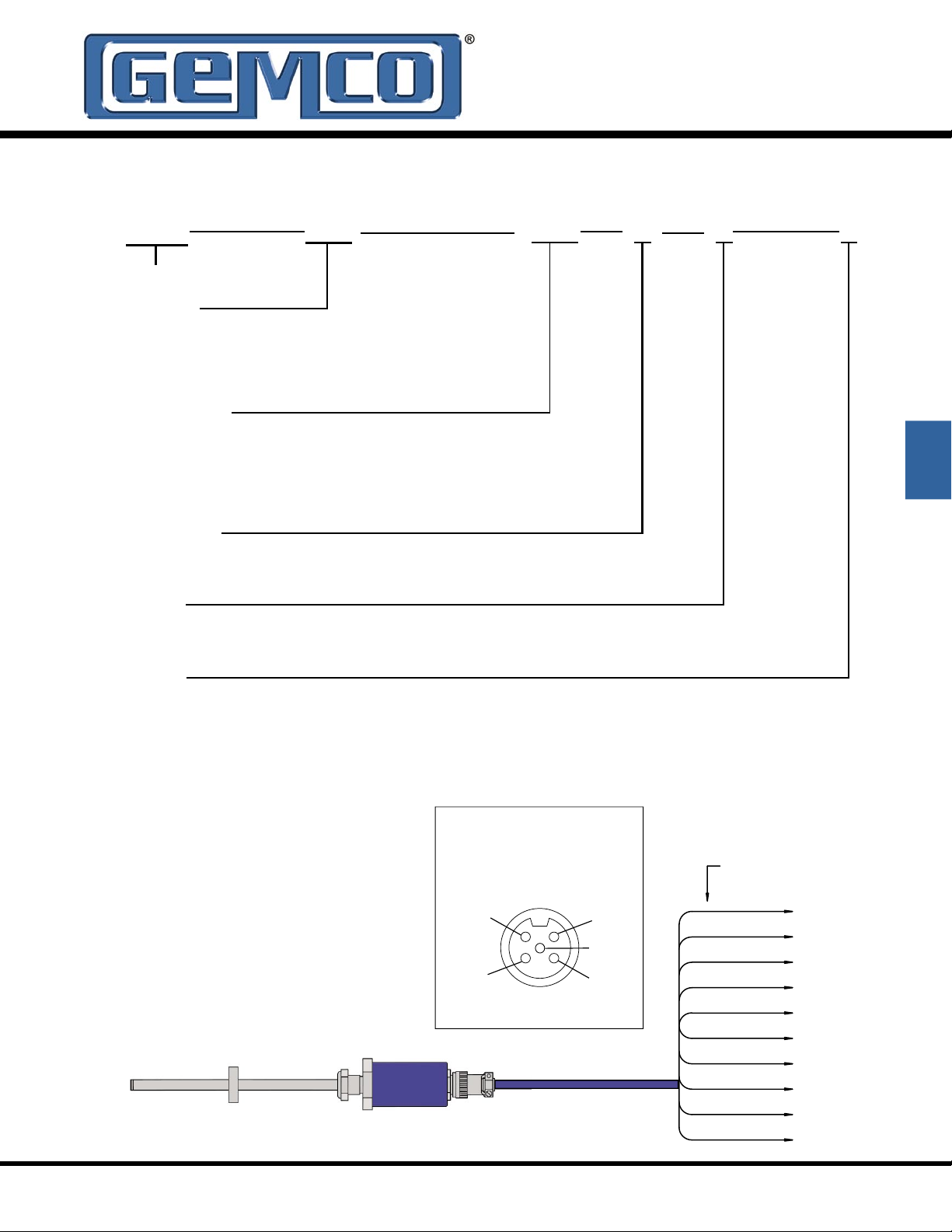
Wiring Diagram
Option “S”
Use Euro Connector (micro 12 mm single
keyway) cordsets, available from most connector
manufacturers or purchased from Ametek.
Program Input
(white wire)
Power Supply Common
(blue wire)
2
3
LDT Connector View
Power 15 to 30 VDC
(brown wire)
1
Position Common
(gray wire)
4
Position
Output
(black wire)
5
Wiring Diagram
Option “E”

952CP BlueOx
BLUE
WHITE
GRAY
PURPLE
BLACK
RED
-INTERROGATION
+GATE
+INTERROGATION
-15 VDC FOR BIPOLAR
POWER SUPPLY
+15 TO +26 VDC
BROWN
-GATE
PIN-OUT FOR STANDARD
CIRCULAR CONNECTOR
AT TRANSDUCER HEAD
GREEN
ORANGE
YELLOW
NO CONNECTION
NO CONNECTION
NO CONNECTION
POWER SUPPLY
COMMON
PIN-C
PIN-B
PIN-J
PIN-K
PIN-A
PIN-F
PIN-E
PIN-D
PIN-G
PIN-H
POWER SUPPLY*
* FOR UNIPOLAR POWER SUPPLY, IT IS RECOMMENDED
TO
CONNECT THIS WIRE TO POWER SUPPLY COMMON
Part Numbering
952CP 0120
X X E
Control Pulse
BlueOx
Stroke in Inches
Insert stroke to 0.1” as a four-place number, enter 12.0”
stroke as 0120; to convert metric strokes, multiply millimeter
value by 0.03937 for inch value
Null Dimension
X = Standard 2 inch Null
952
N_= Insert non-standard Null over 2 inches
(add non-standard portion of Null length to stroke length to calculate list price)
Dead Band
X = Standard Dead Band of 2.5 inches
D_= Insert non-standard Dead Band over 2.5 inches
(add non-standard portion of Dead Band length to stroke length to calculate list price)
Connector
E = Environmental MS connector*
C_= Potted pigtail cable assembly, insert pigtail length in feet
* If option E (environmental connector) is selected, mating
connector and/or pigtail must be ordered separately.
Note 1: On unsupported stroke lengths greater than 4 feet, rod
support bracket(s) and a special magnet should be used.
Note 2: Specify magnet as separate line item (standard
magnet is SD0400800).
Wiring Diagram

952VP BlueOx
BLUE
WHITE
GRAY
PURPLE
BLACK
RED
-INTERROGATION
+GATE
+INTERROGATION
-15 VDC FOR BIPOLAR
POWER SUPPLY
+15 TO +26 VDC
BROWN
-GATE
PIN-OUT FOR STANDARD
CIRCULAR CONNECTOR
AT TRANSDUCER HEAD
GREEN
ORANGE
YELLOW
NO CONNECTION
NO CONNECTION
NO CONNECTION
POWER SUPPLY
COMMON
PIN- C
PIN- B
PIN- J
PIN- K
PIN- A
PIN- F
PIN- E
PIN- D
PIN- G
PIN- H
POWER SUPPLY*
* FOR UNIPOLAR POWER SUPPLY, IT IS RECOMMENDED
TO
CONNECT THIS WIRE TO POWER SUPPLY COMMON
Part Numbering
952VP 0120
X
Variable Pulse
BlueOx
Stroke in Inches
Insert stroke to 0.1” as a four-place number, enter
12.0” stroke as 0120; to convert metric strokes, multiply
millimeter value by 0.03937 for inch value
Null Dimension
X = Standard 2 inch Null
N_= Insert non-standard Null over 2 inches
(add non-standard portion of Null length to stroke length to
calculate list price)
Dead Band
X = Standard Dead Band of 2.5 inches
D_= Insert non-standard Dead Band over 2.5 inches
(add non-standard portion of Dead Band length to
stroke length to calculate list price)
Connector
E = Environmental MS connector*
C_= Potted pigtail cable assembly, insert pigtail length in feet
T = Threaded metal connector (fits MTS - “RB” on Tempo II
M = 1/4 turn quick disconnect (fits MTS - “MS” on Tempo II
X E
TM
or III)
TM
or III)
I
001
952
Interrogation Mode
I = Internal interrogation
E = External interrogation
Recirculations Required
001 (standard) to 127
* If option E (environmental connector) is selected, mating connector and/
or pigtail must be ordered separately.
Note 1: On unsupported stroke lengths greater than 4 feet, rod
support bracket(s) and a special magnet should be used.
Note 2: Specify as magnet separate line item (standard magnet
is SD0400800).
Wiring Diagram

952RS BlueOx
BLUE
WHITE
GRAY
PURPLE
BLACK
RED
-INTERROGATION
+GATE
+INTERROGATION
-15 VDC FOR BIPOLAR
POWER SUPPLY
+15 TO +26 VDC
BROWN
-GATE
PIN-OUT FOR STANDARD
CIRCULAR CONNECTOR
AT TRANSDUCER HEAD
GREEN
ORANGE
YELLOW
NO CONNECTION
NO CONNECTION
NO CONNECTION
POWER SUPPLY
COMMON
PIN-C
PIN-B
PIN-J
PIN-K
PIN-A
PIN-F
PIN-E
PIN-D
PIN-G
PIN-H
POWER SUPPLY*
* FOR UNIPOLAR POWER SUPPLY, IT IS RECOMMENDED
TO
CONNECT THIS WIRE TO POWER SUPPLY COMMON
Part Numbering
952RS
0120
RS422 Start/Stop with
Interrogation Start Sequence
Pulse BlueOx
Stroke in Inches
Insert stroke to 0.1” as a four-place number, enter 12.0” stroke
as 0120; to convert metric strokes, multiply millimeter value by
0.03937 for inch value
Null Dimension
952
X = Standard 2 inch Null
N_= Insert non-standard Null over 2 inches
(add non-standard portion of Null length to stroke length to
calculate list price)
Dead Band
X = Standard Dead Band of 2.5 inches
D_= Insert non-standard Dead Band over 2.5 inches
(add non-standard portion of Dead Band length to stroke
length to calculate list price)
Connector
E = Environmental MS connector*
C_= Potted pigtail cable assembly, insert pigtail length in feet
T = Threaded metal connector (fits MTS - “RB” on Tempo II
M = 1/4 turn quick disconnect (fits MTS - “MS” on Tempo II
TM
TM
or III)
X X
or III)
E
Wiring Diagram
* If option E (environmental connector) is selected, mating
connector and/or pigtail must be ordered separately.
Note1: On unsupported stroke lengths greater than 4 feet, rod
support bracket(s) and a special magnet should be used.
Note 2: Specify magnet as separate line item (standard magnet
is SD0400800).

Magnetostrictive LDT
with Quadrature Output
The BlueOx Quadrature is a magnetostrictive linear
displacement transducer (LDT) for continuous
machine positioning in a variety of industrial
applications. The quadrature output makes it
possible for customers to have a direct interface to
virtually any incremental encoder input or counter
card, eliminating costly absolute encoder converters
and special PLC interface modules.
The BlueOx Quadrature LDT is lab tested and field
proven to stand up to high shock and vibration
without effect. With test results of 2,000 Gs of shock
and 30 Gs of random vibration without false signals
or mechanical damage, the BlueOx Quadrature
LDT is ready to perform in the most demanding
applications.
952QD BlueOx
with Quadrature Output
952
The BlueOx Quadrature LDT can be ordered with
1 to 9999 cycles per inch of output resolution
and the position data is absolute. The transducer
features an input to re-zero the probe “on the fly”.
Another unique feature is the “burst” mode. An
input on the transducer triggers a data transfer
of all the incremental position data relative to the
transducer’s absolute zero position. This can be
used to achieve absolute position updates when
power is restored to the system.
The BlueOx Quadrature is shipped from the factory
pre-calibrated and ready for installation. In addition
to its ability to withstand shock and vibration,
the BlueOx Quadrature is rugged in other ways.
Sensing tube construction is welded stainless
steel, suitable for insertion in 5,000 PSI hydraulic
cylinders.
The electronics are enclosed behind an aluminum
housing with O-ring seals. The BlueOx Quadrature
LDT, with its rugged construction, is at home in
heavy duty areas such as lumber mills, steel mills,
stamping plants and any other harsh environment
where accurate and reliable continuous linear
position sensing is needed.
Input Voltage
Current Draw
Output
Inputs
Resolution
Linearity
Repeatability
Hysteresis
Operating Temperature
Head Electronics
Guide Tube
Operating Pressure
Span Length
Null Zone
Dead Band
Connectors
Update Time
Enclosure
Specifications
13.5 to 26.4 VDC
< 200mA at 15 VDC
Quadrature Output A+, A-, B+, B-, Z+, Z-.
Line Drivers: 5V or Input Power
10 to 30 VDC
0.001”
<.05% (+/- .002” Min)
0.001% of Full Stroke (+/- .002” Min.)
+/-.02% of Full Scale
-40° to 155° F (-40° to 70° C)
-40° to 220° F (-40° to 105° C)
5000 PSI Operational, 10,000 PSI Spike
2” to 168”
2.0”
2.5”
1/4 Turn MS Connector Standard. Potted Pigtail Assembly
Available Optionally
Approx. 1ms for < 60”
Approx. 2ms for > 60” to < 120”
Approx. 3ms > 120”
IP67
Specifications are subject to change without notice.
Specifications are based on a typical 36” LDT .

2.00
DEAD BAND
3/4-16
X 1.00 THRD.
W/ ESNA JAM NUT
CABLE
1.75 DIA.
COVER &
.31
.4O DIA.
TUBE
1.28 DIA.
MAGNET
TUBE BOSS SEAL.
.30 DIA.
NULL
STROKE
2.50
3.00
.38
METAL CIRCULAR
CONNECTOR
2.00
PIGTAIL
VITON O-RING
FOR 1/2" DIA.
HEX
WHITE
BLUE
BROWN
GRAY
RED
BLACK
A+
BURST INPUT
Z-
B-
+15/+26 VDC
POWER SUPPLY
ORANGE
A-
PIN-OUT FOR STANDARD
CIRCULAR CONNECTOR
AT TRANSDUCER HEAD
GREEN
YELLOW
PURPLE
Z+
B+
ZERO INPUT
COMMON
POWER INPUT
PIN- B
PIN- C
PIN- K
PIN- E
PIN- F
PIN- A
PIN- G
PIN- D
PIN- H
PIN- J
952
952QD BlueOx
with Quadrature Output
Dimension Drawing
Wiring Diagram

952QD BlueOx
with Quadrature Output
Part Numbering
952QD
BlueOx with
Quadrature Output
Stroke in Inches
Insert stroke to 0.1” as a four-place
number, enter 12.0” stroke as 0120;
to convert metric strokes, multiply
millimeter value by 0.03937 for inch
value
Null Dimension
X = Standard 2 inch Null
N_= Insert non-standard Null over 2
inches (add non-standard portion of Null
length to stroke length to calculate list price)
Dead Band
X = Standard Dead Band of 2.5 inches
D_= Insert non-standard Dead Band over 2.5 inches
(add non-standard portion of Dead Band length to
stroke length to calculate list price)
Connector
E = Environmental MS connector*
C_= Potted pigtail cable assembly,
insert pigtail length in feet
Output Resolution
Cycles per inch, maximum internal resolution is 0.001 inches
1000 standard (available range is 0001 through 9999)
Input Type
E = Sinking (typically used with sourcing output type)
C = Sourcing (typically used with sinking output type)
T = TTL Level
Quadrature Cycle Output Frequency Range
F1 = 10 KHz F2 = 25 KHz F3 = 50 KHz F4 = 75 KHz
F5 = 100 KHz F6 = 150 KHz F7 = 250 KHz F8 = 500 KHz F9 = 1.00 MHz
Output Mode
M1 = X1 quadrature, consult factory for other output modes
0120
X X
E
1000
E F7 M1
N
D
X
952
Zero Offset Storage
V = Volatile (non retentive)
N = Nonvolatile (retentive, 100,000 storage cycles maximum)
Output Drivers
D = Differential RS422 line driver, TTL compatible
L = Differential line driver 10 to 30 VDC, V out = V in (LDT Power) -1 Volt
Options
X = None
* If option E (environmental connector) is selected,
mating connector and/or pigtail must be ordered separately.
 Loading...