


______________________________________________________________________________________________________________________________
Rev.1
Date 17.06.2013
Page 1 / 14
User’s Manual
Sculptor
Disctrete Pre-Amp with Eq and Peak Limiter
Gem Audio Labs
Tel. : 00 48 508 377 982
office@gemaudiolabs.com
www.gemaudiolabs.com

___________________________________________________________________________________________________________________________
Rev.1
Date 17.06.2013
Page 2 / 14
CE Conformity
We declare with sole responsibility that this product complies with the following norms and
directives:
2006/95/EC LVD (Low Voltage Directive)
2004/108/EC EMC (Electromagnetic Compatibility)
DIN EN 55103-1 EMC of audio equipment- Emission
DIN EN 55103-2 EMC of audio equipment- Immunity
This declaration becomes invalid by any unapproved modification of the device.
Wroclaw, 17.06.2013 B. Radziszewski
SPLASH BARTOSZ RADZISZEWSKI
Wietrzna 36/1
53-024 Wroclaw
POLAND
VAT Reg. Nr : PL8862784446

___________________________________________________________________________________________________________________________
Rev.1
Date 17.06.2013
Page 3 / 14
TABLE OF CONTENTS
INTRODUCTION ................................................................................................................................ 4
FOR SAFE OPERATION ..................................................................................................................... 4
CAUTION .............................................................................................................................................. 5
FOR CORRECT OPERATION ........................................................................................................... 6
THE FRONT PANEL CONTROLS AND THEIR USE .................................................................. 7
THE REAR PANEL ............................................................................................................................. 10
TECHNICAL DATA ........................................................................................................................... 12
ENVIRONMENTAL PROTECTION .............................................................................................. 13
LIMITED WARRANTY ..................................................................................................................... 14

___________________________________________________________________________________________________________________________
Rev.1
Date 17.06.2013
Page 4 / 14
INTRODUCTION
First of all, we would like to thank You sincerely for choosing this GEM AUDIO LABS
Sculptor which combines ease of operation with support for multiple usage environments. As
a company and first of all, as fans of pro audio devices, we do our best in our daily work to
satisfy your most sophisticated sound expectations. We put in your hands the highest quality
product, precisely designed and hand manufactured by our qualified staff, without any
compromise. To build our devices we use only the best, hand-selected electronic
components, we take care about all parameters repeatability and high quality of all our
products.
Please take a little time to read this manual thoroughly, as it will help You to entirely
understand how the Sculptor works and what is important to use it safely.
Gem Audio Labs team.
FOR SAFE OPERATION
INSTALLATION
Before You connect the power cord to the device please check fuses value and make
sure that the voltage switch setting reflects the correct local power line voltage. For
line voltages from 100V to 120V, set the switch to 115V and use 1,25A fuses (slo-blo;
5x20mm). The 230V position is good for all line voltages from 200-240Volts; fuses:
630mA (slo-blo; 5x20mm).
This unit is equipped with a three-pronged AC power cord. To reduce the risk of
electrical shock never remove or otherwise attempt to defeat the ground pin of the
power cord.
Do not allow water to enter this unit or allow the unit to become wet. Fire or electrical
shock may result.
Do not place a container with liquid or small metal objects on top of this unit. Liquid
or metal objects inside this unit are a fire and electrical shock hazard.
Do not place heavy objects, including this unit, on top of the power cord. A damaged
power cord is a fire and electrical shock hazard.

___________________________________________________________________________________________________________________________
Rev.1
Date 17.06.2013
Page 5 / 14
OPERATION
Do not scratch, bend, twist, pull, or heat the power cord. A damaged power cord is a
fire and electrical shock hazard.
Do not remove the unit‟s cover. You could receive an electrical shock. If you think
internal inspection, maintenance, or repair is necessary, contact your dealer or
producer.
Do not modify the unit. Doing so is a fire and electrical shock hazard.
If lightning begins to occur, turn off the power switch of the unit as soon as possible,
and unplug the power plug from the electrical outlet.
If there is a possibility of lightning, do not touch the power plug if it is still connected.
Doing so may be an electrical shock hazard.
Use only the included AC power cord for this unit. Using other types may be a fire
and electrical shock hazard.
IN CASE AN ABNORMALITY OCCURS DURING OPERATION
If the power cord is damaged (i.e., cut or a bare wire is exposed), ask your dealer or
producer for a replacement. Using the unit with a damaged power cord is a fire and
electrical shock hazard.
Should this unit and AC cord be dropped or the cabinet be damaged, turn the power
switch off, remove the power plug from the AC outlet, and contact your dealer or
producer. If you continue using the unit without heeding this instruction, fire or
electrical shock may result.
If you notice any abnormality, such as smoke, odor, or noise, or if a foreign object or
liquid gets inside the unit, turn it off immediately.
Remove the power plug from the AC outlet. Consult your dealer or producer for
repair. Using the unit in this condition is a fire and electrical shock hazard.
CAUTION
INSTALLATION
Keep this unit away from the following locations:
- Locations exposed to oil splashes or steam, such as near cooking stoves, humidifiers,
etc.
- Unstable surfaces, such as a wobbly table or slope.
- Locations exposed to excessive heat, such as inside a car with all the windows closed,
or places that receive direct sunlight.
- Locations subject to excessive humidity or dust accumulation.
Hold the power plug when disconnecting it from an AC outlet. Never pull the cord. A
damaged power cord is a potential fire and electrical shock hazard.
Do not touch the power plug with wet hands. Doing so is a potential electrical shock
hazard.

___________________________________________________________________________________________________________________________
Rev.1
Date 17.06.2013
Page 6 / 14
To relocate the unit, turn the power switch off, remove the power plug from the AC
outlet, and remove all connecting cables. Damaged cables may cause fire or electrical
shock.
OPERATION
Do not cover this unit and use it only in a well-ventilated environment.
If you know you will not use this unit for a log period of time, such as when going on
vacation, remove the power plug from the AC outlet. Leaving it connected is a
potential fire hazard.
FOR CORRECT OPERATION
CONNECTOR PIN ASSIGNMENTS
XLR connectors (INPUT, OUTPUT) are wired according to the AES standard : Pin 1 =
shield, Pin 2 = hot (+), Pin 3= cold (-).
¼” TRS connectors (INSERT SEND, INSERT RETURN) are wired according to the
AES standard: tip = hot (+), ring= cold (-), slave = shield
¼” TS connectors (PEAK LIMIT MASTER, PEAK LIMIT SLAVE) are wired
unbalanced: tip = hot (+), slave = ground
INFLUENCE ON CELL PHONE USAGE
Using a cell phone (mobile telephone) near this unit may induce noise. If noise occurs, use
the telephone away from the unit.
REPLACING ABRASIVE PARTS AND CLEANING THE UNIT
The performance of components with moving contacts, such as toggle switches, rotary
switches and connectors, deteriorates over time. The rate of deterioration depends on the
operating environment and is unavoidable. Consult your dealer or producer about replacing
defective components. Clean this unit only with lint-free damp cloth and do not use cleaning
agents.

___________________________________________________________________________________________________________________________
Rev.1
Date 17.06.2013
Page 7 / 14
THE FRONT PANEL CONTROLS AND THEIR USE
A POWER
POWER on/off switch. The amber light will glow when the unit is powered on. Please turn
down the volume of your studio monitors before turning on or turning off the Sculptor.
B INPUT
An input selector allowing to choose between four signal sources:
DI – For all low level and instrument level signals (1MΩ)
LINE – Line signals (10KΩ)
MIC - Dynamic microphones (600Ω)
MIC 48V – Only for microphones which require phantom power (600Ω)
WARNING! Please ensure to not switch the ‘MIC 48V’ position on when using ribbon
microphones, passive equalizers or any other device which does not accept 48V phantom
power on its output.
C GAIN
15-position audio taper switch:
Mic gain range : -5dB to +65dB in 5dB steps
Line gain range: -25 to +45dB in 5dB steps
D OUTPUT
21-position output fader. This control can be used as a „fine‟ level adjustment or an output
attenuator so that the unit can be run „hot‟ in order to get some distortion without
overloading the next piece of equipment in the chain.
E PHASE
This switch inverts the phase of the signal.

___________________________________________________________________________________________________________________________
Rev.1
Date 17.06.2013
Page 8 / 14
F DI
Direct HI-Z input for all low level and instrument level signals.
G LIMIT
The Peak Limit hard bypass switch.
H EQ
The Eq hard bypass switch.
I HI CUT
6-position active LPF (12dB/oct). EQ points are 4.7KHz, 7.5KHz, 9.1KHz, 12KHz, 16KHz,
20KHz.
J LO CUT
6-position active HPF (12dB/oct). EQ points are 20Hz, 40Hz, 60Hz, 90Hz, 150Hz, 300Hz.
K LO BOOST [Hz]
7-position inductor based low frequencies boost. Both peaking and shelving characters are
available. EQ points are 30Hz, 50Hz, 70Hz, 100Hz, 200Hz (peak), 100Hz, 200Hz (shelf). The
Q of the peak sharpens the more you boost.
L LO BOOST [dB]
11-position low frequencies gain switch. dB points are 0dB ,+1dB, +2dB, +4dB, +6dB, +8dB,
+10dB, +12dB, +14dB, +16dB, +18dB.
M MID CUT [Hz]
6-position active mid cut (bell-shaped) filter. EQ points are 200Hz, 250Hz, 350Hz, 500Hz,
600Hz, 850Hz.
N MID CUT [Q]
Mid cut sharp or wide Q characteristic switch.
O MID CUT [dB]
11-position mid cut gain switch. dB points are 0dB, -1dB, -2dB, -3dB, -4dB, -5dB, -6dB, -8dB,
-10dB, -12dB, -15dB.

___________________________________________________________________________________________________________________________
Rev.1
Date 17.06.2013
Page 9 / 14
P MID PEAK [Hz]
6-position active mid peak (bell-shaped) filter. EQ points are 1.2KHz, 1.8KHz, 2.2KHz,
3.9KHz, 5.8KHz, 8.1KHz.
R MID PEAK [Q]
Mid peak sharp or wide Q characteristic switch.
S MID PEAK [dB]
11-position mid peak gain switch. dB points are 0dB, +1dB, +2dB, +3dB, +4dB, +5dB, +6dB,
+8dB, +10dB, +12dB, +15dB.
T HI SHELF [Hz]
6-position capacitor based high boost (shelving characteristic). EQ points are 6.8KHz,
8.1KHz, 12KHz, 16KHz, 20KHz, 27KHz.
U HI SHELF [dB]
11-position hi shelf gain switch. dB points are 0dB ,+1dB, +2dB, +3dB, +4dB, +6dB, +8dB,
+10dB, +12dB, +14dB, +16dB.
W PEAK LIMIT HARD/SOFT
The Peak Limit mode switch allows to choose between two unique limit modes : Hard
(OA202 Vintage Silicon diodes) and Soft (EAA91/6AL5 Vacuum Tube double diode).
The limiter is very specific. It is unique analog brickwall solution based on metal-oxide
semiconductor field effect transistors (MOSFET).
Y PEAK REDUCTION METER
10-led meter which is a practical peak reduction indication. dB steps are 0.5 , 1 , 1.5 , 2 , 2.5 , 3,
4 , 5 , 6 , >7 dB.
Z PEAK LIMIT THRESHOLD
Variable peak limiter threshold working in a range between +10 and +20dBu. Two (or more
units) can be linked via the Master/Slave jacks on the rear panel.
___________________________________________________________________________________________________________________________
Rev.1
Date 17.06.2013
Page 10 / 14
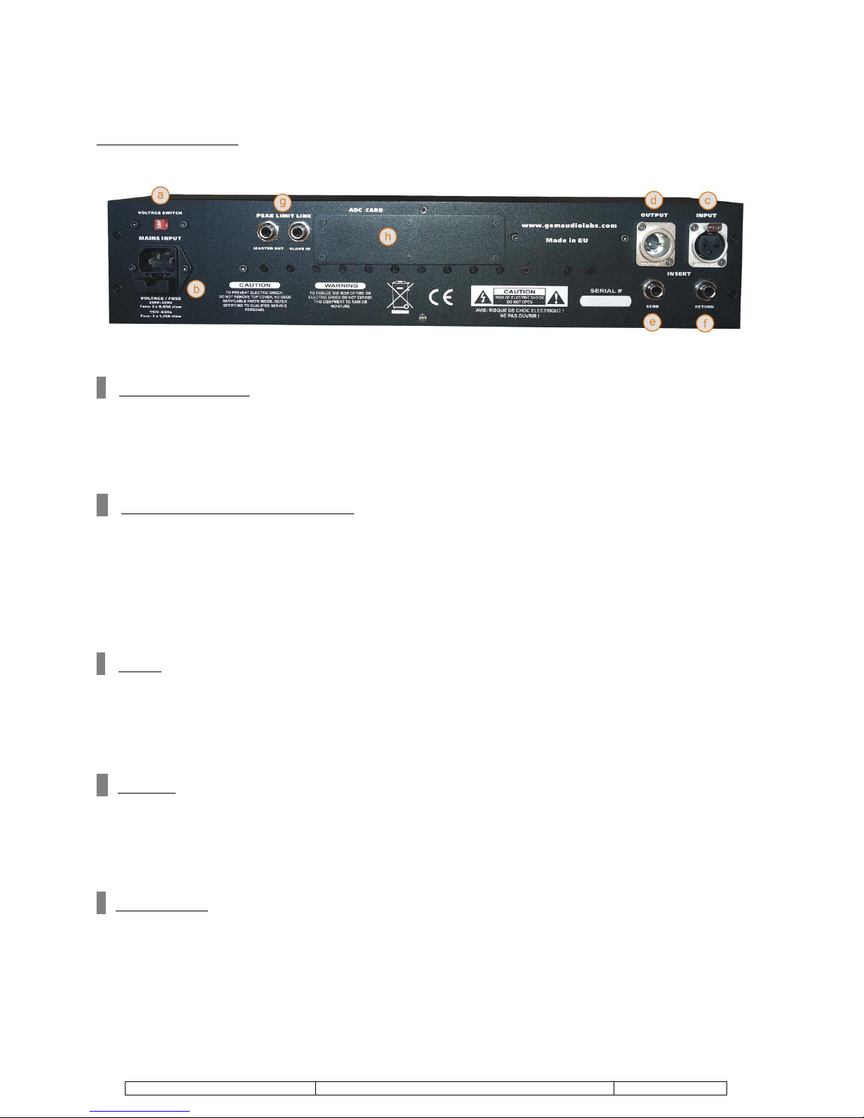
THE REAR PANEL
a VOLTAGE SWITCH
Make sure that the voltage switch setting reflects the correct local power line voltage. For line
voltages from 100V to 120V, set the switch to 115V. The 230V position is good for all line
voltages from 200-240Volts.
b MAINS INPUT / AC FUSES HOLDER
The mains AC connector is a standard IEC-type 3 pin connector with a AC fuses (2 pieces)
holder. The ground of this AC connector is permanently internally connected to the chassis of
the Sculptor for safety. It is important to change the fuse before changing the supply voltage:
630mA (slo-blo; 5x20mm) for 230V~50 Hz
1,25A (slo-blo; 5x20mm) for 115V~60 Hz
c INPUT
Balanced input XLR wired according to the AES standard : Pin 1 = shield, Pin 2 = hot (+), Pin
3= cold (-). In order to avoid hum, it is recommended to use the device only in balanced
connections.
d OUTPUT
Balanced output XLR wired according to the AES standard : Pin 1 = shield, Pin 2 = hot (+),
Pin 3= cold (-). In order to avoid hum, it is recommended to use the device only in balanced
connections.
e INSERT SEND
Balanced insert TRS ¼” send wired according to the AES standard : Slave = shield, Tip = hot
(+), Ring = cold (-). In order to avoid hum, it is recommended to use the device only in
balanced connections.

___________________________________________________________________________________________________________________________
Rev.1
Date 17.06.2013
Page 11 / 14
f INSERT RETURN
Balanced insert TRS ¼” return wired according to the AES standard : Slave = shield, Tip =
hot (+), Ring = cold (-). In order to avoid hum, it is recommended to use the device only in
balanced connections.
g PEAK LIMIT LINK
Use this jacks to connect two Sculptors working as a stereo couple. Use unbalanced jack cable
( Slave = shield, Tip = hot (+) )and connect it from one “master” unit MASTER OUT to
second “slave” unit SLAVE IN. Then the “master” unit controls thresholds in the both units.
h ADC
An extension for optional Analog to Digital Converter Card. Sold separately.

____________________________________________________________________________________________________________________________
Rev.1
Date 17.06.2013
Page 12 / 14
TECHNICAL DATA
MIC/LINE Input: Transformer balanced XLR (Carnhill UK)
DIRECT Input: Un-balanced TS ¼”
Output: Transformer balanced XLR (Carnhill UK)
Input impedance: Mic 600 Ω , Line 10KΩ, Direct 1MΩ
Output impedance: 600Ω
Insert: Balanced TRS ¼” (separated SEND and RETURN)
Mic gain (stepped) : -5 to +65dB
Line gain (stepped): -25 to +45dB
Output gain (stepped): Acting as a console fader trimming input signals
Phase switch
Phantom power
HPF (stepped): 20Hz, 40Hz, 60Hz, 90Hz, 150Hz, 300Hz (12dB/oct) – Active filters
LPF (stepped): 4.7KHz, 7.5KHz, 9.1KHz, 12KHz, 16KHz, 20KHz (12dB/oct)- Active
filters
Lo boost freq (stepped): 30Hz, 50Hz, 70Hz, 100Hz, 200Hz, 100Hz (shelf), 200Hz (shelf)-
Carnhill Inductor-based stepped passive filters
Lo boost gain (stepped): 0dB ,+1dB, +2dB, +4dB, +6dB, +8dB, +10dB, +12dB, +14dB,
+16dB, +18dB
Mid cut freq (stepped): 200Hz, 250Hz, 350Hz, 500Hz, 600Hz, 850Hz - Active filters
Mid cut gain (stepped): 0dB, -1dB, -2dB, -3dB, -4dB, -5dB, -6dB, -8dB, -10dB, -12dB,
-15dB
Mid cut Q switch: sharp, wide
Mid peak freq (stepped): 1.2KHz, 1.8KHz, 2.2KHz, 3.9KHz, 5.8KHz, 8.1KHz – Active
filters
Mid peak gain (stepped): 0dB, +1dB, +2dB, +3dB, +4dB, +5dB, +6dB, +8dB, +10dB,
+12dB, +15dB
Mid peak Q switch: sharp, wide
High shelf freq (stepped): 6.8KHz, 8.1KHz, 12KHz, 16KHz, 20KHz, 27KHz –
Capacitors- based passive filters
High shelf gain (stepped): 0dB ,+1dB, +2dB, +3dB, +4dB, +6dB, +8dB, +10dB, +12dB,
+14dB, +16dB
Peak Limiter: Analog brick wall limiter working in a range between +10 and +20dBu.
Two unique limit modes : Hard (Silicon) and Soft (Vacuum tube). Limit threshold is
variable (Two units can be linked on the rear panel for stereo operation)
Peak Reduction Meter : 0.5 , 1 , 1.5 , 2 , 2.5 , 3 , 4 , 5 , 6 , >7 dB
PSU: internal
Fuses type: 230V : 630mA (slo-blo; 5x20mm) /115V : 1,25A (slo-blo; 5x20mm)
Power consumption: 85W
Dimensions (WxHxD) : 483x88mm (2U) x 245mm
Weight: 5,8 kg

____________________________________________________________________________________________________________________________
Rev.1
Date 17.06.2013
Page 13 / 14
ENVIRONMENTAL PROTECTION
At the end of its operating life, this product must not be disposed of with regular household
waste but must be returned to a collection point for the recycling of electrical and electronic
equipment. The wheelie bin symbol on the product and user„s manual indicates that. The
materials can be re-used in accordance with their markings. Through re-use, recycling of raw
materials, or other forms of recycling of old products, you are making an important
contribution to the protection of our environment. Your local administrative office can advise
you of the responsible waste disposal point.
Our devices are packaged in environmentally friendly packaging that can be reprocessed.
Remember about waste segregation.

____________________________________________________________________________________________________________________________
Rev.1
Date 17.06.2013
Page 14 / 14
LIMITED WARRANTY
Should you need to use our warranty service on this product, we refer you to the terms and conditions stipulated
below.
This warranty is valid for one year from the date of purchase by the consumer and is not transferable.
SPLASH BARTOSZ RADZISZEWSKI, Wietrzna 36/1, 53-024 Wroclaw, POLAND (called the PRODUCER
hereafter) selling products under Gem Audio Labs trade mark will only give warranty on products
purchased through authorized dealers or directly from the producer.
PLEASE RETAIN YOUR SALES RECEIPT. IT IS YOUR PROOF OF PURCHASE COVERING YOUR
LIMITED WARRANTY. THIS LIMITED WARRANTY IS VOID WITHOUT SUCH PROOF OF PURCHASE.
This limited warranty does not cover the product if it has been electronically or mechanically modified in any
way.
This limited warranty is invalid if the factory-applied serial number has been altered or removed from the
product.
Natural wear is not covered by this warranty.
Damage/defects caused by the following conditions are not covered by this limited warranty: improper
handling, neglect or failure to operate the unit in compliance with the instructions given by the PRODUCER‟s
user manual; connection or operation of the unit in any way that does not comply with the technical or safety
regulations applicable in the country where the product is used; damage/defects caused by acts of
God/Nature (accident, fire, flood, etc.) or any other condition that is beyond the control of the PRODUCER.
Warranty will not apply because of incorrect storage, dropping, excessive shocks, corrosions, dirt, water or
sand damages.
To confirm your warranty please register your Gem Audio Labs product shortly after purchase. Please fill out
your user registration card (included in the original packaging) and send it via e-mail to
office@gemaudiolabs.com or via mail to: SPLASH BARTOSZ RADZISZEWSKI, Wietrzna 36/1, 53-024
Poland.
All returns must be in the original packaging, accompanied by the return authorization. Please fill out your
return authorization form (included in the original packaging) and send it to your local distributor from
whom You purchased the unit. If the unit has been purchased directly from producer, please send the return
authorization form via e-mail to office@gemaudiolabs.com or via mail to: SPLASH BARTOSZ
RADZISZEWSKI, Wietrzna 36/1, 53-024 Poland.
All returns must be shipped via insured freight at the customer's own expense.
In case when a product must be returned to the factory from a country outside Poland, the customer shall
adhere to specific shipping, customs, and commercial invoicing Instructions given with the return
authorization as the PRODUCER will not be responsible for transportation costs or customs fees related to
any importation or re-exportation charges whatsoever.
After repair, a product will be returned to the customer via prepaid, insured freight, method and carrier to be
determined by the PRODUCER
All damages caused by transport are not covered by this warranty.
Contact data
For the warranty confirmation, technical support and return authorizations, please contact:
SPLASH BARTOSZ RADZISZEWSKI
Wietrzna 36/1
53-024 Wroclaw
Poland
office@gemaudiolabs.com
 Loading...