

Page 1
Solar 7000
Patient Monitor
Solar 7000/8000/SolarView
Patient Monitor
Field Service Manual
414993-001 Revision H
Page 2

NOTE: Due to continuing product innovation, specifications in this
manual are subject to change without notice.
Trademarks
Trademarked names appear throughout this document. Rather than list
the names and entities that own the trademarks or insert a trademark
symbol with each mention of the trademarked name, the publisher states
that it is using the names only for editorial purposes and to the benefit of
the trademark owner with no intention of improperly using that
trademark.
900 SC, ACCUSKETCH, AccuVision, APEX, AQUA-KNOT, ARCHIVIST, Autoseq, BABY
MAC, C Qwik Connect, CardioServ, CardioSmart, CardioSys, CardioWindow, CASE, CD
TELEMETRY, CENTRA, CHART GUARD, CINE 35, CORO, COROLAN,
COROMETRICS, Corometrics Sensor Tip, CRG PLUS, DASH, Digistore, Digital DATAQ,
E for M, EAGLE, Event-Link, FMS 101B, FMS 111, HELLIGE, IMAGE STORE,
INTELLIMOTION, IQA, LASER SXP, MAC, MAC-LAB, MACTRODE, MANAGED USE,
MARQUETTE, MARQUETTE MAC, MARQUETTE MEDICAL SYSTEMS, MARQUETTE
UNITY NETWORK, MARS, MAX, MEDITEL, ME I, MEI in the circle logo, MEMOPORT,
MEMOPORT C, MINISTORE, MINNOWS, Monarch 8000, MULTI-LINK,
MULTISCRIPTOR, MUSE, MUSE CV, Neo-Trak, NEUROSCRIPT, OnlineABG,
OXYMONITOR, Pres-R-Cuff, PRESSURE-SCRIBE, QMI, QS, Quantitative Medicine,
Quantitative Sentinel, RAC RAMS, RSVP, SAM, SEER, SILVERTRACE, SOLAR,
SOLARVIEW, Spectra 400, Spectra-Overview, Spectra-Tel, ST GUARD, TRAM, TRAMNET, TRAM-RAC, TRAMSCOPE, TRIM KNOB, Trimline, UNION STATION, UNITY logo,
UNITY NETWORK, Vari-X, Vari-X Cardiomatic, VariCath, VARIDEX, VAS, and Vision
Care Filter are trademarks of GE Marquette Medical Systems, Inc. registered in the United
States Patent and Trademark Office.
12SL, 15SL, Access, AccuSpeak, ADVANTAGE, BAM, BODYTRODE, Cardiomatic,
CardioSpeak, CD TELEMETRY
Event-Link Cirrus, Event-Link Cumulus, Event-Link Nimbus, HI-RES, ICMMS, IMAGE
VAULT, IMPACT.wf, INT ER-LEAD, IQA, LIFEWATCH, Manag ed Use, MARQUETTE
PRISM, MARQUETTE
CardioWindow, NST PRO, NAUTILUS, O
Prism, QUIK CONNECT V, QUICK CONNECT, QT Guard, SMART-PAC, SMARTLOOK,
Spiral Lok, Sweetheart, UNITY, Universal, Waterfall, and Walkmom are trademarks of GE
Marquette Medical Systems, Inc.
®
®
-LAN, CENTRALSCOPE, Corolation, EDIC, EK-Pro,
RESPONDER, MENTOR, MicroSmart, MMS, MRT, MUSE
SENSOR, Octanet, OMRS, PHi-Res, Premium,
2
GE Marquette Medical Systems, Inc.
8200 W. Tower Ave.
Milwaukee, WI 53223 USA
Tel: 414.355.5000
800.558.5120 (USA only)
Fax: 414.355.3790
Marquette Hellige GmbH
Postfach 60 02 65
D-79032 Freiburg
Germany
Tel: 49.761.45.43.0
Fax: 49.761.45.43.233
© GE Marquette Medical Systems, Inc., 2000. All rights reserved.
T-2 Solar 7000/8000/View Patient Monitor Revision H
414993-001 13 January 2000
Page 3

CONTENTS
1 INTRODUCTION . . . . . . . . . . . . . . . . . . . . . . . . . . . . . . . . . . . . . . . . . . . . 1-1
Manual Information . . . . . . . . . . . . . . . . . . . . . . . . . . . . . . . . . . . . . . . . . .1-2
Revision History . . . . . . . . . . . . . . . . . . . . . . . . . . . . . . . . . . . . . . . . .1-2
Manual Purpose . . . . . . . . . . . . . . . . . . . . . . . . . . . . . . . . . . . . . . . . . 1-2
Intended Audience . . . . . . . . . . . . . . . . . . . . . . . . . . . . . . . . . . . . . . .1-2
Safety Information . . . . . . . . . . . . . . . . . . . . . . . . . . . . . . . . . . . . . . . . . . .1-3
Responsibility of the Manufacturer . . . . . . . . . . . . . . . . . . . . . . . . . . . 1-3
Intended Use . . . . . . . . . . . . . . . . . . . . . . . . . . . . . . . . . . . . . . . . . . . 1-3
Equipment Symbols . . . . . . . . . . . . . . . . . . . . . . . . . . . . . . . . . . . . . .1-4
Warnings, Cautions, and Notes . . . . . . . . . . . . . . . . . . . . . . . . . . . . . 1-5
Service Information . . . . . . . . . . . . . . . . . . . . . . . . . . . . . . . . . . . . . . . . . . 1-6
Service Requirements . . . . . . . . . . . . . . . . . . . . . . . . . . . . . . . . . . . . 1-6
Equipment Identification . . . . . . . . . . . . . . . . . . . . . . . . . . . . . . . . . . . 1-6
Warranty . . . . . . . . . . . . . . . . . . . . . . . . . . . . . . . . . . . . . . . . . . . . . . . 1-6
2 EQUIPMENT OVERVIEW . . . . . . . . . . . . . . . . . . . . . . . . . . . . . . . . . . . . .2-1
System Components . . . . . . . . . . . . . . . . . . . . . . . . . . . . . . . . . . . . . . . .2-2
What is a Solar 7000/8000 Patient Monitoring System? . . . . . . . . . .2-2
What is the Marquette Unity Network? . . . . . . . . . . . . . . . . . . . . . . . .2-3
What is a Solar 7000 Patient Monitor? . . . . . . . . . . . . . . . . . . . . . . . . 2-4
What is a Solar 8000 Patient Monitor? . . . . . . . . . . . . . . . . . . . . . . . . 2-5
What is a SolarView Remote Display Controller? . . . . . . . . . . . . . . .2-6
What is a Tram-rac Housing? . . . . . . . . . . . . . . . . . . . . . . . . . . . . . . . 2-6
What is a DDW? . . . . . . . . . . . . . . . . . . . . . . . . . . . . . . . . . . . . . . . . . 2-7
What is a PRN 50 Digital Writer? . . . . . . . . . . . . . . . . . . . . . . . . . . . . 2-7
What is a Remote Control? . . . . . . . . . . . . . . . . . . . . . . . . . . . . . . . .2-8
What is a Remote Display? . . . . . . . . . . . . . . . . . . . . . . . . . . . . . . . .2-8
What is a Tram-net Hub Assembly? . . . . . . . . . . . . . . . . . . . . . . . . . . 2-9
What is a Tram-net Interface? . . . . . . . . . . . . . . . . . . . . . . . . . . . . .2-10
What is an Octanet Connectivity Device? . . . . . . . . . . . . . . . . . . . .2-10
What is a TMSS? . . . . . . . . . . . . . . . . . . . . . . . . . . . . . . . . . . . . . . . 2-11
Technical Specifications . . . . . . . . . . . . . . . . . . . . . . . . . . . . . . . . . . . . . 2-12
Preparation for Use . . . . . . . . . . . . . . . . . . . . . . . . . . . . . . . . . . . . . . . . . 2-17
Power Connection . . . . . . . . . . . . . . . . . . . . . . . . . . . . . . . . . . . . . . 2-17
Tram-rac Housing Connection . . . . . . . . . . . . . . . . . . . . . . . . . . . . .2-18
Marquette Unity Network Connection . . . . . . . . . . . . . . . . . . . . . . . . 2-18
Interconnection . . . . . . . . . . . . . . . . . . . . . . . . . . . . . . . . . . . . . . . . .2-19
Tram-rac 4A Housing . . . . . . . . . . . . . . . . . . . . . . . . . . . . . . . . . 2-20
Tram-rac 2 Housing . . . . . . . . . . . . . . . . . . . . . . . . . . . . . . . . . . 2-21
Dual Tram-rac Housings . . . . . . . . . . . . . . . . . . . . . . . . . . . . . .2-22
Octanet . . . . . . . . . . . . . . . . . . . . . . . . . . . . . . . . . . . . . . . . . . . 2-24
DDW . . . . . . . . . . . . . . . . . . . . . . . . . . . . . . . . . . . . . . . . . . . . . 2-24
PRN 50 . . . . . . . . . . . . . . . . . . . . . . . . . . . . . . . . . . . . . . . . . . . 2-25
Local/Remote Displays . . . . . . . . . . . . . . . . . . . . . . . . . . . . . . . 2-27
Cabling Schemes . . . . . . . . . . . . . . . . . . . . . . . . . . . . . . . . . . . . 2-31
Remote Control . . . . . . . . . . . . . . . . . . . . . . . . . . . . . . . . . . . . . 2-34
Revision H Solar 7000/8000/View Patient Monitor i
414993-001
Page 4

CONTENTS
Tram-net Interface Adapter . . . . . . . . . . . . . . . . . . . . . . . . . . . . 2-35
Octanet Connectivity Device . . . . . . . . . . . . . . . . . . . . . . . . . . . 2-36
TMSS . . . . . . . . . . . . . . . . . . . . . . . . . . . . . . . . . . . . . . . . . . . . . 2-37
Power Up . . . . . . . . . . . . . . . . . . . . . . . . . . . . . . . . . . . . . . . . . . . . . . . .2-38
For all Solar Monitors . . . . . . . . . . . . . . . . . . . . . . . . . . . . . . . . . . . .2-38
For Monochrome Solar 8000 . . . . . . . . . . . . . . . . . . . . . . . . . . . . . .2-38
Configuration . . . . . . . . . . . . . . . . . . . . . . . . . . . . . . . . . . . . . . . . . . 2-38
More About Tram-net Communication . . . . . . . . . . . . . . . . . . . . . . . . . .2-39
Internal Hub . . . . . . . . . . . . . . . . . . . . . . . . . . . . . . . . . . . . . . . . . . .2-39
Tram-net Hub Assembly . . . . . . . . . . . . . . . . . . . . . . . . . . . . . . . . . . 2-40
More About Ethernet Communication . . . . . . . . . . . . . . . . . . . . . . . . . . .2-41
Twisted Pair . . . . . . . . . . . . . . . . . . . . . . . . . . . . . . . . . . . . . . . . . . . 2-41
Concentrator . . . . . . . . . . . . . . . . . . . . . . . . . . . . . . . . . . . . . . . . . . . 2-42
Thin-net /Thick-net . . . . . . . . . . . . . . . . . . . . . . . . . . . . . . . . . . . . . . 2-42
Node . . . . . . . . . . . . . . . . . . . . . . . . . . . . . . . . . . . . . . . . . . . . . . . . .2-42
Segment and Branch . . . . . . . . . . . . . . . . . . . . . . . . . . . . . . . . . . . . 2-42
Repeater . . . . . . . . . . . . . . . . . . . . . . . . . . . . . . . . . . . . . . . . . . . . . . 2-43
Bridge . . . . . . . . . . . . . . . . . . . . . . . . . . . . . . . . . . . . . . . . . . . . . . . .2-43
What is Twisted Pair Cabling (10 Base-T)? . . . . . . . . . . . . . . . . . . . 2-44
3 MAINTENANCE . . . . . . . . . . . . . . . . . . . . . . . . . . . . . . . . . . . . . . . . . . . . . 3-1
Maintenance Schedule . . . . . . . . . . . . . . . . . . . . . . . . . . . . . . . . . . . . . . .3-2
Manufacturer Recommendations . . . . . . . . . . . . . . . . . . . . . . . . . . . .3-2
Manufacturer Responsibility . . . . . . . . . . . . . . . . . . . . . . . . . . . . . . . .3-2
Visual Inspection . . . . . . . . . . . . . . . . . . . . . . . . . . . . . . . . . . . . . . . . . . . .3-3
Cleaning . . . . . . . . . . . . . . . . . . . . . . . . . . . . . . . . . . . . . . . . . . . . . . . . . .3-4
Cleaning Precautions . . . . . . . . . . . . . . . . . . . . . . . . . . . . . . . . . . . . . 3-4
Cleaning the Display . . . . . . . . . . . . . . . . . . . . . . . . . . . . . . . . . . . . .3-4
Exterior Cleaning . . . . . . . . . . . . . . . . . . . . . . . . . . . . . . . . . . . . . . . . 3-4
Cleaning Inside the Solar 7000 Color Monitor . . . . . . . . . . . . . . . . . .3-5
Electrical Safety Tests . . . . . . . . . . . . . . . . . . . . . . . . . . . . . . . . . . . . . . . 3-6
General . . . . . . . . . . . . . . . . . . . . . . . . . . . . . . . . . . . . . . . . . . . . . . . . 3-6
Recommendations . . . . . . . . . . . . . . . . . . . . . . . . . . . . . . . . . . . . . . . 3-6
Test Conditions . . . . . . . . . . . . . . . . . . . . . . . . . . . . . . . . . . . . . .3-6
Test Equipment . . . . . . . . . . . . . . . . . . . . . . . . . . . . . . . . . . . . . .3-6
Wall Receptacle Test . . . . . . . . . . . . . . . . . . . . . . . . . . . . . . . . . . . . .3-7
Ground (Earth) Integrity . . . . . . . . . . . . . . . . . . . . . . . . . . . . . . . . . . . 3-7
Ground Continuity Test . . . . . . . . . . . . . . . . . . . . . . . . . . . . . . . .3-7
Impedance of Protective Earth Connection . . . . . . . . . . . . . . . . . 3-7
Ground (Earth) Wire Leakage Current Tests . . . . . . . . . . . . . . . . . . . 3-9
Enclosure Leakage Current Test . . . . . . . . . . . . . . . . . . . . . . . . . . .3-11
Patient (Source) Leakage Current Test . . . . . . . . . . . . . . . . . . . . . .3-13
Patient (Sink) Leakage Current Test
(Mains Voltage on the Applied Part) . . . . . . . . . . . . . . . . . . . . . . . 3-15
Test Completion . . . . . . . . . . . . . . . . . . . . . . . . . . . . . . . . . . . . . . . .3-16
Checkout Procedure . . . . . . . . . . . . . . . . . . . . . . . . . . . . . . . . . . . . . . . .3-17
General . . . . . . . . . . . . . . . . . . . . . . . . . . . . . . . . . . . . . . . . . . . . . . . 3-17
Required Tools/Special Equipment . . . . . . . . . . . . . . . . . . . . . .3-17
Procedure . . . . . . . . . . . . . . . . . . . . . . . . . . . . . . . . . . . . . . . . . . . . .3-17
ii Solar 7000/8000/View Patient Monitor Revision H
414993-001
Page 5

CONTENTS
General Monitor Check . . . . . . . . . . . . . . . . . . . . . . . . . . . . . . .3-17
Solar 7000 Display Check . . . . . . . . . . . . . . . . . . . . . . . . . . . . .3-18
Solar 8000/View Display Check . . . . . . . . . . . . . . . . . . . . . . . . .3-19
Tram-rac Housing Check . . . . . . . . . . . . . . . . . . . . . . . . . . . . . .3-19
Tram-net Communication Check . . . . . . . . . . . . . . . . . . . . . . . . 3-21
LAN Network Check . . . . . . . . . . . . . . . . . . . . . . . . . . . . . . . . .3-21
Remote Control Check . . . . . . . . . . . . . . . . . . . . . . . . . . . . . . .3-21
Video/Alarm Check . . . . . . . . . . . . . . . . . . . . . . . . . . . . . . . . . . 3-21
Tram-net Interface Check . . . . . . . . . . . . . . . . . . . . . . . . . . . . . 3-21
Octanet Check . . . . . . . . . . . . . . . . . . . . . . . . . . . . . . . . . . . . . . 3-21
Completion . . . . . . . . . . . . . . . . . . . . . . . . . . . . . . . . . . . . . . . . . . . .3-21
PM Form . . . . . . . . . . . . . . . . . . . . . . . . . . . . . . . . . . . . . . . . . . . . . . 3-22
Repair Log . . . . . . . . . . . . . . . . . . . . . . . . . . . . . . . . . . . . . . . . . . . . . . . 3-23
4 TROUBLESHOOTING . . . . . . . . . . . . . . . . . . . . . . . . . . . . . . . . . . . . . . . . 4-1
Introduction . . . . . . . . . . . . . . . . . . . . . . . . . . . . . . . . . . . . . . . . . . . . . . . .4-3
Troubleshooting Outline . . . . . . . . . . . . . . . . . . . . . . . . . . . . . . . . . . . 4-3
Terms Used . . . . . . . . . . . . . . . . . . . . . . . . . . . . . . . . . . . . . . . . . . . .4-4
Abort . . . . . . . . . . . . . . . . . . . . . . . . . . . . . . . . . . . . . . . . . . . . . . 4-4
Boot Loader . . . . . . . . . . . . . . . . . . . . . . . . . . . . . . . . . . . . . . . . . 4-4
Cold Start . . . . . . . . . . . . . . . . . . . . . . . . . . . . . . . . . . . . . . . . . . . 4-4
Configured Memory . . . . . . . . . . . . . . . . . . . . . . . . . . . . . . . . . . . 4-4
Continue . . . . . . . . . . . . . . . . . . . . . . . . . . . . . . . . . . . . . . . . . . .4-4
Display On/Off . . . . . . . . . . . . . . . . . . . . . . . . . . . . . . . . . . . . . . .4-4
Protected Memory . . . . . . . . . . . . . . . . . . . . . . . . . . . . . . . . . . . .4-4
Power Cycle . . . . . . . . . . . . . . . . . . . . . . . . . . . . . . . . . . . . . . . . .4-5
Service Mode/Menu . . . . . . . . . . . . . . . . . . . . . . . . . . . . . . . . . . .4-5
Warm Start . . . . . . . . . . . . . . . . . . . . . . . . . . . . . . . . . . . . . . . . . .4-5
Block Theory Diagrams . . . . . . . . . . . . . . . . . . . . . . . . . . . . . . . . . . . . . . 4-6
Solar 7000 Color Monitor . . . . . . . . . . . . . . . . . . . . . . . . . . . . . . . . . . 4-6
Solar 7000 Monochrome Monitor . . . . . . . . . . . . . . . . . . . . . . . . . . . .4-7
Solar 8000 Processing Unit . . . . . . . . . . . . . . . . . . . . . . . . . . . . . . . . 4-8
SolarView Remote Display Controller . . . . . . . . . . . . . . . . . . . . . . . . 4-9
Block Theory of Operation . . . . . . . . . . . . . . . . . . . . . . . . . . . . . . . . . . .4-10
Overview . . . . . . . . . . . . . . . . . . . . . . . . . . . . . . . . . . . . . . . . . . . . . 4-10
Main Processor PCB . . . . . . . . . . . . . . . . . . . . . . . . . . . . . . . . . . . . 4-10
Display Processing Circuitry . . . . . . . . . . . . . . . . . . . . . . . . . . . 4-10
Remote/Local Display Circuitry . . . . . . . . . . . . . . . . . . . . . . . . . 4-10
Remote Alarm Circuitry . . . . . . . . . . . . . . . . . . . . . . . . . . . . . . . 4-10
Communication Circuitry . . . . . . . . . . . . . . . . . . . . . . . . . . . . . .4-11
Low-Voltage Power Supply . . . . . . . . . . . . . . . . . . . . . . . . . . . . . . .4-11
Keycap PCB . . . . . . . . . . . . . . . . . . . . . . . . . . . . . . . . . . . . . . . . . . . 4-11
Additional Solar 7000 Circuit Boards . . . . . . . . . . . . . . . . . . . . . . . . 4-11
Mono CRT Controller PCB . . . . . . . . . . . . . . . . . . . . . . . . . . . .4-11
Color CRT Controller PCB . . . . . . . . . . . . . . . . . . . . . . . . . . . . . 4-11
Deflection PCB (Color Only) . . . . . . . . . . . . . . . . . . . . . . . . . . . 4-11
Block Diagram of Internal Cabling . . . . . . . . . . . . . . . . . . . . . . . . . . . . . 4-12
Solar 7000 Color Monitor . . . . . . . . . . . . . . . . . . . . . . . . . . . . . . . . . 4-12
Solar 7000 Monochrome Monitor . . . . . . . . . . . . . . . . . . . . . . . . . . .4-16
Solar 8000/View Processing Unit . . . . . . . . . . . . . . . . . . . . . . . . . . . 4-20
Communication Connectors . . . . . . . . . . . . . . . . . . . . . . . . . . . . . . . . . . 4-22
Revision H Solar 7000/8000/View Patient Monitor iii
414993-001
Page 6

CONTENTS
Async COMM Signals . . . . . . . . . . . . . . . . . . . . . . . . . . . . . . . . . . . 4-22
RMT ALM Signals . . . . . . . . . . . . . . . . . . . . . . . . . . . . . . . . . . . . . . 4-23
Ethernet Signals . . . . . . . . . . . . . . . . . . . . . . . . . . . . . . . . . . . . . . . . 4-23
Tram-net Signals . . . . . . . . . . . . . . . . . . . . . . . . . . . . . . . . . . . . . . . 4-24
RS-232 Signals . . . . . . . . . . . . . . . . . . . . . . . . . . . . . . . . . . . . . . . . 4-25
RMT VID or VID Signals . . . . . . . . . . . . . . . . . . . . . . . . . . . . . . . . . . 4-25
Service Menus . . . . . . . . . . . . . . . . . . . . . . . . . . . . . . . . . . . . . . . . . . . .4-26
Boot Loader Service Menu . . . . . . . . . . . . . . . . . . . . . . . . . . . . . . . .4-26
Change Ethernet Address . . . . . . . . . . . . . . . . . . . . . . . . . . . . .4-26
Change IP address . . . . . . . . . . . . . . . . . . . . . . . . . . . . . . . . . . 4-26
Set Clock . . . . . . . . . . . . . . . . . . . . . . . . . . . . . . . . . . . . . . . . . .4-27
Clear Configured Memory . . . . . . . . . . . . . . . . . . . . . . . . . . . . . 4-27
Country Selection . . . . . . . . . . . . . . . . . . . . . . . . . . . . . . . . . . .4-27
Serial Download Main . . . . . . . . . . . . . . . . . . . . . . . . . . . . . . . .4-27
Serial Download Boot . . . . . . . . . . . . . . . . . . . . . . . . . . . . . . . .4-27
Serial Download Old Boot . . . . . . . . . . . . . . . . . . . . . . . . . . . . .4-27
Service Mode Menu . . . . . . . . . . . . . . . . . . . . . . . . . . . . . . . . . . . . . 4-27
Download Code . . . . . . . . . . . . . . . . . . . . . . . . . . . . . . . . . . . . . 4-27
Review Errors . . . . . . . . . . . . . . . . . . . . . . . . . . . . . . . . . . . . . . 4-28
Calibrate . . . . . . . . . . . . . . . . . . . . . . . . . . . . . . . . . . . . . . . . . .4-28
Hardware Test . . . . . . . . . . . . . . . . . . . . . . . . . . . . . . . . . . . . . .4-28
Patient-Monitor Type . . . . . . . . . . . . . . . . . . . . . . . . . . . . . . . . .4-29
Menu Setup . . . . . . . . . . . . . . . . . . . . . . . . . . . . . . . . . . . . . . . .4-29
Monitor Settings . . . . . . . . . . . . . . . . . . . . . . . . . . . . . . . . . . . . .4-30
Degauss (Solar 7000 Only) . . . . . . . . . . . . . . . . . . . . . . . . . . . . 4-30
Time and Date . . . . . . . . . . . . . . . . . . . . . . . . . . . . . . . . . . . . . . 4-30
General Fault Isolation . . . . . . . . . . . . . . . . . . . . . . . . . . . . . . . . . . . . . .4-31
First Things to Ask . . . . . . . . . . . . . . . . . . . . . . . . . . . . . . . . . . . . . . 4-31
Visual Inspection . . . . . . . . . . . . . . . . . . . . . . . . . . . . . . . . . . . . . . .4-31
AC Line Voltage Test . . . . . . . . . . . . . . . . . . . . . . . . . . . . . . . . . . . . . . .4-33
120 VAC, 50/60 Hz . . . . . . . . . . . . . . . . . . . . . . . . . . . . . . . . . . . . . . 4-33
240 VAC, 50/60 Hz . . . . . . . . . . . . . . . . . . . . . . . . . . . . . . . . . . . . . . 4-33
Troubleshooting Procedure . . . . . . . . . . . . . . . . . . . . . . . . . . . . . . . . . .4-34
LED Troubleshooting . . . . . . . . . . . . . . . . . . . . . . . . . . . . . . . . . . . . 4-42
Troubleshooting Software Updates . . . . . . . . . . . . . . . . . . . . . . . . . . . .4-43
Problems and Solutions . . . . . . . . . . . . . . . . . . . . . . . . . . . . . . . . . .4-43
5 CALIBRATION . . . . . . . . . . . . . . . . . . . . . . . . . . . . . . . . . . . . . . . . . . . . .5-1
Solar 7000 Color Monitor . . . . . . . . . . . . . . . . . . . . . . . . . . . . . . . . . . . . .5-2
Color Display Calibration . . . . . . . . . . . . . . . . . . . . . . . . . . . . . . . . . .5-2
Preparation . . . . . . . . . . . . . . . . . . . . . . . . . . . . . . . . . . . . . . . . . 5-3
Horizontal Frequency Adjust . . . . . . . . . . . . . . . . . . . . . . . . . . . .5-3
Color Focus Adjust . . . . . . . . . . . . . . . . . . . . . . . . . . . . . . . . . . .5-4
Color Cross Hatch Adjust . . . . . . . . . . . . . . . . . . . . . . . . . . . . . .5-4
Color Intensity Adjust . . . . . . . . . . . . . . . . . . . . . . . . . . . . . . . . . .5-5
Color Adjust . . . . . . . . . . . . . . . . . . . . . . . . . . . . . . . . . . . . . . . . .5-5
Completion . . . . . . . . . . . . . . . . . . . . . . . . . . . . . . . . . . . . . . . . . .5-5
CRT Controller PCB Calibration . . . . . . . . . . . . . . . . . . . . . . . . . . . . .5-6
Gain Adjust . . . . . . . . . . . . . . . . . . . . . . . . . . . . . . . . . . . . . . . . .5-7
Completion . . . . . . . . . . . . . . . . . . . . . . . . . . . . . . . . . . . . . . . . . .5-8
iv Solar 7000/8000/View Patient Monitor Revision H
414993-001
Page 7

CONTENTS
Solar 7000 Color Power Supply . . . . . . . . . . . . . . . . . . . . . . . . . . . . . . . .5-9
Preparation . . . . . . . . . . . . . . . . . . . . . . . . . . . . . . . . . . . . . . . . . 5-9
Procedure . . . . . . . . . . . . . . . . . . . . . . . . . . . . . . . . . . . . . . . . . 5-10
Completion . . . . . . . . . . . . . . . . . . . . . . . . . . . . . . . . . . . . . . . . .5-10
Solar 7000 Monochrome Monitor . . . . . . . . . . . . . . . . . . . . . . . . . . . . . .5-11
Monochrome Display Calibration . . . . . . . . . . . . . . . . . . . . . . . . . . .5-11
Special Tools/Equipment . . . . . . . . . . . . . . . . . . . . . . . . . . . . . .5-11
Preparation . . . . . . . . . . . . . . . . . . . . . . . . . . . . . . . . . . . . . . . . 5-12
Horizontal Frequency Adjust . . . . . . . . . . . . . . . . . . . . . . . . . . .5-12
Focus Adjust . . . . . . . . . . . . . . . . . . . . . . . . . . . . . . . . . . . . . . . 5-12
Cross Hatch Adjust . . . . . . . . . . . . . . . . . . . . . . . . . . . . . . . . . . 5-13
Intensity Adjust . . . . . . . . . . . . . . . . . . . . . . . . . . . . . . . . . . . . .5-13
Completion . . . . . . . . . . . . . . . . . . . . . . . . . . . . . . . . . . . . . . . . .5-13
Solar 7000 Monochrome Power Supply . . . . . . . . . . . . . . . . . . . . . . . . . 5-14
Special Tools/Equipment . . . . . . . . . . . . . . . . . . . . . . . . . . . . . .5-14
Preparation . . . . . . . . . . . . . . . . . . . . . . . . . . . . . . . . . . . . . . . . 5-14
Procedure . . . . . . . . . . . . . . . . . . . . . . . . . . . . . . . . . . . . . . . . . 5-15
Completion . . . . . . . . . . . . . . . . . . . . . . . . . . . . . . . . . . . . . . . . .5-15
Solar 8000/View Power Supply . . . . . . . . . . . . . . . . . . . . . . . . . . . . . . .5-16
Special Tools/Equipment . . . . . . . . . . . . . . . . . . . . . . . . . . . . . . . . . 5-16
Procedure . . . . . . . . . . . . . . . . . . . . . . . . . . . . . . . . . . . . . . . . . . . . .5-17
Completion . . . . . . . . . . . . . . . . . . . . . . . . . . . . . . . . . . . . . . . . . . . .5-17
6 CONFIGURATION . . . . . . . . . . . . . . . . . . . . . . . . . . . . . . . . . . . . . . . . . . .6-1
Configuring a Monitor . . . . . . . . . . . . . . . . . . . . . . . . . . . . . . . . . . . . . . . .6-3
General . . . . . . . . . . . . . . . . . . . . . . . . . . . . . . . . . . . . . . . . . . . . . . . . 6-3
Gather Information . . . . . . . . . . . . . . . . . . . . . . . . . . . . . . . . . . . .6-3
Select Procedures . . . . . . . . . . . . . . . . . . . . . . . . . . . . . . . . . . . .6-3
Programming Admit Menu . . . . . . . . . . . . . . . . . . . . . . . . . . . . . . . . . 6-4
Programming Patient-Monitor Type . . . . . . . . . . . . . . . . . . . . . . . . . .6-5
Programming Care Unit Name . . . . . . . . . . . . . . . . . . . . . . . . . . . . . .6-6
Programming Bed Number . . . . . . . . . . . . . . . . . . . . . . . . . . . . . . . . . 6-6
Selecting Monochrome for Solar 8000/View . . . . . . . . . . . . . . . . . . . 6-7
Programming Display Brightness . . . . . . . . . . . . . . . . . . . . . . . . . . . .6-7
For Solar 8000/View Monitors . . . . . . . . . . . . . . . . . . . . . . . . . . .6-7
For All Monitors . . . . . . . . . . . . . . . . . . . . . . . . . . . . . . . . . . . . . .6-7
Programming Line Frequency . . . . . . . . . . . . . . . . . . . . . . . . . . . . . .6-8
Programming Analog Out Levels for the Solar ECG Module . . . . . . .6-8
Programming Graph Locations . . . . . . . . . . . . . . . . . . . . . . . . . . . . .6-9
Communication Confirmation . . . . . . . . . . . . . . . . . . . . . . . . . . .6-9
Problems? . . . . . . . . . . . . . . . . . . . . . . . . . . . . . . . . . . . . . . . . . .6-9
Completion . . . . . . . . . . . . . . . . . . . . . . . . . . . . . . . . . . . . . . . . . . . . . 6-9
Updating Software . . . . . . . . . . . . . . . . . . . . . . . . . . . . . . . . . . . . . . . . . 6-10
General . . . . . . . . . . . . . . . . . . . . . . . . . . . . . . . . . . . . . . . . . . . . . . . 6-10
Advanced User Procedures . . . . . . . . . . . . . . . . . . . . . . . . . . . . . . . . . . 6-11
Procedures . . . . . . . . . . . . . . . . . . . . . . . . . . . . . . . . . . . . . . . . . . . . 6-11
Programming Time and Date . . . . . . . . . . . . . . . . . . . . . . . . . . . . . . . . .6-12
Use Sparingly! . . . . . . . . . . . . . . . . . . . . . . . . . . . . . . . . . . . . . . . . . 6-12
From BOOT LOADER . . . . . . . . . . . . . . . . . . . . . . . . . . . . . . . . . . . 6-12
From SERVICE MODE Menu . . . . . . . . . . . . . . . . . . . . . . . . . . . . . 6-12
Revision H Solar 7000/8000/View Patient Monitor v
414993-001
Page 8

CONTENTS
Set Time . . . . . . . . . . . . . . . . . . . . . . . . . . . . . . . . . . . . . . . . . .6-12
Set Date . . . . . . . . . . . . . . . . . . . . . . . . . . . . . . . . . . . . . . . . . . . 6-12
Changing Software Feature Level . . . . . . . . . . . . . . . . . . . . . . . . . . . . . 6-13
Dial a Lower Level . . . . . . . . . . . . . . . . . . . . . . . . . . . . . . . . . . . . . .6-13
Exchange the EEPROM . . . . . . . . . . . . . . . . . . . . . . . . . . . . . . . . . .6-13
Changing Remote Control Function . . . . . . . . . . . . . . . . . . . . . . . . . . . .6-14
Programming Ethernet Address . . . . . . . . . . . . . . . . . . . . . . . . . . . . . . .6-15
Find Label . . . . . . . . . . . . . . . . . . . . . . . . . . . . . . . . . . . . . . . . . . . . . 6-15
From BOOT LOADER . . . . . . . . . . . . . . . . . . . . . . . . . . . . . . . . . . . 6-15
Programming Internet Address . . . . . . . . . . . . . . . . . . . . . . . . . . . . . . . . 6-16
Ethernet Address . . . . . . . . . . . . . . . . . . . . . . . . . . . . . . . . . . . . . . . 6-16
Internet Address . . . . . . . . . . . . . . . . . . . . . . . . . . . . . . . . . . . . . . . . 6-16
Calculate Internet Address . . . . . . . . . . . . . . . . . . . . . . . . . . . . . . . . 6-17
From BOOT LOADER . . . . . . . . . . . . . . . . . . . . . . . . . . . . . . . . . . . 6-17
From SERVICE MODE menu . . . . . . . . . . . . . . . . . . . . . . . . . . . . . 6-17
Power Cycle . . . . . . . . . . . . . . . . . . . . . . . . . . . . . . . . . . . . . . . . . . .6-17
Reviewing Error Logs . . . . . . . . . . . . . . . . . . . . . . . . . . . . . . . . . . . . . . .6-18
Accessing Error Logs . . . . . . . . . . . . . . . . . . . . . . . . . . . . . . . . . . . .6-18
What Does an Error Log Contain? . . . . . . . . . . . . . . . . . . . . . . . . . .6-19
What Error Data is Useful? . . . . . . . . . . . . . . . . . . . . . . . . . . . . . . . . 6-20
What Do Error Codes Mean? . . . . . . . . . . . . . . . . . . . . . . . . . . . . . .6-21
What Does Severity Imply? . . . . . . . . . . . . . . . . . . . . . . . . . . . . . . .6-22
Transferring Error Logs . . . . . . . . . . . . . . . . . . . . . . . . . . . . . . . . . . . . . . 6-23
General . . . . . . . . . . . . . . . . . . . . . . . . . . . . . . . . . . . . . . . . . . . . . . . 6-23
Access the COPY LOGS Menu . . . . . . . . . . . . . . . . . . . . . . . . . . . . 6-23
Select the Care Unit . . . . . . . . . . . . . . . . . . . . . . . . . . . . . . . . . . . . .6-24
Select the Monitoring Device . . . . . . . . . . . . . . . . . . . . . . . . . . . . . . 6-24
Select the Error Log Date . . . . . . . . . . . . . . . . . . . . . . . . . . . . . . . . .6-24
Copy Error Logs . . . . . . . . . . . . . . . . . . . . . . . . . . . . . . . . . . . . . . . .6-24
Eject Floppy . . . . . . . . . . . . . . . . . . . . . . . . . . . . . . . . . . . . . . . . . . . 6-25
Reviewing Event Logs . . . . . . . . . . . . . . . . . . . . . . . . . . . . . . . . . . . . . . 6-26
Accessing Event Logs . . . . . . . . . . . . . . . . . . . . . . . . . . . . . . . . . . . 6-26
What Does an Event Log Contain? . . . . . . . . . . . . . . . . . . . . . . . . . 6-27
7 UPPER LEVEL ASSEMBLY . . . . . . . . . . . . . . . . . . . . . . . . . . . . . . . . . . . 7-1
Solar 7000 Disassembly Guidelines . . . . . . . . . . . . . . . . . . . . . . . . . . . . .7-2
General . . . . . . . . . . . . . . . . . . . . . . . . . . . . . . . . . . . . . . . . . . . . . . . . 7-2
PCB Assemblies . . . . . . . . . . . . . . . . . . . . . . . . . . . . . . . . . . . . .7-2
Hardware . . . . . . . . . . . . . . . . . . . . . . . . . . . . . . . . . . . . . . . . . . . 7-2
Opening the Unit for Service . . . . . . . . . . . . . . . . . . . . . . . . . . . . . . .7-3
Disassembly . . . . . . . . . . . . . . . . . . . . . . . . . . . . . . . . . . . . . . . .7-3
Main Processor PCB Removal . . . . . . . . . . . . . . . . . . . . . . . . . . 7-4
Mono CRT Controller or Color Deflection PCB Removal . . . . . . .7-5
Power Supply Removal . . . . . . . . . . . . . . . . . . . . . . . . . . . . . . . .7-6
Color CRT Controller PCB Removal . . . . . . . . . . . . . . . . . . . . . . 7-7
Ordering Parts for Solar 7000 . . . . . . . . . . . . . . . . . . . . . . . . . . . . . . . . . . 7-8
Commonly Replaced Assemblies . . . . . . . . . . . . . . . . . . . . . . . . . . . .7-8
Fuse Part Numbers . . . . . . . . . . . . . . . . . . . . . . . . . . . . . . . . . . . . . .7-9
Solar 7000 Labels . . . . . . . . . . . . . . . . . . . . . . . . . . . . . . . . . . . . . . 7-10
vi Solar 7000/8000/View Patient Monitor Revision H
414993-001
Page 9

CONTENTS
Exploded View (Color) PN 900618-001H . . . . . . . . . . . 7-11
Parts List PN 900618-001H . . . . . . . . . . . .7-14
Exploded View (Mono) PN 900619-001K . . . . . . . . . . . 7-16
Parts List PN 900619-001K . . . . . . . . . . . . 7-19
Revisions to the Solar 7000 Assemblies . . . . . . . . . . . . . . . . . . . . . . . . 7-21
Solar 8000/View Disassembly Guidelines . . . . . . . . . . . . . . . . . . . . . . . 7-23
General . . . . . . . . . . . . . . . . . . . . . . . . . . . . . . . . . . . . . . . . . . . . . . . 7-23
PCB Assemblies . . . . . . . . . . . . . . . . . . . . . . . . . . . . . . . . . . . .7-23
Hardware . . . . . . . . . . . . . . . . . . . . . . . . . . . . . . . . . . . . . . . . . .7-23
7 UPPER LEVEL ASSEMBLY . . . . . . . . . . . . . . . . . . . . . . . . . . . . . . . . . .7-23
Opening the Unit for Service . . . . . . . . . . . . . . . . . . . . . . . . . . . . . .7-24
Disassembly . . . . . . . . . . . . . . . . . . . . . . . . . . . . . . . . . . . . . . .7-24
Main Processor PCB Removal . . . . . . . . . . . . . . . . . . . . . . . . . 7-25
Power Supply Removal . . . . . . . . . . . . . . . . . . . . . . . . . . . . . . .7-26
Ordering Parts for Solar 8000/View . . . . . . . . . . . . . . . . . . . . . . . . . . . .7-28
Commonly Replaced Assemblies . . . . . . . . . . . . . . . . . . . . . . . . . . . 7-28
Fuse Part Numbers . . . . . . . . . . . . . . . . . . . . . . . . . . . . . . . . . . . . .7-29
Solar 8000/View Labels . . . . . . . . . . . . . . . . . . . . . . . . . . . . . . . . . . 7-29
Exploded View PN 900691-001J. . . . . . . . . . . . 7-30
Parts List PN 900691-001M . . . . . . . . . . . .7-31
Revisions to the Solar 8000/View Assembly . . . . . . . . . . . . . . . . . . . . .7-32
Revision H Solar 7000/8000/View Patient Monitor vii
414993-001
Page 10

CONTENTS
viii Solar 7000/8000/View Patient Monitor Revision H
414993-001
Page 11

1 INTRODUCTION
Manual Information . . . . . . . . . . . . . . . . . . . . . . . . . . . . . . . . . . . . . . . . . .1-2
Revision History . . . . . . . . . . . . . . . . . . . . . . . . . . . . . . . . . . . . . . . . .1-2
Manual Purpose . . . . . . . . . . . . . . . . . . . . . . . . . . . . . . . . . . . . . . . . . 1-2
Intended Audience . . . . . . . . . . . . . . . . . . . . . . . . . . . . . . . . . . . . . . .1-2
Safety Information . . . . . . . . . . . . . . . . . . . . . . . . . . . . . . . . . . . . . . . . . . .1-3
Responsibility of the Manufacturer . . . . . . . . . . . . . . . . . . . . . . . . . . . 1-3
Intended Use . . . . . . . . . . . . . . . . . . . . . . . . . . . . . . . . . . . . . . . . . . . 1-3
Equipment Symbols . . . . . . . . . . . . . . . . . . . . . . . . . . . . . . . . . . . . . .1-4
Warnings, Cautions, and Notes . . . . . . . . . . . . . . . . . . . . . . . . . . . . . 1-5
Service Information . . . . . . . . . . . . . . . . . . . . . . . . . . . . . . . . . . . . . . . . . . 1-6
Service Requirements . . . . . . . . . . . . . . . . . . . . . . . . . . . . . . . . . . . . 1-6
Equipment Identification . . . . . . . . . . . . . . . . . . . . . . . . . . . . . . . . . . . 1-6
Warranty . . . . . . . . . . . . . . . . . . . . . . . . . . . . . . . . . . . . . . . . . . . . . . . 1-6
Revision H Solar 7000/8000/View Patient Monitor 1-1
414993-001
Page 12

INTRODUCTION: Manual Information
Manual Information
Revision History
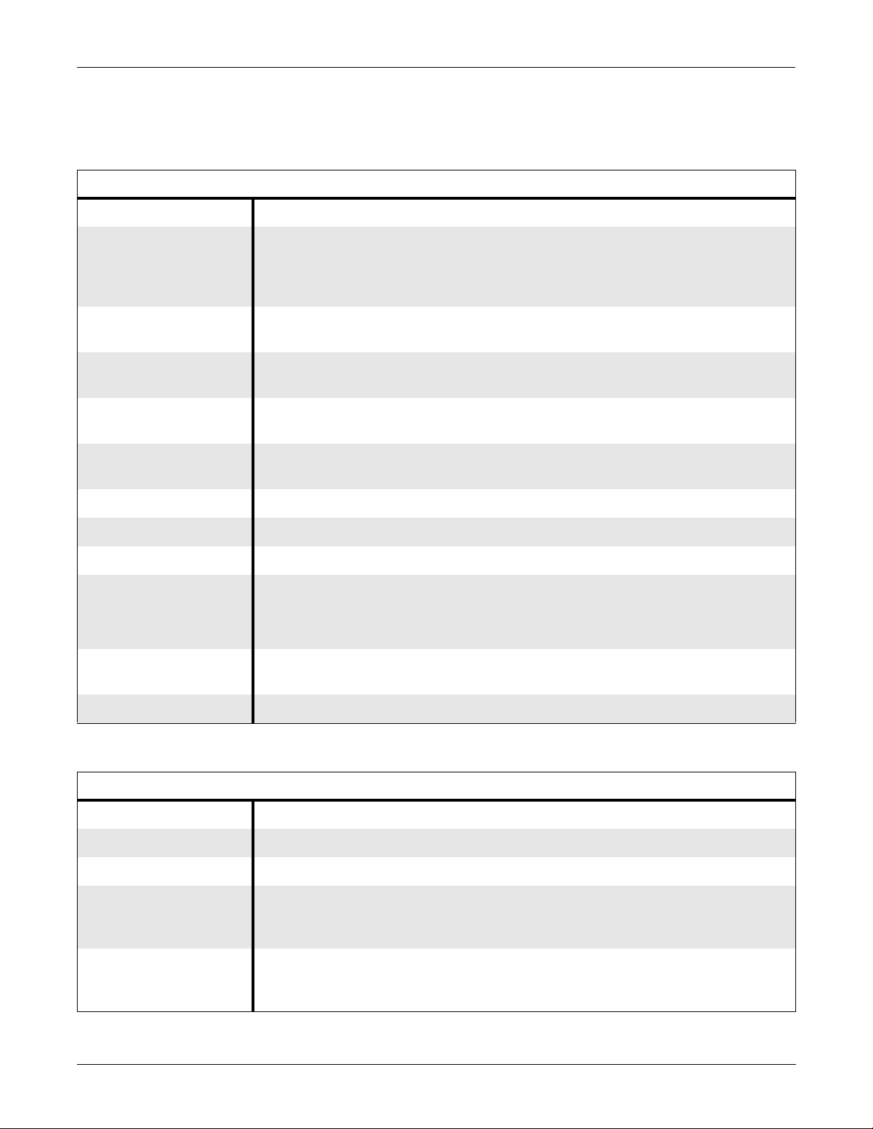
Revision Date Comment
A 28 March 1995 Initial release of this manual.
B 3 October 1995 Added references to Solar 8000 processing unit
C 1 March 1996 Minor corrections
D 15 May 1996 Added references to SolarView remote display controller
E 23 September 1996 Added references to Corometrics TMSS and updated upper assembly
Each page of this manual has a revision letter, located at the bottom of
the page, that identifies its update level. This may be important if you
have different updates to a manual and don’t know which is the most
current.
For the initial release, all pages have the revision letter A. For the first
update of the manual, any changed pages receive the revision letter B.
For the second update, any changed pages receive the revision letter C.
The latest letter of the alphabet added corresponds to the most current
revision. Notice, however, that some pages may skip revision letters, for
example, jump from re vi sion A to re visi on C be caus e they di d not change
in revision B.
Revision History
F 17 June 1998 Added information for revised Service Mode Menu and updated upper
assembly
G 1 September 1999 Removed “Updating Software” from the manual and added UL
information.
H 13 January 2000 Added PRN-50 component to Chapter 2, “Equipment Overview”,
removed references to Corometrics, and updated Chapter 6,
“Configuration” to reflect Reviewing Event Logs.
Manual Purpose
Intended Audience
This manual supplies technical information for service representatives
and technical personnel so they can maintain the equipmnet to the
assembly level. Use it as a guide for maintenance and electrical repairs
considered field repairable. Where necessary the manual identifies
additional sources of relevant information and technical assistance.
See the operator’s manual for the instructions necessary to operate the
equipment safely in accordance with its function and intended use.
For parts lists and schematic diagrams of the PCB assemblies, order the
Solar 7000/8000/View Monitor Data Manual, PN 414993-007.
This manual is intended for service representatives and technical
personnel who maintain, troubleshoot, or repair this equipment.
1-2 Solar 7000/8000/View Patient Monitor Revision H
414993-001
Page 13

Safety Information
INTRODUCTION: Safety Information
Responsibility of the Manufacturer
Intended Use
GE Marquette Medical Systems is responsible for the effects of safety,
reliability, and performance only if:
• Assembly operations, extensions, readjustments, modifications, or
repairs are carried out by persons authorized by GE Marquette.
• The electrical installation of the relevant room complies with the
requirements of the appropriate regulations.
• The equipment is used in accordance with the instructions for use.
Follow the directives stated below when using this device.
• This device is intended for use under the direct supervision of a
licensed health care practitioner.
• This device is not intended for home use.
• Federal law restricts this device to be sold by or on the order of a
physician.
• Contact GE Marquette Medical Systems for information before
connecting any devices to the equipment that are not recommended
in this manual.
• Parts and accessories used must meet the requirements of the
applicable IEC 601 series safety standards, and/or the system
configuration must meet the requirements of the IEC 60601-1-1
medical electrical systems standard.
• P eriodica lly, and when ever t he int egrit y of the de vice is in d oubt, te st
all functions.
• The use of ACCESSORY equipment not complying with the
equivalent safety requirements of this equipment may lead to a
reduced level of safety of the resulting system. Consideration
relating to the choice shall include:
◆ use of the accessory in the PATIENT VICINITY; and
◆ evidence that the safety certification of the ACCESSORY has
been performed in accordance to the appropriate IEC 60601-1
and/or IEC 60601-1-1 harmonized national standard.
• If the installation of the equipment, in the USA, will use 240V rather
than 120V, the source must be a center-tapped, 240V, single-phase
circuit.
Revision H Solar 7000/8000/View Patient Monitor 1-3
414993-001
Page 14
INTRODUCTION: Safety Information
PRESS
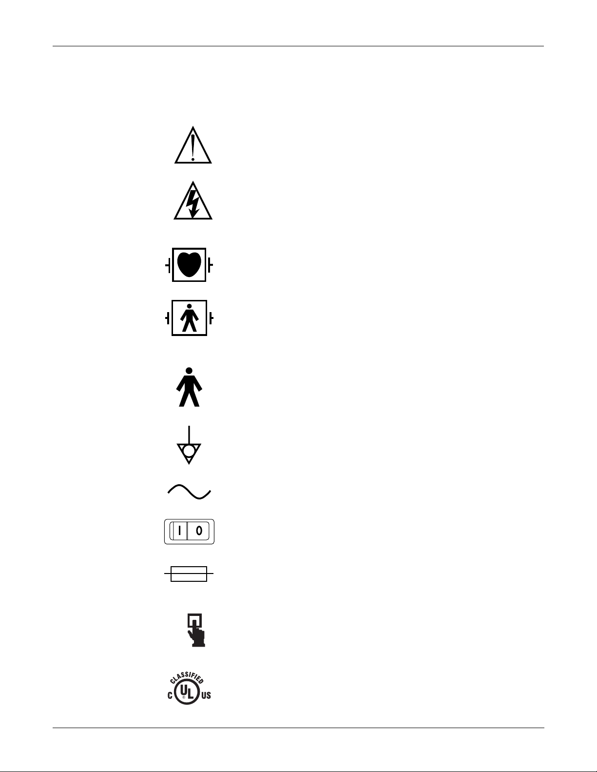
Equipment Symbols
The following symbols appear on the equipment.
NOTE: Some symbols may not appear on all equipment.
ATTENTION: Consult accompanying documents before using the
equipment.
In Europe, this symbol means dangerous or high voltage. In the
United States, this symbol represents the caution notice below:
To reduce the risk of electric shock, do NOT remove cover (or back).
Refer servicing to qualified personnel.
Defibrillator-proof type CF equipment; type CF equipment is
specifically designed for applications where a conductive connection
directly to the heart is established. The paddles indicate the
equipment is defibrillator proof.
Defibrillator-proof type BF equipment; type BF equipment is suitable
for intentional external and internal application to the patient,
excluding direct cardiac application. Type BF equipment is type B
equipment with an F-type isolated (floating) part. The paddles
indicate the equipment is defibrillat or pro o f.
Type B equipment; type B equipment is suitable for intentional
external and internal application to the patient, excluding direct
cardiac application.
Equipotentiality
Alternating current (AC)
Power;
Fuse
Where used, indicates to press to open.
I = ON; O= OFF
Classified by Underwriters Laboratories Inc. with respect to electric
shock, fire, mechanical and other specified hazards, only in
accordance with UL 2601-1, CAN/CSA C22.2 No. 601.1, IEC 60601-1,
and, if required, IEC 60601-2-27, IEC 60601-2-30, IEC 60601-2-34,
IEC 60601-1-1.
1-4 Solar 7000/8000/View Patient Monitor Revision H
414993-001
Page 15

INTRODUCTION: Safety Information
Warnings, Cautions, and Notes
The terms danger, warning, and caution are used throughout this
manual to point out hazards and to designate a degree or level or
seriousness. Familiarize yourself with their definitions and significance.
Hazard is defined as a source of potential injury to a person.
DANGER indicates an imminent hazard which, if not avoided, will
result in death or serious injury.
WARNING indicates a potential hazard or unsafe practice which, if not
avoided, could result in death or serious injury.
CAUTION indicates a potential hazard or unsafe practice which, if not
avoided, could result in minor personal injury or product/property
damage.
NOTE provides application tips or other useful information to assure
that you get the most from your equipment.
Revision H Solar 7000/8000/View Patient Monitor 1-5
414993-001
Page 16

INTRODUCTION: Service Information
Service Information
Service Requirements
Equipment Identification
Follow the service requirements listed below.
• Refer equipment servicing to GE Marquette Medical Systems’
authorized service personnel only.
• Any unauthorized attempt to repair equipment under w arranty voids
that warranty.
• It is the user’s responsibility to report the need for service to GE
Marquette Medical Systems or to one of their authorized agents.
• Failure on the part of the responsible individual, hospital, or
institution using this equipment to implement a satisfactory
maintenance schedule may cause undue equipment failure and
possible health hazards.
• Regular maintenance, irrespective of usage, is essential to ensure
that the equipment will always be functional when required.
Every GE Marquette Medical Systems device has a unique serial number
for identification. A sample of the information found on a serial number
label is shown below.
D 6 XX 0005 G XX
Month
Manufactured
A = January
B = February
C = March
D = April
E = May
F = June
G = July
H = August
J = September
K = October
L = November
M = December
Warranty
Year
Manufactured
6 = 1996
7 = 1997
8 = 1998
(and so on)
Product Code
Two-character
product
descriptor
1 year.
Product
Sequence
Number
Manufacturing
number (of total
units
manufactured.)
Division
F = Cardiology
G = Monitoring
J = G. W. Labs
Device Character istics
One or 2 letters that further
describe the unit, for
example:
P = prototype not
conforming to marketing
specification
R = refurbished equipment
S = special product
documented under Specials
part numbers
U = upgraded unit
1-6 Solar 7000/8000/View Patient Monitor Revision H
414993-001
Page 17

2 EQUIPMENT OVERVIEW
System Components . . . . . . . . . . . . . . . . . . . . . . . . . . . . . . . . . . . . . . . .2-2
What is a Solar 7000/8000 Patient Monitoring System? . . . . . . . . . .2-2
What is the Marquette Unity Network? . . . . . . . . . . . . . . . . . . . . . . . .2-3
What is a Solar 7000 Patient Monitor? . . . . . . . . . . . . . . . . . . . . . . . . 2-4
What is a Solar 8000 Patient Monitor? . . . . . . . . . . . . . . . . . . . . . . . . 2-5
What is a SolarView Remote Display Controller? . . . . . . . . . . . . . . .2-6
What is a Tram-rac Housing? . . . . . . . . . . . . . . . . . . . . . . . . . . . . . . . 2-6
What is a DDW? . . . . . . . . . . . . . . . . . . . . . . . . . . . . . . . . . . . . . . . . . 2-7
What is a PRN 50 Digital Writer? . . . . . . . . . . . . . . . . . . . . . . . . . . . . 2-7
What is a Remote Control? . . . . . . . . . . . . . . . . . . . . . . . . . . . . . . . .2-8
What is a Remote Display? . . . . . . . . . . . . . . . . . . . . . . . . . . . . . . . .2-8
What is a Tram-net Hub Assembly? . . . . . . . . . . . . . . . . . . . . . . . . . . 2-9
What is a Tram-net Interface? . . . . . . . . . . . . . . . . . . . . . . . . . . . . .2-10
What is an Octanet Connectivity Device . . . . . . . . . . . . . . . . . . . . .2-10
What is a TMSS? . . . . . . . . . . . . . . . . . . . . . . . . . . . . . . . . . . . . . . . 2-11
Technical Specifications . . . . . . . . . . . . . . . . . . . . . . . . . . . . . . . . . . . . . 2-12
Preparation for Use . . . . . . . . . . . . . . . . . . . . . . . . . . . . . . . . . . . . . . . . . 2-17
Power Connection . . . . . . . . . . . . . . . . . . . . . . . . . . . . . . . . . . . . . . 2-17
Tram-rac Housing Connection . . . . . . . . . . . . . . . . . . . . . . . . . . . . .2-18
Marquette Unity Network Connection . . . . . . . . . . . . . . . . . . . . . . . . 2-18
Interconnection . . . . . . . . . . . . . . . . . . . . . . . . . . . . . . . . . . . . . . . . .2-19
Tram-rac 4A Housing . . . . . . . . . . . . . . . . . . . . . . . . . . . . . . . . . 2-20
Tram-rac 2 Housing . . . . . . . . . . . . . . . . . . . . . . . . . . . . . . . . . . 2-21
Dual Tram-rac Housings . . . . . . . . . . . . . . . . . . . . . . . . . . . . . .2-22
Octanet . . . . . . . . . . . . . . . . . . . . . . . . . . . . . . . . . . . . . . . . . . . 2-24
DDW . . . . . . . . . . . . . . . . . . . . . . . . . . . . . . . . . . . . . . . . . . . . . 2-24
PRN 50 . . . . . . . . . . . . . . . . . . . . . . . . . . . . . . . . . . . . . . . . . . . 2-25
Local/Remote Displays . . . . . . . . . . . . . . . . . . . . . . . . . . . . . . . 2-27
Cabling Schemes . . . . . . . . . . . . . . . . . . . . . . . . . . . . . . . . . . . . 2-31
Remote Control . . . . . . . . . . . . . . . . . . . . . . . . . . . . . . . . . . . . . 2-34
Tram-net Interface Adapter . . . . . . . . . . . . . . . . . . . . . . . . . . . . 2-35
Octanet Connectivity Device . . . . . . . . . . . . . . . . . . . . . . . . . . . 2-36
TMSS . . . . . . . . . . . . . . . . . . . . . . . . . . . . . . . . . . . . . . . . . . . . . 2-37
Power Up . . . . . . . . . . . . . . . . . . . . . . . . . . . . . . . . . . . . . . . . . . . . . . . .2-38
For all Solar Monitors . . . . . . . . . . . . . . . . . . . . . . . . . . . . . . . . . . . .2-38
For Monochrome Solar 8000 . . . . . . . . . . . . . . . . . . . . . . . . . . . . . .2-38
Configuration . . . . . . . . . . . . . . . . . . . . . . . . . . . . . . . . . . . . . . . . . . 2-38
More About Tram-net Communication . . . . . . . . . . . . . . . . . . . . . . . . . .2-39
Internal Hub . . . . . . . . . . . . . . . . . . . . . . . . . . . . . . . . . . . . . . . . . . .2-39
Tram-net Hub Assembly . . . . . . . . . . . . . . . . . . . . . . . . . . . . . . . . . . 2-40
More About Ethernet Communication . . . . . . . . . . . . . . . . . . . . . . . . . . .2-41
Twisted Pair . . . . . . . . . . . . . . . . . . . . . . . . . . . . . . . . . . . . . . . . . . . 2-41
Concentrator . . . . . . . . . . . . . . . . . . . . . . . . . . . . . . . . . . . . . . . . . . . 2-42
Thin-net /Thick-net . . . . . . . . . . . . . . . . . . . . . . . . . . . . . . . . . . . . . . 2-42
Node . . . . . . . . . . . . . . . . . . . . . . . . . . . . . . . . . . . . . . . . . . . . . . . . .2-42
Segment and Branch . . . . . . . . . . . . . . . . . . . . . . . . . . . . . . . . . . . . 2-42
Repeater . . . . . . . . . . . . . . . . . . . . . . . . . . . . . . . . . . . . . . . . . . . . . . 2-43
Bridge . . . . . . . . . . . . . . . . . . . . . . . . . . . . . . . . . . . . . . . . . . . . . . . .2-43
What is Twisted Pair Cabling (10 Base-T) . . . . . . . . . . . . . . . . . . . . 2-44
Revision H Solar 7000/8000/View Patient Monitor 2-1
414993-001
Page 18
EQUIPMENT OVERVIEW: System Components
System Components
What is a Solar 7000/ 8000 Patient Monitoring System?
The Solar 7000/8000 patient monitoring system is designed to monitor
electrocardiographic, hemodynamic, respiratory, and pulmonary
parameters in the intensive care, coronary care, and operating room
environments of a hospital.
The Solar 7000/8000 patient monitoring system operates with the
Marquette Unity Network or as a system itself. At the patient’s bed, the
Solar 7000/8000 patient monitoring system permits connection of many
peripheral devices from the Solar 7000/8000 monitor.
All Solar 7000/8000 Patient Monitoring Systems include a patient
monitor, at least one patient parameter monitoring module, and one or
more of the following items:
• Tram-rac housing (Tram remote acquisition case),
• DDW (direct digital write r ),
• remote control,
• remote display,
• SolarView remote display, or
• TMSS (Tre nd Memory Storage System)
Shown below is an example of a Solar 7000 patient monitoring system.
2-2 Solar 7000/8000/View Patient Monitor Revision H
414993-001
Page 19

EQUIPMENT OVERVIEW: System Components
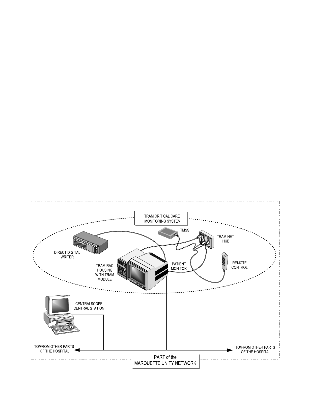
What is the Marquette Unity Network?
The Marquette Unity Network is a comprehensive communication
network which unifies GE Marquette Medical Systems patient
monitoring and data management equipment into an integrated
hospital-wide system. It creates an extended communication system for
efficient information sharing among operating rooms intensive care
units, the emergency room, and other care and diagnostic areas.
Information entered anywhere on the network, via any input device, is
available anywhere else on the network. This is accomplished through
the Ethernet communication hardware in the patient monitor.
An example of part of a Marquette Unity Network is shown bel ow.
Revision H Solar 7000/8000/View Patient Monitor 2-3
414993-001
Page 20
EQUIPMENT OVERVIEW: System Components
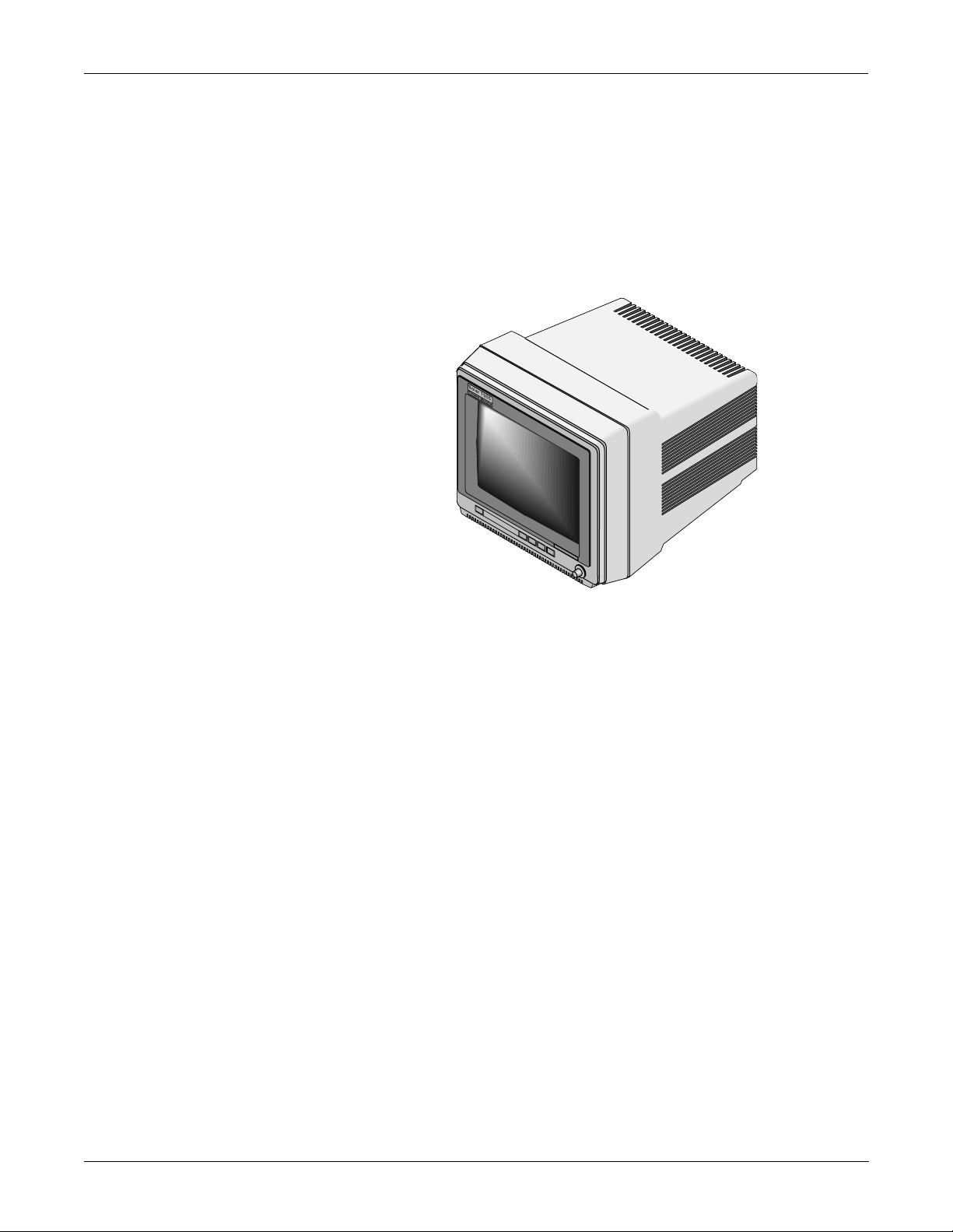
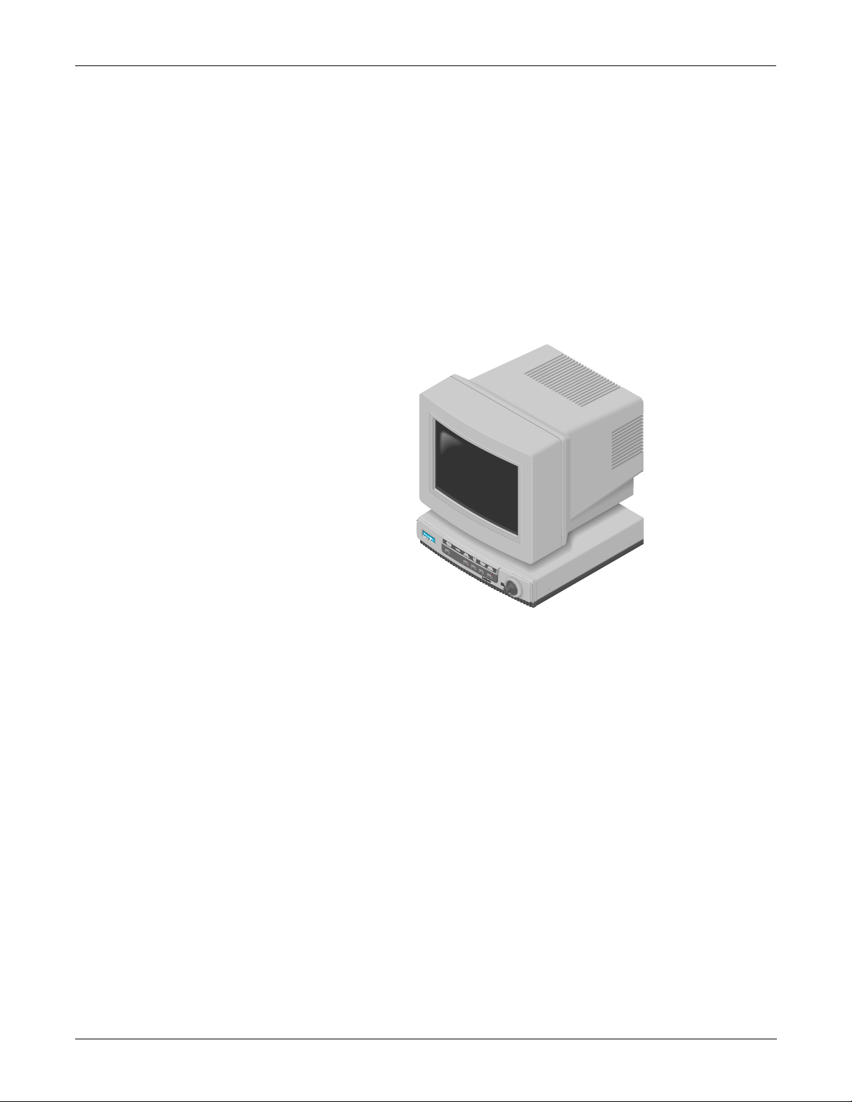
What is a Solar 7000 Patient Monitor?
The Solar 7000 patient monitor is the center of the Solar 7000 Patient
Monitoring System. It is an intelligent terminal, containing the display,
all of the user controls, and processors to communicate with patient
monitor peripherals and analyze patient data. It is capable of displaying
up to eight different waveforms at one time. System software may be
updated by a laptop computer at the monitor or through the Marquette
Unity network using a central station.
Shown below is a Solar 7000 patient monitor.
2-4 Solar 7000/8000/View Patient Monitor Revision H
414993-001
Page 21
EQUIPMENT OVERVIEW: System Components
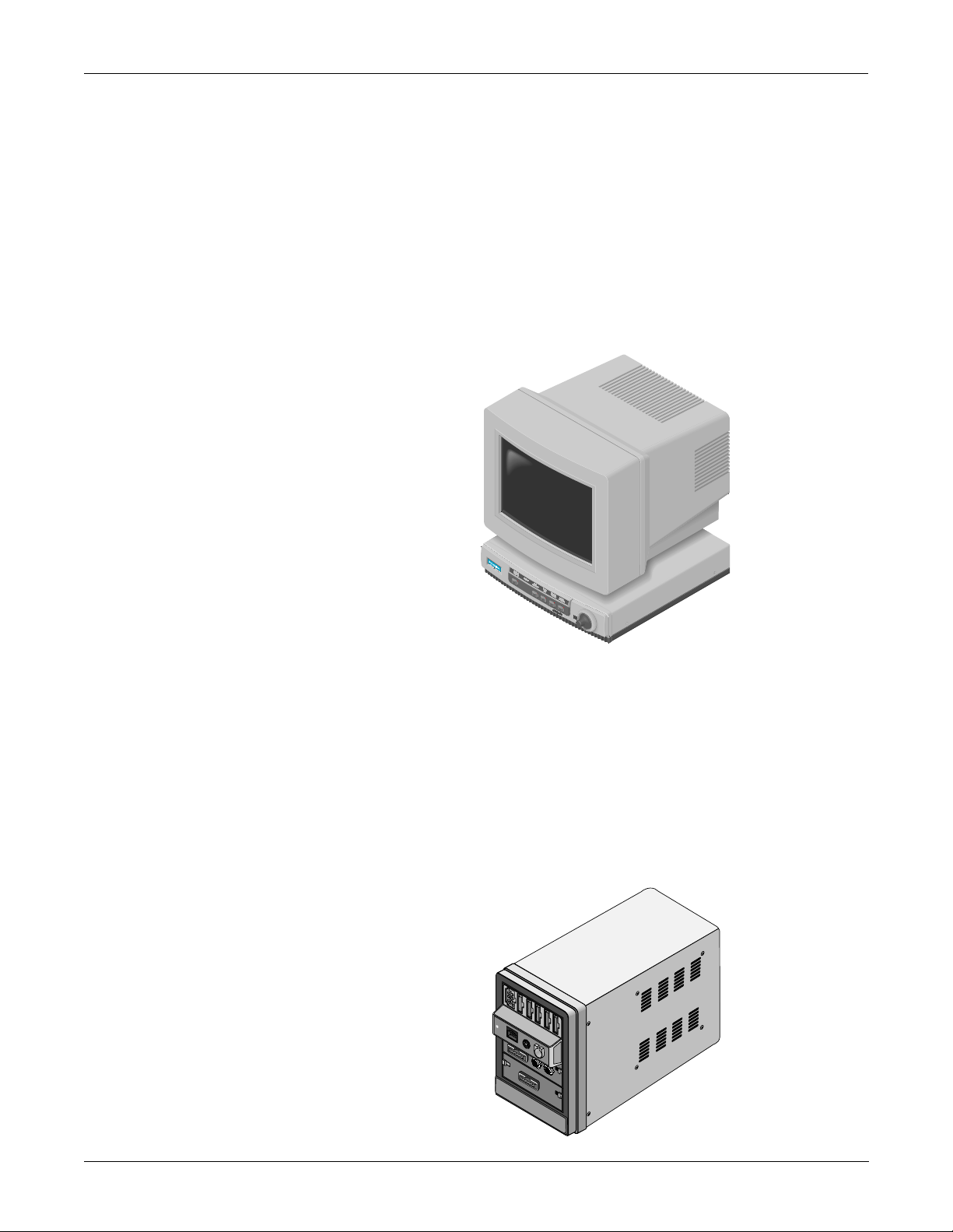
What is a Solar 8000 Patient Monitor?
The Solar 8000 patient monitor consists of a Solar 8000 processing unit
with a compatible display purchased from GE Marquette Medical
Systems or another vendor. (For details about the GE Marquette display,
refer to the 15-Inch Medical-Grade Color Display Service Manual, pn
414993-056.)
The processing unit is the center of the Solar 8000 Patient Monitoring
system. It provides the user controls, processors to communicate with
various patient monitoring modules contained in a Tram-rac housing,
and analyzes patient data. It is capable of di splaying up to eight diff erent
waveforms at one time on a compatible display. System software may be
updated using a laptop computer connected to the Solar 8000 processing
unit or from a central station on the Marquette Unity Network. Shown
below is a generic display and a Solar 8000 processing unit.
Revision H Solar 7000/8000/View Patient Monitor 2-5
414993-001
Page 22
EQUIPMENT OVERVIEW: System Components
What is a SolarView Remote Display Controller?
A SolarView remote display controller resembles a Solar 8000 processing
unit, but it is not connected to a Tram-rac housing with patient
monitoring modules. It consists of a SolarV iew remote display controller
with a compatible display purchased from GE Marquette Medical
Systems or another vendor. (For details about the GE Marquette display,
refer to the 15-Inch Medical-Grade Color Display Service Manual, pn
414993-056.) The controller is connected to the Marquette Unity network
and may be configured to display any patient waveforms broadcasted on
the network for better visibility as either a remote, full-view display or as
an in-room, telemetry display. System software may be updated using a
laptop computer connected to the SolarView remote display controller or
from a central station on the Marquette Unity Network. Shown below is
a generic display and a SolarView remote display controller.
What is a Tram-rac Housing?
The Tram-rac housing (remote acquisition case) acquires patient data for
the patient monitor. The Tram-rac Housing Service Manual, pn404183-
096, has more information. There are two Tram-rac housings available
for the monitor:
• Tram-rac 2 housing, which holds a single Tram module, and
• Tram-rac 4A housing, which holds a Tram module and two additional
Series 7000 input modules.
Shown below is a Tram-rac 4A housing with a Tram module, Series 7000
BP/dual temperature module, and single Series 7000 BP module
inserted.
2-6 Solar 7000/8000/View Patient Monitor Revision H
414993-001
Page 23
EQUIPMENT OVERVIEW: System Components
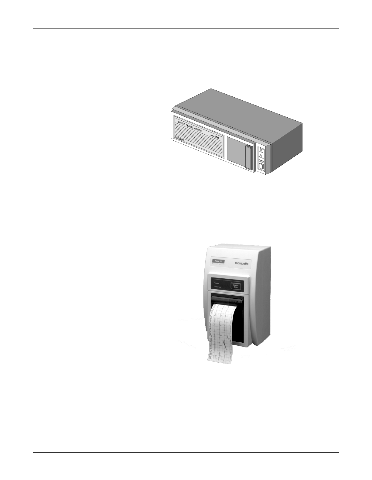
What is a DDW?
What is a PRN 50 Digital Writer?
A Direct Digital Writer (DDW) allows patient data to be printed on a
paper strip. Any parameter or trace that can be monitored at the patient
monitor can also be printed on the DDW. Graphs are initiated
automatically when an alarm has been violated, or they can be initiated
manually at the patient monitor.
A PRN 50 Digital Writer thermally records patient data on a paper strip.
Any parameter or trace that can be monitored on a patient monitor can
be graphed by the writer. Graphs are initiated automatically when an
alarm has been activate d, or they can be initiated manually from a
monitor.
Revision H Solar 7000/8000/View Patient Monitor 2-7
414993-001
Page 24
EQUIPMENT OVERVIEW: System Components
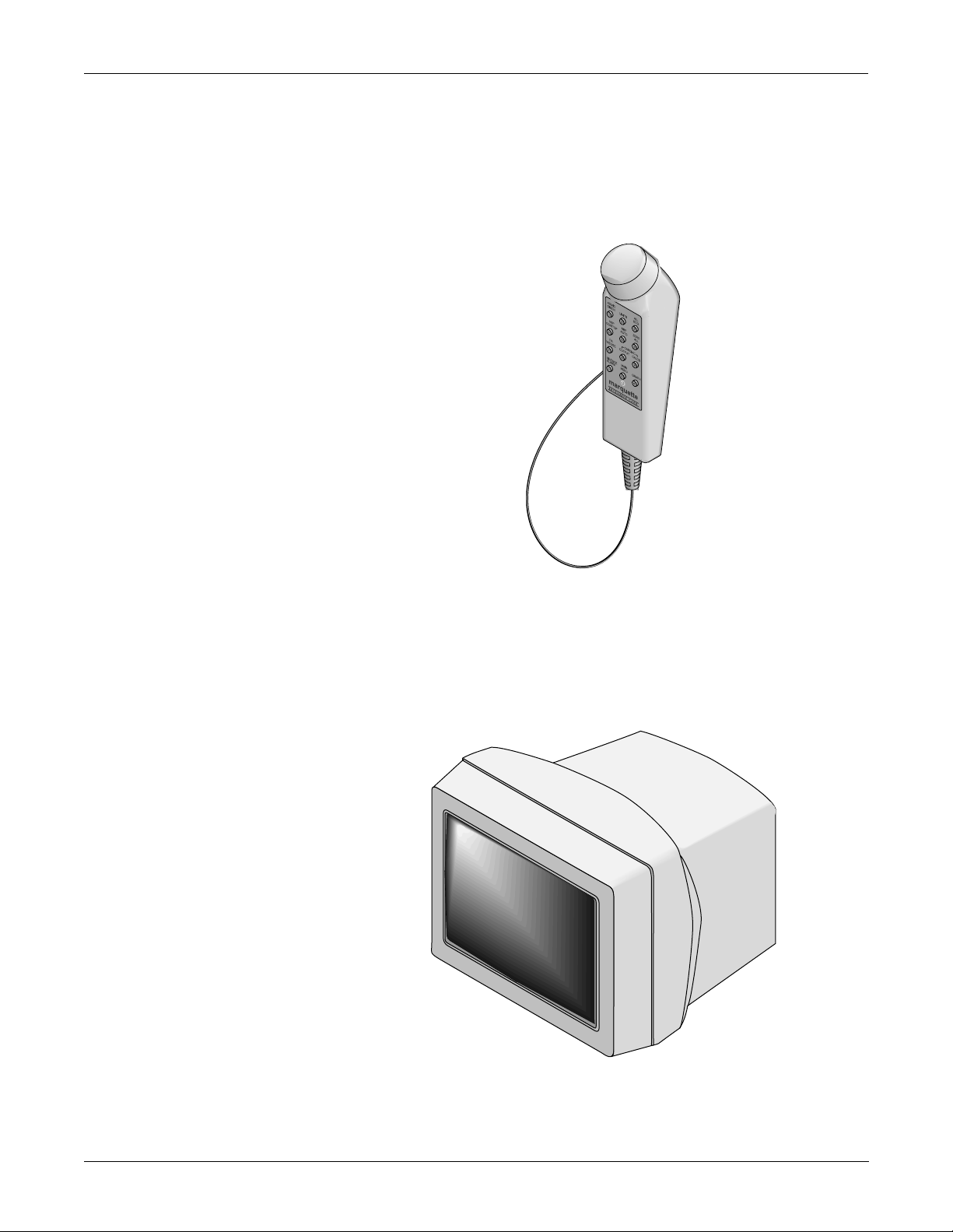
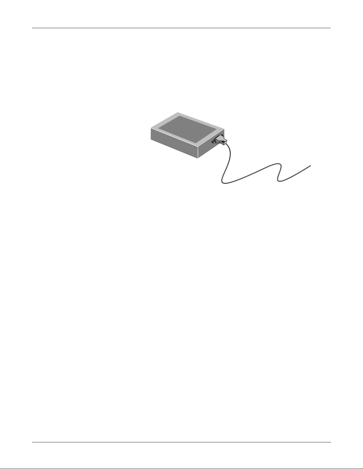
What is a Remote Control?
The remote control duplicates all patient monitor controls on a portable
component with a Trim Knob control. It allows the user to operate the
patient monitor from across a room. The twelve hard keys are configured
for adult, neonatal, or operating room applications. For more details
about the remote control, refer to the Modular Patient Monito r
Accessories Service Manual, pn 404183-150.
What is a Remote Display?
NOTE: An adapter,
pn 405947-002, is
required for cable,
pn 405360-00X, to the
remote display.
A color or monochrome secondary display may be attached directly to the
Solar 7000 patient monitor to display up to eight patient monitor
waveforms for better visibility . It is connected to the video out (RMT VID)
connector at the back of the monitor. F or details about the remote display ,
refer to the Patient Monitor Accessories Service Manual, pn 404183-150.
2-8 Solar 7000/8000/View Patient Monitor Revision H
414993-001
Page 25
EQUIPMENT OVERVIEW: System Components
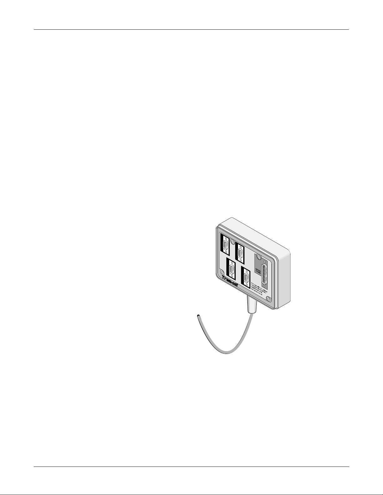
What is a Tram-net Hub Assembly?
If a patient monitor is connected to more than one peripheral device, the
Tram-net hub assembly is used. It connects the communication
processing capabilities inside the patient monitor to other equipment,
much like what a multiple outlet power strip does for ac power.
Peripherals can be connected to the Tram-net hub assembly via serial
cabling. The Tram-net hub assembly extends the patient monitor with a
cable of up to 1.3 meters (4 feet) long.
Note that a 25-pin D-type connector at the rear of the patient monitor is
marked TRAM-NET or ASYNC COMM. This connector handles both
Tram-net and async signals. One end of the Tram-net hub assembly
connects to this connector. At the other end of t he Tram-net hub
assembly, the signals are separated into async and four Tram-net
connectors. The 25-pin red color coded connector handles async for
communication only with an async-only. The four 9-pin blue color coded
connectors are for extending the Tram-net network (blue label). More
details about Tram-net communication will be covered later in this
chapter.
Shown below is a Tram-net hub assembly . F or details about the Tram-net
hub assembly, refer to the Modular Patient Monitor Accessories Service
Manual, pn 404183-150.
Revision H Solar 7000/8000/View Patient Monitor 2-9
414993-001
Page 26
EQUIPMENT OVERVIEW: System Components
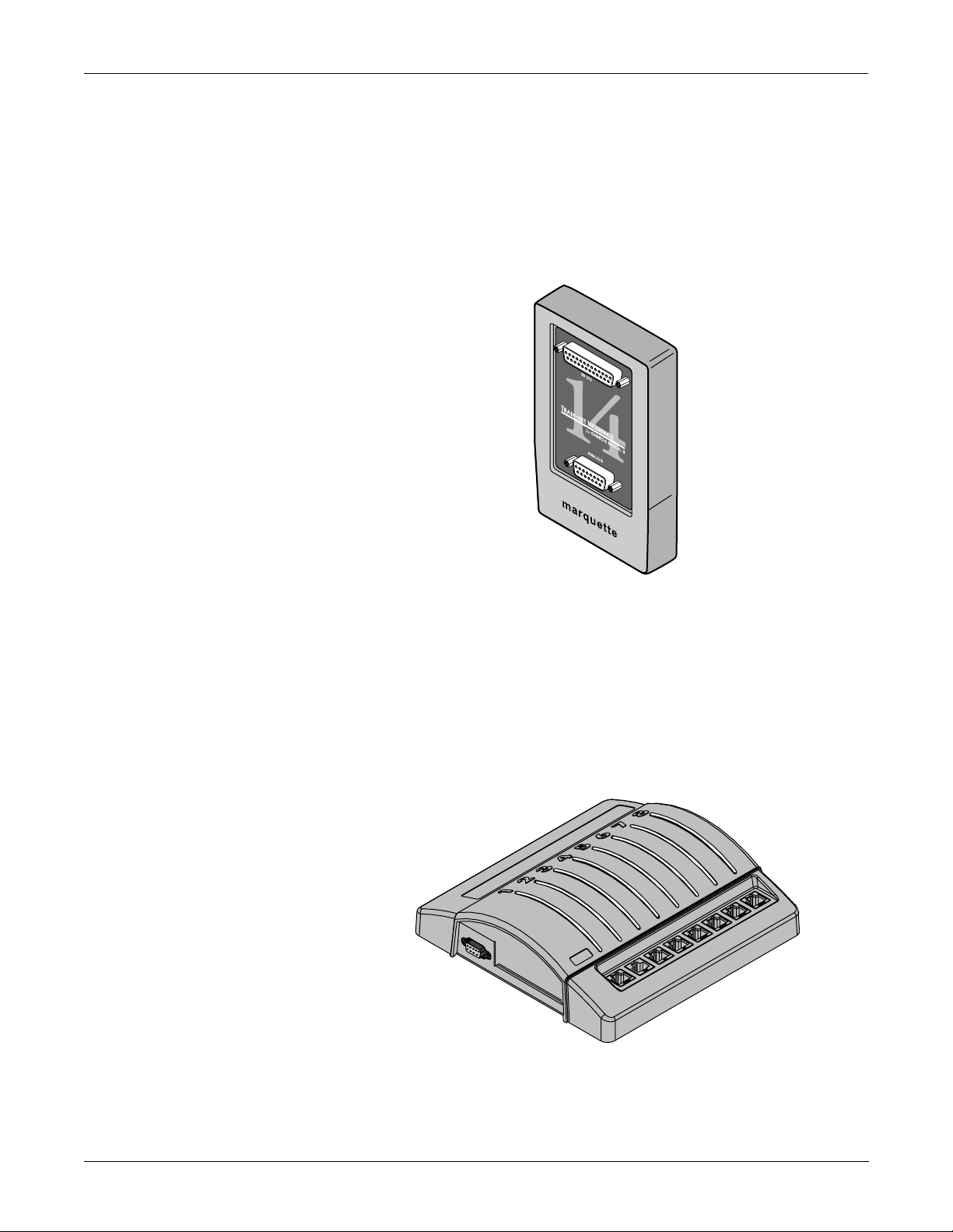
What is a Tram-net Interface?
The Tram-net interface adapter connects a specific device to the Solar
7000/8000 patient monitoring system using Tram-net communication.
Each adapter is preprogrammed at the factory to interface with a specific
device manufactured by a company other than GE Marquette Medical
Systems. In most cases, the Tram-net interface adapter requires a Tramnet hub to connect with the Tram-net communication network. For more
details about the Tram-net interface adapter, refer to the Modular
Patient Monitor Accessories Service Manual, pn 404183-150.
What is an Octanet Connectivity Device?
The Octanet Connectivity Device acquires digital data from eight
individually isolated serial ports. The data is collected from up to eight of
devices not manufactured by GE Marquette Medical Systems. The
Octanet Connectivity Device processes the patient data from the
peripheral devices and transmits the formatted data to the Solar patient
monitor . For more details about the Octanet Connectivity Device, refer to
the Octanet Connectivity Device Service Manual, pn 418264-003.
2-10 Solar 7000/8000/View Patient Monitor Revision H
414993-001
Page 27
EQUIPMENT OVERVIEW: System Components
What is a TMSS?
The Trend Memory Storage System (TMSS) is an opt ional device that
stores up to 24 hours of trend data for the CRG Plus display—six hours
at a time. This feature is available with V3 software or later. The stored
CRG data is used in the overall analysis of a patient. Analyzing trend
waveforms permits the ability to view both subtle and dramatic changes
in the patient’s vital signs. It also enables the clinician to correlate
changes of one parameter with respect to ano ther. For more de tails about
the TMSS, refer to the Model 7024 Product Manual, pn 13703AA-000.
Revision H Solar 7000/8000/View Patient Monitor 2-11
414993-001
Page 28
EQUIPMENT OVERVIEW: Technical Specifications
Technical Specifications
Display Specifications
Item Description
Size Solar 7000 Monitor: 12-inch (measured diagonally)
Solar 8000 Processing Unit: Display is ordered separately and may vary.
SolarView Remote Display Controller: Display is ordered separately and
may vary.
Type Solar 7000 Monitor: High-definition Raster scan for waveforms and
alphanumerics
Resolution Solar 7000 Color Monitor: 1024 pixels wide by 512 pixels high
Solar 7000 Monochrome Monitor: 1024 pixels wide by 512 pixels high
Traces Solar 7000 Monitor: Number of traces: 1 to 8
Solar 7000 Monitor: Number of seconds/trace: 6.5 at 25 mm/sec
Phosphor Solar 7000 C olor Monitor: P22
Solar 7000 Monochrome: Monitor: P218
Sweep Speed Solar 7000 Monitor: 25 mm/sec (meets all ANSI/AAMI specifications)
Frequency Response Limited by input response of da ta acquisition device
Linearity Solar 7000 Monitor:1% of picture height
Waveform Display
Options
■ Full
■ Individual
■ CRG Plus
Information Window Display all non-real time information without obstructing the display of
real-time information
Display Organization Prioritized by pa rameter
Processing Specifications
Item Description
Main Processor Motorola MC68EN360, 32-Bit, 25 MHz
Graphics Processor Texas Instrument TMS34010, 16-Bit, 46.7 MHz
Tram-net
Intel 82596CA, 32-Bit, 25 MHz
Communication
Processor
LAN (Ethernet)
Integrated into the Motorola MC68EN360 processor
Communication
Processor
2-12 Solar 7000/8000/View Patient Monitor Revision H
414993-001
Page 29
EQUIPMENT OVERVIEW: Technical Specifications
Alarm Specifications
Item Description
Classification Patient status alarms have 4 levels:
■ Crisis
■ Warning
■ Advisory
■ Message
System alarms have 2 levels:
■ Warning
■ Advisory
Alarms Notification Audible and visual, dependent on level
Display of Alarm
All limits are viewable and graphable
Information
Silencing Only current alarm for 1 minute
Alarm pause:
■ 5 minutes in adult ICU mode
■ 3 minutes in neonatal mode
■ 5 minutes, 15 minutes, or permanent alarm pause in OR mode
Continuous Display of
All parameters, one set of limits
Limits
Control Specificat ions
Item Description
Trim Knob Control Single control operation of all display functions
Five Hard Keys
■ Display On/Off
■ Silence Alarm
■ Grap h Go/Stop
■ NBP Go/Stop
■ Zero All
Revision H Solar 7000/8000/View Patient Monitor 2-13
414993-001
Page 30
EQUIPMENT OVERVIEW: Technical Specifications
Environmental Specifications
Item Description
Powe r Requirements Solar 7000 Color Monitor:
■ 110 ± 11 VAC, 50/60-Hz, single phase
■ 120 ± 12 VAC, 50/60-Hz, single phase
■ 220-230 ± 22 VAC, 50/60-Hz, single phase
■ 240 ± 24 VAC, 50/60-Hz, single phase
Solar 7000 Monochrome: Monitor and Solar 8000 Processing Unit
■ 110 ± 20 VAC, 50/60-Hz, single phase
■ 220-230 ± 40 VAC, 50/60-Hz, single phase
Power Consumption Solar 7000 Color Monitor: 200 W (180 W for a Tram-rac housing with power
supply connected)
Solar 7000 Monochrome Monitor: 120 W (100 W for a Tram-rac housing with
power supply connected)
Solar 8000 Processing Unit: 100W (maximum)
SolarView Remote Display Controller: 25W (maximum)
Low Voltage Shutdown Solar 7000 Color Monitor: 88 VAC/106 VAC/196 VAC/214 VAC
Solar 7000 Monochrome Monitor: 85 VAC/170 VAC
Solar 8000 Processing Unit: 90 VAC/190 VAC
SolarView Remote Display Controller: 90 VAC/190 VAC
Cooling Solar 7000 Color Monitor: Forced convection
Solar 7000 Monochrome Monitor and Solar 8000 Processing Unit: Natural
convection
Heat Dissipation Solar 7000 Color Monitor: 680 Btu/hr (200 W)
Solar 7000 Monochrome Monitor: 409 Btu/hr (120 W)
Solar 8000 Processing Unit: 100 Btu/hr (30W)
SolarView Remote Display Controller: 50 Btu/hr (15W)
Operating Conditions
■ Ambient
Temperature
Solar 7000 Monitor: 10°C to 35°C (50°F to 95°F)
Solar 8000 Processing Unit: 10°C to 40°C (50°F to 104°F)
SolarView Remote Display Controller: 10°C to 40°C (50°F to 104°F)
■ Relative Humidity
Solar 7000 Monitor: 15% to 95% (noncondensing)
Solar 8000 Processing Unit: 15% to 95% (noncondensing)
SolarView Remote Display Controller: 15% to 95% (noncondensing)
Storage Conditions
■ Temperature
Solar 7000 Monitor: –10°C to 50°C (14°F to 122°F)
Solar 8000 Processing Unit: –40°C to 70°C (–40F° to °158F)
SolarView Remote Display Controller: –40°C to 70°C (–40F° to °158F)
■ Relative Humidity
Solar 7000 Monitor: 0% to 95% (noncondensing)
Solar 8000 Processing Unit: 15% to 95% (noncondensing)
SolarView Remote Display Controller: 15% to 95% (noncondensing)
2-14 Solar 7000/8000/View Patient Monitor Revision H
414993-001
Page 31

EQUIPMENT OVERVIEW: Technical Specifications
Physical Specifications
Item Description
Height Solar 7000 Monitor: 31.1 cm (12.3 in)
Solar 8000 Processing Unit: 8.1 (3.2 in)
SolarView Remote Display Controller: 8.1 (3.2 in)
Width Solar 7000 Monitor: 33.4 cm (13.5 in)
Solar 8000 Processing Unit: 33.6 cm (13.3 in)
SolarView Remote Display Controller: 33.6 cm (13.3 in)
Depth Solar 7000 Color Monitor: 55.2 cm (21.7 in)
Solar 7000 Monochrome Monitor: 39.9 cm (15.7)
Solar 8000 Processing Unit: 34.9 cm (13.8 in)
SolarView Remote Display Controller: 34.9 cm (13.8 in)
Weight Solar 7000 Color Monitor: 22 kg (48 lb)
Solar 7000 Monochrome Monitor: 13.3 kg (29.4 lb)
Solar 8000 Processing Unit: 5.4 kg (12.0 lb)
SolarView Remote Display Controller: 5.4 kg (12.0 lb)
Minimum Enclosure
Requirements
(Interior)
Height: 10.7 cm (4.2 in)
Width: 38.9 cm (15.3 in)
Depth: 51.8 cm (20.4 in)
Item Description
Safety Standards Solar 7000 Monitor:
■ UL544 Listed
■ UL Listed for CSA C22.2 No. 125
■ IEC 60601-1 Certified
■ CE Marking for the 93/42/EEC Medical Device Directive (Refer to operator’s
manual for CE Marking specifics.)
Solar 8000 Processing Unit and SolarView Remote Display Controller:
■ UL 2601-1 Classified
■ UL Classified for CAN/CSA C22.2 No. 601.1
■ IEC 60601-1 Certified
■ CE Marking for the 93/42/EEC Medical Device Directive (Refer to operator’s
manual for CE Marking specifics.)
Certification
Revision H Solar 7000/8000/View Patient Monitor 2-15
414993-001
Page 32

EQUIPMENT OVERVIEW: Technical Specifications
Classification
Item Description
Type of protection
Class I Equipment
against electrical shock
Degree of protection
Type B Applies Part
against electrical shock
Degree of protection
against harmful ingress
Ordinary Equipment (enclosed equipment without protection against ingress of
water)
of water
Degree of safety of
application in the
Equipment not suitable for use in the presence of a flammabl e anesthetic
mixture with air or with oxygen or nitrous oxide.
presence of a flammable
anesthetic mixture with
air or with oxygen or
nitrous oxide
Method(s) of
Not Applicable
sterilization or
disinfection
recommended by the
manufacturer
Mode of operation Continuous operation
2-16 Solar 7000/8000/View Patient Monitor Revision H
414993-001
Page 33

EQUIPMENT OVERVIEW: Preparation for Use
Preparation for Use
Power Connection
For the Solar 7000 monitor, connect the power cord to the power supply
inlet and anchor the cord with the restraining clip and screw.
For the Solar 8000 processing unit or SolarView remote display
controller, connect the power cord to the power supply inlet and anchor
the cord with the restraining clip and screw.
Revision H Solar 7000/8000/View Patient Monitor 2-17
414993-001
Page 34

EQUIPMENT OVERVIEW: Preparation for Use
Tram-rac Housing Connection
Marquette Unity Network Connection
If a Tram-rac power supply is used, connect the power cord as shown
below.
For the Solar 7000/8000 monitor or SolarView remote display controller,
connect the Marquette Unity network to the Ethernet connector with kit,
pn 414292-001, as shown below.
1. Remove four jackscrews from
connectors shown.
2. Install two screws from kit to
secure ETHERNET
connector to chassis.
3. Install two screws to connect
transceiver bracket to
transceiver.
4. Use two jackscrews removed
earlier to mount transceiver
and bracket to ETHERNET
connector.
2-18 Solar 7000/8000/View Patient Monitor Revision H
414993-001
Page 35

EQUIPMENT OVERVIEW: Preparation for Use
Interconnection
The Solar 7000/8000 patient monitor or SolarView remote display
controller has six communication connectors to accomodate your
monitoring system.
• ASYNC COMM connects to a DDW or remote control, or to download
new software. SolarView remote display controller does not use this
function.
• TRAM-NET combines Tram async and the Tram-net network for
communication with many bedside peripherals, i.e. Tram-net hub,
Tram-rac housing, or remote control. SolarView remote display
controller does not use this function.
• ETHERNET is the Marquette Unity Network connection that
provides faster hospital wide communication.
• Remote alarm (RMT ALM) provides relay contact closure for “Leve l
I” alarms to an alarm annunciator.
• For the Solar 7000 monitor, remote display (RMT VID) connects to a
secondary remote display. For the Solar 8000 processing unit or
SolarView remote display controller, video (VID) connects to the local
display.
• RS-232 is for future use.
WARNING
Connect devices solely manufactured by GE Marquette
Medical Systems directly to the Marquette Unity
Network. Contact MMS—Technical Support before
connecting equipment from other manufacturers.
Revision H Solar 7000/8000/View Patient Monitor 2-19
414993-001
Page 36

EQUIPMENT OVERVIEW: Preparation for Use
Tram-rac 4A Housing
Shown below is the connection from the Tram-rac 4A housing to a Solar
monitor with and without a Tram-net hub connection.
Solar 7000 Patient Monitor
Solar 8000 Patient Monitor
2-20 Solar 7000/8000/View Patient Monitor Revision H
414993-001
Page 37

EQUIPMENT OVERVIEW: Preparation for Use
Tram-rac 2 Housing
Shown below is the connection from the Tram-rac 2 housing to a Solar
monitor with and without a Tram-net hub connection.
Solar 7000 Patient Monitor
Solar 8000 Patient Monitor
Revision H Solar 7000/8000/View Patient Monitor 2-21
414993-001
Page 38

EQUIPMENT OVERVIEW: Preparation for Use
Dual Tram-rac Housings
The Solar patient monitor may support two Tram-rac housings.
The right most Tram-net connector may be connected to the following:
• a monitor or
• a Tram-net hub,
The center Tram-net connector may be connected to the following:
• a remote control or
• to another Tram-rac 4A housing with a power supply.
NOTE: The Tram-rac housing furthest from the monitor must have a
power supply.
Shown below are examples of how to connect dual Tram-rac housings to a
Solar 7000 patient monitor.
2-22 Solar 7000/8000/View Patient Monitor Revision H
414993-001
Page 39

EQUIPMENT OVERVIEW: Preparation for Use
Shown below are examples of how to connect dual Tram-rac housings to a
Solar 8000 patient monitor.
Revision H Solar 7000/8000/View Patient Monitor 2-23
414993-001
Page 40

EQUIPMENT OVERVIEW: Preparation for Use
Octanet
Shown below is the connection from the Octanet to a Solar monitor with
a Tram-net hub connection.
Solar 7000 Patient Monitor
Solar 8000 Patient Monitor
DDW
The DDW connects between the ASYNC COMM ports of the DDW and
the Solar 7000 or 8000 patient monitor. Due to continuing product
innovation, your DDW may be different from that illustrated below.
2-24 Solar 7000/8000/View Patient Monitor Revision H
414993-001
Page 41

EQUIPMENT OVERVIEW: Preparation for Use
PRN 50
The PRN 50 Digital W riter conne cts between t he ASYNC COMM ports of
the PRN 50 Digital Writer and the Solar 7000 or 8000 monitor. Shown
below is the connection of the PRN 50 Digital Writer to Solar 7000 or
8000 monitor.
Solar 7000 Patient Monitor
Solar 8000 Patient Monitor
Revision H Solar 7000/8000/View Patient Monitor 2-25
414993-001
Page 42

EQUIPMENT OVERVIEW: Preparation for Use
The PRN 50 Digital Writer connects between AutoPort on the PRN 50
Digital Writer and the TRAM-NET ports of the Solar 7000 or 8000
monitor when using the Octanet. Shown below is the connection of the
PRN 50 Digital Writer to Solar 7000 or 8000 monitor with a Tram-net
hub and Octanet connection.
Solar 7000 Patient Monitor
Solar 8000 Patient Monitor
2-26 Solar 7000/8000/View Patient Monitor Revision H
414993-001
Page 43

EQUIPMENT OVERVIEW: Preparation for Use
Local/Remote Displays
The Solar 7000 has its own internal local display, but a Solar 8000
system requires a medical-grade display that meets UL and IEC
specifications. If a non-medical computer-grade display is used, an
isolation transformer (or floating power supply) is required regardless if
the computer-grade display meets the leakage current specifications on
its own.
The party assembling or modifying the medical electrical system is
responsible to insure compliance with IEC 601-1-1. Therefore, if GE
Marquette installs a Solar 8000 system with a computer-grade display,
GE Marquette is responsible for meeting the specification. As a result GE
Marquette will only:
• Install medical-grade displays that it recommends, or
• Install computer-grade displays with appropriate isolation
transformers (power conditioners).
NOTE
In an OR or other locations already having an isolated
power system, the use o f an isolat ing transfo rmer (powe r
conditioner) is redundant, and therefore may not be
necessary for patient isolation.
Revision H Solar 7000/8000/View Patient Monitor 2-27
414993-001
Page 44

EQUIPMENT OVERVIEW: Preparation for Use
FPD (Flat Panel Display) Interconnection
To connect a FPD , a medical-g rade power supply is required. Connect the
FPD to the VID 15-pin connector on the Solar 8000 processing unit.
Connect the power supply to the pow er jack of the FPD as shown below.
Connect both po wer cords from both units to the AC outlet.
2-28 Solar 7000/8000/View Patient Monitor Revision H
414993-001
Page 45

EQUIPMENT OVERVIEW: Preparation for Use
Remote Display Interconnection
Shown below are examples of how to connect a remote display to a Solar
7000 patient monitor.
• Display with D style Connector •
• Display with BNC Connectors •
Revision H Solar 7000/8000/View Patient Monitor 2-29
414993-001
Page 46

EQUIPMENT OVERVIEW: Preparation for Use
Solar 8000 Local and Remote Display Interconnection
Shown below are examples of how to connect a local display to a Solar
8000 patient monitor or SolarView remote display controller.
• Display with D style Connector •
• Display with BNC Connectors •
2-30 Solar 7000/8000/View Patient Monitor Revision H
414993-001
Page 47

EQUIPMENT OVERVIEW: Preparation for Use
Cabling Schemes
Select one of the interconnection schemes described after following the
steps below.
1. Determine which display you have in the left column.
2. Match your display’s connector with the installation required.
3. Determine the distance from the remote display to the monitor.
4. Select the appropriate type of installation.
Direct or Wallplate Connection
Use the following interconnection scheme for a remote display requiring
an interface cable to the patient monitor shorter than 155 feet.
Revision H Solar 7000/8000/View Patient Monitor 2-31
414993-001
Page 48

EQUIPMENT OVERVIEW: Preparation for Use
Multiple Displays
Use the following interconnection scheme for a remote display requiring
an interface cable to the patient monitor shorter than155 feet.
2-32 Solar 7000/8000/View Patient Monitor Revision H
414993-001
Page 49

EQUIPMENT OVERVIEW: Preparation for Use
Cabling Over 155 Feet
Use the following interconnection scheme for a remote display requiring
an interface cable to the patient monitor longer than 155 feet.
Revision H Solar 7000/8000/View Patient Monitor 2-33
414993-001
Page 50

EQUIPMENT OVERVIEW: Preparation for Use
Remote Control
Shown below are examples of how to connect a remote control to a Solar
7000 or 8000 patient monitor with and without a Tram-net hub.
2-34 Solar 7000/8000/View Patient Monitor Revision H
414993-001
Page 51

EQUIPMENT OVERVIEW: Preparation for Use
Tram-net Interface Adapter
Shown below are examples of how to connect a Tram-net interface
adapter to a Solar 7000 or Solar 8000 patient monitor.
Revision H Solar 7000/8000/View Patient Monitor 2-35
414993-001
Page 52

EQUIPMENT OVERVIEW: Preparation for Use
Octanet Connectivity Device
Shown below are examples of how to connect a Octanet Connectivity
Device to a Solar 7000 or Solar 8000 patient monitor. For more details
about the Octanet Connectivity Device, refer to the Octanet Connectivity
Device Service Manual, pn 418264-003.
PATIENT ROOM TRAM-NET
Tram-rac
Housing
Octanet
Connectivity
Device
Tram-net
Hub
Adapter
Peripheral
Solar 8000
Patient Monitor
Bedside
Devices
Ethernet
Communication
Serial
Communication
RS232
2-36 Solar 7000/8000/View Patient Monitor Revision H
414993-001
Page 53

EQUIPMENT OVERVIEW: Preparation for Use
TMSS
Shown below are examples of how to connect a Trend Memory Storage
System (TMSS) to a Solar 7000 or Solar 8000 patient monitor.
CAUTION
Always turn the monitor’s main power off before
connecting or disconnecting the TMSS. Refer to the
Model 7024 Product Manual, pn 13703AA-000, for
installation instructions.
Revision H Solar 7000/8000/View Patient Monitor 2-37
414993-001
Page 54

Power Up
EQUIPMENT OVERVIEW: Power Up
For all Solar Monitors
For Monochrome
Solar 8000
After all connections are made, use the following power up sequence.
1. Turn the rear switch of the Solar 7000 monitor or Solar 8000
processing unit or SolarView remote display controller to ON (1). The
power LED on front of the unit should be illuminated.
2. If the display does not illuminate, press the DISPLAY ON/OFF
button ON.
NOTE: The DISPLAY ON/OFF button is not a power switch, but it is
used as a screen saver switch.
3. The following sequence of events should follow.
◆ The display will blank while it is booting up.
◆ The MAIN menu should appear on the display.
◆ If the display remains completely blank or resets
intermittently, there is a serious hardware failure. Refer to
“Troubleshooting Procedure” in Chapter 4 : “ Tro uble shooting.”
After any cold start, the display will default to color video. For a
monochrome display, access the video option by executing the following
menu sequence starting from the MAIN menu:
MONITOR SETUP
SERVICE MODE
Password
Enter day and month from monitor screen with leading zeros.
(July 4 = 0407)
HARDWARE TEST
REMOTE VIDEO
Select MONOCHROME for a monochrome display.
CAUTION
If the Solar 8000 processing unit or SolarView remote
display controller is cold started, the video selection
defaults to color. Red and blue hues will not be
distinguishable on a monochrome display. Reselect
monochrome in the SERVICE MODE menu.
Configuration
2-38 Solar 7000/8000/View Patient Monitor Revision H
The monitor will need to be configured at this time. Refer to “Configuring
a Monitor” in Chapter 6: “Configuration.”
414993-001
Page 55

EQUIPMENT OVERVIEW: More About Tram-net Communication
More About Tram-net Communication
The Solar patient monitor uses two distinct local area networks:
• Tram-net communication, and
• Ethernet communication.
To avoid confusion, consider Tram-net as a small area network (SAN)
contained in one room or a t the pat ient bedsi de. Co nsider Et hernet as t he
local area network (LAN) for room to room communication or
communication between patient monitors, central stations, and other GE
Marquette equipment throughout the hospital.
This local area network links all patient monitors, central stations, and
other GE Marquette equipment throughout the hospital.
The 25-pin connector makes a Tram-net small area network available for
the peripheral devices. The Tram-net controller resides on the same bus
as the main processor which provides efficient data transfer by sharing
main memory.
Internal Hub
Tram-net is a small network that offers ample flexibility, a high rate of
communication, and relatively inexpensive cabling. Data is transmitted
at the rate of 921.6K bits per second. It uses a star topology, sometimes
referred to as a rooted tree topology. This means that the wiring of the
network can be pictured as a star or a series of stars. The center of each
star is called a hub, and the points of the star are called nodes. There are
cables between the nodes and the hubs, but no cables exist between
nodes.
NOTE: Do not confuse the internal hub or node with the Tram-net hub
assembly discussed earlier as a system component. The hub
described in these paragraphs refers to the electronic
distribution point of data.
Revision H Solar 7000/8000/View Patient Monitor 2-39
414993-001
Page 56

EQUIPMENT OVERVIEW: More About Tram-net Communication
Data is acquired at a node, and is transmitted through a hub to all the
other nodes. Each node has an address so data will be received by the
node with the correct destination address. It is impossible for a node to
communicate with another node without the data going through a hub
somewhere along its journey. The hub controls all of the data ‘traffic’ in
the system.
In a Tram-net system, the head hub is contained in the patient monitor,
but there will be intermediate hubs in the Tram-rac housing and Tram
module as well.
Tram-net Hub Assembly
If more than one peripheral is connected to Tram-net, a Tram-net hub
assembly is required. The Tram-net hub assembly simply adds
connectors as more nodes to the patient monitor’ s internal hub. The
nodes of the star in the Tram-net system can be patient monitor
peripherals like the remote control, or Tram-rac housing.
The Tram-net hub assembly extends the communication data and power
between the monitor and its peripherals. If the peripheral draws more
than 3.0 amperes of current, the maximum cable length will be 6.0
meters (20 feet). If the current draw of the peripheral is less, the cable
can be longer. The maximum serial cable length may be up to 61 meters
(200 feet) on peripherals with no power consumption.
2-40 Solar 7000/8000/View Patient Monitor Revision H
414993-001
Page 57

EQUIPMENT OVERVIEW: More About Ethernet Communication
More About Ethernet Communication
Ethernet is a local area network used as the main link of the Marquette
Unity network, a comprehensive information communication system.
The Marquette Unity network offers the high rate of communication of
10 megabits per second. The 15-pin Ethernet connector connects to an
Ethernet transceiver directly or via a transceiver cable. This local area
network links all patient monitors, central stations, and other GE
Marquette equipment throughout the hospital. Depending upon the
construction of the hospital, thick-net, thin-net, or twisted pair cabling is
used.
Twisted Pair
Twisted pair is the most popular cabling because it is easy to install and
flexible to work with. It uses the star topology with a concentrator as the
hub of the segment. Each of the network devices is connected directly to
the concentrator so longer lengths of cable are required. A maximum of
100 meters or 328 feet is the longest length of twisted pair cable used.
The number of devices is limited to the amount of connectors at the
concentrator. More details regarding twisted pair cable is described later
in this chapter.
Revision H Solar 7000/8000/View Patient Monitor 2-41
414993-001
Page 58

EQUIPMENT OVERVIEW: More About Ethernet Communication
Concentrator
Thin-net /Thick-net
Node
Segment and Branch
The concentrator is simply a transceiver that passes all network data
between any two branc hes in the LAN. Note that the concentrator passes
all network data between the two branches, regardless of whether or not
one node is sending data to another node on the same branch.
Thick-net and thin-net is not the most recommended type of network, but
are used in special situations. Both thick-net and thin-net use a bus
topology and connect any nu mber of d evi ces. Each device i s tappe d int o a
straight data bus or trunk. A thick-net or thin-net cable is used for the
main trunk to provide fast data transmission, but is difficult to install
and harder to work with.
Each network device or node is assigned an address number and requires
a transceiver to interface between the network device and the network.
For thick-net and thin-net cabling a transceiver and a serial drop cable
connects to the main trunk. The serial drop cable is sometimes referred
to as an AUI (attachment unit interface) transceiver cable. For twisted
pair cabling, the transceiver to connected directly to the network device.
Some Ethernet systems are comprised of smaller, stand-alone Ethernet
systems (called branches or segments) that are connected by bridges,
concentrators, or repeaters . Many nodes on the Ethernet network ma y be
serviced by one segment or branch. Each segment may support many
patient monitors, central stations, and auxiliary devices.
For example, one segment may connect all the patient monitors and
central stations in the ICU (Intensive Care Unit) and another may
connect the monitoring system in the CCU (Critical Care Unit). Each
segment could be a fully-functioning stand-alone system if they were not
connected to each other. However, with a bridge or repeater to connect
the ICU (one segment) with the CCU (the other segment), information
can pass between any of the nodes (patient monitors and central
stations) on either branch similar to a patient transfer from one unit to
another.
2-42 Solar 7000/8000/View Patient Monitor Revision H
414993-001
Page 59

EQUIPMENT OVERVIEW: More About Ethernet Communication
Repeater
Bridge
A repeater is used to extend the length of cabling when the distance
required exceeds the length of the cable specifications. It is simply a
transceiver that passes all network data between any two segments.
Note that the repeater passes all network data between the two
segments, regardless of whether or not the one node is sending data to
another node on the same segment.
A bridge is more selective than a repeater with the data that it passes
between segments. It also acts as a transceiver between two segments,
but it only passes signals if a node on one of the segments is attempting
to communicate with a node on the other segment. Since the majority of
communication on the network occurs within a single segment, the
bridge does not pass all of the data from one segment to the other. This
lowers the amount of data traffic passing between segments, and makes
the network more efficient than a system that is connected with
repeaters. Shown below is an example of two segments of thin-net
cabling connected by a bridge.
Revision H Solar 7000/8000/View Patient Monitor 2-43
414993-001
Page 60

EQUIPMENT OVERVIEW: More About Ethernet Communication
What is Twisted Pair Cabling (10 Base-T)?
Twisted pair is an IEEE 802.3 local area network that uses flat and
small diameter cable containing four pairs of twisted wires to connect
devices. Twisted pair operates at the same speed as thin-net and thicknet (10 megabits/second), but the cable distances extended up to 100
meters (328 feet).
2-44 Solar 7000/8000/View Patient Monitor Revision H
414993-001
Page 61

3 MAINTENANCE
Maintenance Schedule . . . . . . . . . . . . . . . . . . . . . . . . . . . . . . . . . . . . . . .3-2
Manufacturer Recommendations . . . . . . . . . . . . . . . . . . . . . . . . . . . .3-2
Manufacturer Responsibility . . . . . . . . . . . . . . . . . . . . . . . . . . . . . . . .3-2
Visual Inspection . . . . . . . . . . . . . . . . . . . . . . . . . . . . . . . . . . . . . . . . . . . .3-3
Cleaning . . . . . . . . . . . . . . . . . . . . . . . . . . . . . . . . . . . . . . . . . . . . . . . . . .3-4
Cleaning Precautions . . . . . . . . . . . . . . . . . . . . . . . . . . . . . . . . . . . . . 3-4
Cleaning the Display . . . . . . . . . . . . . . . . . . . . . . . . . . . . . . . . . . . . .3-4
Exterior Cleaning . . . . . . . . . . . . . . . . . . . . . . . . . . . . . . . . . . . . . . . . 3-4
Cleaning Inside the Solar 7000 Color Monitor . . . . . . . . . . . . . . . . . .3-5
Electrical Safety Tests . . . . . . . . . . . . . . . . . . . . . . . . . . . . . . . . . . . . . . . 3-6
General . . . . . . . . . . . . . . . . . . . . . . . . . . . . . . . . . . . . . . . . . . . . . . . . 3-6
Recommendations . . . . . . . . . . . . . . . . . . . . . . . . . . . . . . . . . . . . . . . 3-6
Test Conditions . . . . . . . . . . . . . . . . . . . . . . . . . . . . . . . . . . . . . .3-6
Test Equipment . . . . . . . . . . . . . . . . . . . . . . . . . . . . . . . . . . . . . .3-6
Wall Receptacle Test . . . . . . . . . . . . . . . . . . . . . . . . . . . . . . . . . . . . .3-7
Ground (Earth) Integrity . . . . . . . . . . . . . . . . . . . . . . . . . . . . . . . . . . . 3-7
Ground Continuity Test . . . . . . . . . . . . . . . . . . . . . . . . . . . . . . . .3-7
Impedance of Protective Earth Connection . . . . . . . . . . . . . . . . . 3-7
Ground (Earth) Wire Leakage Current Tests . . . . . . . . . . . . . . . . . . . 3-9
Enclosure Leakage Current Test . . . . . . . . . . . . . . . . . . . . . . . . . . .3-11
Patient (Source) Leakage Current Test . . . . . . . . . . . . . . . . . . . . . .3-13
Patient (Sink) Leakage Current Test
(Mains Voltage on the Applied Part) . . . . . . . . . . . . . . . . . . . . . . . 3-15
Test Completion . . . . . . . . . . . . . . . . . . . . . . . . . . . . . . . . . . . . . . . .3-16
Checkout Procedure . . . . . . . . . . . . . . . . . . . . . . . . . . . . . . . . . . . . . . . .3-17
General . . . . . . . . . . . . . . . . . . . . . . . . . . . . . . . . . . . . . . . . . . . . . . . 3-17
Required Tools/Special Equipment . . . . . . . . . . . . . . . . . . . . . .3-17
Procedure . . . . . . . . . . . . . . . . . . . . . . . . . . . . . . . . . . . . . . . . . . . . .3-17
General Monitor Check . . . . . . . . . . . . . . . . . . . . . . . . . . . . . . .3-17
Solar 7000 Display Check . . . . . . . . . . . . . . . . . . . . . . . . . . . . .3-18
Solar 8000/View Display Check . . . . . . . . . . . . . . . . . . . . . . . . .3-19
Tram-rac Housing Check . . . . . . . . . . . . . . . . . . . . . . . . . . . . . .3-19
Tram-net Communication Check . . . . . . . . . . . . . . . . . . . . . . . . 3-21
LAN Network Check . . . . . . . . . . . . . . . . . . . . . . . . . . . . . . . . .3-21
Remote Control Check . . . . . . . . . . . . . . . . . . . . . . . . . . . . . . .3-21
Video/Alarm Check . . . . . . . . . . . . . . . . . . . . . . . . . . . . . . . . . . 3-21
Tram-net Interface Check . . . . . . . . . . . . . . . . . . . . . . . . . . . . . 3-21
Octanet Check . . . . . . . . . . . . . . . . . . . . . . . . . . . . . . . . . . . . . . 3-21
Completion . . . . . . . . . . . . . . . . . . . . . . . . . . . . . . . . . . . . . . . . . . . .3-21
PM Form . . . . . . . . . . . . . . . . . . . . . . . . . . . . . . . . . . . . . . . . . . . . . . 3-22
Repair Log . . . . . . . . . . . . . . . . . . . . . . . . . . . . . . . . . . . . . . . . . . . . . . . 3-23
Revision H Solar 7000/8000/View Patient Monitor 3-1
414993-001
Page 62

MAINTENANCE: Maintenance Schedule
Maintenance Schedule
Manufacturer Recommendations
Manufacturer Responsibility
To make sure the Solar monitor remains in proper operational and
functional order, a good maintenance schedule must be adhered to. The
manufacturer recommends the following:
• Visual Inspection: This should be performed by service personnel
upon receipt of the eq uipment , ev ery 1 2 mont hs t here afte r, and prior
to servicing the unit.
• Cleaning: This should be performed by service personnel upon
receipt of the equipment, every 12 months thereafter, and each time
the unit is serviced.
• Electrical Saf ety Tests: These should be performed by service
personnel upon receipt of t he equipment , every 12 mont hs thereaft er,
and each time the unit is serviced.
• Checkout Procedure: This should be performed by qualified
service personnel upon receipt of the equipment, every 12 months
thereafter, and each time the unit is serviced.
CAUTION
Failure on the part of all responsible individuals,
hospitals or institutions, employing the use of t his device ,
to implement the recommended maintenance schedule
may cause equipment failure. The manufacturer does
not, in any manner, assume the responsibility for
performing the recommended maintenance schedule,
unless an Equipment Maintenance Agreement exists.
The sole responsibility rests with the individuals,
hospitals, or institutions utilizing the device.
3-2 Solar 7000/8000/View Patient Monitor Revision H
414993-001
Page 63

Visual Inspection
MAINTENANCE: Visual Inspection
The Solar monitor and it’s components should be carefully inspected
prior to installation, once every 12 months thereafter and each time the
equipment is serviced.
• Carefully inspect the equipment for physical damage to the case, the
display screen, the controls and the keyboard. Do not use the monitor
if damage is determined. Refer damaged equipment to qualified
service personnel.
• Inspect all external connections for loose connectors or f ray ed cables .
Have any damaged connectors or cables replaced by qualified service
personnel.
• Inspect the CRT face for marks , scratc hes, or other damage. Physical
damage to the crt face may pose an implosion hazard. Have the crt
replaced by qualified service personnel if necessary.
Revision H Solar 7000/8000/View Patient Monitor 3-3
414993-001
Page 64

Cleaning
MAINTENANCE: Cleaning
Cleaning Precautions
To avoid damage to the equipment surfaces, do not use the following
cleaning ag ents:
• organic solvents,
• ammonia based solutions,
• acetone solution,
• alcohol based cleaning agents,
• Betadine solution,
• a wax containing a cleaning substance, or
• abrasive cleaning agents.
Recommended Cleaning Supplies
Item Part Number
Cidex solution, or
Sodium hypochlorite bleach (diluted), or
Mild soap (diluted)
Lint-free cloth TX609
–
Cleaning the Display
Exterior Cleaning
Dust Remover (compressed air) –
To cl ean the monito r follow the recommendations of the display’s
manufacturer. In general you will need to use a soft, clean, lint-free c l oth
dampened with a glass cleaner.
CAUTION
Do not spray any glass cleaning solution or any general
cleaning solutions directly onto the monitor’s display
surface.
Clean the exterior surfaces with a clean, lint-free cloth and one of the
cleaning solutions listed in the table above.
• Wring the excess solution from the cloth. Do not drip any liquid into
open vents, switches, plugs, or connectors.
• Dry the surfaces with a clean cloth or paper towel.
3-4 Solar 7000/8000/View Patient Monitor Revision H
414993-001
Page 65

MAINTENANCE: Cleaning
Cleaning Inside the Solar 7000 Color Monitor
The Solar 7000 color monitor uses a forced-air cooling system that draws
appreciable quantities of air through the unit. As a result there can be a
buildup of lint and other debris inside the unit. Accumulations of lint and
debris can lead to thermal failures or short-circuit failures if not removed
regularly.
It is recommended that the inside of all Solar monitors should be cle aned
every 12 months.
To clean the inside of the monitor, follow this procedure:
1. Power down the monitor. Disconnect the monitor from the power
source and the network.
2. Remove the screws attaching the housing to the chassis at the rear of
the unit.
3. Pull the chassis out of the housing.
4. Using a source of clean, dry compressed air blow all lint and debris
from between the circuit boards and the other assemblies.
CAUTION
Do not use a vacuum device unless suitable static-control
procedures are followed. Many vacuum systems generate
appreciable static electricity which could damage
semiconductor circuits in the monitor.
5. Make sure all circuit boards are seated firmly. Make sure all cables
are connected.
6. Install the chassis back into the housing and attach with screws.
7. Perform leakage tests.
8. Connect the monitor to the network and to the power source.
9. Apply power to the monitor and verify operation.
Revision H Solar 7000/8000/View Patient Monitor 3-5
414993-001
Page 66

MAINTENANCE: Electrical Safety Tests
Electrical Safety Tests
General
Recommendations
Electrical safety tests provide a method of determining if potential
electrical health hazards to the patient or operator of the device exist.
To help you establish a systematic maintenance routine, GE Marquette
recommends that you perform all safety tests presented in this c hapter.
These instructions are intended for every monitor, remote display,
Octanet, or Tram-rac housing in the system. If the Tram-rac housing
does not have its own power supply, it should remain connected to the
monitor throughout the safety tests.
• upon receipt of the device (monitor and its associated equipment),
• every twelve months th ereafter,
• each time the main enclosure is disassembled or a circuit board is
removed, tested, repaired, or replaced, and
• record the date and results on the “Maintenance/Repair Log”
included at the end of this chapter.
CAUTION
Failure to implement a satisfactory maintenance
schedule may cause undue equipment failure and
possible health hazards. Unless you have an Equipment
Maintenance Contract, GE Marquette Medical Systems
does not in any manner assume the responsibility for
performing the recommended maintenance procedures.
The sole responsibility rests with the individual or
institution using the equipment. GE Marquette service
personnel may, at their discr etion, follow the pr ocedures
provided in this manua l as a guide during visits to the
equipment site.
Test Conditions
Test Equipment
3-6 Solar 7000/8000/View Patient Monitor Revision H
Electrical safety tests may be performed under normal ambient
conditions of temperature, humidity, and pressure.
The manufacturer recommended test equipment required to perform
electrical safety tests is listed below. Equivalent equipment may be
substituted as necessary.
Required Tools/Special Equipment
Item Part Number
Leakage Curre nt Te ster
120 V (or equivalent)
240 V (or equivalent)
Multimeter –
414993-001
MT-1216-01
MT-1216-02
Page 67

MAINTENANCE: Electrical Safety Tests
Wall Receptacle Test
Ground (Earth) Integrity
Ground
Pin
Before starting the tests, the wall receptacle from which the monitoring
device will get electrical power must be checked. This test checks the
condition of the wall receptacle to ensure correct results from leakage
tests.
For international wall receptacles, refer to the internal standards
agencies of that particular country. Use a digital multimeter to ensure
the wall receptacle is wired properly.
If other than normal polarity and ground is indicated, corrective action
must be taken b efore procee ding . The results of the fol lowing te sts wi ll be
meaningless unless a properly wired wall receptacle is used.
Listed below are two methods for checking the ground (earth) integrity,
“Ground Continuity Test” and “Impedance of Protective Earth
Connection.” These te sts determine whether the device's exposed metal
and power inlet's earth (ground) connection has a power ground fault
condition.
Perform the test method below that is required by your Country/Local
governing safety organization.
Ground Continuity Test
Impedance of Protective Earth Connection
Completion of this test is checked by the following steps:
1. Disconnect the DUT (device under test) from the wall receptacle.
2. Connect the negative(- ) le a d of the o hm met er to th e prot ect ive e arth
terminal (ground pin in power in-let connector) or the protective
earth pin in the MAINS PLUG (ground pin in power cord). Refer to
the US 120Vac power cord figure on the left.
3. Set the Ohm meter to the milliohm (mΩ) range.
4. Connect the positive (+) lead of the Ohm meter to all exposed metal
surfaces on the DUT. If the metal surfaces are anodized or painted
scrape off a small area in a inconspicuous area for the probe to make
contact with the metal.
5. Resistance should read to pass:
• 0.1 ohm or less without power cord
• 0.2 ohms or less with power cord
This test unlike a ground continuity test will also stress the ground
system by using special ground bond testers i.e. Kikusui (model 872 or
TOS 6100) or Associated Research model HYAMP® Jr. Model 3030D.
This test normally is only required as a manufacturing production test to
receive safety agency compliance (i.e. IEC601-1).
Some country agency's do require this test after field equipment repairs
(i.e. Germany's DIN VDE 0751 standards).
Revision H Solar 7000/8000/View Patient Monitor 3-7
414993-001
Page 68

MAINTENANCE: Electrical Safety Tests
Consult your country/local safety agency if in question.
Compliance is checked by the following steps:
1. A current not less than 10A and not exceeding 25 A from a current
source with a frequency of 50 or 60 Hz with a no-load voltage not
exceeding 6 V is passed for at least 5 s through the PROTECTIVE
EARTH TERMINAL or the protective earth pin in the MAINS PLUG
and each ACCESSIBLE METAL PART which could become LIVE in
case of failure in BASIC INSULATION.
2. The voltage drop between the parts described is measured and the
impedance determined from the current and voltage drop. It shall not
exceed the values indicated.
For EQUIPMENT without a POWER SUPPLY CORD the impedance
between the PROTECTIVE EARTH TERMINAL and any ACCESSIBLE
METAL PART which is PROTECTIVELY EARTHED shall not exceed
0.1 ohms
For EQUIPMENT with a POWER SUPPLY CORD the impedance
between the protective earth pin in the MAINS PLUG and any
ACCESSIBLE METAL PART which is PROTECTIVELY EARTHED
shall not exceed 0.2 ohms.
When taking this measurement move the custo mer’s po wer cord ar ound ,
no fluctuations in resistance should be observed.
3-8 Solar 7000/8000/View Patient Monitor Revision H
414993-001
Page 69

MAINTENANCE: Electrical Safety Tests
Ground (Earth) Wire Leakage Current Tests
Perform this test to measure current leakage through t he ground (e arth)
wire of the equipment during normal operation.
1. Set the leakage tester switches as follows:
• Selector knob - 1,
• GND switch - OPEN,
• Polarity switch - NORM,
•Power switch - OFF.
2. Connect the DMM to t he METER j ac ks o n t he le a kage te st er. Set the
DMM to measure AC millivolts.
3. Connect the power cord of the device under test to the power
receptacle on the rear of the leakage tester.
NOTE
The device under test is to be tested at its normal
operating voltag e.
4. Set the leakage tester power switch to ON.
5. Set the power switch of the device under test to ON.
6. Read the current leakage indicated on DMM. If the reading is greater
than the appropriate specification below, the device under test fails
and should be repaired and tested again.
• 300 microamperes (0.3 volts on the DMM), and the device under
test is powered from 100-120 V/50-60 Hz
• 300 µA (0.3 volts on the DMM), and the device under test is
powered from a centered-tapped 200-240 V/50-60 Hz, single
phase circuit
• 500 µA (0.5 volts on the DMM), and the device under test is
powered from a non-center-tapped, 200-240 V/50-60 Hz, singlephase circuit
NOTE
Center-tapped and non-center-tapped circuits produce
different leakage currents and the UL and IEC limits are
different.
7. Set the polarity switch on the leakage tester to RVS (reverse).
Revision H Solar 7000/8000/View Patient Monitor 3-9
414993-001
Page 70

MAINTENANCE: Electrical Safety Tests
8. Read the current leakage indicated on DMM. If the reading is greater
than the appropriate specification below, the device under test fails
and should be repaired and tested again.
• 300 microamperes (0.3 volts on the DMM), and the device under
test is powered from 100-120 V/50-60 Hz
• 300 µA (0.3 volts on the DMM), and the device under test is
powered from a centered-tapped 200-240 V/50-60 Hz, single
phase circuit
• 500 µA (0.5 volts on the DMM), and the device under test is
powered from a non-center-tapped, 200-240 V/50-60 Hz, singlephase circuit
NOTE
Center-tapped and non-center-tapped circuits produce
different leakage currents and the UL and IEC limits are
different.
9. Set the leakage tester power switch to OFF.
NOTES
The MD (measuring device) is the circui try defined by th e
appropriate standard for measuring leakage current.
The measuring devices, defined by various standard
organizations (IEC, UL, etc.), produce almost identical
test measurement results.
3-10 Solar 7000/8000/View Patient Monitor Revision H
414993-001
Page 71

MAINTENANCE: Electrical Safety Tests
Enclosure Leakage Current Test
Perform this test to measure curre nt leakage through exposed conductive
surfaces on the device under test during normal operation.
1. Set the leakage tester switches as follows:
• Selector knob - 2,
• GND switch - OPEN,
• Polarity switch - NORM.
2. Connect a meter lead between the CHAS conne ctor on t he rear of the
leakage tester and an unpainted, non-anodized chassis ground on the
unit under test.
3. Set the leakage tester power switch to ON.
4. Read the current leakage indicated on DMM. If the reading is greater
than the appropriate specification below, the device under test fails
and should be repaired and tested again.
• 300 microamperes (0.3 volts on the DMM), and the device under
test is powered from 100-120 V/50-60 Hz
• 300 µA (0.3 volts on the DMM), and the device under test is
powered from a centered-tapped 200-240 V/50-60 Hz, single
phase circuit
• 500 µA (0.5 volts on the DMM), and the device under test is
powered from a non-center-tapped, 200-240 V/50-60 Hz, singlephase circuit
NOTE
Center-tapped and non-center-tapped circuits produce
different leakage currents and the UL and IEC limits are
different.
5. Set the polarity switch to RVS and observe the same meter readings
as in the previous step.
6. Set the GND switch on the leakage tester to CLOSED.
7. Read the current leakage indicated on DMM. If the reading is greater
than the appropriate specification below, and the device under test is
powered from 100-240 V/50-60 Hz, the device under test fails and
should be repaired and tested again.
• 100 microamperes (0.1 volts on the DMM), and the device under
test is powered from 100-240 V/50-60 Hz
8. Set the polarity switch to RVS and observe the same meter readings
as in the previous step.
Revision H Solar 7000/8000/View Patient Monitor 3-11
414993-001
Page 72

MAINTENANCE: Electrical Safety Tests
9. Set the leakage tester power switch to OFF and remove the meter
lead connected in step 2.
3-12 Solar 7000/8000/View Patient Monitor Revision H
414993-001
Page 73

MAINTENANCE: Electrical Safety Tests
Patient (Source) Leakage Current Test
This procedure only applies to Class I (grounded/earthed) equipment,
and measures the leakage current from the ECG/RESP connector of the
device to ground.
1. Set leakage tester switches as follows:
• Selector knob - 3,
• GND switch - GND OPEN,
• Polarity switch - NORM,
•Power switch - OFF.
2. Connect an ECG test body to the ECG/RESP connector of the DUT.
3. Connect a short length of cable between the ECG test body installed
in the last step and the jacks on the top of the leakage tester.
4. Set the leakage tester power switch to ON.
5. Set the rear panel power switch of the device to ON.
6. Read the leakage current indicated on the DMM.
If the reading is greater than 50 µA (0.05 volts on the DMM), the
device under test fails this test and should be repaired and tested
again.
NOTE
The AAMI and IEC single fault condition (ground open)
is 50 µA, whereas the normal condition (ground closed) is
less.
7. Change the leakage tester polarity switch to the RVS position.
8. Read the leakage current indicated on the DMM.
If the reading is greater than 50 µA (0.05 volts on the DMM), the
device under test fails this test and should be repaired and tested
again.
NOTE
The AAMI and IEC single fault condition (ground open)
is 50 µA, whereas the normal condition (ground closed) is
less.
Revision H Solar 7000/8000/View Patient Monitor 3-13
414993-001
Page 74

MAINTENANCE: Electrical Safety Tests
9. Change the GND switch to the CLOSED position.
GND
10. Read the leakage current indicated on the DMM.
If the reading is greater than 10 µA (0.01 volts on the DMM), the
device under test fails this test and should be repaired and tested
again.
11. Change the leakage current switch to the RVS position.
12. Read the leakage current indicated on the DMM.
If the reading is greater than 10 µA (0.01 volts on the DMM), the
device under test fails this test and should be repaired and tested
again.
13. Set the power switch of the leakage tester to OFF.
3-14 Solar 7000/8000/View Patient Monitor Revision H
414993-001
Page 75

MAINTENANCE: Electrical Safety Tests
Patient (Sink)
Leakage Current Test
(Mains Voltage on the
Applied Part)
This procedure only applies to Class I (grounded/earthed) equipment,
and measures the leakage current from a mains voltage source into the
ECG/RESP connector.
1. Set the leakage tester switches as follows:
• Selector knob - 5,
• GND switch - CLOSED,
• Polarity switch - NORM.
2. Disconnect the test cable from the leakage tester PATIENT JACKS
(TOP) and reconnect it to the PATN JACK connector on the front
panel of the leakage tester.
WARNING
The following step will cause high voltage (120 VAC to
240 VAC) to appear at the PATN JACK on the leakage
tester. Do not touch the PATN JACK posts or ECG lead
clips during this test as an electrical shock will occur.
3. Set power switch on the leakage tester to ON.
4. Read leakage current indicated on DMM.
If the reading is greater than the appropriate specification below, the
device under test fails this test and should be repaired and tested
again.
• 10 µA, (0.01 volts on the DMM) at 120 VAC without the patient
cable.
• 20 µA (0.02 volts on the DMM) at 240 VAC without the patient
cable.
NOTE
The 10 and 20 µA limit are based on internal design
standards.
• 50 µA (0.05 volts on the DMM) at 120-240 VAC with the patient
cable.
NOTE
The 50 µA limit is common to all standards. AAMI ES-1
standard requires using the patient cable.
5. Change the leakage tester polarity switch to the RVS position.
Revision H Solar 7000/8000/View Patient Monitor 3-15
414993-001
Page 76

MAINTENANCE: Electrical Safety Tests
6. Read the leakage current indicated on the DMM.
If the reading is greater than the appropriate specification below, the
device under test fails this test and should be repaired and tested
again.
• 10 µA (0.01 volts on the DMM) at 120 VAC without the patient
cable.
• 20 µA (0.02 volts on the DMM) at 240 VAC without the patient
cable.
NOTE
The 10 and 20 µA limits are based on internal design
standards.
• 50 µA (0.05 volts on the DMM) at 120-240 VAC with the patient
cable.
NOTE
The 50 µA limit is common to all standards. AAMI ES-1
standard requires using the patient cable.
GND
7. Set the power switch on the leakage tester to OFF.
Test Completion
3-16 Solar 7000/8000/View Patient Monitor Revision H
Disconnect all test equipment from the device. Disconnect the device
power cord plug from the leakage tester power receptacle. Disconnect the
leakage tester from the wall receptacle.
414993-001
Page 77

MAINTENANCE: Checkout Procedure
Checkout Procedure
General
Required Tools/Special Equipment
Procedure
This procedure tests the functions of the monitor, Tram-rac housing and
associated communication networks. Use the Service PM Form provided
at the end of this chapter with this procedure. For the Tram module and
input modules checkout procedures, refer to their appropriate service
manuals.
See the chart below for the equipme nt necessary to perform thi s checkout
procedure. Equivalent equipment may be substituted.
Required Tools/Special Equipment
Manufacturer and
Item
Tram 100-850 module MMS any
BP module MMS any
Multifunctional Micro-simulator MARQ-1
Oscilloscope Tektronix 2215
Complete the following steps in the order presented. Failure to attain
any of the listed results indicates a malfunction.
Part Number/Model
General Monitor Check
1. Confirm that all components of the monitoring system are correctly
connected as described in Chapter 1: “Preparation for Use” of this
manual.
2. Place the Tram module into the top two slots of the Tram-rac
housing. Verify that the power indicator illuminates.
3. Configure the monitor display with as many waveforms as possible.
Refer to the appropriate monitor operator's manual, if necessary.
4. The waveforms should look clean (no noise).
Do the following to check the monitor.
1. For Solar 7000 color monitors only, inspect the cooling fan.
2. Verify the internal speaker is working by forcing an alarm.
3. Check all functions of the Trim Knob control by turning and pushing.
Verify a response at the monitor display.
Revision H Solar 7000/8000/View Patient Monitor 3-17
414993-001
Page 78

MAINTENANCE: Checkout Procedure
4. Check all functions of the four control keys as follows.
If NBP is available, the NBP key will start the non-invasive blood
pressure pump. The pump may be stopped by selecting the key again
if no hose is connected. If NBP is not available, a message will be
displayed to state that no NBP is available.
ZERO ALL key will give a messa ge that a BP parameter is needed.
SILENCE ALARM can be checked by disconnecting the patient cable
from the Tram module. Select the key again to silence the alarm.
GRAPH GO/STOP will start the graph or display a NO GRAPH
message.
Solar 7000 Display Check
1. For color Solar 7000 display only, degauss the monitor by executing
the following menu selections from the MAIN MENU.
MONITOR SETUP
SERVICE MODE
Password
Enter day and month from monitor screen with leading zeros.
(July 4 = 0407)
DEGAUSS
Degauss the color display periodically and whenever the red color
becomes impure (not true red). Note that the display is automatically
degaussed every time the unit is turned ON. Once the display is
manually degaussed, it cannot be degaussed again for at least 10
minutes.
2. Display FOCUS TEST PATTERN on the display by executing the
following menu selections from the MAIN MENU.
MONITOR SETUP
SERVICE MODE
Password
Enter day and month from monitor screen with leading zeros.
(July 4 = 0407)
HARDWARE TESTS
VIDEO TEST
YES
FOCUS TEST PATTERN
If the Solar 7000 display does not have clarity of line definition,
perform “Display Calibration” in Chapter 5: “Calibration.”
Press Trim Knob control to exi t.
3-18 Solar 7000/8000/View Patient Monitor Revision H
414993-001
Page 79

MAINTENANCE: Checkout Procedure
3. Select CROSS HATCH test pattern and check for display linearity.
If the Solar 7000 display is not linear, perform “Display Calibration”
in Chapter 5: “Calibration.”
4. Press Trim Knob control to exit.
Select VERTICAL GRAY BARS in the service menu. All gray scales
should be visible. The brightest bar should be white and not blurry.
If the Solar 7000 display fails this step, perform “Display
Calibration” in Chapter 5: “Calibration.”
5. Press Trim Knob control to exit. Select RESTART to exit menu.
For Solar 7000 color monitors only, observe the white color quality of
the display windows in the MAIN MENU. To remove any hue of co lor,
perform “Display Calibration” in Chapter 5: “Calibration.”
Solar 8000/View Display Check
Tram-rac Housing Check
For the Solar 8000 or SolarView display, refer to the specific
manufacturer’s documentation.
Do the following to check the Tram-rac housing.
1. Verify power LED is ON at the Tram-rac housing.
2. Disconnect and reconnect the Tram-rac housing communication
cable. Verify the recovery of the waveforms.
3. If the Tram-rac hous ing has a dditional slots for input module s, i nsert
a BP module. Connect simulator and verify communication to the
monitor. Repeat for each slot.
4. If the Tram-rac housing has an optional power supply, check the
following on the con nector that applies to your equipment.
◆ Verify +16.5V is not present at pin 5 of the TRAM-NET
connector with respect to pin 9.
◆ Verify +16.5V is not present at pin 5 with respect to chassis
ground of the Tram-rac housing.
5. The following step does not apply for a Tram-rac 2 housing. Check
the analog output connector (yellow) using an oscilloscope. Observe a
signal at the appropriate pins found in the next table. The output
signal is dependent upon which Tram and input module functions
are activated at the monitor. Tram-rac 3 & 4 housings use the front
round connector.
Revision H Solar 7000/8000/View Patient Monitor 3-19
414993-001
Page 80

MAINTENANCE: Checkout Procedure
Analog Output Signals
Pins for
D-Type
Connector
Pins for
Round
Connector Signal Source
Tram-rac 4A
Bezel Number
for BP Output
Pin 1 Pin 8 Signal GND for Tram Waveforms –
Pin 2 Pin 2
Trace I (ECG II
2
)Tram
Pin3 Pin 6 Tram BP3 or SPO2 Value
Tram
1
1
Pin 4 – Reserved for Future Use –
Pin 5 Pin 4 Tram ART 1 or BP1 Tram
Pin 6 Pin 9 Slot 3 Series 7000 Waveform A (Left Side or Module) Parameter 6
Pin 7 Pin 11 Slot 4 Series 7000 Waveform A (Left Side or Module) Parameter 8
Pin 8 Pin 8 Signal GND for Series 7000 Waveforms –
Pin 9 Pin 1 Tram ECG II
Pin 10 Pin 3 Tram ECG V
Pin 11 Pin 7 Tram BP4 or RESP
Tram
Tram
Tram
1
1
1
Pin 12 – Reserved for Future Use –
Pin 13 Pin 5 Tram BP2 or SPO2 Waveform Tram
Pin 14 Pin 10 Slot 3 Series 7000 Waveform B (Right Side or Module) Parameter 5
Pin 15 – Slot 4 Series 7000 Waveform B (Right Side or Module) Parameter 7
NOTE:1The top displayed trace on the monitor is present unless AVR,
AVL, or AVF leads are used, then lead II is output.
2
NOTE:
The top displayed trace on the monitor is present unless AVR,
AVL, or AVF leads are used, then lead II is output.
3-20 Solar 7000/8000/View Patient Monitor Revision H
414993-001
Page 81

MAINTENANCE: Checkout Procedure
Tram-net Communication Check
LAN Network Check
Remote Control Check
Do the following to check the Tram-net communication networ k.
1. If a Tram-net hub is used, plug the Tram-rac housing cables into
each of the four Tram-net connectors (blue). Verify that the
waveforms recover on the monitor display each time the cable is
reconnected.
2. If a Tram-rac 2 housing with an ASYNC COMM connector (red) at
the rear of the unit is used, the functional test of Tram-net must be
performed using another Tram-net peripher al device (i.e. remote
control).
Do the following to check the monitoring network, if used.
1. Disconnect the patient cable from the Tram module and verify
alarms at the central station.
2. Select GRAPH GO/STOP and verify graphing at the Centralscope
central station.
Do the following to check the remote control.
1. Plug the remote control into a Tram-net connector (blue). Check all
functions of the Trim Knob control and 12 hard keys. Verify a
response at the monitor display.
2. Plug the remote control into the auxiliary async connector (red) at
the rear of the monitor. Check all functions of the Trim Knob control
and 12 hard keys. Verify a response at the monitor display.
Video/Alarm Check
Tram-net Interface Check
Octanet Check
Completion
If the monitor has a remote video/remote alarm, do the following to check
it.
1. If a remote display is used, check the connection from the monitor.
The remote display should show all real time waveforms exactly the
same as the display on the monitor.
2. Remote alarm indicators are site dependent. Verify proper operation
by disconnecting the patient cable from the Tram module. The
remote alarm should activate when an alarm is heard from the
monitor.
If the monitor uses a Tram-net interface assembly connected to a device,
do the following to check it.
1. Connect the Tram-net interface assembly and device. Use the
appropriate Tram-net interface assembly manual and device manual
for interconnection directions.
2. Observe correct type of device identified at the monitor.
3. Simulate and observe waveform on monitor.
For the Octanet checkout procedure see “Octanet Connectivity Device
Service Manual” pn 418264-003
This completes the checkout procedure.
• Disconnect all test equipment.
• Return the monitor and Tram-rac housing to service.
Revision H Solar 7000/8000/View Patient Monitor 3-21
414993-001
Page 82

MAINTENANCE: Checkout Procedure
PM Form
Due to continuing product innovation and because specifications in this
manual are subject to change without notice, a PM form is no longer
printed with this manual. For the latest PM form regarding this product,
contact GE Marquette Service.
If repairs/adjustments were made or any parts replaced, describe this in
the area provided on the PM form.
Also include comments regarding any unusual environmental conditions
that may affect the operation or reliability of the equipment in the area
provided on the PM form.
On the following pages a repair log is included for your convenience to
record the repair history of this product.
3-22 Solar 7000/8000/View Patient Monitor Revision H
414993-001
Page 83

Repair Log
Unit Serial Number:
Institution Name:
Date Maintenance/Repair Technician
MAINTENANCE: Repair Log
Revision H Solar 7000/8000/View Patient Monitor 3-23
414993-001
Page 84

MAINTENANCE: Repair Log
Unit Serial Number:
Institution Name:
Date Maintenance/Repair Technician
3-24 Solar 7000/8000/View Patient Monitor Revision H
414993-001
Page 85

4 TROUBLESHOOTING
Introduction . . . . . . . . . . . . . . . . . . . . . . . . . . . . . . . . . . . . . . . . . . . . . . . .4-3
Troubleshooting Outline . . . . . . . . . . . . . . . . . . . . . . . . . . . . . . . . . . . 4-3
Terms Used . . . . . . . . . . . . . . . . . . . . . . . . . . . . . . . . . . . . . . . . . . . .4-4
Abort . . . . . . . . . . . . . . . . . . . . . . . . . . . . . . . . . . . . . . . . . . . . . . 4-4
Boot Loader . . . . . . . . . . . . . . . . . . . . . . . . . . . . . . . . . . . . . . . . . 4-4
Cold Start . . . . . . . . . . . . . . . . . . . . . . . . . . . . . . . . . . . . . . . . . . . 4-4
Configured Memory . . . . . . . . . . . . . . . . . . . . . . . . . . . . . . . . . . . 4-4
Continue . . . . . . . . . . . . . . . . . . . . . . . . . . . . . . . . . . . . . . . . . . .4-4
Display On/Off . . . . . . . . . . . . . . . . . . . . . . . . . . . . . . . . . . . . . . .4-4
Protected Memory . . . . . . . . . . . . . . . . . . . . . . . . . . . . . . . . . . . .4-4
Power Cycle . . . . . . . . . . . . . . . . . . . . . . . . . . . . . . . . . . . . . . . . .4-5
Service Mode/Menu . . . . . . . . . . . . . . . . . . . . . . . . . . . . . . . . . . .4-5
Warm Start . . . . . . . . . . . . . . . . . . . . . . . . . . . . . . . . . . . . . . . . . .4-5
Block Theory Diagrams . . . . . . . . . . . . . . . . . . . . . . . . . . . . . . . . . . . . . . 4-6
Solar 7000 Color Monitor . . . . . . . . . . . . . . . . . . . . . . . . . . . . . . . . . . 4-6
Solar 7000 Monochrome Monitor . . . . . . . . . . . . . . . . . . . . . . . . . . . .4-7
Solar 8000 Processing Unit . . . . . . . . . . . . . . . . . . . . . . . . . . . . . . . . 4-8
SolarView Remote Display Controller . . . . . . . . . . . . . . . . . . . . . . . . 4-9
Block Theory of Operation . . . . . . . . . . . . . . . . . . . . . . . . . . . . . . . . . . .4-10
Overview . . . . . . . . . . . . . . . . . . . . . . . . . . . . . . . . . . . . . . . . . . . . . 4-10
Main Processor PCB . . . . . . . . . . . . . . . . . . . . . . . . . . . . . . . . . . . . 4-10
Display Processing Circuitry . . . . . . . . . . . . . . . . . . . . . . . . . . . 4-10
Remote/Local Display Circuitry . . . . . . . . . . . . . . . . . . . . . . . . . 4-10
Remote Alarm Circuitry . . . . . . . . . . . . . . . . . . . . . . . . . . . . . . . 4-10
Communication Circuitry . . . . . . . . . . . . . . . . . . . . . . . . . . . . . .4-11
Low-Voltage Power Supply . . . . . . . . . . . . . . . . . . . . . . . . . . . . . . .4-11
Keycap PCB . . . . . . . . . . . . . . . . . . . . . . . . . . . . . . . . . . . . . . . . . . . 4-11
Additional Solar 7000 Circuit Boards . . . . . . . . . . . . . . . . . . . . . . . . 4-11
Mono CRT Controller PCB . . . . . . . . . . . . . . . . . . . . . . . . . . . .4-11
Color CRT Controller PCB . . . . . . . . . . . . . . . . . . . . . . . . . . . . . 4-11
Deflection PCB (Color Only) . . . . . . . . . . . . . . . . . . . . . . . . . . . 4-11
Block Diagram of Internal Cabling . . . . . . . . . . . . . . . . . . . . . . . . . . . . . 4-12
Solar 7000 Color Monitor . . . . . . . . . . . . . . . . . . . . . . . . . . . . . . . . . 4-12
Solar 7000 Monochrome Monitor . . . . . . . . . . . . . . . . . . . . . . . . . . .4-16
Solar 8000/View Processing Unit . . . . . . . . . . . . . . . . . . . . . . . . . . . 4-20
Communication Connectors . . . . . . . . . . . . . . . . . . . . . . . . . . . . . . . . . . 4-22
Async COMM Signals . . . . . . . . . . . . . . . . . . . . . . . . . . . . . . . . . . . 4-22
RMT ALM Signals . . . . . . . . . . . . . . . . . . . . . . . . . . . . . . . . . . . . . . 4-23
Ethernet Signals . . . . . . . . . . . . . . . . . . . . . . . . . . . . . . . . . . . . . . . . 4-23
Tram-net Signals . . . . . . . . . . . . . . . . . . . . . . . . . . . . . . . . . . . . . . . 4-24
RS-232 Signals . . . . . . . . . . . . . . . . . . . . . . . . . . . . . . . . . . . . . . . . 4-25
RMT VID or VID Signals . . . . . . . . . . . . . . . . . . . . . . . . . . . . . . . . . . 4-25
Service Menus . . . . . . . . . . . . . . . . . . . . . . . . . . . . . . . . . . . . . . . . . . . .4-26
Boot Loader Service Menu . . . . . . . . . . . . . . . . . . . . . . . . . . . . . . . .4-26
Change Ethernet Address . . . . . . . . . . . . . . . . . . . . . . . . . . . . .4-26
Change IP address . . . . . . . . . . . . . . . . . . . . . . . . . . . . . . . . . . 4-26
Set Clock . . . . . . . . . . . . . . . . . . . . . . . . . . . . . . . . . . . . . . . . . .4-27
Clear Configured Memory . . . . . . . . . . . . . . . . . . . . . . . . . . . . . 4-27
Revision H Solar 7000/8000/View Patient Monitor 4-1
414993-001
Page 86

Country Selection . . . . . . . . . . . . . . . . . . . . . . . . . . . . . . . . . . .4-27
Serial Download Main . . . . . . . . . . . . . . . . . . . . . . . . . . . . . . . .4-27
Serial Download Boot . . . . . . . . . . . . . . . . . . . . . . . . . . . . . . . .4-27
Serial Download Old Boot . . . . . . . . . . . . . . . . . . . . . . . . . . . . .4-27
Service Mode Menu . . . . . . . . . . . . . . . . . . . . . . . . . . . . . . . . . . . . . 4-27
Download Code . . . . . . . . . . . . . . . . . . . . . . . . . . . . . . . . . . . . . 4-27
Review Errors . . . . . . . . . . . . . . . . . . . . . . . . . . . . . . . . . . . . . . 4-28
Calibrate . . . . . . . . . . . . . . . . . . . . . . . . . . . . . . . . . . . . . . . . . .4-28
Hardware Test . . . . . . . . . . . . . . . . . . . . . . . . . . . . . . . . . . . . . .4-28
Patient-Monitor Type . . . . . . . . . . . . . . . . . . . . . . . . . . . . . . . . .4-29
Menu Setup . . . . . . . . . . . . . . . . . . . . . . . . . . . . . . . . . . . . . . . .4-29
Monitor Settings . . . . . . . . . . . . . . . . . . . . . . . . . . . . . . . . . . . . .4-30
Degauss (Solar 7000 Only) . . . . . . . . . . . . . . . . . . . . . . . . . . . . 4-30
Time and Date . . . . . . . . . . . . . . . . . . . . . . . . . . . . . . . . . . . . . . 4-30
General Fault Isolation . . . . . . . . . . . . . . . . . . . . . . . . . . . . . . . . . . . . . .4-31
First Things to Ask . . . . . . . . . . . . . . . . . . . . . . . . . . . . . . . . . . . . . . 4-31
Visual Inspection . . . . . . . . . . . . . . . . . . . . . . . . . . . . . . . . . . . . . . .4-31
AC Line Voltage Test . . . . . . . . . . . . . . . . . . . . . . . . . . . . . . . . . . . . . . .4-33
120 VAC, 50/60 Hz . . . . . . . . . . . . . . . . . . . . . . . . . . . . . . . . . . . . . . 4-33
240 VAC, 50/60 Hz . . . . . . . . . . . . . . . . . . . . . . . . . . . . . . . . . . . . . . 4-33
Troubleshooting Procedure . . . . . . . . . . . . . . . . . . . . . . . . . . . . . . . . . .4-34
LED Troubleshooting . . . . . . . . . . . . . . . . . . . . . . . . . . . . . . . . . . . . 4-42
Troubleshooting Software Updates . . . . . . . . . . . . . . . . . . . . . . . . . . . .4-43
Problems and Solutions . . . . . . . . . . . . . . . . . . . . . . . . . . . . . . . . . .4-43
4-2 Solar 7000/8000/View Patient Monitor Revision H
414993-001
Page 87

Introduction
TROUBLESHOOTING: Introduction
Troubleshooting Outline
The troubleshooting information presented in this chapter should help
you narrow service problems to one of the replaceable assemblies.
It is recommended to familiarize yourself with the following material in
this chapter before attempting to service the monitor.
1. Read the “Terms Used” to familiarize yourself with the terms used in
this chapter.
2. Read the “Block Theory of Operation.”
3. Study the “Block Diagram of Internal Cabling.”
4. Note the uses of the “Communication Connectors .”
5. Familiarize yourself with the “Service Menus.”
6. Read the “General Fault Isolation” suggestions.
7. Use the “Troubleshooting Procedure” to locate the faulty circuit
board or assembly.
8. Read “Troubleshooting Software Updates” if you are planning to
execute an update.
9. Before taking any invasive action, refer to “Disassembly Guidelines”
in Chapter 7: “Monitor Assembly.”
NOTE: If you replace the main processor PCB, remove the serial
EEPROM U9 and insert it into the replacement main processor
PCB. The serial EEPROM must stay with the unit.
Revision H Solar 7000/8000/View Patient Monitor 4-3
414993-001
Page 88

TROUBLESHOOTING: Introduction
Terms Used
Abort
Boot Loader
Cold Start
The terms listed below are used in this chapter. Understanding the
function of each term will help you understand the internal workings of
the monitor.
This is a menu selection that ma y appear on the monitor during s oftw are
downloads from the monitor SERVICE MODE menu. ABORT causes the
download to stop by pushing the Trim Knob control.
The BOOT LOADER is used to download software as a means to rec eive
system status messages. Entering the BOOT LOADER does not erase
any memory, but downloading new software will erase protected memory .
To activate the BOOT LOADER, perform the following.
• Hold down the NBP GO/S TOP and ZERO ALL keys on the front
panel. (For the SolarView remote display controller, hold down the
two blank keys.)
• Press and release the Trim Knob control.
• Keep holding the NBP GO/STOP and ZERO ALL keys (or two blank
keys for the SolarView remote display controller) until the BOOT
LOADER menu appears on the display.
A COLD START is used only in extreme circums tances , because it eras es
the protected memory and automatically discharges the patient.
Configured Memory
Continue
Display On/Off
Protected Memory
• Hold down the DISPLAY ON/OFF, NBP GO/STOP and ZERO ALL
keys on the fro nt pan el. (For the SolarView remo te di spla y co ntro lle r,
hold down the DISPLAY ON/OFF and two blank keys.)
• Press and release the Trim Knob control.
• Keep holding the NBP GO/STOP and ZERO ALL keys (or two blank
keys for the SolarView remote display controller) until the BOOT
LOADER menu appears on the display.
• Keep holding the DISPLAY ON/OFF key until the MAIN menu
appears on the display.
Configured memory contains the Eth ernet address , internet a ddress, bed
name, care unit name, and standard unit defaults for each monitor.
CONTINUE is a menu selection on the monitor that appears after a
successful software download. It allows the user to continue downloading
other files without resetting the monitor.
This front panel switch on the monitor only turns the display ON and
OFF. It has no effect on the software update, but it is used as a screen
saver.
Protected memory contains a patient’s history and any individualized
changes to the unit defaults.
4-4 Solar 7000/8000/View Patient Monitor Revision H
414993-001
Page 89

TROUBLESHOOTING: Introduction
Power C ycle
Service Mode/Menu
Warm Start
To POWER CYCLE or reboot the monitor, turn the power OFF at the
rear of the unit, not at the front switch. A POWER CYCLE initializes the
new software and updates the software revision window.
There are two service menus available. The service menu found in the
BOOT LOADER is u sed when down loading the boot code and main
processor code. The SERVICE MODE menu is imbedded in the monitor
MAIN menu and is used for various functions like calibration, video
tests, and downloading monitor interface software.
WARM START is a menu selection on the monitor that appears after a
successful software download. A WARM START will activate the
software previously downloaded. The following also activates a warm
start.
• Hold down the NBP GO/S TOP and ZERO ALL keys on the front
panel. (For the SolarView remote display controller, hold down the
two blank keys.)
• Press and release the Trim Knob control.
• Keep holding the NBP GO/STOP and ZERO ALL keys (or two blank
keys for the SolarView remote display controller) until the BOOT
LOADER menu appears on the display.
Revision H Solar 7000/8000/View Patient Monitor 4-5
414993-001
Page 90

TROUBLESHOOTING: Block Theory Diagrams
Block Theory Diagrams
The following theory of operation gives you a very broad overview of the
various functional circuit boards in the monitor. For more comprehensive
theory of operation, refer to the Solar 7000/8000/View Data Manual, pn
414993-007.
Solar 7000 Color Monitor
Given below is the color Solar 7000 monitor overall block diagram.
4-6 Solar 7000/8000/View Patient Monitor Revision H
414993-001
Page 91

TROUBLESHOOTING: Block Theory Diagrams
Solar 7000 Monochrome Monitor
Given below is the monochrome Solar 7000 monitor overall block
diagram.
Revision H Solar 7000/8000/View Patient Monitor 4-7
414993-001
Page 92

TROUBLESHOOTING: Block Theory Diagrams
Solar 8000 Processing Unit
Given below is the Solar 8000 processing unit overall block diagram. For
details about the GE Marquette display, refer to the 15-Inch MedicalGrade Color Display Service Manual, pn 414993-056, or the service
manual provided with your display.
4-8 Solar 7000/8000/View Patient Monitor Revision H
414993-001
Page 93

TROUBLESHOOTING: Block Theory Diagrams
SolarView Remote Display Controller
Given below is the SolarView remote display controller overall block
diagram. For details about the GE Marquette display, refer to the 15-Inch
Medical-Grade Color Display Service Manual, pn 414993-056, or the
service manual provided with your display.
Revision H Solar 7000/8000/View Patient Monitor 4-9
414993-001
Page 94

TROUBLESHOOTING: Block Theory of Operation
Block Theory of Operation
Overview
Main Processor PCB
Display Processing Circuitry
Remote/Local Display Circuitry
The monitor is capable of displaying up to six or eight different
waveforms at one time on a color or monoc hrome high-definition, rasterscan screen. Pop-up window guide user interactions on screen without
obstructing the display of real-time patient data. Software upgrades are
downloaded using a laptop computer or from the central station using
the Marquette Unity Network.
The main processor PCB performs all the major processing of the Solar
7000/8000/View monitor and controls many other complex functions of
the monitor. It controls the display processing, remote display, remote
alarm, and all communication functions. More details are listed below.
The main section of this PCB is the display processing section that is
controlled by a 25-MHz microprocessor. It accepts processed or
unprocessed patient data from one of the communication networks and
processes it to be displayed on the monitor. The main microprocessor
receives control signals directly from the keycap PCB or remotely from
the various communication connectors. Two set s of analog video signals
are generated: one drives the CRT and the other drives the remote
display.
The main processor PCB also provides circuitry to buffer the real-time
waveforms from the Solar 7000 monitor to a remote color or monochrome
display. Likewise, the Solar 8000 processing unit and SolarView remote
display controller provide the same circuitry to a compatible local display.
RGB video signals and horizontal and vertical sync signals are available
from the video display connector.
Remote Alarm Circuitry
4-10 Solar 7000/8000/View Patient Monitor Revision H
The remote audio signals are generated for the remote audio/alarm
(RMT ALM) connector. The remote audio signal has an amplitude of
approximately 1 V p-p and a frequency response of 160 to 16 kHz.
Two sets of relay signals are also provided to drive the remote alarm
interface circuitry. Two sets of relay signals are provided in order to
implement a fail-safe scheme in which one relay signal set indicate alarm
condition, and the other indicates that the monitor is active. Both relay
control signals are actuated in the normal MONITOR ACTIVE/NO
ALARM state. This insures that a failure in the relay circuitry will cause
an alarm condition to occur. Assertion of the RESET* signal or removal
of power to the monitor forces the alarm control signals to the inactive
state.
An associated, separately powered remote alarm indicator unit is
required to complete the implementation of the fail-safe alarm scheme.
This unit must have MONITORING SYSTEM ENABLED/DISABLE
control which is used to confirm that the monitor has been turn ed OFF. If
this switch is in the ENABLED position and the monitor’s active relay
becomes deactuated, an alarm condition occurs. Indicators can be
provided on the remote alarm unit to identify the specific type of alarm
condition currently occurring.
414993-001
Page 95

TROUBLESHOOTING: Block Theory of Operation
Communication Circuitry
Low-Voltage Power Supply
The Ethernet communication section of the main proce ssor PCB provides
an Ethernet communication interface for the monitor. The data is sent
and received at a rate of 10M bits per second over the Ethernet-based
Marquette Unity Network.
The communication circuitry also provides for Tram-net
communications. (Tram-net signals are not provided for the SolarView
remote display controller.) The Tram-net controller packages the data for
serial transmission to/from the monitor peripherals and relieves the
main microprocessor from performing the serial transmission conversion.
The data transferred may be patient data from the Tram-rac housing or
user input signals from a remote control. An FPGA funct ions as a header
hub in the Tram-net local-area network retu rning the sent data to all
nodes.
Asynchronous signals are sent to/from the four UART devices on the
main processor PCB. Async data is processed for serial transmission to
the auxiliary async (RS232/RS422) ports. The RS422 async port is used
for the peripheral devices like the DDW, remote control, and for softw are
updates. The RS232 port is reserved for future use.
The low-voltage power supply converts the AC voltage from the
transformer windings to provide all low voltage power requirements for
the monitor as filtered +16.75V and +5V.
Keycap PCB
Additional Solar 7000 Circuit Boards
Mono CRT Controller PCB
Color CRT Control ler PCB
For the Solar 7000 monitors, +24V DC is also provided. Only when a
control line from the main processor PCB is activated to the color Solar
7000 low-voltage power supply, the power supply will connect 100V to the
degaussing coil for the CRT.
The keycap PCB interfaces with the user and the main processor PCB. It
receives user input from the five hard keys and the Trim Knob control.
The following circuit boards are used in the Solar 7000 monitor only.
The monochrome CRT controller PCB controls electron beam deflections
in both axes and contains all the necessary drive circuitry for the display.
It contains circuitry for horizontal deflection, vertical deflection, video
drive, and dynamic focus. A protection circuit is provided to shut off the
electron beam should one of the deflection signals be lost.
The CRT controller PCB receives video and sync data from the main
processor pcb assembly. The video signals are amplified and DC level
restored. This pcb drives the three cathodes t hat control the intensity of
the color CRT.
Deflection PCB ( C o lor Only)
Revision H Solar 7000/8000/View Patient Monitor 4-11
The deflection PCB provides the deflection signals to the yoke for
synchronous scanning of the CRT. The synchronizing signals are received
from the main processor PCB. This circuit board also develops auxiliary
voltages for other assemblies in the monitor.
414993-001
Page 96

1 of 4
TROUBLESHOOTING: Block Diagram of Internal Cabling
Block Diagram of Internal Cabling
Solar 7000 Color Monitor
XFMR
406488-00X
A3
414604-00X
W4P1
A9P3
A9W3
Part of
414527-00X
FAN
A5
A9
AC SOURCE
P2
RS232
RMT VID
W9
AC INLET
FUSE HLDR
406445-00X
S1
S1J7
W9P1
J5-TJ5-BJ4-TJ4-BJ3-TJ3-B
SERVICE
P1
A1J2
S1J1
S1J2
S1J3
S1J4
S1J5
A3P2
A3P3
A3P4
A3P5
A3P6S1J6
W1P2
Part of
406488-00X
406489-00X
W1
A9P5
A1J1
W1P1
A3P7
Part of
406488-00X
W3P1
A1J6
A9P4
A8J4
LOW-VOLTAGE
A8J1
POWER SUPPLY
800974-00X
A9W1
414528-00X
A9W2
A9P2
A8
A9P6
A8J2 A8J3
W3
ETHERNET
TRAM-NET
ASYNC COMM
RMT ALM
MAIN PROCESSOR PCB
800678-00X
A1
A1J8 A1J7
A4P2W2P1
414526-00X
W2
Part of
800058-00X
W2E1
W2E2
SPEAKER
1663-300
S1
4-12 Solar 7000/8000/View Patient Monitor Revision H
414993-001
Page 97

2 of 4
A10P1 A10P2
A5P1
A9P1
A6J8
A6J7
DEFLECTION PCB
A6J1 A6J5
A6J3
404642-00X
A6
TROUBLESHOOTING: Block Diagram of Internal Cabling
405305-00X
W4
405739-00X
W8
Part of
405739-00X
A6J4
W8P1
Part of
405834-00X
CRT SOCKET
A6J6
A11P3
A12P1W5P2
Part of
408099-00X
ASSY
408099-00X
A11
A11P1
CABLE ASSY
405834-00X
NECK
YOKE
A10
W8P3
CRT
A10
W8
405785-00X
W5
W5P1
A2J3
CRT CONTROLLER PCB
404641-00X
A2
A2J1
W3P2
PART of
800058-00X
A11P2
A2J2
Part of
406896-00X
A11P4
A12P2
HIGH-VOLTAGE
POWER SUPPLY
406896-00X
A12
402302-001
W7
W7E1
KEYCAP PCB
800058-00X
A4
A4P1
A11P5
A12P3
Part of
406896-00X
A7P1
A4J8
Part of
408099-00X
Part of
58111-00X
COLOR DAG W8
ANODE
A12P4
Part of
405739-00X
W8
W8P2
DEGAUSS COIL W4
TRAM
CONTROL
ASSY
406273-00X
A7
402302-001
W6
W6E1
Revision H Solar 7000/8000/View Patient Monitor 4-13
414993-001
Page 98

TROUBLESHOOTING: Block Diagram of Internal Cabling
3 of 4
A2J1
SHIELD
1
+5V_RTN
2
GREEN/MONO_VIDEO
3
GREEN_VIDEO_RTN
4
RED_VIDEO
5
RED_VIDEO_RTN
6
BLUE_VIDEO
7
BLUE_VIDEO_RTN
8
COLOR/MONOCHROME*
9
HORIZONTAL_SYNC*
10
VERTICAL_SYNC*
11
N/C
12
N/C
13
N/C
14
N/C
15
N/C
16
N/C
17
N/C
18
N/C
19
N/C
20
W3P2
FOCUS
20KV
+24F
AGND
N/C
–200V
G2
A12
YOKE
V_YOKE_HI
V_YOKE_LOW
H_YOKE_HI
H_YOKE_LOW
A10
A1J6
1
2
3
4
5
6
7
8
9
10
11
12
13
14
15
16
17
18
19
20
N/C
W3P1
A12P2
ANODE
A12P4
A6J5
2
3
4
A12P1
A12P3
A6J3
2
A10P1
A6J4
2
3
A10P2
1
1
1
W3
W4
A1J1 A8J2
+16.75V
6
+16.75V
5
+5V_RTN
12
+16.75V_RTN
8
+16.75V_RTN
7
+5V
2
+5V
1
+5V_RTN
4
+5V_RTN
3
ADVANCED_POWER_DWN
10
POWER_LINE_FREQ
9
DEGAUSS*
11
A9P5 A9P6
A6J7
1
2
3
4
5
6
A9P1
1
2
3
A9P3
1
2
3
W4P1
NECK
J4
J2
J7
J1
J5
J6
A9W1
+24V
+24V
+24V_RTN
+24V_RTN
+16.75V
+16.75V_RTN
A9W2
DEG_100VAC1
N/C
DEG_100VAC2
A9W3
DEG_100VAC1
N/C
DEG_100VAC2
W4
RED CATHODE
GREEN CATHODE
BLUE CATHODE
G1
FILAMENT
FILAMENT RTN
ARCGND
A8J3
A9P2
A8J4
A9P4
DEGUASS
A2J2
N/C
N/C
A11P2
A6J6
N/C
A11P3
A1J7
1
2
3
4
5
6
7
8
9
10
11
12
13
1
2
3
4
5
6
1
2
3
1
2
3
4
5
1
2
3
4
5
+5V
1
N/C
2
+5V_RTN
3
N/C
4
+5V_RETURN
5
TRIM_KNOB_0
6
+5V_RTN
7
TRIM_KNOB_1
8
DISPLAY_ON/OFF*
9
+5V_RTN
10
TRIM_KNOB_PUSH_SW*
11
GRAPH_GO/STOP*
12
SILENCE ALARM*
13
ZERO_ALL*
14
NBP_GO/STOP
15
DISPLAY_LED_ON*
16
A4P2 A4P1
A2J3
N/C
1
+VIDEO
2
VIDEO_RTN
3
+16.75V
4
+16.75V_RTN
5
–6.3V
6
HORIZONTAL_SYNC*
7
VERTICAL_SYNC*
8
DIGITAL_GND
9
W5P1
A1J8
AUDIO
1
AUDIO_RTN
2
W2P1
W5
W2
A6J1
W5P2
W2E1
W2E2
1
2
3
4
5
6
7
8
9
10
11
12
13
14
15
16
1
2
3
4
5
6
7
8
9
J3
HV
A11P1
G2
FOCUS
1
A11P5
1
A11P4
4-14 Solar 7000/8000/View Patient Monitor Revision H
414993-001
Page 99

TROUBLESHOOTING: Block Diagram of Internal Cabling
4 of 4
A4J8
+5V_RTN
1
+5V_RTN
2
SWITCH
3
OUTPUT_B
4
OUTPUT_A
5
+5V
A7P1
A5
+24(FAN)
1
FANRTN
2
S1J7
LINE
W9P1 W9P2
S1J6
W1P2
CRT
A10
W9
EARTH GND
W1
CHASSIS GND
W8
A7
A6J8
A5P1
AC-SOURCE
PWR SPLY
ENCL
CHASSIS
W8P1
XFMR
16.75 AC1
A1J2
6
7
10
11
8
9
15
12
13
1
2
3
4
5
1
2
3
4
5
6
7
8
9
10
P1
16.75 AC2
24 AC1
24 AC2
5 AC1
5 AC2
SHIELD
100VAC1
100VAC2
NEUTRAL BRN
100V(HOT) BLK
120V(HOT) WHT
220V(HOT) ORN
240V(HOT) RED
DS*
BUS_ERROR*
+5V_RTN
BKPT*/DSCLK
+5V_RTN
FREEZE
RESET*
IFETCH/DS1
+5V
IPIPEO/DSO
1
2
3
4
5
66
N/C
A8J1
2
3
4
5
6
7
8
9
10
S1J2
A3P2
S1J4
A3P4
S1J5
A3P5
S1J6
A3P6
S1J3
A3P3
A1J3B
1
RELAY0_NC
1
N/C
2
REMOTE_AUDIO
3
N/C
4
N/C
5
RELAY0_NO
6
RELAY_COMMON
7
REMOTE_AUDIO
8
N/C
9
N/C
10
RELAY1_NO
11
N/C
12
REMOTE_AUDIO_RTN
13
N/C
14
N/C
15
A3J19
A1J3T
PORT1_422_RX+
1
N/C
2
PORT1_422_RX–
3
TN_+16.75V
4
PORT1_422_TX–
5
TN_+16.75V
6
N/C
7
TN_+16.75V_RTN
8
PORT1_422_TX+
9
A3J11
A1J5B
REM_RED_VIDEO
1
REM_GREEN_VIDEO
2
REM_BLUE_VIDEO
3
N/C
4
N/C
5
REM_RED_VIDEO_RTN
6
REM_GREEN_VIDEO_RTN
7
REM_BLUE_VIDEO_RTN
8
N/C
9
REM_SYNC_RTN
10
+5V_RTN
11
REM_MONOCHROME*
12
REM_HORIZONTAL_SYNC*
13
REM_VERTICAL_SYNC*
14
N/C
15
A1J4B
1
PORT0_422_TX+
2
PORT0_422_RX+
3
TN_DOWN_0+
4
TN_DOWN_0–
5
TN_UP_0+
6
TN_+16.75V_RTN
7
TN_+16.75V
8
9
TN_DOWN_1–
10
TN_UP_1+
11
TN_UP_1–
12
TN_+16.75V
13
TN_DOWN_2+
14
TN_DOWN_2–
15
TN_UP_2+
16
TN_UP_2–
17
TN_+16.75V_RTN
18
TN_DOWN_3+
19
TN_UP_0–
20
TN_DOWN_3–
21
TN_UP_3+
22
TN_UP_3–
23
PORT0_422_RX–
24
PORT0_422_TX–
25
A1J4T
1
2
3
4
5
6
7
8
9
10
11
LAN_RECEIVE–
12
LAN_+V
13
14
15
TN_+16.75V_RTN
TN_DOWN_1+
CHASSIS
LAN_COLLISION+
LAN_TRANSMIT+
CHASSIS
LAN_RECEIVE+
LAN_+V_RTN
CHASSIS
CHASSIS
LAN_COLLISION–
AN_TRANSMIT–
CHASSIS
CHASSIS
CHASSIS
A1J5T
N/C
1
PORT_2_232_TX
2
PORT_2_232_RX
3
N/C
4
PORT_2_232_RTN
5
PORT_3_232_TX
6
PORT_3_232_RX
7
N/C
8
PORT_3_232_RTN
9
Revision H Solar 7000/8000/View Patient Monitor 4-15
414993-001
Page 100

Solar 7000 Monochrome Monitor
1 of 4
AC SOURCE
P2
W1
TROUBLESHOOTING: Block Diagram of Internal Cabling
Part of
414605-00X
A9
LOW-VOLTAGE
POWER SUPPLY
408102-00X
A8
A9P1
A8J3
W1P1
S1J2
RS232
RMT VID
ETHERNET
TRAM-NET
ASYNC COMM
RMT ALM
J5-TJ5-BJ4-TJ4-BJ3-TJ3-B
SERVICE
P1
A1J2
MAIN PROCESSOR PCB
800678-00X
A1
A9P2
A1J1
W3P1
A1J6
A4P2W2P1
A1J8 A1J7
414526-00X
W2
414528-00X
W3
W2E1
W2E2
SPEAKER
1663-300
SP1
4-16 Solar 7000/8000/View Patient Monitor Revision H
414993-001
 Loading...