


Kiosk ePassport Reader
User Guide
Document: DT-01822
Revision E
Date: June 2017

Page ii
The Americas
1545 Carling Ave. Suite 700
Ottawa, ON K1Z 8P9
Telephone: +1 613 221-4948
Europe, Middle East and Africa
35 Harbour Exchange Square
London, E14 9GE
Telephone: +44 (0) 203 435 5786
Asia, Pacific and Australia
12 Ayer Rajah Crescent
Singapore 139941
Telephone: +65 6317 3427
Important Notices
By using the Kiosk ePassport Reader (the “Product”), you (the “User”), agree to be bound by the following terms and
conditions.
Because use of the Product varies widely and is beyond the control of Gemalto the user is responsible for determining
whether the Gemalto Product is fit for a particular purpose and suitable for user’s application. Warranties, remedies and
limitations may vary by product and jurisdiction.
Gemalto offers a range of security products to protect against article and/or document identity counterfeit, alteration,
diversion, duplication, simulation and substitution. However no security products can guarantee absolute protection
against attempts to successfully accomplish these illegal activities.
Technical Information: The technical information, recommendations and other statements contained in this document
are based upon tests or experience that Gemalto believes are reliable, but the accuracy or completeness of such
information is not guaranteed.
Warranty, Limited Remedy and Limited Liability:
THE FOLLOWING IS MADE IN LIEU OF ALL WARRANTIES, EXPRESS OR IMPLIED, INCLUDING THE IMPLIED
WARRANTY OF MERCHANTABILITY OR FITNESS FOR A PARTICULAR PURPOSE. Gemalto warrants that its
Product will meet Gemalto’s written specifications at the time of shipment. Gemalto’s obligation and your exclusive
remedy shall be, at Gemalto’s option, to replace or repair the Gemalto Product or refund the purchase price of the
Gemalto Product. IN NO EVENT WILL GEMALTO BE LIABLE FOR ANY INDIRECT, INCIDENTAL, SPECIAL OR
CONSEQUENTIAL DAMAGES INCLUDING, BUT NOT LIMITED TO LOSS OF PROFITS, IN ANY WAY RELATED TO
THE PRODUCTS REGARDLESS OF THE LEGAL THEORY ASSERTED
© Gemalto 2017. All rights reserved.
Confirm and Scotch Brite are trademarks of 3M. Used under license in Canada.
Windows is a registered trademark or trademark of Microsoft Corporation in the United States and/or other countries.
Kensington is a registered trademark of ACCO Brands.
InstallShield is a registered trademark of Macrovision Corporation in the United States and other countries.
No part of this publication may be reproduced, transcribed, stored in a retrieval system or transmitted in any form
whatsoever, without the prior written consent of Gemalto.
U.S. Pat Nos. 6,019,287 and 6,611,612
Gemalto reserves the right to make changes to its Products at any time and without notice.
Office Locations
Page iii
Modifications or changes to the Product, the interface cables or the
power supply not expressly approved by the manufacturer could
void the User's authority to operate the Product and/or break local
laws or regulations.
In some situations AC line transients or Electrostatic Discharge may
cause a loss of communication between the document reader and
the host application. If this occurs, it may be necessary to restart the
host application, or unplug and reconnect the USB cable, or power
cycle the document reader in order to restore operation.
The Product meets the following European Council Directives:
Scanner: EMC (2004/108/EC), RFID Option RE&TTE (1999/5/EC)
PSU: EMC (2004/108/EC), LVD (2006/95/EC)
Electromagnetic Compatibility (EMC)
The Products are designed to be immune to levels of interference generated within an office
environment and not to interfere with other equipment. In order to provide this level of
compatibility the Product, its cabling and PSU or its installations, must not be modified in any
way.
For further regulatory information or copies of certificates contact your local Gemalto
representative.
EMC Compliance Europe
FCC/Canada Radio Frequency Rules and
Regulations
This equipment has been tested and found to comply with the limits for a Class A digital device,
pursuant to Part 15 of the FCC Rules. These limits are designed to provide a reasonable
protection against harmful interference when the equipment is operated in a commercial
environment. This equipment generates, uses, and can radiate radio frequency energy and, if not
installed and used in accordance with the instruction manual, may cause harmful interference to
radio communications. Operation of this equipment in a residential area is likely to cause
harmful interference in which case the user will be required to correct the interference at his/her
own expense.
NO MODIFICATIONS. Modifications to this device shall not be made without the written
consent of Gemalto. Unauthorized modifications may void the authority granted under Federal
Communications Commission Rules permitting the operation of this device.
FCC Notice
This device complies with Part 15 of the FCC Rules. Operation is subject to the following two
conditions:
Page iv
(1) This device may not cause harmful interference, and
(2) This device must accept any interference received, including interference that may cause
undesired operation.
FCC ID: MESPV351515
Canada Notice
This device complies with Industry Canada’s licence exempt RSSs. Operation is subject to the
following two conditions:
(1) This device may not cause interference, and
(2) This device must accept any interference, including interference that may cause undesired
operation of the device.
Le présent appareil est conforme aux CNR d'Industrie Canada applicables aux appareils radio
exempts de licence. L'exploitation est autorisée aux deux conditions suivantes:
(1) l'appareil ne doit pas produire de brouillage, et
(2) l'utilisateur de l'appareil doit accepter tout brouillage radioélectrique subi, même si le
brouillage est susceptible d'en compromettre le fonctionnement.
Canadian ID: 22832 – PV351515
Safety Label Locations
Note: Depending on the reader model, some labels may not be present.

Page v
Table of Contents
Important Notices............................................................................................................................. i
Electromagnetic Compatibility (EMC) ...................................................................................... iii
FCC/Canada Radio Frequency Rules and Regulations ............................................................. iii
FCC Notice ................................................................................................................................ iii
Canada Notice ............................................................................................................................ iv
Safety Label Locations .............................................................................................................. iv
Safety Information .......................................................................................................................... 1
Intended Use ............................................................................................................................... 1
Introduction ..................................................................................................................................... 3
Features Overview ...................................................................................................................... 3
Related Documents ..................................................................................................................... 4
Product Description ........................................................................................................................ 7
Document Tray and Window ...................................................................................................... 7
Back Panel .................................................................................................................................. 8
USB Ports................................................................................................................................ 8
Status Indicator LED’s ............................................................................................................ 8
Power Connector ..................................................................................................................... 9
Mounting Points .......................................................................................................................... 9
Installing the Hardware ................................................................................................................. 11
Unpacking the Reader ............................................................................................................... 11
Kiosk Design Considerations .................................................................................................... 11
Connecting the Power Supply ............................................................................................... 13
Connecting to the Host System ............................................................................................. 13
Installing the software ................................................................................................................... 15
Verifying the USB Driver Installation .......................................................................................... 18
Power-up Self Test ........................................................................................................................ 18
Testing Reading and Communication ........................................................................................... 19
Reading Procedure .................................................................................................................... 20
Maintenance .................................................................................................................................. 22
Cleaning .................................................................................................................................... 22
Appendix A: Specifications .......................................................................................................... 23
Appendix B: Troubleshooting....................................................................................................... 25
Appendix C: Check for High Speed USB 2.0............................................................................... 27

Page vi
Windows® 2000 ....................................................................................................................... 27
Windows® XP .......................................................................................................................... 28
Chipset Updating ...................................................................................................................... 28
Appendix D: Customer Service .................................................................................................... 29
Before contacting GTS ......................................................................................................... 29
Contacting GTS .................................................................................................................... 29
Returning the reader for maintenance ....................................................................................... 30
Page 1
Explanation of Product Safety Label Symbols
Warning: Indoor Dry Location Use Only
Attention: Refer to Instructions
The Waste Electrical and Electronic Equipment
Directive (WEEE Directive) is the European
Community directive 2012/19/EU on waste
electrical and electronic equipment (WEEE)
which, together with the RoHS Directive
2002/95/EC, became European Law in February
2003.
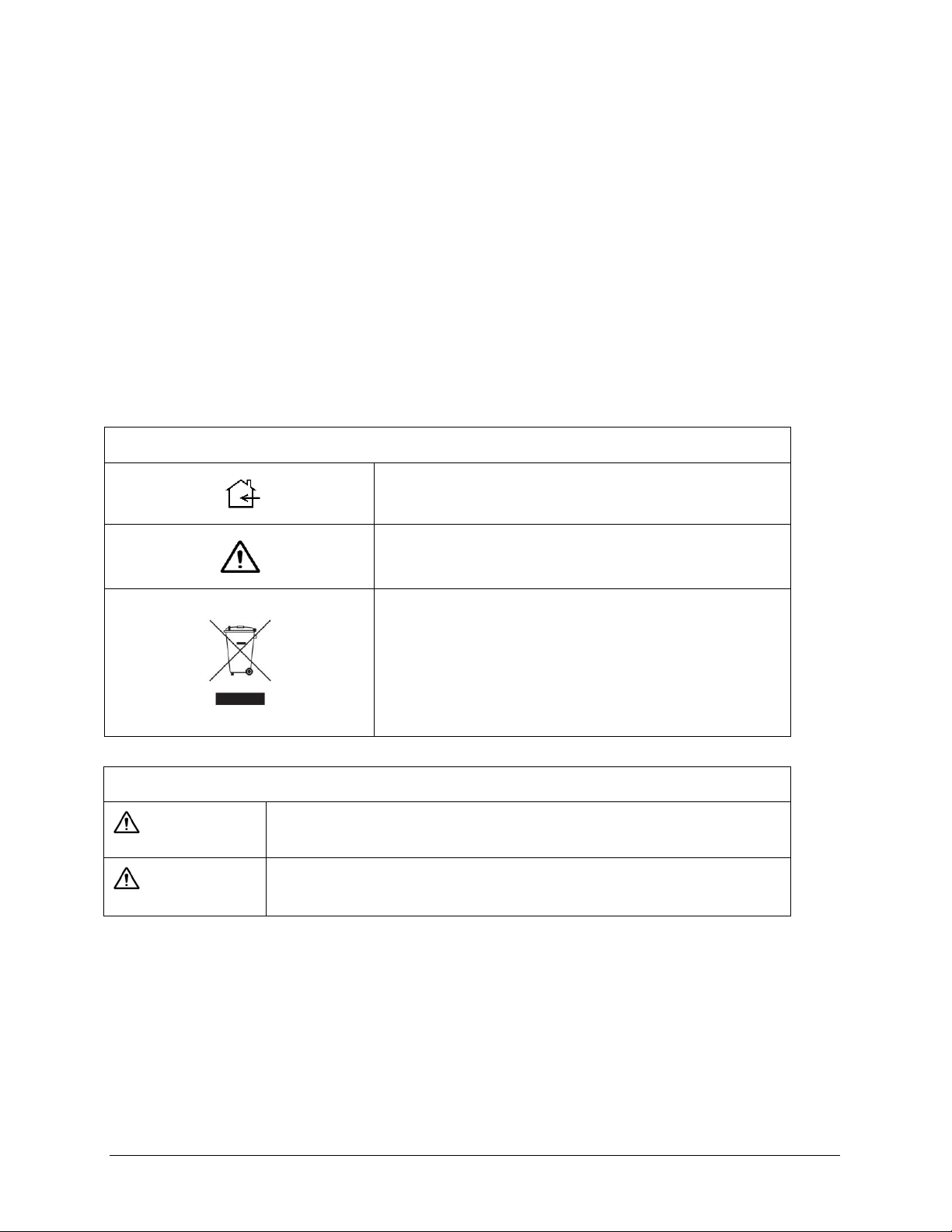
Explanation of Signal Word Consequences
WARNING:
Indicates a potentially hazardous situation, which, if not avoided, could
result in death or serious injury and/or property damage.
CAUTION:
Indicates a potentially hazardous situation, which, if not avoided, may
result in minor or moderate injury and/or property damage.
Safety Information
Read, understand, and follow all safety information contained in these instructions prior to using
any reader. Retain these instructions for future reference.
The safety labels are affixed to the underside of each reader.
Intended Use
The Gemalto Kiosk ePassport Reader optically scans passports, ID cards and other travel
documents. It also reads Contactless Integrated Circuit chips integrated into travel documents.
The reader is intended to be used in a dry indoor environment only, physically installed within a
self-service kiosk that provides a mechanical housing and limits user access to placing travel
documents on the glass imaging surface. It has not been evaluated for other uses, such as standalone desktop use or other environmental conditions.
Page 2
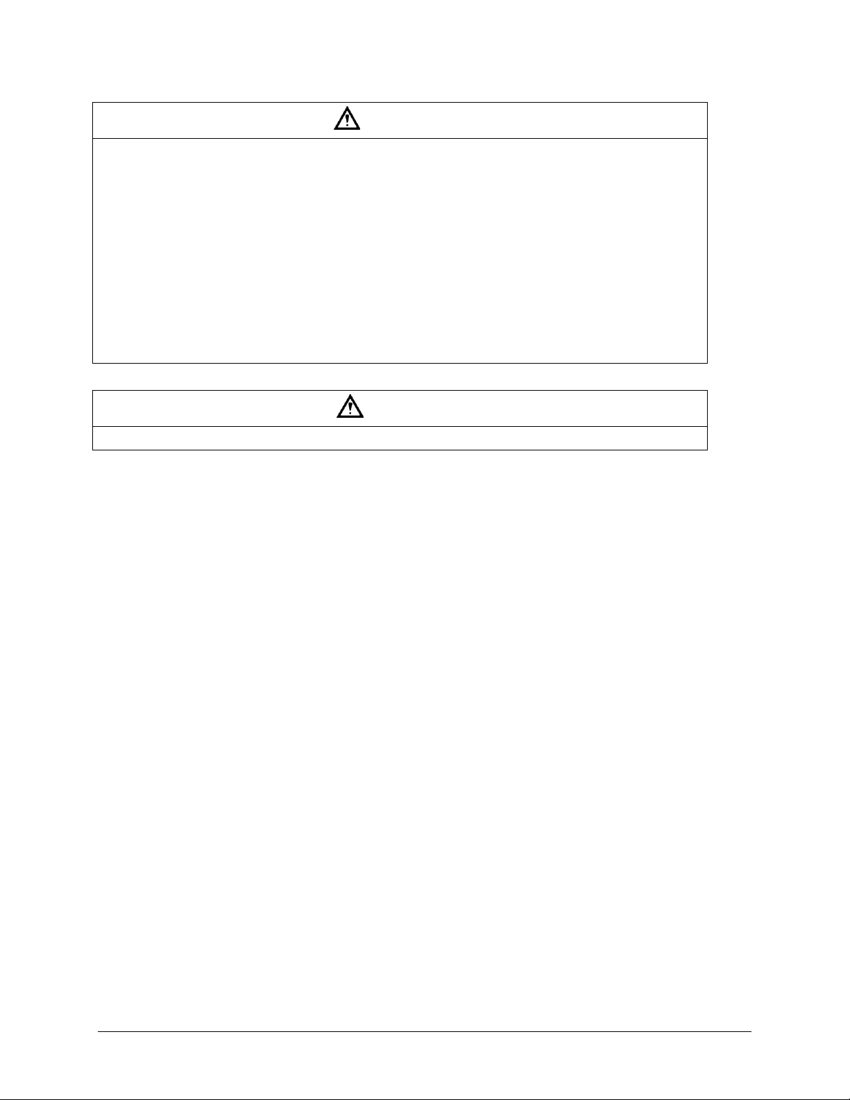
WARNING
To reduce the risk associated with hazardous voltage which, if not avoided, could result in death
or serious injury:
Do not use the reader with any AC power supply other than a Gemalto approved AC power
supply.
Do not open the reader/power supply. There are no user serviceable parts or adjustments inside.
Do not use AC power supply and/or power cord if damaged.
Product is to be serviced by Gemalto service personnel only. No user serviceable parts or
adjustments inside.
Do not modify or attempt to modify the reader and/or AC power supply.
Use only in an indoor dry location.
Do not use the product in an outdoor and/or wet environment.
CAUTION
Dispose of electronic waste in accordance with all applicable local and government regulations

Page 3
machine-readable text
cell phone/PDA detection
1D barcodes
barcode reading from cell phone/PDA
2D barcodes
customized client requirements
Extended Access Control (EAC) 1.01
specification support
document rotation detection and
processing support
contactless integrated circuit (IC) chips
(optional)
Introduction
This document describes the features and functions of the following readers:
Gemalto Kiosk Full Page Reader, model # PV35-00-17-00-01
Gemalto Kiosk ePassport Reader, model # PV35-02-17-00-01
This manual is intended to be used by kiosk hardware developers and integrators. It provides
mechanical and electrical specifications required to incorporate the readers into a kiosk as well as
guidance on the operation, troubleshooting and maintenance of the readers.
Features Overview
The Gemalto Kiosk Full Page Reader and Gemalto Kiosk ePassport Reader are a family of
intelligent optical character recognition (OCR) and full-image capture devices that provide
automated data capture from a variety of personal identification documents. They read data from
documents encoded with:
The readers capture full page document images using:
Visible color illumination
Near-infrared (B900 band) illumination
Ultra violet illumination
The readers perform optical character recognition on identity documents including those that
conform to International Civil Aviation Organization (ICAO) 9303 specifications and send data
from the document to a host computer over a Universal Serial Bus (USB) connection.
The base functionality for the different readers varies:
Gemalto Kiosk Full Page Reader
full page visible, ultra violet (UV) and infrared (IR) imaging
optical character recognition (OCR)
1D and 2D barcode reading
Gemalto Kiosk ePassport Reader
The Gemalto Kiosk ePassport Reader includes all the functionality of the Full Page model and
can also detect and read information encoded on contactless integrated circuits in passports and
ID cards. The reader:
reads ISO 14443 Type A and Type B ICs
Page 4
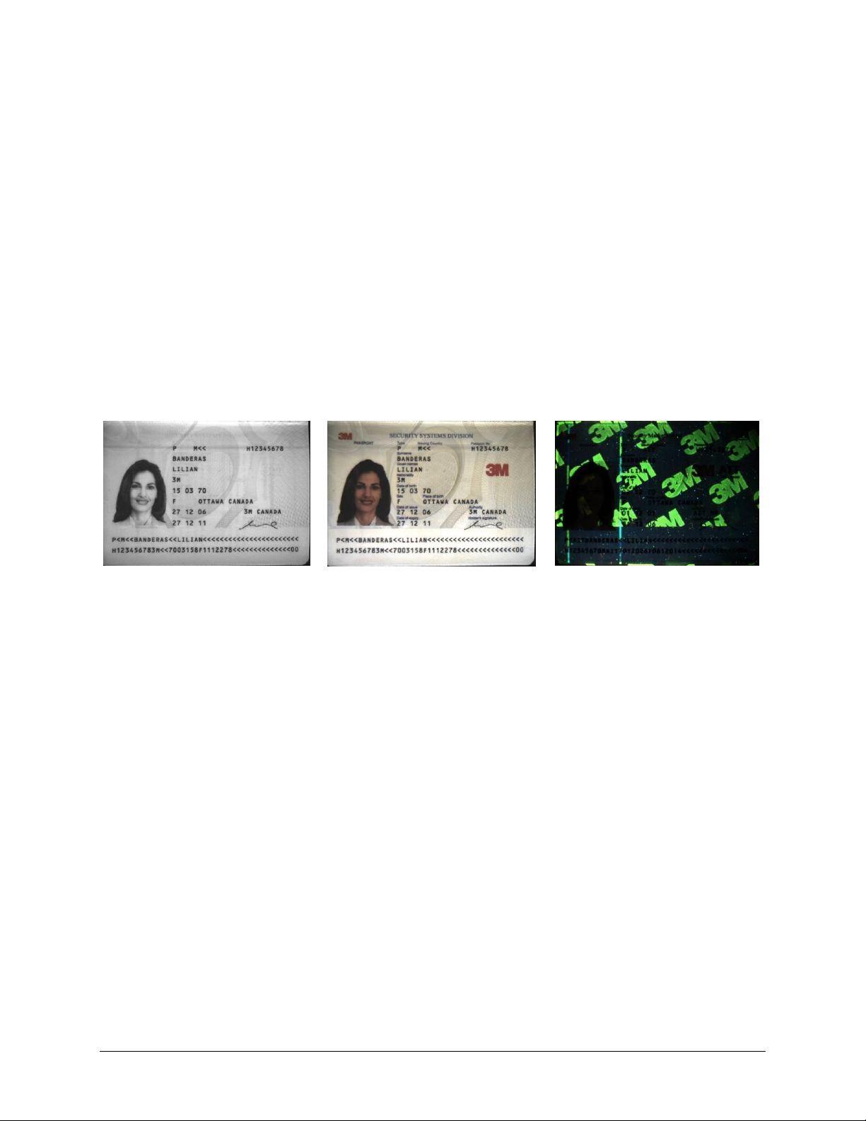
Figure 1: Infrared Image
Figure 2: Visible Image
Figure 3: Ultra Violet Image
supports reader to chip transfer rate of up to 848 Kbps when applicable (IC dependent)
provides functionality according to ICAO NTWG (New Technologies Working Group)
Technical Reports
To read passports with a chip, the reader is equipped with an antenna that completely surrounds
the document window and tray. Whether the chip is in the front or rear cover, the data page, or
any other page, the reader’s antenna will detect and read the chip. The user does not need to turn
the book around to ensure the chip is read.
The RF (radio frequency) technology used in the Gemalto Kiosk ePassport Reader is very short
range, and does not interfere with other electronic equipment such as PC monitors, wireless
communications (for example, 802.11g) or cell phones.
Document Images
The following are examples of infrared, visible and ultra violet imaging:
Related Documents
The range of applications for reading and authenticating secure documents is growing.
Particularly, with the development and deployment of ePassports and smart identity cards
authentication has become critical to security.
Gemalto has developed a collection of software development kits (SDKs) and application
programmer interfaces (APIs) to facilitate the development of verification and authentication
applications.
There are 6 documents in the SDK/API suite:
DT-01700
Gemalto Inspection and Full Page Reader Serial/USB Software Developer's
Reference
Facilitates document data capture and OCR.
Sample Function:
SavePhotoJpeg saves the jpeg data into a specific named file.
DT-01758
Optical Character Recognition Skin API Specification
Facilitates the manipulation of OCR data.
Sample Function:

Page 5
unsigned long MMM_GetOCR_TextItem returns the character string data for a specific item. For
example “@mrz_line_1” and “@mrz_line_2” are the top and bottom MRZ lines on a two-line
document.
DT-01675
Gemalto Authentication System Software Developer's Reference
Facilitates the comparison of graphical elements of scanned documents to known reference
images.
Sample Function:
RetrieveTextItem retrieves the text string for the named item.
DT-01714
Gemalto ePassport Reader SDK Developer’s Reference
Facilitates the integration of ePassports into a document handling system.
Sample Function:
Active_Authentication performs the active authentication process using the public key retrieved
from data group 15.
DT-01757
Radio Frequency Skin API Specification
Facilitates the extraction of information from ePassports.
Sample Function:
unsigned long MMM_GetRF_File reads a data group from the card embedded in the travel
document. The entire data group is returned in the data buffer.
DT-01762
Logical Data Structure Skin API Specification
Facilitates the manipulation of data found on ePassports.
Sample Function:
unsigned long MMM_LDS_ValidActiveAuthenticationSignature verifies the digital signature
returned from a radio frequency (RF) chip in response to an active authentication request.
These documents encompass the range of tools for use by programmers to develop applications
for the Gemalto Inspection Reader and Gemalto Full Page Reader family.
Some of the SDKs and APIs are complimentary, used together to perform specific tasks:
access all optical character recognition (OCR) results, images and authentication results
(Gemalto Authentication System SDK and OCR Skin API)
access a RF chip, retrieving various fields and verifying passive authentication
(Gemalto ePassport Reader SDK and RF Skin API)
Two of the kits are used alone for specific applications:
decode ICAO data groups from ePassports
(Logical Data Structure Skin API)

Page 6
retrieve USB data streams, decode and access data/images

Page 7
Product Description
The readers are self-contained devices designed to be incorporated into a self-service kiosk
terminal. The main hardware features are:
A document window and tray for placement of documents to be read
A back panel containing communication, status light emitting diode (LED) and power
connection ports
Attachment points for mounting the readers to a kiosk chassis
Document Tray and Window
The document window is a glass surface measuring 132mm x 88mm located on top of the reader.
Users place documents on the document tray, imaging side down, and slide them to the back of
the document window to scan them. Guides on the document tray help align the document and
keep it pressed onto the glass window. The document window is slightly larger than ICAO 9303
requirements to accommodate oversized documents.
Keep the document tray and window clean to ensure optimum operation of the reader. See
Cleaning on page 22 for more information.
Figure 4: Document Tray and Window

Page 8
Ready (Green)
The reader is ready to scan a document (when connected to the host
application).
Busy (Amber)
The reader is scanning a document and processing the data.
OK (Green)
A known document type was presented and processing was successful.
Error (Red)
The document is of an unknown type or did not process properly.
Back Panel
The back panel features the USB communication ports, status light emitting diodes (LEDs), a
connector to drive a secondary set of status LEDs and a power supply connector.
Figure 5: Back Panel Ports
USB Ports
Communication to and from the host PC is via USB 2.0. The USB host interface is a standard
Type B connector. The reader does not draw any power from the host.
A built-in USB hub and two auxilliary USB 2.0 Type A connectors allow you to connect
additional USB peripherals such as a mouse, keyboard, etc. The two USB peripheral connectors
are capable of supplying +5V DC at a total of 500mA to the peripherals (e.g. 500mA to a single
peripheral, 250mA to each of two peripherals, etc.).
Status Indicator LED’s
The status LEDs are intended to assist a technician to install and debug the reader, and indicate
the reader status and the result of scanning a document. They are not visible by a user.
Table 1: Indicator LEDs

Page 9
A five-pin header is provided to drive a remotely-located status LED display on the kiosk, or to
allow the kiosk hardware to monitor the status of the reader. The reader connector is designed to
mate with Molex part number 0874390600 housing and 87421 crimp terminals. The remote
status LED’s are assumed to have a common anode at +3.3V. The reader will pull connector pins
to ground through 200-ohm resistors, supplying approximately 7.5mA per LED. Pin assignment
of this connector is shown in the following figure.
Figure 6: Status LED Connector
Power Connector
The reader must be connected to a Underwriters Laboratory (UL)-Listed DC power supply
capable of providing +12V DC at 1.1A. The connector pinouts are shown in the following figure.
Figure 7: Power Supply Connector
Mounting Points
The readers contain eight M4 threaded mounting bosses, two on each side and four on the
bottom, as shown in the following figure. The preferred mounting points are on the bottom. If the
side mounting points are used, care must be taken in the design of the kiosk mounting surfaces to
ensure that tensile stress is not placed on the reader chassis. The M4 hardware should protrude
into the reader chassis no more than 8mm.
At the factory, all eight bosses are filled with threaded plastic inserts to prevent dust entry into
the enclosure.

Page 10
Figure 8: Mounting - Mechanical Detail

Page 11
Installing the Hardware
Before installing the hardware, consider the following:
proper procedure for unpacking the reader
proper kiosk design
Unpacking the Reader
Each reader package consists of:
1 reader
1 test card
1 USB communication cable
Power supply and line cord
1 Scotch-Brite™ Microfiber Cleaning Cloth
1. Remove the contents from the box and separate the components from the packing
material.
2. Verify that all the parts described have been received. If any parts are missing, contact
Gemalto Global Technical Services (GTS).
For more information, see Appendix D: Customer Service on page 29.
3. Store the packaging in the event that the reader may require reshipment to Gemalto for
maintenance.
Note: Allow the reader to come to room temperature for a minimum two hours
before operation, if it has been stored below room temperature.
Kiosk Design Considerations
The reader is designed to be mounted behind the kiosk front panel with only the document tray
protruding. The front panel must provide an opening to allow users to insert their documents and
hold them flat on the document glass for scanning. The opening should form a box, open at the
front and closed at the top, sides and back.
To better illustrate this, a typical kiosk concept is shown in the following figures. It is
recommended that the material forming the document cavity and the front fascia around the
reader be non-metallic (e.g. Polycarbonate) to avoid affecting the RF performance. This is
illustrated in red in the following figures. The cutaway view shows the reader mounted to the
bottom surface of the kiosk chassis, with the plastic insert forming the document cavity. The
document cavity must allow sufficient clearance for a user’s hand to hold the document down on
the glass.
To assist in the mechanical design, 3D CAD models of the reader are available in all popular
formats. Contact your sales representative or GTS for details.

Page 12
Figure 9: Kiosk Concept - Front View
Figure 10: Kiosk Concept - Cutaway View
The reader is designed to be held in place using four M4 machine screws. See the previous
section for detailed mechanical dimensions of the reader and its threaded mounting points.
When designing a kiosk to accommodate the reader, consider the following factors:
Attach the reader using the bottom attachment points, if possible
In ePassport models, keep metallic surfaces away from the document tray and document
glass. These areas contain the radio frequency identification (RFID) antenna, and RF
reading can be disrupted by the presence of metal in the RF field

Page 13
In ePassport models, the front fascia should be plastic or a non-metallic material
In ePassport models, do not allow a metallic surface under and parallel to the document
tray
Allow sufficient clearance above the document window for the user to hold the document
down on the document window
The document window must be shielded as much as possible from direct lighting
(reference mechanical drawing DT-01823), and any surfaces directly above the document
window must be matte black. Failure to observe this may cause unreliable document
detection.
Figure 11: Mounting - Recommended
Figure 12: Mounting - Not Recommended
Note: The reader should be inclined 5° to 10° to prevent liquid from entering the kiosk and to
discourage its use as a shelf.
Connecting the Power Supply
The reader is designed to be powered from a switched, UL-listed power source supplied with the
kiosk and terminating in a suitable DIN connector. The reader is supplied with a power cable and
power supply but does not have a power switch.
Connect the DIN connector from the power supply to the power connector at the rear of the
reader, and secure or tie-off the cable as required.
Note: If you choose to use your own power supply, it must be a UL-listed device. Contact your
sales representative or Gemalto Global Technical Services (GTS) for details.
Connecting to the Host System
The reader is supplied with a 2-meter USB A-B communication cable.

Page 14
1. Insert the USB connector of the supplied cable into a USB port on the host system.
2. Insert the USB connector of the supplied cable into the USB port, located on the back
panel of the reader.
3. Secure or tie-off the cable as required.

Page 15
Installing the software
The reader package contains a Quick Start Guide with links to an online site to download the
software components and documentation, consisting of:
Gemalto software and SDK
Reader and software documentation
Required drivers
Additional SDKs based on the reader model
To install the reader software:
1. Download the latest SDK software from the provided link. Click on the Gemalto Page
Reader SDK x.x.x Setup.exe link and save the exe file to a known location on the host PC
(for example, the desktop).
2. Run the downloaded .exe file.
The installation wizard starts.
3. Click Next to proceed with the installation.
The software license is displayed.
4. If you accept the License Agreement, select I accept the terms of this license
agreement.
5. Click Next to proceed with the installation.
The Installation Type dialogue is displayed.

Page 16
6. Select whether you want the SDK to be visible to all users or just yourself.
7. Click Next to proceed with the installation.
8. The Select Components screen is displayed. Click Typical.
9. Select the shortcuts that the installation should create.
10. Click Next.
The Ready To Install window is displayed.

Page 17
11. Click Install to proceed with the installation.
The wizard installs the software.
A separate installation for the reader device drivers is displayed.
12. Review the installation notes for any specific instructions.
13. Click Next to proceed with the installation.
The device drivers are installed. After the driver installation the final installation page will be
displayed.
14. Click Finish.
The installation of the software and drivers is complete.

Page 18
LED Behaviour
Meaning
The Ready LED flashes rapidly
No USB connection detected
The Ready and Error LEDs flash rapidly
USB 1.1 connection detected
Verifying the USB Driver Installation
1. Right-click on My Computer and click on Properties.
The System Properties window opens.
Figure 13: System Properties window
2. Click on the Hardware tab, then on Device Manager.
The Device Manager window opens.
3. Expand (click on the plus sign) the entry called Smart Card Readers.
4. Verify that there are entries for the USB SmartCard and USB Contactless Readers
(ePassport option only).
Note: If you cannot verify that the drivers have been properly installed, turn the reader
off and back on and try the installation again. If verification still fails, contact
Gemalto Global Technical Services (GTS).
For more information, see Appendix D: Customer Service on page 29.
Power-up Self Test
A power-up self-test occurs automatically when the reader powers up. If the reader is installed
correctly and is operational, the status LEDs perform the following sequence:
All LEDs come ON briefly at initial power-up.
After several seconds the green LED (READY) remains ON, and all other LEDs go OFF.
The LEDs may also indicate the following common communication errors:
Note: The reader will not transfer document images over a USB 1.1 host connection.
However, RFID chip reading (ePassport option only) and any USB 1.1
peripherals attached to the reader will function over a USB 1.1 host connection.

Page 19
Testing Reading and Communication
This test determines if the reader is functioning properly.
1. Start the application Page Reader Expo from the shortcut created during software
installation.
2. Select a scheme that matches your reader. If you are unsure, select the “ePassport and
Images” scheme.
3. Click Select.
4. Verify that the green LED (READY) is on and the test application indicates Ready to
Scan. (The reader is ready to accept documents).
5. Select the test card DS-00031 (ePassport) or DS-00034 (Full Page) supplied with the
reader.
Note: Readers with the ePassport option are supplied with test card DS-00031
containing OCR data as well as a programmed contactless chip. Readers
without the ePassport option are supplied with test card DS-00034 containing
only OCR data.
6. Place the test card face down on the document tray.
Note: For best reading results, align the document with the left guide.
7. Push the card to the back of the document window until it stops.
Note: Do not move the document during the scanning process.
8. Observe the LEDs during the scanning procedure.
The READY LED turns off and the amber LED (BUSY) turns on.
The amber LED (BUSY) remains on while the reader scans and processes the data.
The green LED (OK) turns on, indicating a successful read.
The READY LED turns on, indicating that the reader is ready to scan another
document.
The data from the test card is sent to the host computer and the results displayed on the PC
screen.

Page 20
Figure 14: Successful RFID Chip Reading
Reading Procedure
This section describes the proper document placement for travel document booklets.
Note: Hold the document open as you place it into the document slot.
1. Place the booklet on the document platform.
Figure 15: Reading Procedure - Document Placement
Note: You may want to use two hands to insert the document into the reader.

Page 21
Travel document
fully inserted
Inspection results
displayed on screen
Figure 16: Reading Procedure - Document Insertion
2. Push the booklet into the slot until the leading edge is all the way to the back.
When the document reaches its proper position, the reader will automatically start
scanning the document.
Note: Make sure the document lies flat against the document platform during
reading.
3. Watch the kiosk screen to ensure the document passes inspection.
Figure 17: Reading Procedure - Inspection Results

Page 22
Maintenance
The readers have no user-serviceable parts but the glass surface must be cleaned on a regular
basis. For extensive repairs, return the reader to a Gemalto service depot. See Appendix D:
Customer Service on page 29
Cleaning
Clean the reader regularly to ensure proper performance.
Note: Use a safe cloth that will not damage glass, such as the Scotch-Brite™ Microfiber
Cleaning Cloth (provided). To reorder cleaning cloths (part number 70071086394),
contact Gemalto Global Technical Services (GTS).
See Appendix D: Customer Service on page 29 for more information.
1. Clean the document window with a clean cloth.
For dirt, use a mild glass cleaner or a lightly dampened cloth (water).
Note: Do not use abrasive cleaners or solvents. These may scratch the glass or
damage the plastic.
Do not used compressed air, as this may force debris into the reader.
2. Verify that there are no streaks or smudge spots remaining on the document window.
3. If required, clean the body of the reader with a lightly dampened cloth (water).

Page 23
Dimensions
Length 29.2 cm (11.5”)
Width 16.9 cm (6.7”)Height 9.9 cm (3.9”)
Weight
1.1 kg (40 ounces)
Input voltage
12 V DC
Power consumption
3 watts (not including USB peripherals)
Connector
4 pin Mini-DIN
Temperature
Operating
0 – 40°C (32 – 104°F)
Storage
-20 – 50°C (-4 – 122°F)
Humidity
Operating
20 – 80% non-condensing
Storage
5 – 95% non-condensing
Connection
Interface
USB 2.0, 480 Mbit/s “High Speed”
Host USB Power
Reader draws no power from host USB connector
USB connector
USB B (host), USB A x 2 (peripherals)
USB cable length
2.00 m (79”)
Aux. USB power
5V DC, 500mA total (both ports combined)
RF Chip
ISO 14443-2,3,4
Device Safety
Appendix A: Specifications
Figure 18: Physical Dimensions
Table 2: Physical Specifications
Table 3: Electrical Specifications
Table 4: Environmental Specifications
Table 5: Communication Interfaces and Protocols
Table 6: Regulatory Information

Page 24
USA
UL60950
EEA
EN60950
RoW
IEC60950
EMC – emissions
USA
FCC Part 15, sub-part B, Class A, sub-part 15.225
Canada
ICES-003, RSS-210
EEA
EN55022 Class B
Australia
AS/NZS 3548
EMC – immunity
EEA
EN55024
EMC
EMC
ESTI EN 301 489-1 V1.6.1 (2005-09)
EMC
ESTI EN 301 489-3 V1.4.1 (2002-08)
EMC
ESTI EN 300 330-1 V1.5.1 (2006-04)
EMC
ESTI EN 300 330-2 V1.3.1 (2006-04)
EN50364
Limitation of human exposure to electromagnetic fields from
devices operating in the frequency range 0 Hz to 10 GHz, used in
electronic article surveillance (EAS), radio frequency identification
(RFID) and similar applications.

Page 25
Symptom
Possible Causes
Actions
The LEDs do not
come on during
power up.
There is no power to
the reader.
Verify the kiosk power source.
Verify that the power cable is connected to the
power supply port located on the back panel.
Verify that the power cable pinouts are correct.
The unit is damaged.
Follow the procedure outlined in Appendix D:
Customer Service on page 29.
The reader is not
communicating
with host PC
system.
The cable is not
properly connected or
USB drivers are not
properly installed.
Verify that the USB cable is connected to the
host.
Verify that the USB driver is installed, page 18.
Verify that only one reader is connected to the
host system.
Follow the procedure outlined in Chipset
Updating on page 28.
The Error LED
illuminates when a
document is
scanned.
The document is nonmachine readable.
This is a normal condition when there is no
machine readable data and only the image is
captured from the document.
The document is poorly
printed.
The reader is designed to read documents
that are poorly printed. However, some
documents are of such poor quality that the
reader will not be able to process the OCR
data.
High ambient light.
Ensure kiosk orientation is such that bright
light does not fall directly on the document
window.
The unit is not
configured to read the
document being
scanned.
The document may not conform to one of the
known document templates contained within
the software.
Contact GTS.
The document is not
orientated correctly on
the scanning window.
Ensure document is properly positioned as
described in Testing Reading and
Communication on page 19.
The document is faulty
or non-compliant.
Verify the document conforms to ICAO 9303
or OCR B font requirements.
Appendix B: Troubleshooting
Use this table to identify and correct common issues encountered when using the reader. If a
problem cannot be solved using this table, contact Gemalto Global Technical Services (GTS).
See Appendix D: Customer Service on page 29.
Table 7: Troubleshooting Cases

Page 26
Symptom
Possible Causes
Actions
The Ready LED is
continuously
blinking.
The USB cable is not
connected.
Verify that the cable is installed and the host
PC is ON.
The system has no
USB 2.0 capability.
Verify that the USB 2.0 hardware is ready.
Refer to Appendix C "Check for High speed
USB".
The Sales Demo
application is not
working.
The software is installed
incorrectly.
The application may already be running. Verify
that only one copy of the application is
running.
Remove the existing application & re-install
software. For more information see the
Software Installation section.
You do not have PC
Administrative rights to
install the software.
Consult with your IT support representative.
The LEDs do not
change after
reading an RF
chip.
Normal
This is a normal condition. RF status is
displayed only on the host screen.
The reader
becomes
unresponsive.
Depending on the
implementation of the
PC application and the
volume of USB traffic,
AC line transients may
cause unrecoverable
errors in USB data
transmissions.
Restart the PC application or disconnect and
reconnect the USB plug from either the PC or
the reader.

Page 27
Appendix C: Check for High Speed USB 2.0
The reader is a USB 2.0 device that requires a Microsoft® Windows® 2000-SP4, Windows®
XP or Windows® Vista operating system.
Note: The reader will not function in a USB 1.1 environment. Make sure a commercially-
available USB 2.0 card is installed in your PC. For problems with your operating system,
consult with your local IT representative. For other problems contact Gemalto Global
Technical Services (GTS). See Appendix D: Customer Service on page 29.
Windows® 2000
1. In Windows® 2000, right-click My Computer and select Properties.
Figure 19: System Properties window
2. Locate the version number on the General tab and verify that Service Pack 4 or greater
has been installed.
3. Right-click My Computer and select Manage.
4. Click on Device Manager in the Tree list.
5. Under Universal Serial Bus controllers locate USB 2.0 Root Hub.
Figure 20: Windows® 2000 SP4 Computer Management window
6. If your Device Manager displays USB 2.0 Root Hub, the system has high speed USB
2.0 capability.

Page 28
Windows® XP
1. In Windows® XP, right-click My Computer and select Manage. Click on Device
Manager in the Tree list.
2. Under Universal Serial Bus controllers locate an “Enhanced” entry.
Figure 21: Windows® XP Computer Management window
3. If your Device Manager displays Enhanced USB Host Controller, the system has high
speed USB 2.0 capability.
Chipset Updating
The Check for High Speed USB 2.0 process determines if the PC has the correct hardware.
Chipset updating ensures that the PC also has the correct driver software for that hardware.
The program chipid.exe is used to determine your chipset.
It is available in the install directory on your system following installation.
If the workstation uses the Intel USB chipset, follow this link to locate the latest updates:
http://downloadfinder.intel.com/scripts-df-external/Support_Intel.aspx.

Page 29
The Americas
1545 Carling Ave. Suite 700
Ottawa, ON K1Z 8P9
Telephone: +1 613 221-4948
Europe, Middle East and Africa
35 Harbour Exchange Square
London, E14 9GE
Telephone: +44 (0) 203 435 5786
Asia, Pacific and Australia
12 Ayer Rajah Crescent
Singapore 139941
Telephone: +65 6317 3427
Appendix D: Customer Service
If you cannot solve the problem after following the instructions on page 39, contact Gemalto’s
Global Technical Services (GTS).
Before contacting GTS
Be prepared to provide the information required to properly diagnose the problem:
A detailed description of the problem
A detailed description of the actions taken to correct the problem
The serial number of the reader (located on the reader’s bottom panel)
Contacting GTS
Once you have the above information, contact GTS via one of the following methods:

Page 30
Returning the reader for maintenance
In the event of a suspected problem with Gemalto equipment, please use the following
procedure.
To return a reader for maintenance:
1. Diagnose – The system manager will determine that there is an actual fault with the
equipment which cannot be corrected by following the procedures in this document or
with local in-house knowledge.
2. Initiate Call – The system manager should contact Gemalto GTS via telephone, fax, or
email. GTS will request a detailed description of the problem along with the serial number
of the unit. It is the customer’s responsibility to include or have on hand all
pertinent information.
3. Response/Call Back – A GTS representative will discuss with the system manager to
determine the problem. If the problem can be corrected locally by the system manager
with the guidance of the GTS representative, no further action will be required.
4. Return Authorization – If the problem cannot be corrected via telephone assistance, the
GTS representative will issue a Return Materials Authorization (RMA) number. The RMA
number will be used to track the failed reader, along with verification of the location of the
service depot to where it should be sent.
5. Return – The end user system manager will carefully disconnect the defective equipment.
The reader should ideally be packaged in its original packing box. If not, a suitable box
with sufficient packing material should be used to minimize damage during transit.
The RMA number should be prominently displayed on the shipping container in
which the reader is being returned. This reference number will ensure prompt
processing of the equipment once it arrives at Gemalto.
The CUSTOMER is responsible for insurance coverage on the reader in case of loss
or damage during transit to Gemalto. The reader should be returned to the Gemalto
designated service depot.
6. Shipping Instructions – Four copies of a commercial invoice, a packing slip, a pro forma
invoice, or the following information, typed on letterhead, must be sent with the reader:
Description of equipment, including serial numbers
Quantity
Value and Country of Origin
Exporter (customer's company)
Consignee (Gemalto)
Please affix the instructions to the outside of the container.
7. Repair – When the defective equipment is received at the service depot, the reader will be
repaired, tested and returned to the CUSTOMER’S central depot. Subject to unavoidable
delays, this effort should not exceed 10 business days (exclusive of shipping time).
 Loading...