

Page 1
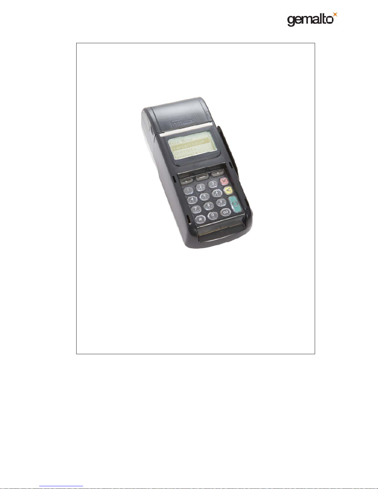
E-Payment MagIC
3
M-series Handset - MAINTENANCE MANUAL
INTRODUCTION
Ref: 22000-02-MAN-I-08010 August 2009 1/35
Copyright Gemalto – 2008 No disclosure to a third party without prior written consent of Gemalto
Point of Sales Terminals
MagIC
3
M-series Handset
MAINTENANCE MANUAL
Version 2.0 - August 2009
Page 2

E-Payment MagIC
3
M-series Handset - MAINTENANCE MANUAL
INTRODUCTION
Ref: 22000-02-MAN-I-08010 August 2009 2/35
Copyright Gemalto – 2008 No disclosure to a third party without prior written consent of Gemalto
COPYRIGHT AND PROPRIETARY LEGENDS
These materials contain confidential and proprietary information in the nature of, for
example, trade secrets and know-how, and are not to be distributed or divulged to third
parties, or duplicated in whole or in part without prior written permission from Gemalto E-
Payment, and are subject to use, copying, and disclosure restrictions contained in a
agreement with Gemalto E-Payment.
These materials are to be used only for the intended purpose agreed upon in the related
contract with Gemalto E-Payment. IN NO EVENT SHALL GEMALTO E-PAYMENT BE
LIABLE FOR SPECIAL, INDIRECT, OR CONSEQUENTIAL DAMAGES IN CONNECTION
WITH OR ARISING FROM THE USE OF THIS DOCUMENT OR ANY PROGRAMS
CONTAINED HEREIN. GEMALTO E-PAYMENT EXPRESSLY DISCLAIMS ANY
WARRANTY OF MERCHANTABILITY OR FITNESS FOR A PARTICULAR PURPOSE IN
RELATION TO THIS DOCUMENT OR ANY PROGRAMS CONTAINED HEREIN.
Copyright (c) 2008 by Gemalto
All rights reserved.
Page 3

E-Payment MagIC
3
M-series Handset - MAINTENANCE MANUAL
INTRODUCTION
Ref: 22000-02-MAN-I-08010 August 2009 3/35
Copyright Gemalto – 2008 No disclosure to a third party without prior written consent of Gemalto
MODIFICATION SHEET
Date Version Modifications
Aug 2008 1.0 Draft
Oct 2008 1.1 Release
Oct 2008 1.2 Updated III- MI16 Elastomeric replacement.
August 2009 2.0
Updated
I-2
Updated
II-2.12. SECURITY ALERT procedure.
Added
II-3.0. SECURITY ALERT SP status register.
Updated
III- MI5, MI7, MI9, MI11, MI15.
Updated LITHIUM_BAT voltage threshold replacement
Page 4

E-Payment MagIC
3
M-series Handset - MAINTENANCE MANUAL
INTRODUCTION
Ref: 22000-02-MAN-I-08010 August 2009 4/35
Copyright Gemalto – 2008 No disclosure to a third party without prior written consent of Gemalto
Table of contents
INTRODUCTION................................................................................................................... 5
1. Scope.............................................................................................................................5
1.1 References.............................................................................................................. 5
1.2 MagIC3 Diag software ............................................................................................. 5
1.3 Abbreviations used .................................................................................................5
I) - DESCRIPTION ................................................................................................................6
2. System Product Architecture design .............................................................................. 6
2.1 Technical overview .................................................................................................6
2.2 Physical Architecture ..............................................................................................8
3. Software Architecture...................................................................................................16
II) - TROUBLESHOOTING.................................................................................................. 18
1. Introduction ..................................................................................................................18
1.1 Methodology .........................................................................................................18
1.2 Safety regulation ................................................................................................... 18
1.3 Special tools and test equipment ..........................................................................18
1.4 Procedure .............................................................................................................19
2. Troubleshooting Instructions ........................................................................................ 20
2.1 BATTERY-PACK failure........................................................................................ 20
2.2 POWER SUPPLY failure.......................................................................................21
2.3 DISPLAY failure ....................................................................................................22
2.4 KEYBOARD failure ...............................................................................................22
2.5 PRINTER failure ...................................................................................................23
2.6 MAGNETIC READER failure ................................................................................24
2.7 CUSTOMER SMART CARD READER failure ...................................................... 25
2.8 SAM READER (SIM-sized) failure ........................................................................ 25
2.9 GSM INTERFACE failure...................................................................................... 26
2.10 USB failure............................................................................................................ 27
2.11 BASE CONTACT INTERFACE failure .................................................................. 27
2.12 SECURITY ALERT / LITHIUM BATTERY failure.................................................. 28
3. SECURITY ALERT – How to interprete SP Status information.................................... 31
3.1 SP STATUS ticket information .............................................................................. 32
3.2 UKSR/SECIRQ values meanings .........................................................................33
3.3 Interpreting UKSR/SECIRQ values....................................................................... 33
III) - MAINTENANCE …………………………………………………………..……………. RI[01]
Page 5

E-Payment MagIC
3
M-series Handset - MAINTENANCE MANUAL
INTRODUCTION
Ref: 22000-02-MAN-I-08010 August 2009 5/35
Copyright Gemalto – 2008 No disclosure to a third party without prior written consent of Gemalto
INTRODUCTION
1. Scope
This document relates to the MagIC3 M-series Handset. The aim of this manual is to give
necessary technical information and procedures to carry out all maintenance activities
needed during the life span of the MagIC3 M-series Handset.
This guide is divided in 3 parts:
• I) Description, consisting in a detailed description of the terminal and its equipment.
• II) Troubleshooting, explaining how to find the root cause of failures.
• III) Maintenance, containing replacement procedures for all parts that can be
exchanged during Maintenance level 2 operation.
It mainly makes reference to the Maintenance software MagIC3-Diag RI[02].
1.1 References
RI[01] : 22000-02-MAN-I-08011 Part III - MAINTENANCE
RI[02] : 15200-00-MAN-S-07001 Maintenance software, MagIC3-Diag User Manual
1.2 MagIC3 Diag software
You have to use MagIC3 Diag version 1.5 minimum to test M-series. This software tool
is available on the MPO site.
1.3 Abbreviations used
AM Application Manager
MMS MagIC Management System
MP Main Processor
OS Operating System
PCB Printed Circuit Board
POS Point Of Sale
SAM Security Application Module
SIM Subscriber Identification Module
SMD Surface Mounted Device
SP Secure Processor
TMS Terminal Management System
Page 6

E-Payment MagIC
3
M-series Handset - MAINTENANCE MANUAL
Chapter 1 : DESCRIPTION
Ref: 22000-02-MAN-I-08010 August 2009 Ch.1 - 6/35
Copyright Gemalto – 2008 No disclosure to a third party without prior written consent of Gemalto
I) - DESCRIPTION
2. System Product Architecture design
2.1 Technical overview
The M-series Handset product is based on dual micro-processor architecture, the secure
microcontroller to manage security purposes, the main processor as application manager.
The Handset architecture is mainly made of 3 electronic boards:
• The Keyboard PCB supports the keypad rubber membrane, the Smart card reader,
the display connectors and the SP (Secure Processor). Lithium battery backup is
located on this board too. This PCB is connected to the Main board through 30-pin
board-to-board connector.
• The Main PCB supports the MP (Main Processor), memories (RAM, Flash,
EEPROM), Power/Charge manager and connectors for devices (SAM readers, mag
stripe rdr, printer, radio module, battery pack, external contacts with the Base,
USBA & power supply jack).
• A secure box, mades of PCB, that covers sensitive signals/components of the
keyboard board.
The Handset is made of following devices:
• 32-bit RISC core ARM7, as SP (Secure Processor) ;
• 32-bit RISC core ARM9, as MP (Main Processor) ;
• 4 / 8 Mb Flash, 16 / 32 Mb SDRAM, 1024-bit EEPROM ;
• Lithium battery to back-up sensitive data and triggering data stored in SP ;
• Magnetic stripe reader ;
• Customer smart card reader ;
• 2 accessible SIM-sized readers ;
• 1 accessible SIM-sized reader dedicated to GSM SIM ;
• GPRS radio module ;
• 128x64 graphic display with backlight, no icons ;
• Keypad with backlight ;
• Buzzer ;
• Thermal printer ;
• 1 USB host ;
• Power supply input.
Page 7
E-Payment MagIC
3
M-series Handset - MAINTENANCE MANUAL
Chapter 1 : DESCRIPTION
Ref: 22000-02-MAN-I-08010 August 2009 Ch.1 - 7/35
Copyright Gemalto – 2008 No disclosure to a third party without prior written consent of Gemalto
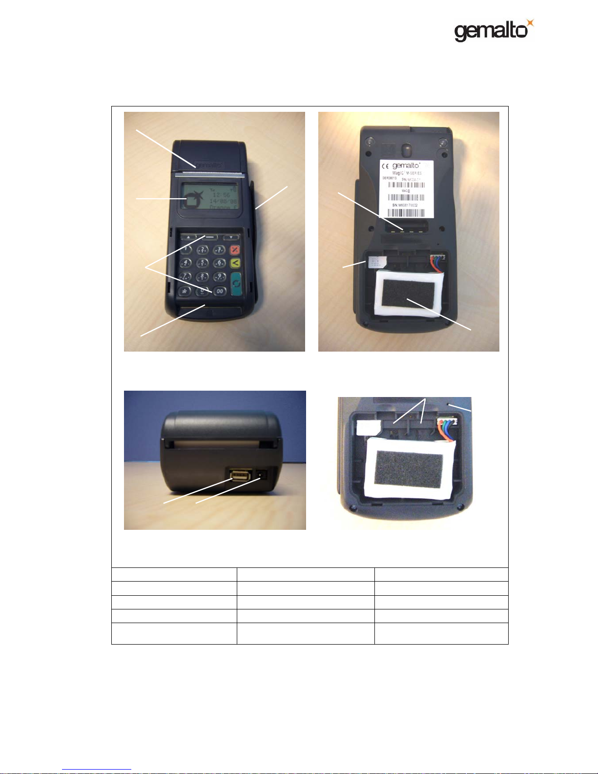
1. Printer 6. Contacts with Base 11. USB Device
2. Display 7. SIM-sized reader for GSM 12. Power Supply
3. Keyboard 8. Battery pack
4. Smart Card Reader 9. Reset button
5. Magnetic Stripe Reader 10. 2 x SIM-sized readers for
application purpose.
2
3
5
1
4
6
7
11
10
8
12
9
Page 8
E-Payment MagIC
3
M-series Handset - MAINTENANCE MANUAL
Chapter 1 : DESCRIPTION
Ref: 22000-02-MAN-I-08010 August 2009 Ch.1 - 8/35
Copyright Gemalto – 2008 No disclosure to a third party without prior written consent of Gemalto
2.2 Physical Architecture
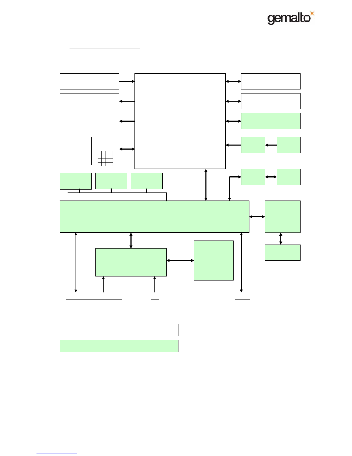
2.2.1 Block diagram
Main Processor
AT91SAM9260
Radio
Module
MC55/56
Thermal
printer
Driver
Secure Processor
AT91SO101
ROM: 32 kbytes
EEPROM: 256 kbytes
RAM: 100 kbytes
h/w TRNG, TDES, RSA accelerator
Intrusion sensors,
Protection against SPA/DPA attacks
Environment protection systems (Voltage, frequency
temperature, UV)
SIM1 to SIM2
smart card readers
Customer
smart card reader
Intrusion switches
& mesh sensors
Battery backup
Graphic display
Graphic display
Buzzer
Keyboard
EEPROM
FLASH
EPROM
SDRAM
Magnetic
stripe
Driver
SIM GSM
Li-ion
Battery pack
/
Fuel gauge
Charge management
/
Power management
Com Base Vin Base Vin USB-h < In/Out
Base contacts jack usb-a < connectors
Element located or linked with Keyboard pcb
Element located or linked with Main pcb
Page 9

E-Payment MagIC
3
M-series Handset - MAINTENANCE MANUAL
Chapter 1 : DESCRIPTION
Ref: 22000-02-MAN-I-08010 August 2009 Ch.1 - 9/35
Copyright Gemalto – 2008 No disclosure to a third party without prior written consent of Gemalto
2.2.2 The AT91SO101, the Secure Processor
The AT91SO101 is a single package solution in BGA256 embedding two chips, the
AT91SO100 and the AT83C26
The AT91SO100 is a 32-bit microcontroller based on the ARM RISC architecture
(ARM7TDMI code compatible) with embedded EEPROM, RAM and peripheral functions. It
achieves throughputs close to 1 MIPS per Mhz.
The AT83C26 is a multiple Smart Card Reader interface. Combined to the AT91SO100, it
makes a fully compatible solution with ISO7816, EMV2000 level1 standards.
Below are the main features of the AT91SO101:
• 256 Kb EEPROM, 96 Kb RAM, 4 Kb crypto RAM, 32 Kb ROM
• RTC, System timers, Communication ports
• 1x ISO7816 controller
• 1x ISO7816 multiplexed to address up to 4 SAM in our application
• DES3, AES, SHA, crypto multiplier (RSA, DSA, key generation, ECC)
• True random number generator
Security features :
• 256 bits for key storage (battery backup)
• Dedicated hardware for protection against SPA/DPA attacks
• Active shield, intrusions sensors (mesh & switches)
• Environmental protection (voltage, frequency, temperature)
• Secure memory management
2.2.3 The AT91SAM9260, as Main Processor
The AT91RM9260 is a complete system-on-chip built around the ARM926EJ-S core.
The AT91RM9260 operating frequency can go up to 200 MHz.
The ARM926EJ-S, an ARM9 32-bits RISC processor with :
• Mode Thumb
• 8 Kb Data cache, 8 Kb instruction cache
• MMU to provide access permission checks for instruction and data
• A set of system peripherals & interfaces ; timers, RTC, interrupt controller, I/O, USB,
etc…
• Embedded memories (8 Kb SRAM, 32 Kb ROM)
Page 10

E-Payment MagIC
3
M-series Handset - MAINTENANCE MANUAL
Chapter 1 : DESCRIPTION
Ref: 22000-02-MAN-I-08010 August 2009 Ch.1 - 10/35
Copyright Gemalto – 2008 No disclosure to a third party without prior written consent of Gemalto
2.2.4 External Memory
2.2.4.1 FLASH
The Flash (8 Mb NOR-Flash) contains boot and compressed executable files as Linux, AM,
Applications, … The executable files are uncompressed and copied in SDRAM for
execution. Flash can be compared to the disk of your PC, a kind of Flash-disk.
2.2.4.2 SDRAM
The SDRAM (16 Mb) is used by MP as executable area (Linux, AM, Applications, …) and
working area (stacks, buffers, variables, …). The SDRAM content is lost when system
powered down.
2.2.4.3 EEPROM
This E2PROM (1024 bits) is used to keep Gemalto and manufacturer information such as
serial number for instance. This component is interfaced to the AT91SAM9260.
2.2.5 Magnetic stripe card reader interface
This interface allows reading magnetic stripe cards ISO1/2/3 according to ISO 7811
standard. The interface can be equipped with either head allowing 2 tracks reading ISO1/2
(2/3) or head allowing 3 tracks reading for ISO 1/2/3. Head (2 or 3 tracks) is connected to
the PCB via a 7-point connector.
Note:
The cards can be read in both way, it can be introduced from up to down, or from down to up.
2.2.6 Smart card interfaces
The AT91SO101 includes a smart card solution fully compatible with ISO7816 & EMV2000
standards. The complete function is able to manage the customer card and up to 2 SIMs.
Below are features that are common to all smart card interfaces.
• Support 3.3V and 5V cards.
• VPP is electrically isolated according to EMV specifications.
• Card clock runs to 4.80Mhz (means D=1 at 12,900 bps).
• D=2, D=4 are supported.
• Support asynchronous cards using protocols T=0 and T=1 according to ISO 7816-3
and EMV 2000 specifications.
2.2.6.1 Customer SC reader interface
The smart card reader is located under the keyboard. The reader is made of a SAM reader
and a card reader box (bottom and top) plastic parts (developed by Gemalto), this is a
friction contact connector type. The reader includes a dustproof switch that detects the
insertion/removal of smart cards. The reader accepts both asynchronous (EMV) and
synchronous smart cards.
Page 11
E-Payment MagIC
3
M-series Handset - MAINTENANCE MANUAL
Chapter 1 : DESCRIPTION
Ref: 22000-02-MAN-I-08010 August 2009 Ch.1 - 11/35
Copyright Gemalto – 2008 No disclosure to a third party without prior written consent of Gemalto
2.2.6.2 1 to 2 SIM interface(s) for application purpose
The product supports up to 2 SIM-sized SAM reader located in the bottom part of the
terminal, near battery pack and accessible by opening the SIM door. SIMs are mechanically
guided and held in place by the bottom plastic part.
SIM connectors do not include card detect switch.
Since auxiliary signals are not interfaced, synchronous cards cannot be supported by these
interfaces.
2.2.6.3 SIM interface reserved for GSM module
The product includes 1 SIM-sized SAM reader dedicated to GSM module. It is located in
the bottom part of the terminal, near the 2 other SIMs and accessible near battery pack by
opening the SIM door. This SIM is mechanically guided and held in place by the bottom
plastic part.
2.2.7 Graphic Display
MAIN CHARACTERISTICS
Backlight Optional (backlight equipped in standard configuration)
Icon area NO
Active area 54,18(w) x 28,58(h) mm
Dot & Dot size 128 x 64 dots
0,38 x 0,38 mm (pitch 0,40 x 0,40)
Contrast
Automatic temperature adjustment integrated to the display, with possibility to
control it by software
Lcd type Backlight version: FSTN/White/Positive/Transflective
No backlight version: STN/Yellow-green/Positive/Reflective
Viewing direction 6 o’clock
Controller COG (Chip On Glass)
2.2.8 Keyboard
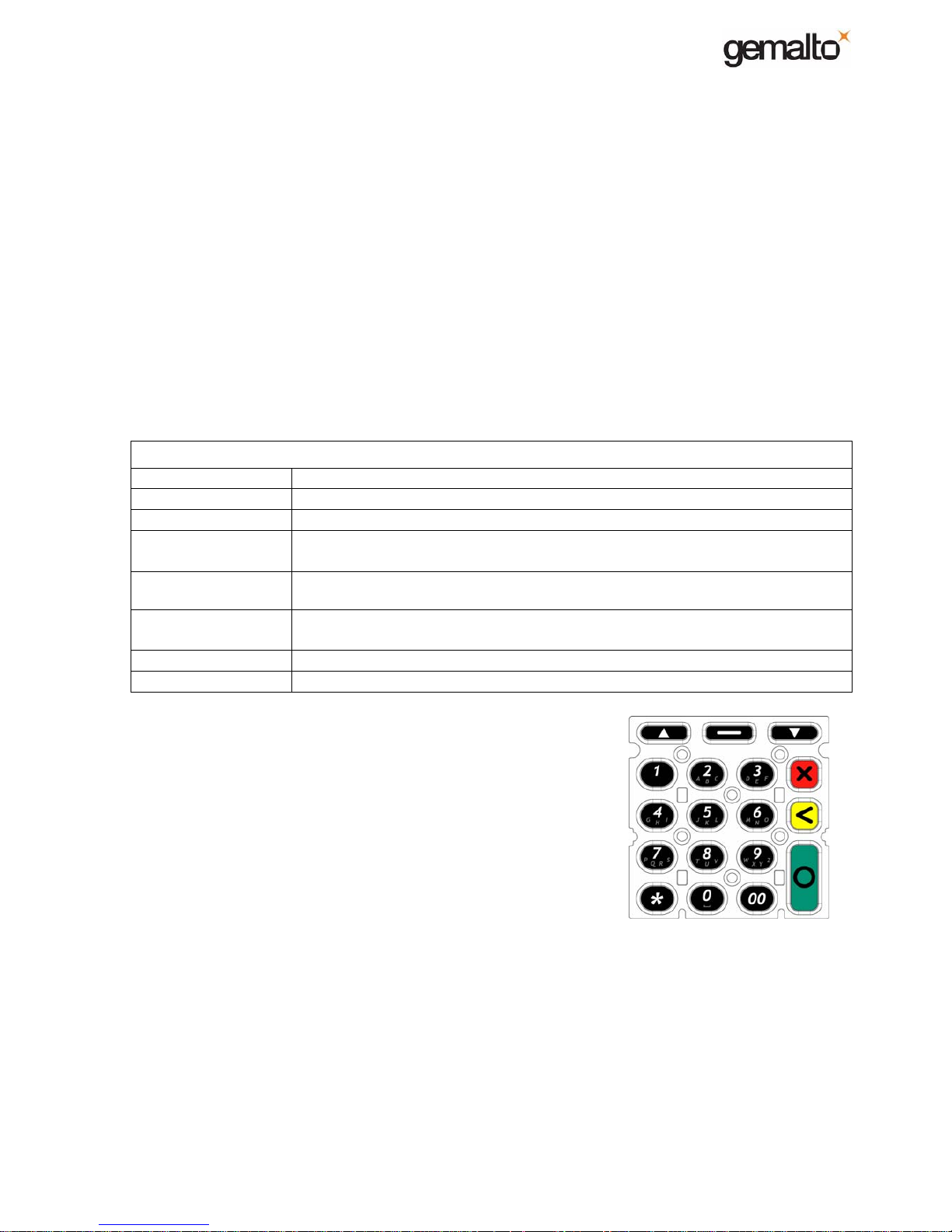
The keyboard consists of :
• A set of 3 cursor keys [U] [–] [V] without backlight
• A set of 15 keys with backlight, as follows:
• 11 numerical keypad: [0] – [9], [00]
• 4 function keys: [
*
] , [x]:cancel , [<]:clear , [O]:enter
• Keys [0] – [9] have alphabet marking
• Key [5] has the blind point
Mechanically it consists of a silicon rubber membrane where each key is covered by a
plastic cap (known as plastic caps technology). The plastic caps cannot be removed from
their casing.
The backlight is optional but equipped in standard configuration. It is obtained by 4 LEDs
implemented on the keyboard PCB.
2.2.9 Buzzer
The buzzer is used for sound generation according to the software needs (e.g. keystroke).
Frequencies are under software control.
Page 12

E-Payment MagIC
3
M-series Handset - MAINTENANCE MANUAL
Chapter 1 : DESCRIPTION
Ref: 22000-02-MAN-I-08010 August 2009 Ch.1 - 12/35
Copyright Gemalto – 2008 No disclosure to a third party without prior written consent of Gemalto
2.2.10 Printer
The printer is a Fujitsu FTP628-MCL101 or equivalent. The main characteristics are :
• 384 dots / line ;
• Dot size 0.125 mm x 0.12 mm ;
• Printing speed = 15 lines/s (15 lines of 24 characters "0121345678901234567890123", font
16x8) ;
• Life time (paper feed length) = 50 Km for printing rate 25% max.
Note:
2 printer covers exist, first one allows to use a paper roll of 32 mm in diameter at the most,
second one allows to use a paper roll of 40 mm at the most.
2.2.11 USB
1 x USB 2.0 master, full speed and low speed (1.5 and 12 Mbps), 500 mA max.
2.2.12 Reset button
A reset buttom is accessible via plastic well on the bottom part of the terminal. The
activation of this buttom will lead to an hardware reset of the M-series. To make a reset,
introduce a paper clip in the well until activation of the reset buttom.
Note:
We recommend you to prefer this mean to make a reset. Other way consist by removing the
battery pack, but it is not suitable since you run the risk of dammaging the battery pack
connector.
2.2.13 Battery backup for Secure Processor
A lithium button cell of 3V - 230mA/h is used for the backup of the Secure Processor. It is
located on the keyboard pcb, and is not accessible. Its replacement requires the opening of
the terminal, triggering the tampering mechanism, leading to the erasure of the banking
keys.
When the Terminal is power-off or in case of Vcc failure, the SP is backed up via the battery
lithium cell, and the following security items continu to be active: Supply monitor on Vbat,
Temperature monitor, Intrusion monitor (mesh and switches) and key integrity violation.
Note that the SP Real Time Clock is backed up too.
The battery is identical to the one used on C-series. It allows 3-year lifetime for a terminal
powered 10 hours a day after 6 months storage.
The battery lifetime given here concerns a terminal stayed on shelf in normal storage
condition as specified by § 2.2.21 Environment Use.
Note:
When tampering, the Terminal shall be put back into operation using the Unlocking tool.
Only the secure processor is backed up, the application contexts are not.
For repair & manufacturing operations, the current of the battery can be checked via some PCB
pads, accessibles by opening the SIM door.
2.2.14 Radio communication
M-series integrates hardware solution (radio module + internal antenna) to work on
frequencies GSM 900/1800, or GSM 850/1900. The frequencies depend of the couple
(module + antenna) equipped in the Terminal. Associated to the good antenna, it is indeed
Page 13

E-Payment MagIC
3
M-series Handset - MAINTENANCE MANUAL
Chapter 1 : DESCRIPTION
Ref: 22000-02-MAN-I-08010 August 2009 Ch.1 - 13/35
Copyright Gemalto – 2008 No disclosure to a third party without prior written consent of Gemalto
possible to integrate either the Siemens MC55 or MC56 module. MC55 & MC56 are pinto-pin and mechanically compatible, as well as antennas.
MC55/56 features GPRS multislot class 10 and supports the GPRS coding schemes CS1
to CS4.
Antenna is linked to the radio module via coaxial cable inside the Terminal.
o Couple MC55 + antenna C0120 is used to address GSM 900 / DCS 1800 markets
(European for instance).
o Couple MC56 + antenna C0132 is used to address GSM 850 / PCS 1900 markets
(USA for instance).
Note:
Future evolution : New Siemens Quad band module MC55i will be used to replace MC55 &
MC56 module. That means, whatever the frequency, you will always use the same module : the
MC55i. But you will always need 2 different antennas since each antenna has been designed to
support only 2 bandwidths.
2.2.15 Battery pack / Charge manager
2.2.15.1 Battery pack
A Li-ion battery pack of 7.4V - 1150mA/h is used to maintain the Handset functional when
not power-on (typically the case when it is not on its Base & when not directly power-on via
its jack plug).
The Li-ion battery set consist in fact on 2 prismatic elements of 3.7V each.
This pack integrates a fuel gauge used for charge management and a protection circuit to
detect over & under-voltage.
It is located on the bottom side of the Handset, accessible by opening the SIM door. It is
connected to the Handset Main board via a connector 4 pts (Molex type).
2.2.15.2 Charge manager
A Li-ion (Li-Polymer) charge-management circuit is integrated on M-series to manage the
battery charge.
2.2.16 Power supply
Power supply must be Vin = 12V +/- 5%, I = 1.8A (maximum current required).
On the Handset, power comes from 2 sources:
• From PSU connected to jack connector located on the back side of Handset ;
• From Base via 2 of the 4 connectors located on the bottom side of the Handset.
Note:
The Battery pack must be present and charge enough before applying the power supply source.
The Handset does not boot without Battery pack even if power supply is present
.
2.2.17 Shut down / Wake up Functions
2.2.17.1 Power OFF / Power ON
2.2.17.1.1 Power OFF
When does the Handset go in power off ?
• By using software function (via AM menu for instance) ;
Page 14

E-Payment MagIC
3
M-series Handset - MAINTENANCE MANUAL
Chapter 1 : DESCRIPTION
Ref: 22000-02-MAN-I-08010 August 2009 Ch.1 - 14/35
Copyright Gemalto – 2008 No disclosure to a third party without prior written consent of Gemalto
• By removing the battery pack ;
• Upon AM decision, when Battery pack voltage is lower than 7,2V (AM shut down
security) ;
• Upon OS decision, when Battery pack voltage is lower than 6,8V (OS shut down
security in case of AM shut down security by-passed for any reason) ;
• Upon Battery pack voltage internal trigger (Security is included in the pack to cut
power in case of over/under voltage detection).
2.2.17.1.2 Power ON
Battery pack must be present and charge enough, that are the initial conditions to leave
power off. From this state, power on can be done by :
• Connecting PSU on the Handset jack connector ;
• Laying down the Handset to the Base (assuming Base is powered on) ;
• By typing the key DOWN (key must be pushed during 1s at least to wake up.
2.2.17.2 Power Sleep / Wake up
2.2.17.2.1 Power Sleep
The Handset goes in power sleep upon software decision (when Handset is in AM idle
mode for 10s for instance (Application dependent).
2.2.17.2.2 Wake up
The handset can leave the power sleep upon any key pressed, upon hardware trigger like
from communication devices, …. (in any case it is software dependent).
2.2.18 Communication with the Base
It is done via an USBh, Base can be considered like a Hub on which peripherals are
connected to.
Physically, it consists of 4 electrical contacts located on the bottom side of the Handset
(D+,D-, Gnd, Vin). When Terminal put on its Base, communication is done via this way.
2.2.19 Tamper detection mechanisms
The Handset is equipped with many different means of detection:
• Security features integrated in the Secure Processor, such as active shield, intrusion
sensors, environmental protection systems (Voltage, Frequency, UV and
Temperature) ;
• 6 switches are part of the keypad membrane ;
• The secure box is made of a 2-layer grid mesh PCB surrounded with 4 sidewalls (3
soldered to the secure box, the front wall to the keyboard PCB). The secure box is
connected to the keyboard PCB via one elastomeric connector. It defines a secure
area that protects the smart card reader and sensitive components ;
• A I/O of the display device and of the board-to-board
1
connector conveys a security
signal.
As soon as one of the means of detection triggers (grid mesh cutted or short-circuited,
elastomeric connector or keyboard switch disconnection, abnormal environmental
detection, ….), the Secure Processor goes immediately in security alert, leading to the
1
The board-to-board connector conveys signals from the keyboard to the main PCB.
Page 15

E-Payment MagIC
3
M-series Handset - MAINTENANCE MANUAL
Chapter 1 : DESCRIPTION
Ref: 22000-02-MAN-I-08010 August 2009 Ch.1 - 15/35
Copyright Gemalto – 2008 No disclosure to a third party without prior written consent of Gemalto
erasure of its secret keys, by the way the lost of all sensitive data contained by the Secure
Processor.
Actuators are held in place through the mechanical structure, between the front and the
bottom covers, the whole is maintained in position by screws. Mechanical construction is
designed in order to prevent access to sensitive components.
Note:
When tampering, the Handset shall be put back into operation using the Unlocking tool.
2.2.20 Mechanical element characteristics
¾ Plastic is ABS, UL94 HB (2)
¾ Other pieces are UL94 HB minimum
Note:
Evolution on going to introduce Handset lid in ABS+PC material (H2 - 2009)
2.2.21 Environment Use
¾ Operating
0°C to 40°C (32°F to 104°F), < 90% RH
¾ Storage
-20°C to 55°C (-4°F to 131°F)
2
Introduction of the handset lid in ABS+PC V0 planned Q4/2009
Page 16
E-Payment MagIC
3
M-series Handset - MAINTENANCE MANUAL
Chapter 1 : DESCRIPTION
Ref: 22000-02-MAN-I-08010 August 2009 Ch.1 - 16/35
Copyright Gemalto – 2008 No disclosure to a third party without prior written consent of Gemalto
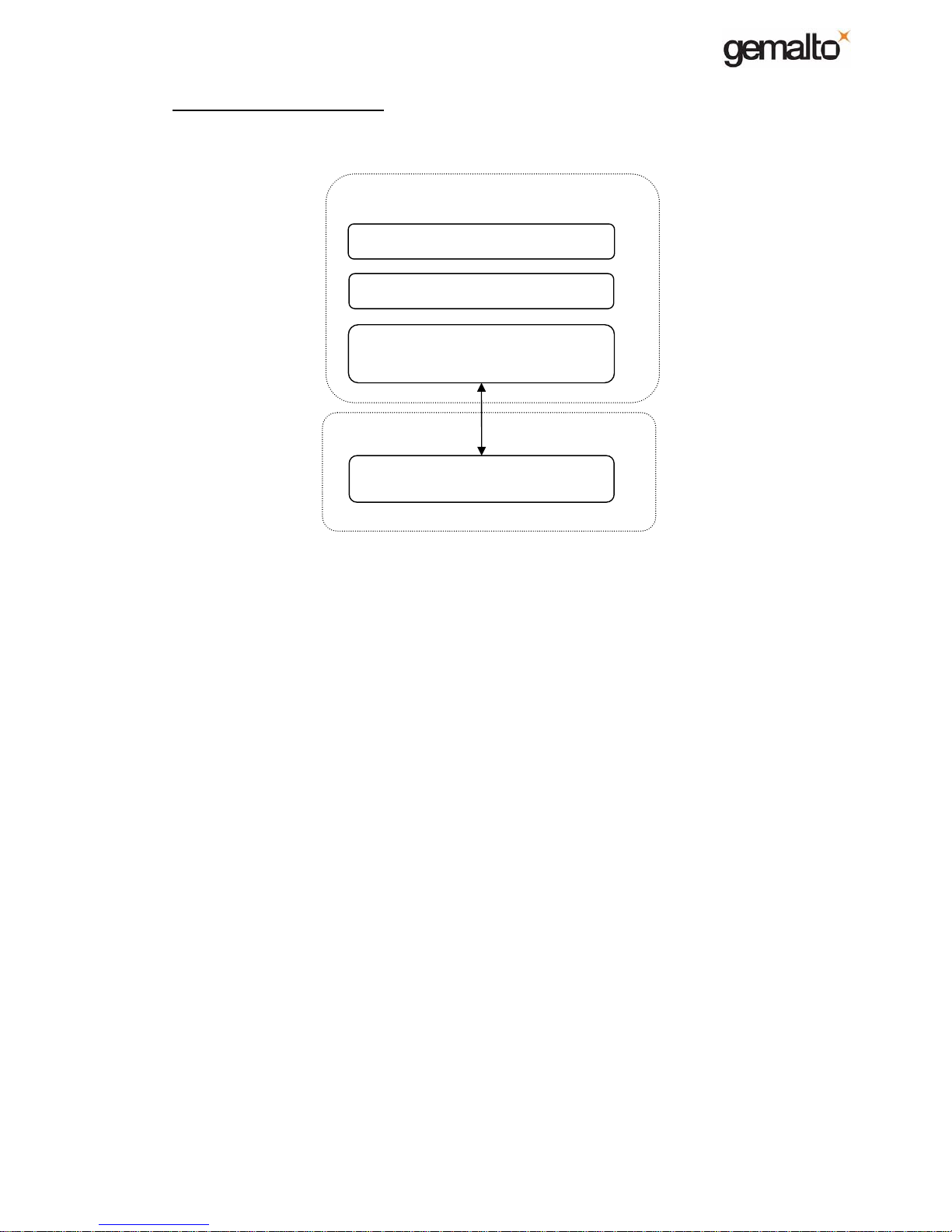
3. Software Architecture
Following diagram describes software architecture on MagIC3 terminal
The main processor runs applications and application manager over the operating system
based on an embedded version of Linux.
The operating system ensures a strong fire walling between applications and allows multitasking operations inside each application. It provides communication drivers for serial
ports, Ethernet, Modem and USB devices. The OS completely manages local software
downloading through USB keys, and on the Base through USB keys, USB cable and
remote TCP/IP downloading from the TMS through Ethernet or Modem.
The application manager is in charge of selecting the correct application for each
transaction. It also puts in common transactional services such as currencies, accounts,
total, merchants and messages management. It is up to the AM to handle idle screen and
all terminal management menus to setup terminal date, printer and display contrast, ticket
headers and footers, remote downloading parameters, etc.
The secure firmware is entirely contained in secure processor internal memory. It is in
charge of managing all sensitive devices related to the transaction process (display,
keyboard, smart cards and magnetic cards). The firmware also securely stores and
manages banking secret keys. Numeric and alphanumeric prompts are completely handled
by the secure processor to avoid fake PIN entries, and all messages used to prompt user
for data are authenticated by the secure firmware. This firmware will detect terminal
tampering and attacks and will block security features when such event occurred.
Main processor
Secure processor
Banking applications
Application Manager
Operating system
(based on Linux)
Secure firmware
Page 17

E-Payment MagIC
3
M-series Handset - MAINTENANCE MANUAL
Chapter 1 : DESCRIPTION
Ref: 22000-02-MAN-I-08010 August 2009 Ch.1 - 17/35
Copyright Gemalto – 2008 No disclosure to a third party without prior written consent of Gemalto
END OF CHAPTER 1
Page 18
E-Payment MagIC
3
M-series Handset - MAINTENANCE MANUAL
Chapter 2 : TROUBLESHOOTING
Ref: 22000-02-MAN-I-08010 August 2009 Ch.2 - 18/35
Copyright Gemalto – 2008 No disclosure to a third party without prior written consent of Gemalto
II) - TROUBLESHOOTING
1. Introduction
1.1 Methodology
The aim of this chapter is to provide assistance to operators in charge of corrective
maintenance, when the symptom of the failure is not obvious or corresponds to
different kinds of malfunction.
The instructions hereafter will inform on how to operate safely, locate the faulty unit
and identify the failure in a logical way.
1.1.1 Reference (MI)
The references (MI) linked to the troubleshooting procedures relate to procedures
listed in the MAINTENANCE part, chapter 3 of MAINTENANCE MANUAL.
1.1.2 Reference (T)
References (T) relate to the auto-test that can be run with Maintenance Software
MagIC
3
-Diag (refer to RI [02] for details).
1.2 Safety regulation
When the equipped boards are manipulated, these recommendations must be followed
to prevent electrostatic discharges:
• Use anti-static wrist and anti-static carpet
• Follow all the standard procedures for manipulation of SMD equipped PCBs.
1.3 Special tools and test equipment
• Tools
Cross shaped screwdriver Z (Pozidrive) :: PZ1 (diam. Max. 4.5mm).
Flat shaped screwdriver 3 x 75 mm.
Flat pliers.
• Test equipment Golden sample (reference Handset & reference Base).
Magnetic card ISO1/2/3.
SIM card (1 to 2 SIM).
Smart card.
• Diagnosis aid equipment Maintenance Software MagIC
3
-Diag (refer to RI [02])
Page 19

E-Payment MagIC
3
M-series Handset - MAINTENANCE MANUAL
Chapter 2 : TROUBLESHOOTING
Ref: 22000-02-MAN-I-08010 August 2009 Ch.2 - 19/35
Copyright Gemalto – 2008 No disclosure to a third party without prior written consent of Gemalto
1.4 Procedure
The troubleshooting operation must always follow the general
procedure below :
¾ Make sure the software configuration is coherent and
operational.
¾ You are aware of information related to
ELASTOMERIC by reading MI 16.
¾ Before opening the Handset, make sure that cables
(power supply and USB device) are disconnected.
The Handset must be put in power off before opening
it.
¾ If you open the Handset during repair operation, Get
into the habit of checking the LITHIUM_BAT voltage.
We recommend to change the LITHIUM_BAT if Vbat
< 2,9V (or if it is 3 years old).
¾ Always start analyse by checking the
BATTERY_PACK first (§ 2.1).
Page 20
E-Payment MagIC
3
M-series Handset - MAINTENANCE MANUAL
Chapter 2 : TROUBLESHOOTING
Ref: 22000-02-MAN-I-08010 August 2009 Ch.2 - 20/35
Copyright Gemalto – 2008 No disclosure to a third party without prior written consent of Gemalto
2. Troubleshooting Instructions
2.1 BATTERY-PACK failure
2.1.1 Symptoms
- The Handset does not boot (absence of any information on the display, no backlight
(display & keyboard) , no “beep” at boot time.
- The Handset boots but it shuts down very quickly.
- The BATTERY_PACK goes flat very quickly.
- The Handset boots but the BATTERY_PACK is not recognized, then the OS keeps
the control by displaying “Unknown Battery”.
When no boot or boot+shut down, the rootcause can be either BATTERY_PACK itself, or some
components of the Handset (charge manager circuit for instance).
2.1.2 Procedure
Battery pack failure Ref.
1. Make sure you reproduce the issue with a reference BATTERY_PACK. T
2. If the failure disappears, change the BATTERY_PACK. MI 17
3. If the failure is still present, change the PCB_MAINBOARD by a new one, MI 13
2.1.3 Battery pack control
Procedure Ref.
1. Check BATTERY_PACK cable and connector.
2. Check voltage Vbat
¾ 7,2V ≤ Vbat ≤ 8,4V : The Handset must be operational.
¾ 6,8V ≤ Vbat < 7,2V : Vbat is under the AM shut down trigger. The AM goes in
power-off when Vbat < 7,2V.
¾ Vbat < 6,8V : Vbat is under the OS shut down trigger. The OS goes in power-off
when Vbat < 6,8V (OS shut down security in case of AM shut down security bypassed for any reason).
¾ Vbat ~ 0V : The BATTERY_PACK is in security state. The handset does not boot
any more. The pack is protected in voltage and current, it goes in security state
upon over charge, or discharge, or current detection. To restore the pack, you just
need to charge it by powering the Handset via the Base or directly via the power
supply. Note that, as soon as charge starts, Vbat increases very quickly over 6,8V
and the Handset boots.
MI 18
3. Put the BATTERY_PACK in charge (even if Vbat ~ 0V) on a reference Handset.
Complete charge must be reached in less than 90 minutes.
4. From MagIC3-Diag main menu (assuming you do not activate any function), a full
charged BATTERY_PACK takes ~ 10 hours to reach the OS shut down trigger.
Page 21
E-Payment MagIC
3
M-series Handset - MAINTENANCE MANUAL
Chapter 2 : TROUBLESHOOTING
Ref: 22000-02-MAN-I-08010 August 2009 Ch.2 - 21/35
Copyright Gemalto – 2008 No disclosure to a third party without prior written consent of Gemalto
2.2 POWER SUPPLY failure
2.2.1 Symptoms
- The Handset does not see the power supply connected to its power jack.
2.2.2 Procedure
Power supply failure Ref.
4. Before opening the Handset, make sure you reproduce the issue with a reference
power supply.
5. If the failure disappears, change the power supply (even though the power supply
seems the root cause, check the power jack of the PCB_MAINBOARD, it might be
the problem)
6. If the failure is still present, change the PCB_MAINBOARD by a new one, MI 13
2.2.3 PSU control
1. Disconnect the power supply from the terminal.
2. Connect the power supply to the electrical wall plug.
3. Measure the DC output with a DC voltmeter, without charge and with a charge like a
reference terminal.
4. The voltage must be comprised between 11.65V and 12.35V.
Page 22
E-Payment MagIC
3
M-series Handset - MAINTENANCE MANUAL
Chapter 2 : TROUBLESHOOTING
Ref: 22000-02-MAN-I-08010 August 2009 Ch.2 - 22/35
Copyright Gemalto – 2008 No disclosure to a third party without prior written consent of Gemalto
2.3 DISPLAY failure
2.3.1 Symptoms
- The terminal boots, bip occurs, but you note following behaviour(s) :
- No message displayed.
- No backlight.
- Bad contrast.
- Bad display positioning.
2.3.2 Procedure
Display failure Ref.
1. Check :
- DISPLAY flex is not damaged.
- DISPLAY flex is well positionned to the PCB_KEYBOARD.
- DISPLAY is correctly positioned in the HANDSET_LID.
If need, reposition the piece and/or change the DISPLAY (if damaged).
MI 5
MI 7
2. If the failure is still present, change the DISPLAY by a new one (if DISPLAY
already changed in 1, goto 3 directly).
MI 7
3. If the failure is still present, change the PCB_KEYBOARD by a new one. MI 5
2.4 KEYBOARD failure
2.4.1 Symptoms
- No response of the terminal when a key is pressed.
2.4.2 Procedure
Keyboard failure Ref.
1. Before opening the Handset, verify that no key is blocked, release the root
cause of blocking if need. End of procedure.
2. Check the KEYPAD membrane (silicon keypad or/and carbon pills may be
damaged). Change it if damaged.
During this operation, check the pads of the PCB_KEYBOARD (dust, corrosion,
etc…), clean them if possible, or change the PCB_KEYBOARD if need.
MI 6
MI 5
3. If the failure is still present after having changed only the KEYPAD membrane,
then change the PCB_KEYBOARD too.
MI 5
Page 23

E-Payment MagIC
3
M-series Handset - MAINTENANCE MANUAL
Chapter 2 : TROUBLESHOOTING
Ref: 22000-02-MAN-I-08010 August 2009 Ch.2 - 23/35
Copyright Gemalto – 2008 No disclosure to a third party without prior written consent of Gemalto
2.5 PRINTER failure
2.5.1 Symptoms
- Printing operation interrupted.
- No ticket printed or driven out.
- Blank ticket or partly printed.
2.5.2 Procedure
Printer failure Ref.
1. Before opening the Handset, check if the PAPER_ROLL and PLATEN_ROLLER
are present and well positioned, verify that the PRINTER_LID is correctly
closed.
MI 2
2. Check :
- Printer flex is not damaged.
- Printer flex is well connected to the PCB_MAINBOARD.
- PRINTER is correctly positioned in the HANDSET_BOTTOM.
- PRINTER is correctly fixed to its support.
If need, reposition the piece and/or change the PRINTER (flex damaged).
MI 11
3. If the failure is still present, change the PRINTER by a new one (if PRINTER
already changed in 2, goto 4 directly).
MI 11
4. If the failure is still present, change the PCB_MAINBOARD by a new one. MI 13
Page 24
E-Payment MagIC
3
M-series Handset - MAINTENANCE MANUAL
Chapter 2 : TROUBLESHOOTING
Ref: 22000-02-MAN-I-08010 August 2009 Ch.2 - 24/35
Copyright Gemalto – 2008 No disclosure to a third party without prior written consent of Gemalto
2.6 MAGNETIC READER failure
2.6.1 Symptoms
- No reaction of the terminal after the card has been swiped in the reader.
- Occurrence of an error message on the display after card swiped.
2.6.2 Procedure
Magnetic reader failure Ref.
1. Check :
- Magnetic reader connector is in place.
- Cable is not damaged.
- MAG_HEAD support is correctly inserted in the HANDSET_BOTTOM.
- MAG_HEAD is correctly inserted in the MAG_HEAD support.
If need, reposition the piece and/or change the MAG_HEAD (if damaged)
MI 9
2. If the failure is still present, change the MAG_HEAD by a new one (if
MAG_HEAD already changed in 1, goto 3 directly).
MI 9
3. If the failure is still present, change the PCB_MAINBOARD by a new one. MI 13
Page 25

E-Payment MagIC
3
M-series Handset - MAINTENANCE MANUAL
Chapter 2 : TROUBLESHOOTING
Ref: 22000-02-MAN-I-08010 August 2009 Ch.2 - 25/35
Copyright Gemalto – 2008 No disclosure to a third party without prior written consent of Gemalto
2.7 CUSTOMER SMART CARD READER failure
2.7.1 Symptoms
- Absence of reaction of the terminal after the card has been introduced into the reader.
- Occurrence of an error message on the display after reading card.
2.7.2 Procedure
Customer smart card reader failure Ref.
1. Check the CARD_READER & CARD_READER_BOX (foreign body, fatty
substance, dust, etc …).
Clean the pieces if possible, change them if need.
MI 4
MI 5
2. If the failure is still present, change the PCB_KEYBOARD by a new one. MI 5
2.8 SAM READER (SIM-sized) failure
2.8.1 Symptoms
- SIM-sized cannot be detected.
2.8.2 Procedure
SAM reader (SIM-sized) failure Ref.
1. Verify that the 6 screws are correctly tighten.
Check SIM slot (foreign body, fatty substance).
Clean the piece if possible.
MI A
MI 13
2. If the failure is still present, change the PCB_MAINBOARD by a new one. MI 13
3. If the failure is still present, change the HANDSET_BOTTOM by a new one (steps
2 & 3 can be merged).
MI 13
4. If the failure is still present, change the PCB_KEYBOARD by a new one (since
these slots are interfaced to the secure processor located on keyboard pcb, this
might be the root cause of the issue, but stay the last point to check due to very low
probability).
MI 5
Page 26
E-Payment MagIC
3
M-series Handset - MAINTENANCE MANUAL
Chapter 2 : TROUBLESHOOTING
Ref: 22000-02-MAN-I-08010 August 2009 Ch.2 - 26/35
Copyright Gemalto – 2008 No disclosure to a third party without prior written consent of Gemalto
2.9 GSM INTERFACE failure
2.9.1 Symptoms
- PIN is not recognized (no access to the GSM SIM).
- GSM communication failed.
2.9.2 Procedure
GSM interface failure Ref.
1. Load and execute the maintenance software Magic3-Diag.
Launch the GPRS diagnostic function (Go to sub-menu “Select tests /
Communication / GPRS”). Keep in mind displayed message.
T
CASE : “GPRS MODULE NOK” Ref.
1. Check if the GSM_MODULE is well connected to the PCB_MAINBOARD. If well
connected, change the GSM_MODULE by a new one.
MI 12
2. If the failure is still present, change the PCB_MAINBOARD by a new one. MI 13
CASE : “GPRS SIM NOK” Ref.
1. Verify that the 6 srews are correctly tighten.
Check GSM SIM connector (foreign body, fatty substance, dust, etc …).
Clean the piece if possible.
MI 13
2. If the failure is still present, change the PCB_MAINBOARD by a new one. MI 13
3. If the failure is still present, change the HANDSET_BOTTOM by a new one (steps
2 & 3 can be merged).
MI 13
4. If the failure is still present, change the GSM_MODULE by a new one. MI 12
CASE : “GPRS ANTENNA NOK” Ref.
1. Check FLEX_ANTENNA (connector, cable, position).
If need, reposition the piece or change the FLEX_ANTENNA if damaged
MI 14
2. If the failure is still present, change the FLEX_ANTENNA by a new one (if already
changed in step 1, goto step 3 directly).
MI 14
3. If the failure is still present, change the GSM_MODULE by a new one. MI 12
4. If the failure is still present, change the PCB_MAINBOARD by a new one. MI 13
Page 27
E-Payment MagIC
3
M-series Handset - MAINTENANCE MANUAL
Chapter 2 : TROUBLESHOOTING
Ref: 22000-02-MAN-I-08010 August 2009 Ch.2 - 27/35
Copyright Gemalto – 2008 No disclosure to a third party without prior written consent of Gemalto
2.10 USB failure
2.10.1 Symptoms
- Impossibility to receive/transmit information from/to the USB link.
2.10.2 Procedure
USB failure Ref.
1. Verify that the USB cable is not damaged. Check the USB connector.
2. If Ok, change the PCB_MAINBOARD by a new one. MI 13
2.11 BASE CONTACT INTERFACE failure
2.11.1 Symptoms
- Base is not detected anymore.
- Communication failure between Handset and Base.
2.11.2 Procedure
Base contact interface failure Ref.
1. Before opening the Handset, make sure you reproduce the issue with a reference
Base & a reference power supply contected to this Base.
2. If the failure is still present, change the HANDSET_BOTTOM by a new one. MI 13
3. If the failure is still present, change the PCB_MAINBOARD by a new one. MI 13
Page 28

E-Payment MagIC
3
M-series Handset - MAINTENANCE MANUAL
Chapter 2 : TROUBLESHOOTING
Ref: 22000-02-MAN-I-08010 August 2009 Ch.2 - 28/35
Copyright Gemalto – 2008 No disclosure to a third party without prior written consent of Gemalto
2.12 SECURITY ALERT / LITHIUM BATTERY failure
2.12.1 Symptoms
- The message “security alert” appeared during the boot of the terminal.
- Although the terminal has been unlocked, after rebooting the terminal the
message “security alert” appeared again.
- The terminal constantly lost its system clock.
2.12.1.1 “SP Status” & Key List” Information
To investigate the causes of a tampered Terminal, you will have to print the “SP Status” & “Key List”
tickets.
To print these 2 tickets, go to OS MENU and select the sub-menus:
¾ “Security” & “SP Status” to obtain the status of the Security Processor
¾ “Security” & “Key List” to obtain the list of the keys present in the terminal.
2.12.2 Important information you have to know before starting
¾ Some switches and meshs are interlaced by design. It means that when the Secure
Processor records a mesh issue, the root cause can be also one of the switches!
¾ Besides, a switch is routed through the DISPLAY flex, it means that DISPLAY can
raise a switch issue too.
¾ Make sure that the root cause does not come from key issues, AUTH_SP &
AUTH_CUST keys must be present in the Terminal (refer to Software Customization
process Guide and Security training).
¾ Make sure that the Terminal is correctly screwed before continuing.
¾ Most of the case, when the system clock is lost, the Terminal is in security alert too,
and see by the Secure Processor as “Tampered”. After making sure the Terminal lost
well its system clock, you can go directly in the procedure to the case “System clock is
lost”.
All of that makes the procedure very tricky. Procedure has been written to focus to the most
usual root causes that lead to Security Alert (the probability that the DISPLAY is the root
cause is very low in comparison with KEYPAD and GRID_MESH_BOX).
Page 29
E-Payment MagIC
3
M-series Handset - MAINTENANCE MANUAL
Chapter 2 : TROUBLESHOOTING
Ref: 22000-02-MAN-I-08010 August 2009 Ch.2 - 29/35
Copyright Gemalto – 2008 No disclosure to a third party without prior written consent of Gemalto
2.12.3 Procedure
SECURITY ALERT / LITHIUM BATTERY failure Ref.
(I) Load and execute the maintenance software Magic3-Diag.
Go to sub-menu “Select tests / Security” , check displayed message and follow
procedure according to the message.
T
CASE : “Switch opened” Ref.
1. A switch running in the KEYPAD or/and in the DISPLAY is currently opened.
Change the KEYPAD.
KEYPAD is certainly the root cause, but since Terminal is open :
- Check the PCB_KEYBOARD on a reference Terminal (a golden sample), and
change it if failure occurs.
- Verify that the DISPLAY flex is correctly connected.
MI 6
MI 5
CASE : “Mesh opened” Ref.
1. Mesh or/and Switch is currently opened.
Check the GRID_MESH_BOX continuity. If the continuity fails, change
GRID_MESH_BOX & ELASTOMERIC connector (position A).
MI 3B
MI 3
2. If GRID_MESH_BOX was OK or if the failure is still present after having
changed it, then change the KEYPAD.
KEYPAD is certainly the root cause, but since Terminal is open :
- Check the PCB_KEYBOARD on a reference Terminal (a golden sample), and
change it if failure occurs.
MI 6
MI 5
Procedure continues next page ↓
Page 30
E-Payment MagIC
3
M-series Handset - MAINTENANCE MANUAL
Chapter 2 : TROUBLESHOOTING
Ref: 22000-02-MAN-I-08010 August 2009 Ch.2 - 30/35
Copyright Gemalto – 2008 No disclosure to a third party without prior written consent of Gemalto
CASE : “Tampered” Ref.
1. That means Meshs & Switches are currently OK, but an intrusion has occurred.
To know what was the security trigger that occurred, you can print the SP Status
ticket.
2. Through this ticket you have some information about current state, but above all,
about last event occurred in the past too
.
3. Read UKSR (Curr) line.
If = 0xX1XXXXXX, it means transient Mesh issue occurred on field (
3
)
If = 0xX2XXXXXX, it means transient Switch issue occurred on field
If = 0xX3XXXXXX, it means transient Mesh & Switch issue occurred on field
If = 0xX0XXXXXX, print the “Key List” ticket and verify that AUTH_SP &
AUTH_CUST keys are well present in the Terminal.
Such information can help you to manage a Terminal that come back in repair
many times
with as indication “Tampered”. Although Meshs & Switches are
currently OK, you face to a transient phenomenon that occurs on field. In this
case, manage this problem as if the Mesh or/and Switch was currently opened.
Note: UKSR (Curr) information are reset when you Unlock the Terminal. It
means, above analyse must be done before Unlocking the Terminal.
CASE : System clock is lost Ref.
1. Check LITHIUM_BAT voltage. If Vbat < 2,9V , then change the LITHIUM_BAT.
Note that (independently of result) we recommend to change the
LITHIUM_BAT if it is 3 years old.
Note that, before opening the Terminal to check the LITHIUM_BAT, you can
check information returned by SP Status ticket.
If UKSR (Curr) = 0xXXX8XXXX, it means that LITHIUM_BAT voltage is too
low. LITHIUM_BAT must be changed.
MI 15B
MI 15
2. If Vbat was OK or if the failure is still present after having changed the
LITHIUM_BAT, then change the PCB_MAINBOARD.
MI 13
3. At the end, If the failure is still present then change the PCB_KEYBOARD. MI 5
3
Remember, on this Terminal, some switches and meshs are interlaced by design. It means that when the
Secure Processor records a mesh issue, the root cause can be also one of the switches.
Page 31
E-Payment MagIC
3
M-series Handset - MAINTENANCE MANUAL
Chapter 2 : TROUBLESHOOTING
Ref: 22000-02-MAN-I-08010 August 2009 Ch.2 - 31/35
Copyright Gemalto – 2008 No disclosure to a third party without prior written consent of Gemalto
3. SECURITY ALERT – How to interprete SP Status information
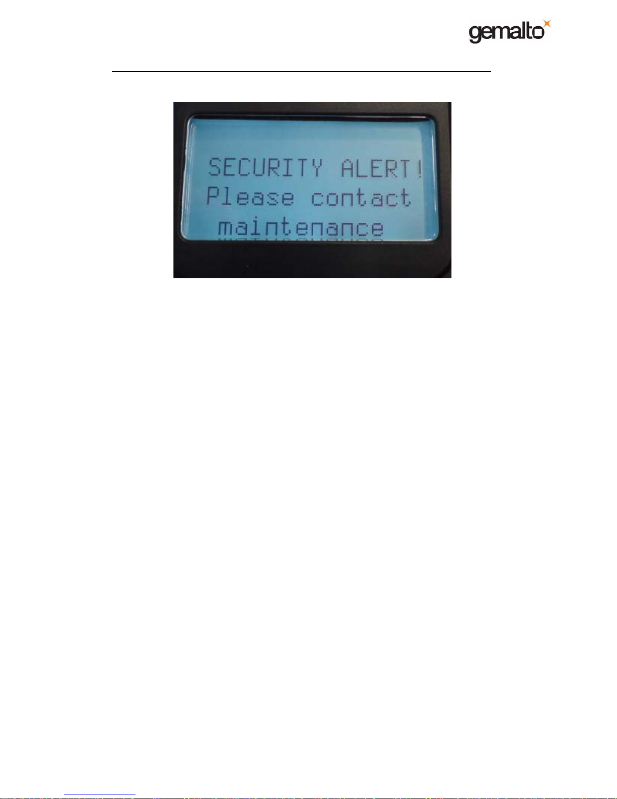
If the security has been tampered, a “SECURITY ALERT” message
will be displayed for few seconds at boot time.
Unlike X-series, there is no more “Key Icon” on the Display to indicate
when the security has been triggered.
!! Below content gives you some detailed information about Security Alert.
This can be usefull when you did not success by following procedure
described in §2.12. Remember, always starting by procedure §2.12 to
analyse Security Alert before going in the below information.
Page 32

E-Payment MagIC
3
M-series Handset - MAINTENANCE MANUAL
Chapter 2 : TROUBLESHOOTING
Ref: 22000-02-MAN-I-08010 August 2009 Ch.2 - 32/35
Copyright Gemalto – 2008 No disclosure to a third party without prior written consent of Gemalto
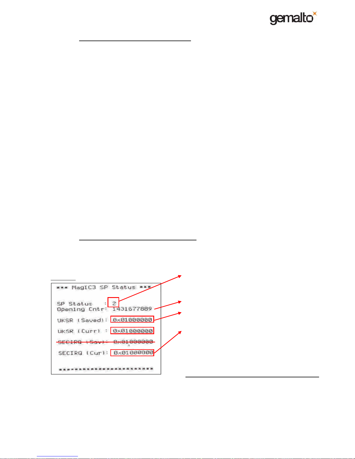
3.1 SP STATUS ticket information
Look at the ticket that is printed: *** MagIC3 SP Status ***
SP Status : 0
¾ 0 : OK. At least AUTH_SP and AUTH_CUST keys have been loaded and no attack has been
detected. The Terminal is not tampered.
¾ 1 : Reserved for Manufacturing.
¾ 2 : NOK. Multiple causes (Physical and/or Keys issue):
¾ AUTH_SP = 0x1 (default key) :: you must load an AUTH_SP + AUTH_CUST (
4
).
¾ AUTH_SP loaded but not AUTH_CUST :: you must load AUTH_CUST.
¾ Security keys are present but an attack has been detected by the Security Processor :: you
must investigate security registers to identify the root cause (Mesh opened, switch opened,
low voltage on the lithium buttom cell, …).
Opening Cntr : 0
Number of times the Terminal was opened from the last load of AUTH_SP key. Feature supported
from FWSP 1.10.00. Besides, if the firmware is upgraded from versions below 1.10.00, this value is
meaningless.
UKSR (Sav) : 0x00000000
Value of the UKSR (Curr) before the last Unlock operation. Please, read UKSR (Curr) to understand
usefulness of UKSR (Sav). Note that b0 of UKSR (Sav) is always 0.
UKSR (Curr) : 0x00000001
This register gives some information about the last event impacting the security state. When (at
least) AUTH_SP and AUTH_CUST have been loaded and no attack has been detected, the UKSR
(Curr) must be equal to 0x00000001.
As soon as an attack is detected, this register changes and indicates the origin of the SECURITY
ALERT (mesh or switch for instance). Then, an image of UKSR (Curr) is copied in UKSR (Sav).
UKSR (Curr) keeps the information while it has not been reset by unlocking operation. Unlocking
operation reset the UKSR (Curr) to 0x00000001.
When a terminal has been unlock, if you want to know what was the last event that impacted the
security state, you just need to read UKSR (Sav).
SECIRQ (Sav) : 0x00000000
R&D relevant only.
SECIRQ (Cur) : 0x00000000
Consider that this register works like UKSR (Curr), with one important exception. Unlike UKSR
(Curr), SECIRQ (Cur) does not keep the information. Its state is refreshed in real time. It is usefull to
know the current
state of the security triggers.
4
Terminal is in this state when it has not been personalized, or perzonalized failed
Page 33
E-Payment MagIC
3
M-series Handset - MAINTENANCE MANUAL
Chapter 2 : TROUBLESHOOTING
Ref: 22000-02-MAN-I-08010 August 2009 Ch.2 - 33/35
Copyright Gemalto – 2008 No disclosure to a third party without prior written consent of Gemalto
3.2 UKSR/SECIRQ values meanings
Let's 0xAABBCCDD
AA ORred values:
0x01 : [MESH] : This bit is set when upon gridmesh attack.
0x02 : [SWITCH] : This bit is set upon switch attack.
0x04 : [TAMPER] : Tamper attack on the chip. (i.e. shield attack on the Secure Processor).
BB ORred values:
0x08 : [VBACKUPSML] : This bit is set due to a low voltage on the lithium buttom cell.
CC ORred values:
Not relevant
DD ORred values:
0x02 : [SOFT] : This bit is set when AUTH_SP & AUTH_CUST keys have been erased
by a RESET process. Reload the 2 keys to enable the security
protection of the Terminal. Note that if you load only AUTH_SP (without
AUTH_CUST), this bit will not be reset.
0x08 : [VBACKUPRST] : Lithium cell power has been cut for few seconds (or more). Note, on C-
series, as soon as you open the terminal, this bit is set to 1 (due to the
lithium cell power that is cut when the board-to-board connector is
opened).
3.3 Interpreting UKSR/SECIRQ values
All those values can be added to another one of the same category. Ex: SECIRQ (Cur) =
0x03000001 indicates that the terminal has currently an issue on the mesh (0x01xxxxxx) and switch
(0x02xxxxxx).
Don’t pay attention to the non relevant values.
Example:
¾ A status 2 means two things:
- Either AUTH_CUST key is not loaded
- Or attack has been detected
¾ On this case, this value is meaningless (see above)
¾ The last time security triggered, it was due to a
MESH issue (see below)
¾ The security state is still TAMPERED because of a
MESH issue is still present (see below)
0x AA BB CC DD
0x 01 00 00 00
Let’s decode this value:
AA value = 0x01:
It’s a mesh issue, and the issue is still present!
Page 34
E-Payment MagIC
3
M-series Handset - MAINTENANCE MANUAL
Chapter 2 : TROUBLESHOOTING
Ref: 22000-02-MAN-I-08010 August 2009 Ch.2 - 34/35
Copyright Gemalto – 2008 No disclosure to a third party without prior written consent of Gemalto
Some other examples :
SP Status
2
SECURITY ALERT
UKSR (Sav) 01 00 00 00 = UKSR (Curr)
UKSR (Curr) 01 00 00 01 The root cause is the mesh (5)
SECIRQ (Sav xx xx xx xx NOT RELEVANT
SECIRQ (Cur) 00 00 00 00 The issue on the mesh has disappeared
SP Status
2
SECURITY ALERT
UKSR (Sav) 03 00 00 00 = UKSR (Curr)
UKSR (Curr) 03 00 00 01 The root cause is a mesh + switch(es)
SECIRQ (Sav xx xx xx xx NOT RELEVANT
SECIRQ (Cur) 02 00 00 00 The issue on the switch is still present, but not on the mesh
SP Status
0
SECURITY is Ok (AUTH_SP & AUTH_CUST have been loaded and terminal
is not tampered)
UKSR (Sav) 02 00 00 00 We can see that the last SECURITY ALERT was due to a switch
UKSR (Curr) 00 00 00 01 No attack since last unlock
SECIRQ (Sav xx xx xx xx NOT RELEVANT
SECIRQ (Cur) 00 00 00 00 All security triggers are currently Ok
SP Status
2
SECURITY ALERT
UKSR (Sav) 01 00 00 00 Not relevant in this example
UKSR (Curr) 00 00 00 03 Here we can see that SOFT is set, it means that the terminal underwent a
RESET process, and that since this operation, AUTH_SP & AUTH_CUST
keys have not been reloaded.
SECIRQ (Sav xx xx xx xx NOT RELEVANT
SECIRQ (Cur) xx xx xx xx Not relevant in this example
SP Status 2 SECURITY ALERT
UKSR (Sav) 00 08 00 00 = UKSR (Curr)
UKSR (Curr) 00 08 00 01 The root cause is the lithium cell voltage.
SECIRQ (Sav xx xx xx xx NOT RELEVANT
SECIRQ (Cur) 00 08 00 00 The issue is still present
SP Status 2 SECURITY ALERT
UKSR (Sav) 00 00 00 08 = UKSR (Curr)
UKSR (Curr) 00 00 00 09 The terminal has been open
SECIRQ (Sav xx xx xx xx NOT RELEVANT
SECIRQ (Cur) xx xx xx xx Not relevant in this example
bit0 of UKSR (Saved) is always 0
5
Remember, on this Terminal, some switches and meshs are interlaced by design. It means that when the
Secure Processor records a mesh issue, the root cause can be also one of the switches.
Page 35

E-Payment MagIC
3
M-series Handset - MAINTENANCE MANUAL
Chapter 2 : TROUBLESHOOTING
Ref: 22000-02-MAN-I-08010 August 2009 Ch.2 - 35/35
Copyright Gemalto – 2008 No disclosure to a third party without prior written consent of Gemalto
END OF CHAPTER 2
4 3
 Loading...