

Page 1
Index
Opening & Keyboard Disassembling Instructions
3
4
Autotest Procedure
Block Diagrams5
6
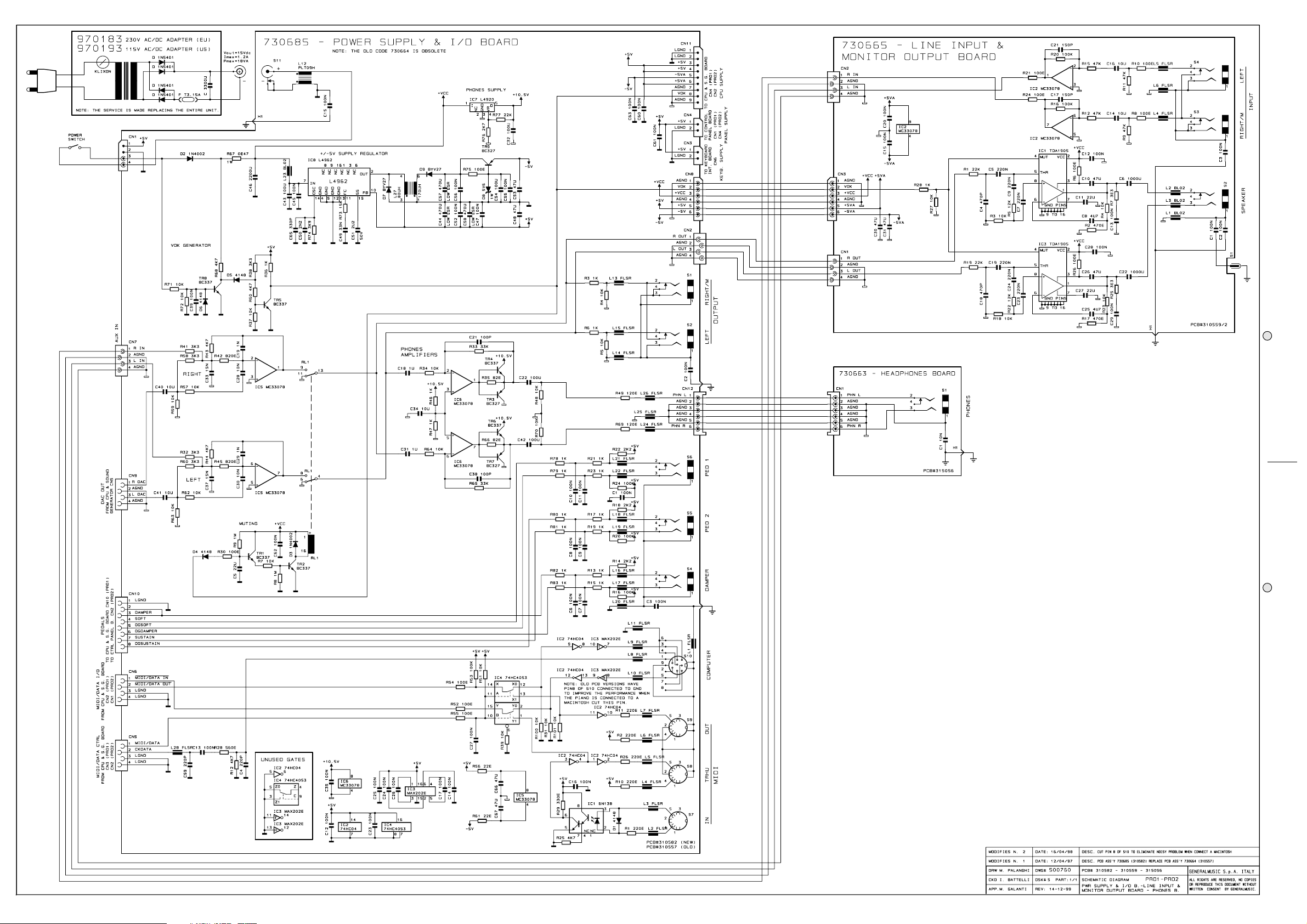
Power Supply & I/O, Line Input & Monitor Output Contact Schematics
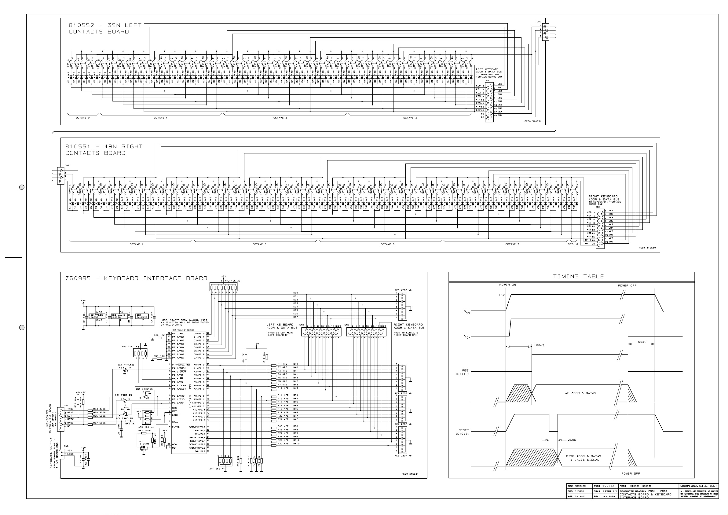
Contacts & Keyboard Interface Schematics, Timing Table7
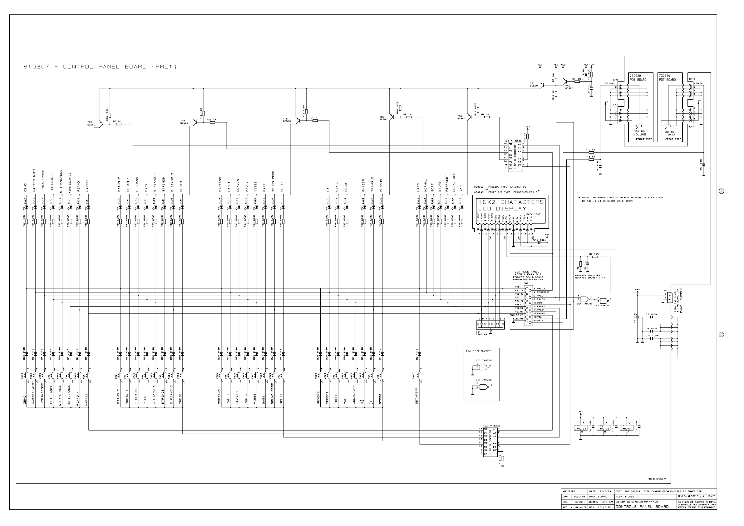
8 PRO1 Controls Panel Schematic
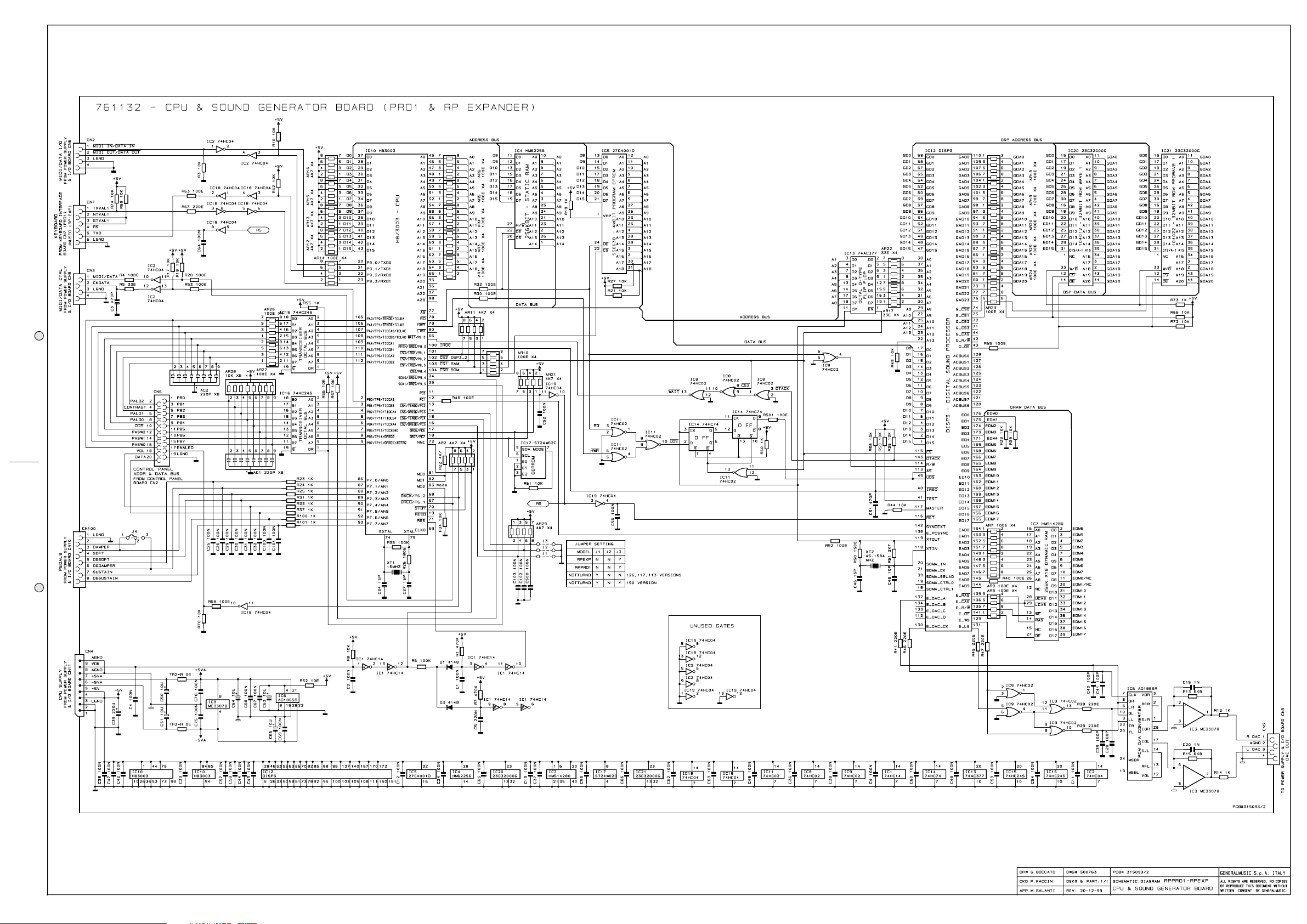
PRO1 Cpu & Sound Generator Schematic
9
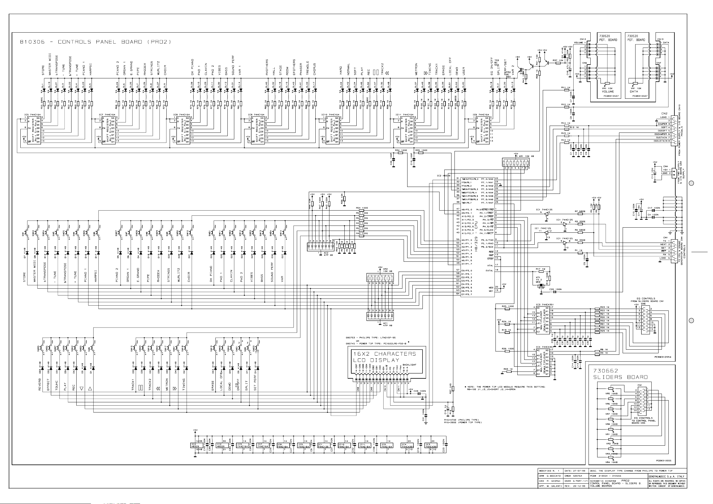
PRO2 Controls Panel Schematic10
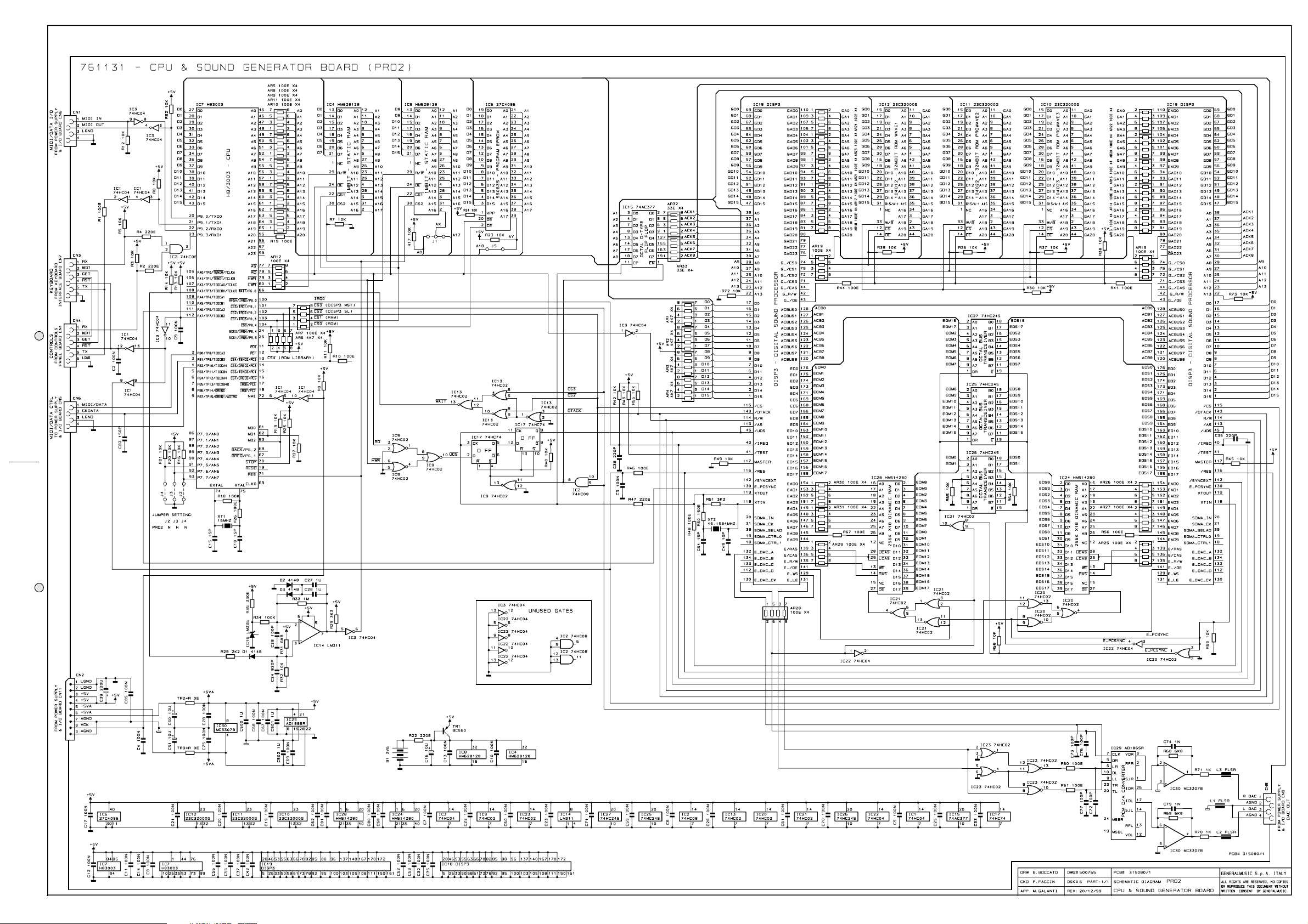
PRO2 Cpu & Sound Generator Schematic11
Spare Part List
12
SERVICE MANUAL
Warnings
Notice
Service must be carried out by qualified personnel only. Any tampering carried out by unqualified personnel during the guarantee period
✔
will forfeit the right to guarantee.
For a correct operation of the instrument, after having switched off, be careful to wait at least 3 seconds before switching on again.
✔
To improve the device's specifications, the schematic diagrams may be subject to change without prior notice.
✔
All components marked by this symbol have special safety characteristics, when replacing any of these components use only
manufacturer's specified parts.
The (µ) micro symbol of capacitance value is substituted by U.
✔
The (
✔
✔
✔
✔
✔
✔
✔
✔
Ω) omega symbol of resistance value is substituted by E.
The electrolytic capacitors are 25Vdc rated voltage unless otherwise specified.
All resistors are 1/8W unless otherwise specified.
All switches shown in the "OFF" position. All DC voltages measured to ground with a voltmeter 20KOhm/V.
Soldering point.
Male connector.
Female connector.
M/F faston connector.
ATTENTION
Address
Supply voltage. Logic supply ground.
Test point.
Flag joined with one or more flags
with the same signal name inscribed.
Observe precautions when handling electrostatic sensitive devices.
Analog supply ground.
Chassis ground.
Earth ground.
CODE: 270146
GENERALMUSIC S.p.A. Sales Division: 47842 S.Giovanni in Marignano (RN) ITALY - Via delle Rose, 12
✒
Phone 0541/959511 - Fax 0541/957404 - GENERALMUSIC on the NET: http://www.generalmusic.com
☎
JJ
1
J
JJ
Page 2

J J
J 2
J J
Page 3
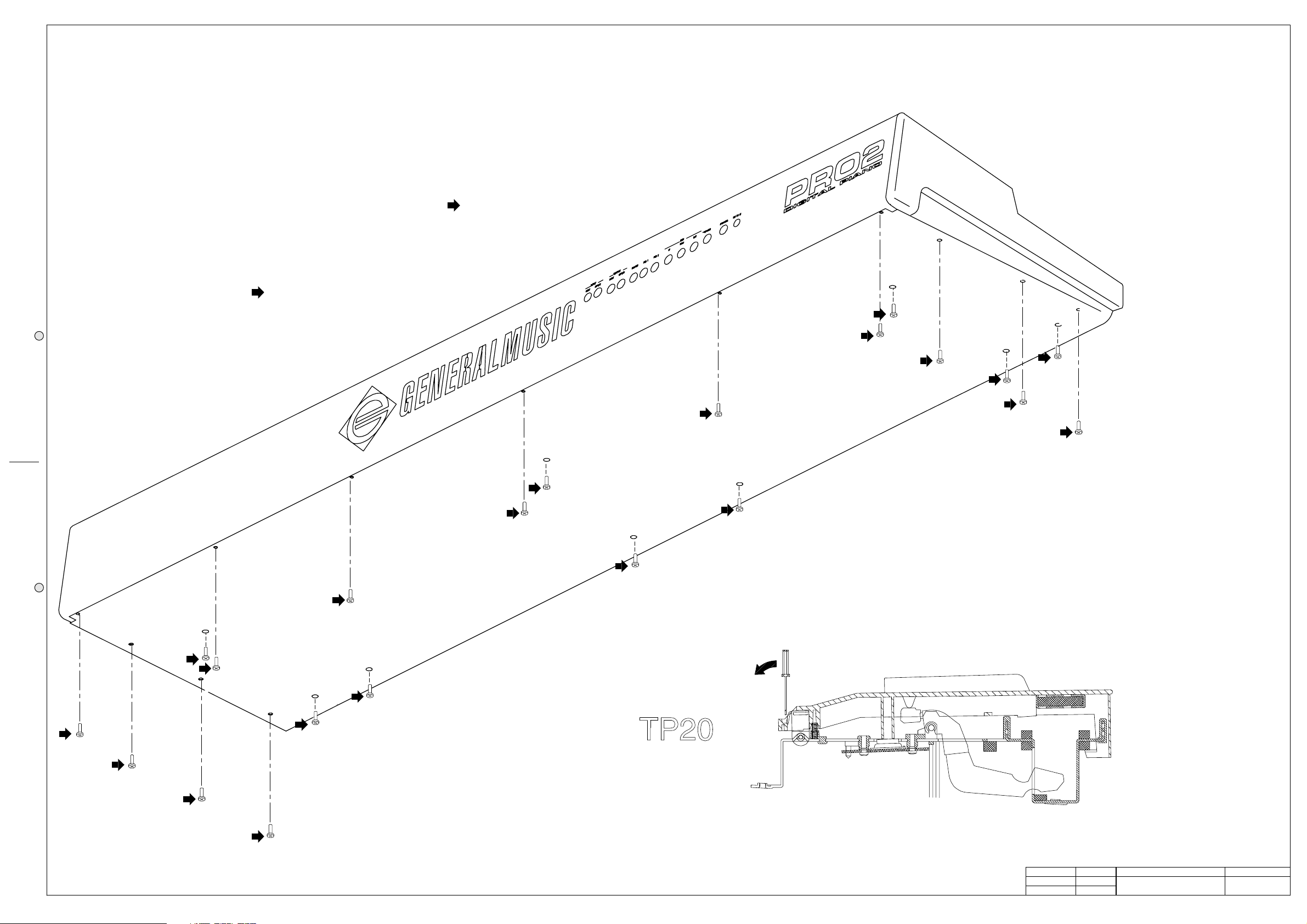
OPENING INSTRUCTIONS
To open the instrument remove the screws marked by an arrow
and lift up the top chassis.
KEYBOARD DISASSEMBLING INSTRUCTIONS
To separate the keyboard from the bottom chassis remove the
screws marked by the arrow
K
K
K
K
K
K
K
NOTE KEY DISASSEMBLING INSTRUCTIONS
To remove a key, insert a screwdriver or other similar object in the split
at the key back, apply a light pressure and push in the direction shown.
Note: Before you remove a natural key you must remove the
keyboard from the chassis (as shown above), if you remove a sharp key
K
K
K
this operation is not necessary.
DRW
CKD
APP.
G. BOCCATO
M. GALANTI
M. GALANTI
DWG#
500758
DISK:
61/1
REV:
23/12/99
PCB#
Opening & Disassembling Instructions
PRT:
GENERALMUSIC S.p.A. ITALY
ALL RIGHTS ARE RESERVED, NO COPIES
OR REPRODUCE THIS DOCUMENT WITHOUT
WRITTEN CONSENT BY GENERALMUSIC.
JJ
3
J
JJ
Page 4
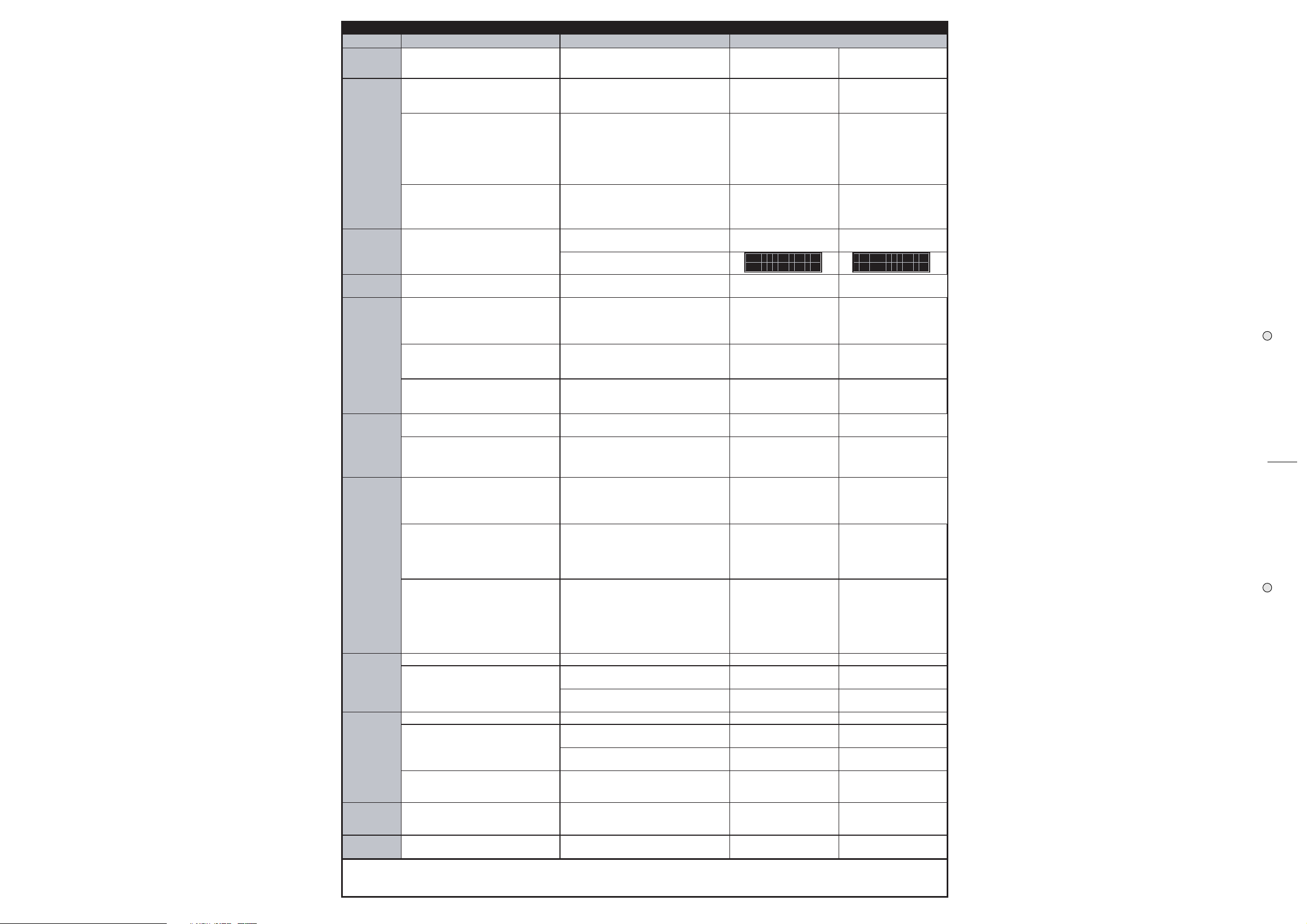
AUTOTEST CHART
RP 1 PRO RP 2 PRO
Test Operation Description Event Description Display
Start
Turn on the instrument while
holding pressed "SOUNDS" button.
A display message appears:
PRO1 AUTOTEST
-------------
PRO2 AUTOTEST
-------------
Memory
Display
LED
Buttons
Equalizer
(Pro2 only)
Press "SOUNDS" button.
Press "SOUNDS" button.
Press "SOUNDS" button.
Press "SOUNDS" button.
Press "SOUNDS" button. Check that all leds light on.
Press "SOUNDS" button.
Press the UP and DOWN arrow
buttons.
Press all panel buttons one by
one except "SOUNDS" button.
Press "SOUNDS" button. The display shows temporarely:
Display shows current software
version in EPROM:
The display shows a running dot
while the Piano calculates the eprom
checksum, after a few seconds the
checksum value is displayed, check it
with the hexadecimal code printed on
the eprom label.
The display shows the memory
address while the Piano checks the
SRAM, after a few seconds the final
address is displayed.
The display shows:
After a few seconds check that all
the display segments turn black.
Moving the VOLUME and DATA
potentiometers the display shows the
corresponding position number from 0
to 127.
Display shows U (up) or D (down)
letters on the left side.
Every button pressed must light
corresponding led.
Moving the Equalizer potentiometers
the display shows the corresponding
position number from 0 to 127.
month day year
hour:min:sec v#.##
Please wait OK
Checksum hhhh
RAM MEMORY CHECK
addr 2055BF OK
LCD DISPLAY TEST
----------------
--- LED Test --Are all leds on?
|Button Test
|Vol:vvv Pot:ppp
U|Button Test
D|Vol:127 Pot:127
U|Button Test
D|Vol:127 Pot:127
month day year
hour:min:sec v#.##
Please wait OK
Checksum hhhh
RAM MEMORY CHECK
addr 23FFFF OK
LCD DISPLAY TEST
----------------
--- LED Test --Are all leds on?
|Button Test
|Vol:vvv Pot:ppp
U|Button Test
D|Vol:127 Pot:127
U|Button Test
D|Vol:127 Pot:127
EQ POT TEST ...
----------------
111 222 333 444
555 666 777 888
J J
J 4
J J
Pedals
MIDI
Computer
Interface
Sinus Test
Exit
Note:
The display is shared in three
Press "SOUNDS" button.
Press "SOUNDS" button.
Loop the MIDI IN and OUT
connectors with a single MIDI
cable.
Press "SOUNDS" button.
Loop the pin 3 and 5 of the
COMPUTER socket.
Press "SOUNDS" button.
Press "SOUNDS" button. An end test message appears:
The autotest operations can be performed only in the sequence specified above.
During test all normal keyboard functions are disabled.
At the end of autotest a memory reset take place.
columns, one for each pedal damper
(Da), Pedal1 (Pe) and Pedal2 (Pe).
Inserting a footswitch pedal in each
socket the upper value must change
from 0 to 127 accordly to the pedal
position, the lower value must be
always 0.
Inserting a variable analogic pedal in
each socket the upper value changes
to its maximum value (usually
ranges from 110 to 120), the lower
value vary from 0 to the maximum
value accordly to the pedal position.
The display shows:
If loop is interrupted, display shows:
A display message appears:
If loop is interrupted, display shows:
Check with the oscilloscope a 1MHz
clock signal on pin 1 of the
COMPUTER socket.
The instrument plays a 1KHz
sinusoidal tone. TRANSPOSE buttons
should slightly modify frequency.
:Da###|Pe###|Pe###
:mp###|d1###|d2###
TEST MIDI IN/OUT
LOOP DETECTED OK
TEST MIDI IN/OUT
--- NO LOOP! ---
TST COMPUTER I/O
LOOP DETECTED OK
TST COMPUTER I/O
--- NO LOOP! ---
TEST TERMINATED!
SOUNDS to quit
SINUS SWEEP
Freq. 1000 Hz
:Da###|Pe###|Pe###
:mp###|d1###|d2###
TEST MIDI IN/OUT
LOOP DETECTED OK
TEST MIDI IN/OUT
--- NO LOOP! ---
TST COMPUTER I/O
LOOP DETECTED OK
TST COMPUTER I/O
--- NO LOOP! ---
SINUS SWEEP
Freq. 1000 Hz
TEST TERMINATED!
SOUNDS to quit
Page 5
JJ
5
J
JJ
Page 6
J J
J 6
J J
Page 7
JJ
7
J
JJ
Page 8
J J
J 8
J J
Page 9
JJ
9
J
JJ
Page 10
J J
J 10
J J
Page 11
11
JJ
J
JJ
Page 12
Spare Part List
Legend
EU = specify European Version (230Vac)
US = specify United States Version (115Vac)
PRO1 = for PRO1 version only
PRO2 = for PRO2 version only
GEM = Gem Brand Version
GM = Generalmusic Brand Version
Code Description
Accessories
970183 230V AC/DC Adapter (EU)
970193 115V AC/DC Adapter (US)
271099 Owner's Manual (All Languages)
970134 Piano Single Foot Switch
Optional Accessories
130301 2mt Midi Cable
970013 Volume Pedal
970107 Professional Volume Pedal
970116 Single Pedal Switch
970080 Triple Pedal Switch
970134 Piano Single Foot Switch
970266 Piano Triple Pedal (Soft, Sustain with Switches Damper with Pot.)
970310 Multimedia Kit
130429 * 3mt RS232 Cable (Mini-Din 8 to D-Sub9)
970110 X-Metal Stand
970300 50+50W Amplified Stand (EU)
970311 50+50W Amplified Stand (US)
Cabinet Assembly
Bottom Chassis
660524 Bottom Chassis
651583 Left Side
651582 Right Side
Top Chassis
660523 Top Chassis (PRO1) (GEM)
660522 Top Chassis (PRO2) (GEM)
660538 Top Chassis (PRO1) (GM)
660537 Top Chassis (PRO2) (GM)
653122 Keyboard Left Side
651585 Keyboard Right Side
653326 “<>” Pad
653121 "Store"..."Sounds” Pad
653120 “Sequencer” and "Eq On/Off" Pad
653119 "Var","Sounds","Reverb","Effect","Touch" Pad
653117 "Local/Off" and "Demo" Pad
653116 "Master/Midi" and "Perf/Edit” Pad
651648 Plexiglass Display Screen
347255 Equalizer Slider Knob
340820 Slider Knob
340523 6,5mm Spacer
340512 Slider Potentiometer Guide
340435 Adhesive Foot
340357 Spacer For Left & Right Side
340092 5mm Board Spacer
210258 Slider Potentiometer Felt
171544 CPU Board Support
171543 Printed Circuit Panel Support
171542 Holder Square
171397 Right Side Spacer
110285 Power Switch
Keyboard & Interface Assembly
720489 Keyboard Assembly with Interface
840762 * 20 Wires 25cm Length Flat Cable
840761 * 20 Wires 12.5cm Length Flat Cable
760995 * Keyboard Interface Board (PCB#315024)
141018 ** 20 Contacts Vert Female Connector
141011 ** 6 Contacts Vert Female Connector
140918 ** 2 Contacts Hor Male Connector
100740 ** HD6433278 Cpu F=20MHz
100605 ** 74HC125 Quad 3-State Buffer
050493 ** Resistor Array 10K X4 1/8w 5%
050492 ** 10Kx8 1/8w 5% Resistor Array
050414 ** 2K2 X4 1/8w 5% Resistor Array
010726 ** 19.2MHz Ceramic Resonator With Capacitors
010662 ** 220p 10% 50V X8 Cap Array
010661 ** 47p 10% 50V X8 Cap Array
720490 * 88N Keyboard Assembly (TP20)
810552 ** 39N Left Contacts Board (PCB#310531)
340764 *** 3 Dual Contacts Rubber Strip
340211 *** 12 Dual Contact Rubber Strip
141018 *** 20 Contacts Vert Female Connector
141010 *** 4 Contacts Vert Female Connector
080103 *** 1N4148 100mA 75V Signal Diode
810551 ** 49N Right Contacts Board (PCB#310530)
340212 *** 13 Dual Contact Rubber Strip
340211 *** 12 Dual Contact Rubber Strip
141018 *** 20 Contacts Vert Female Connector
141010 *** 4 Contacts Vert Female Connector
080103 *** 1N4148 100mA 75V Signal Diode
160211 ** Key Return Spring (TP20)
151172 ** Last C Key (TP20)
151171 ** First A Key (TP20)
151170 ** Sharp Key (TP20)
151169 ** B Key (TP20)
151168 ** A Key (TP20)
151167 ** G Key (TP20)
151166 ** F Key (TP20)
151165 ** E Key (TP20)
151164 ** D Key (TP20)
151163 ** C Key (TP20)
Power Supply & I/O Board
730685 Power Supply & I/O Board (PCB#310582)
340138 * Dc-Socket Reinforcement
230569 * FL5R200PNT EMI Coil For Signal
230566 * 80/170uh 1,5a Switching Double Coil
230559 * 20uH 50V 3A Dc Line Filter
230527 * BL02RN2-R62 EMI Coil For Signal
141012 * 8 Contacts Vert Female Connector
141010 * 4 Contacts Vert Female Connector
140929 * 9 Contacts Vert Male Connector
140917 * 2 Contacts Vert Male Connector
140908 * 6 Contacts Vert Male Connector
140873 * 4 Contacts Vert Male Connector
140361 * 6 Contacts Vert Male Pass-Thru Connector (Phones)
140247 * 8p Mini Din Female Socket
140220 * Jack Slim H F Apj678 Adimpex
140212 * Horizontal Female 5 Poles Din Socket
140211 * Horizontal Male Dc Socket
110305 * Relay 12V / 2 Switch 1A 250V
100947 * L4920 1.2-20V Low Drop Adjustable Regulator
100919 * MC33078 Dual LN J-Fet Operational Amplifier
100901 * L4962 5-40V 1.5A Switching Regulator
100734 * MAX202E RS232 Drivers/Receiver
100626 * 74HC4053 3x2ch Analog Multiplexer
100602 * 74HC04 Hex Inverter
100035 * 6N138 Optocoupler
090153 * BC327 TO92 Pnp Transistor
090152 * BC337 TO92 Npn Transistor
080241 * 5V6 1W 5% Zener Diode
080170 * BYV27 2A 100V Fast Recovery Diode
080156 * 1N4002 1A 100V Rectifier Diode
080103 * 1N4148 100mA 75V Signal Diode
030950 * 470u 16v 20% Low Esr Vert Electrolytic Capacitor
Phones Board
730663 Phones Board (Pcb#315056)
140220 * Jack Slim Hor Apj678 Adimpex
Line Input & Monitor Output Board
730665 Line Input & Monitor Output Board (PCB#310559)
230569 * FL5R200PNT EMI Coil For Signal
230527 * BL02RN2-R62 EMI Coil For Signal
141010 * 4 Contacts Vert Female Connector
140908 * 6 Contacts Vert Male Small Connector
140222 * Jack Slim Vertical
140220 * Jack Slim H F Apj678 Adimpex
100919 * MC33078 Dual LN J-Fet Operational Amplifier
100902 * TDA1905 5W Power Amplifier
PRO1 Controls Panel Board
810307 Controls Panel Board (PCB#310556)
730520 * Pot. Board (PCB# 310507/1)
140874 ** Single In Line Vert Male Strip (specify contacts)
070551 ** 10K Linear 30mm Slider Potentiometer
340825 * 2.8mm Led Spacer
140918 * 2 Contacts Hor Male Connector
140874 * Single In Line Vert Male Strip (specify contacts)
140529 * Microswitch 12V 50mA 0.25mm
100606 * 74HC138 1 Of 8 Decoder
100600 * 74HC00 Quad 2-Input Nand Gate
090192 * BC307 TO92 Pnp Transistor
080748 * 2mm Dot Diffused Green Led
080747 * 2mm Dot Diffused Red Led
080745 * 2x16 Characters Lcd Display
080103 * 1N4148 100mA 75V Signal Diode
PRO1 CPU & Sound Generator Board
761132 CPU & Soumd Generator Board (PCB#315093/2)
550638 * 27C4001D 4Mbit Program Eprom
140877 * Jumper For Contacts Strip (p=2.54mm)
141018 * 20 Contacts Vert Female Connector
141012 * 8 Contacts Vert Female Connector
141011 * 6 Contacts Vert Female Connector
141010 * 4 Contacts Vert Female Connector
140929 * 9 Contacts Vert Male Connector
140889 * Dual In Line Vert Male Strip (specify contacts)
106001 * MC33078P Smd Dual LN J-Fet Operational Amplifier
105006 * HD6413003F16 Cpu
105009 * DISP3 Digital Sound Processor (Hitachi)
104022 * 23C32000G 32Mbit ROM ProWave2
104021 * AT24C32 SOIC 32KB EEPROM Memory
104020 * HM62256AFP-7T SOP Sram 256K Ta=70nS
104012 * 23C32000G SOP Rom 32Mbit Wave1
104010 * HM514280AJ SOJ Dram 4M5bit Ta=70nS
103010 * 74HC04D SOIC Hex Inverter
103009 * 74HC02D SOIC Quad 2-In Nor Gate
103007 * 74HC74D SOIC Dual Flip-Flop
103004 * AD1865R SOP 18bit D/A Converter
103002 * 74HC245DW Soic Octal Bus Transceiver
103000 * 74HC14D Soic Hex Inverter Schmitt Trigger
101501 * 74AC377DW SOIC Octal Dtype Flip Flop
081000 * PMLL4148 Smd 100mA 75V Signal Diode
055102 * 33E X4 1/16w 5% Smd Resistor Array
055101 * 4K7 X4 1/16w 5% Smd Resistor Array
055100 * 100E X4 1/16w 5% Smd Resistor Array
050492 * 10Kx8 1/8w 5% Resistor Array
010727 * 45.1584MHz Quartz Resonator
010704 * 16MHz Quartz Resonator
010662 * 220p 10% 50V X8 Cap Array
PRO2 Controls Panel Board
810306 Controls Panel Board (PCB#310554)
730520 * Pot. Board (PCB# 310507/1)
140874 ** Single In Line Vert Male Strip (specify contacts)
070551 ** 10K Linear 30mm Slider Potentiometer
340825 * 2.8mm Led Spacer
140918 * 2 Contacts Hor Male Connector
140874 * Single In Line Vert Male Strip (specify contacts)
140529 * Microswitch 12V 50mA 0.25mm
100740 * HD6433278 Cpu F=20MHz
100645 * 74HC4351 8ch Analog Multiplexer
100607 * 74HC164 8bit S To P Shift Register
100605 * 74HC125 Quad 3-State Buffer
090194 * BC560 TO92 Pnp Transistor
090183 * BC550 TO92 Npn Transistor
080748 * 2mm Dot Diffused Green Led
080747 * 2mm Dot Diffused Red Led
080745 * 2x16 Characters Lcd Display
080103 * 1N4148 100mA 75V Signal Diode
050492 * 10Kx8 1/8w 5% Resistor Array
010726 * 19.2MHz Ceramic Resonator With Capacitors
010661 * 47p 10% 50V X8 Cap Array
PRO2 Sliders Board
730662 Sliders Board (PCB#310555)
141015 14Contacts Vert Female Connector
070614 30mm 10K Lin Slider Potentiometer
PRO2 CPU & Sound Generator Board
761131 CPU & Sound Generator Board (PCB#315080)
550635 * 27C4096 4Mbit Program Eprom
110282 * 3.6V 60mAh Nicd Battery
230569 * FL5R200PNT EMI Coil For Signal
141011 * 6 Contacts Vert Female Connector
141010 * 4 Contacts Vert Female Connector
140929 * 9 Contacts Vert Male Connector
140889 * Dual In Line Vert Male Strip (specify contacts)
105006 * HD6413003F16 Cpu
105009 * DISP3 Digital Sound Processor (Hitachi)
104023 * 23C32000G 32Mbit ROM ProWave3
104022 * 23C32000G 32Mbit ROM ProWave2
104012 * 23C32000G 32Mbit ROM Wave1
104010 * HM514280AJ SOJ Dram 4M5bit Ta=70nS
104000 * HM628128LFP7 SOP 1Mbit (128Kx8) Static Ram
103010 * 74HC04D SOIC Hex Inverter
103009 * 74HC02D SOIC Quad 2-In Nor Gate
103007 * 74HC74D SOIC Dual Flip-Flop
103004 * AD1865R SOP 18bit D/A Converter
103002 * 74HC245DW Soic Octal Bus Transceiver
103001 * 74HC08D Soic Quad 2-Input And Gate
101501 * 74AC377DW SOIC Octal Dtype Flip Flop
100920 * LM336Z 2,5V 10mA Voltage Reference
100919 * MC33078 Dual LN J-Fet Operational Amplifier
100075 * LM311 Voltage Comparator
090194 * BC560 TO92 Pnp Transistor
081000 * PMLL4148 Smd 100mA 75V Signal Diode
055102 * 33E X4 1/16w 5% Smd Resistor Array
055101 * 4K7 X4 1/16w 5% Smd Resistor Array
055100 * 100E X4 1/16w 5% Smd Resistor Array
010727 * 45.1584MHz Quartz Resonator
010704 * 16MHz Quartz Resonator
Note:
Each spare part is single quantity unless otherwise specified.
Asterisk prefix explanation:
Omitted = First level spare part.
One asterisk = Second level, part of previous listed first level part.
Two asterisk = Third level, part of previous listed second level part.
Three asterisk = ............
Any request for not above mentioned part must encompass specific description including:
1) Model name,
2) Section name,
3) Module code,
4) Reference name,
5) Quantity number.
J J
J 12
J J
 Loading...