

Page 1
Copyright Gianni Industries, Inc. All Rights Reserved.
P-MU-DG101 Ver. B Publish:2008.10.23 Page: 1/ 3
The DG-101 Digital Keyless Entry system
Operation User's Manual
1. Product Characteristic:
Allows up to 49+50 PIN codes
Dual relays programmable On/Off or pulsed or latched mode
Fully Programmable via keypad and master code
Door Reed Switch Input for Anti-Trailing
3 LED display with audible indication
Non-Volatile Memory
Invalid PIN Lock-out
ABS housing
With vandal resistant screws
ABS or optional luminous keypads
2. Specifications:
Operating Voltage: 12~24 Vdc
Current Draw: Average 15mA, Peak 60mA @ 12Vdc
Input: request-to-exit、Door Reed
Output: Dual relays, N.O./N.C./Com. Output (free voltage contact)
Relays Electric Current: 2A MAX @30Vdc ;0.4A @ 120Vac
Relay Activation Time: (*100、*200)
Strike Time: 1~99 seconds(adjustable)
Strike mode: Access Timer or Latch
Memory Volume: 49+50 PIN codes
Relay 1 is controlled by 001~049 user slots
Relay 2 is controlled by 050~099 user slots
PIN codes: 5 digit codes only
Operating Temperature: -20~+70℃
Ambient Humidity: 5~95% relative humidity non-condensing
Factory Master Code: 12345
Invalid PIN Lock-out: The system will shut down for 60 seconds while 32 codes of
incorrectly Master Codes enrolled or PIN codes attempted.
EPROM: Non-volatile memory, System will retain all programs and codes after a total
loss of power.
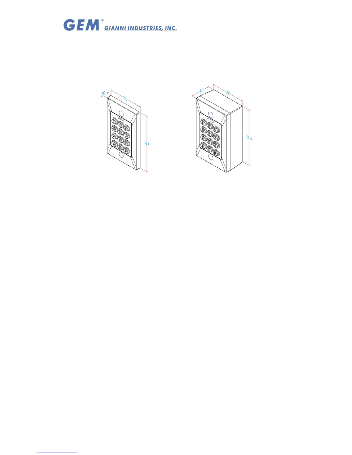
Surface mounting Installation:
SMB-750 housing is optional for
surface mount.
This series of request to exit can be
mounted directly in ANSI electrical box
(Flush mount)
Page 2
Copyright Gianni Industries, Inc. All Rights Reserved.
P-MU-DG101 Ver. B Publish:2008.10.23 Page: 2/ 3
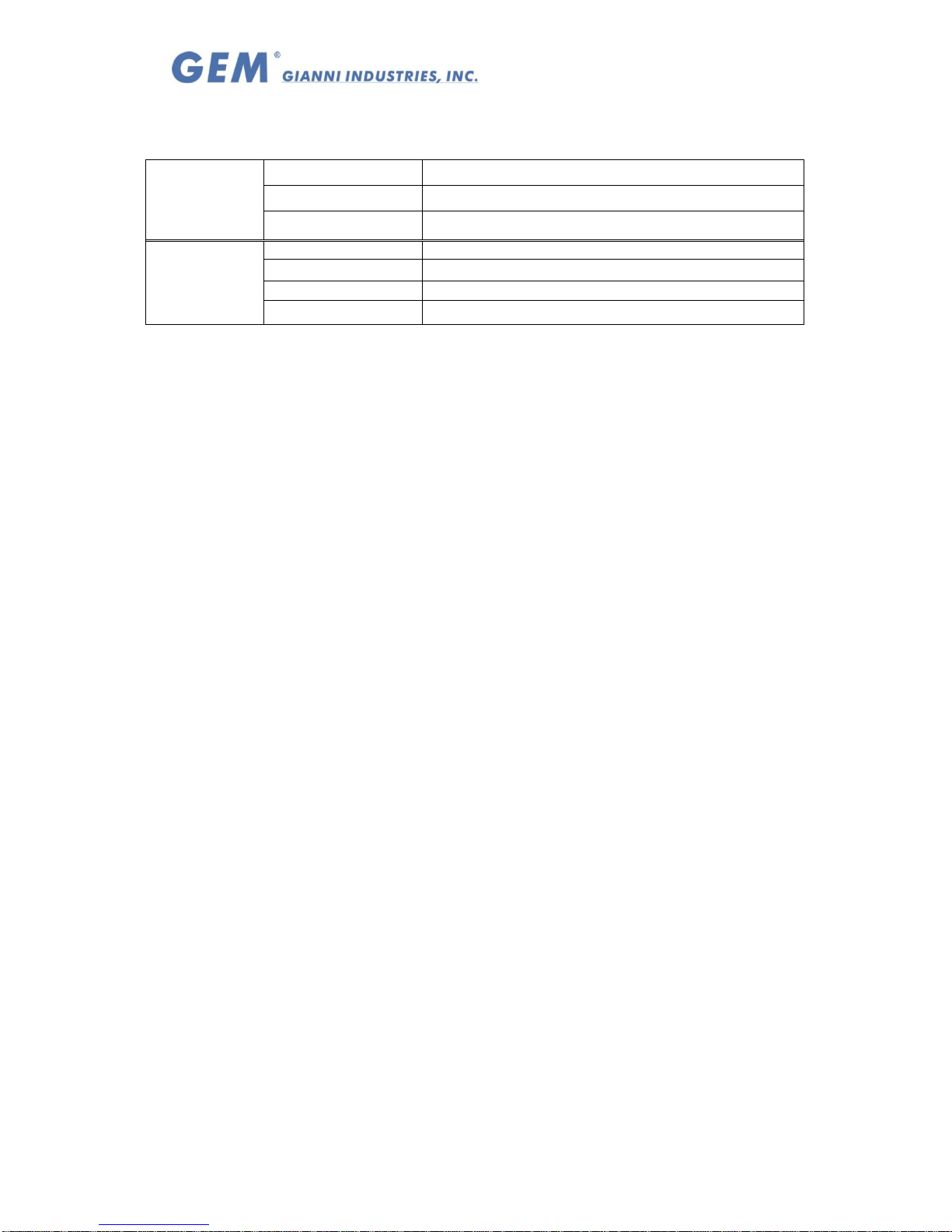
3. The indicator signal chart:
Sound and LED indicator:
Green LED Power on, stand-by
Red LED Relay 1 activated
LED signal
Yellow LED Relay 2 activated
1 Beep Effective PIN codes
2 Beeps
Entering 、Exiting from the Program mode
3 Beeps
Data computing error 、 other operation mistakes
Sound signal
5 Beeps
Master Code reset to Factory (12345)
4. Operation Instruction:
Enter Program Mode:
1. Compose twice the master code (Factory master is 「12345」)
→ 2 beeps → you are now in the "programming mode".
2. After 60 seconds if you have not entered any codes or data, the system will
automatically exit from the programming mode. After 32 wrong codes attempts at the
master code the lockout facility will operate.
Exiting from the program mode:
1. Press「#」 to exit from the programming mode.
2. After 60 seconds if you have not entered any codes or data, the system will
automatically exit from the programming mode. After 32 wrong codes attempts at the
master code the lockout facility will operate.
Add PIN codes
Enter the Programming mode, Enter the slot position code 「*001~*099」→?????
Input 5 digit PIN codes→ (beep) enrolled Æ(repeat)
Press 「#」 to exit from the programming mode, or program other operating.
Note 1: The codes「00000」,「12345」or master code are not be used for PIN code.
Note 2: Relay 1 is controlled by 001~049 user slots, Relay 2 is controlled by 050~099
user slots
To Delete a User Code:
Enter the Programming mode→ Press the slot position code of your choice to delete
(example "06") →Press「*006」→「00000」→(beep)→delete→Press「#」 to exit
from the programming mode, or programming other operating.
To Program Relocking Timer
Enter the Programming mode,
A. Relay 1:Press「*100」Followed by the number of seconds the relay should
open→「05」=5 seconds(01 ~99 = seconds)→(beep)→enrolled → Press
「#」 to exit from the programming mode, or program other operating.
B. Enter「00」Sets the relay to latching mode.
(Correct code entered opens the relay,
and the relay stays open until the correct code is entered again).
C. Relay 2:Press「*200」Followed by the number of seconds the relay should
open)→「05 =5 seconds (01 ~99 = seconds). →(beep)→enrolled → Press
「#」 to exit from the programming mode, or program other operating.
D. Enter「00」Sets the relay to latching mode.
(Correct code entered opens the relay,
and the relay stays open until the correct code is entered again).
Page 3
Copyright Gianni Industries, Inc. All Rights Reserved.
P-MU-DG101 Ver. B Publish:2008.10.23 Page: 3/ 3
Changing the Master codes:
Enter the Programming mode, Enter「*000」Followed by the new 5 digit master
code→(beep)→enrolled→Enter 「#」 to exit from the programming mode, or
program other operating.
Master Code reset to Factory 「12345」
Insert the jumper P1Æ 2-3 positionÆ5 audible beepsÆReset successfulÆ Return
Insert the jumper to 2-3 position.
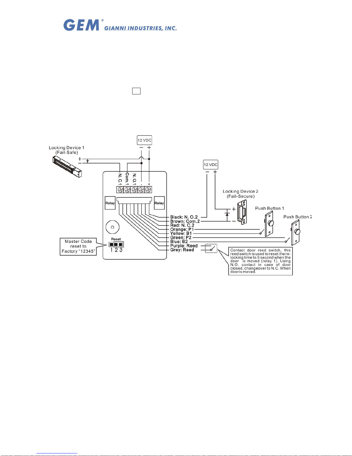
5. Wiring diagram:
Note:
The suggested wire gauge is #22~26 AWG.
The varistor or diode must be connected across the lock terminal (electromagnet...)
operated by the device. The vartistor controls the overload produced by the strike coil
(EMP).
Egresses switch should be N.O. type.
 Loading...