

Page 1
Copyright © Gianni Industries, Inc. All Rights Reserved.
P-MU-DG100-5C Ver. B Published on 2007.09.20 Page: 1/ 3
DG-100 Split Digital Keypad Entry system
Operation User's Manual (5 Codes)
1. Product Characteristic:
Allows up to 99 PIN codes
Random user codes for anti-peeping
Fully Programmable via keypad and master code
LED display with audible indication
Non-Volatile Memory
Invalid PIN Lock-out
Metal die casting housing
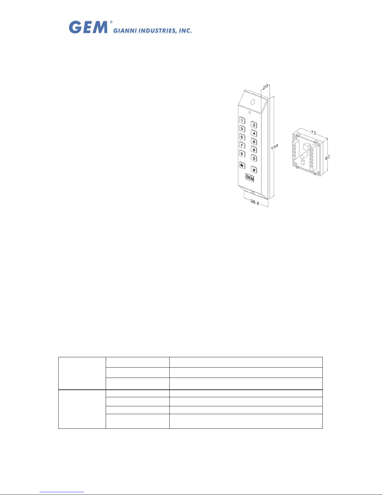
Deftly dimension for narrow jamb
With vandal resistant screws
Split of controller and reader for high security.
2. Specifications:
Operating Voltage: 12 Vdc
Current Draw: Average 15mA, Peak 70mA @ 12Vdc
Output: N.O./N.C./Com. Output (free voltage contact)
Relays Rated: 2A MAX @30Vdc ;0.4A @ 120Vac
Relay Activation Time: (*100)
Strike Time: 1~99 seconds(adjustable)
Strike mode: Access Timer or Latch
PIN codes: 5 digit codes
User codes capacity: 99 slots
Operating Temperature: -20~+70℃
Ambient Humidity: 5~95% relative humidity non-condensing
Factory Master Code: 12345
Invalid PIN Lock-out: The system will shut down for 60 seconds while 30 codes of
incorrectly Master Codes enrolled or PIN codes attempted(None beeper signal of
keypad activations).
EPROM: Non-volatile memory, System will retain all programs and codes after a total
loss of power.
Color: Beige White
Distance between the keypad and controller board: Maximum 50 M (cable#22~26 AWG).
3. The indicator signal chart:
Sound and LED indicator:
Green LED Relay activated
Red LED Power on, stand-by
LED signal
Yellow LED Programming mode
1 Beep Key-in, Effective PIN codes
2 Beeps
Entering 、Exiting from the Program mode
3 Beeps
Data computing error 、 other operation mistakes
Sound signal
5 Beeps
Master Code reset to Factory (12345)or remove all
stored user codes
Page 2

Copyright © Gianni Industries, Inc. All Rights Reserved.
P-MU-DG100-5C Ver. B Published on 2007.09.20 Page: 2/ 3
4. Default Setting:
Master code 12345
Relay time 5
Pressed key delay 30 seconds
Setting mode delay time 50 seconds
5. Operation Instruction:
Enter Program Mode:
1. Compose twice the master code (Factory master is 「12345」)
→ 2 beeps → you are now in the "programming mode".
2. After 50 seconds if you have not entered any codes or data, the system will
automatically exit from the programming mode.
3. After 30 wrong codes attempts at the master code the lockout facility will operate.
Exiting from the program mode:
1. Press「#」 to exit from the programming mode.
2. After 50 seconds if you have not entered any codes or data, the system will
automatically exit from the programming mode.
3. After 30 wrong codes attempts at the master code the lockout facility will operate.
Add PIN codes
Enter the Programming mode, Enter the slot position code 「*001~*099」→?????
Input 5 digit PIN codes→ (beep) enrolled Æ(repeat)
Press 「#」 to exit from the programming mode, or program other operating.
Note 1: The codes「00000」,「12345」or master code are not be used for PIN code.
Note 2: Random user codes operate open door:「???????????????????????? **
***」,「???….」random codes,「*****」5 digit user codes. (Random codes
and correct user codes total 29 digits.)
To Delete a User Code:
Enter the Programming mode→ Press the slot position code of your choice to delete
(example "06") →Press「*006」→「00000」→(beep)→delete→Press「#」 to exit
from the programming mode, or programming other operating.
To Program Relocking Timer
Enter the Programming mode,
A. Relay:Press「*100」Followed by the number of seconds the relay should
open→「05」=5 seconds(01 ~99 = seconds)→(beep)→enrolled → Press
「#」 to exit from the programming mode, or program other operating.
B. Enter「00」Sets the relay to latching mode.
(Correct code entered opens the relay,
and the relay stays open until the correct code is entered again).
Changing the Master codes:
Enter the Programming mode, Enter「*000」Followed by the new 5 digit master
code→(beep)→enrolled→Enter 「#」 to exit from the programming mode, or
program other operating.
Master Code reset to Factory 「12345」
Insert the jumper RESETÆ 1-2 positionÆ5 audible beepsÆReset successfulÆ Return
Insert the jumper to 2-3 positions.
Page 3
Copyright © Gianni Industries, Inc. All Rights Reserved.
P-MU-DG100-5C Ver. B Published on 2007.09.20 Page: 3/ 3
Master Code reset to Factory 「12345」 and Delete All User Codes
Insert the jumper RESETÆ 1-2 positionÆ5 audible beepsÆReset Master Code
successfulÆ (after 5 seconds) Æ5 audible beepsÆDelete All User CodesÆ Return
Insert the jumper to 2-3 positions.
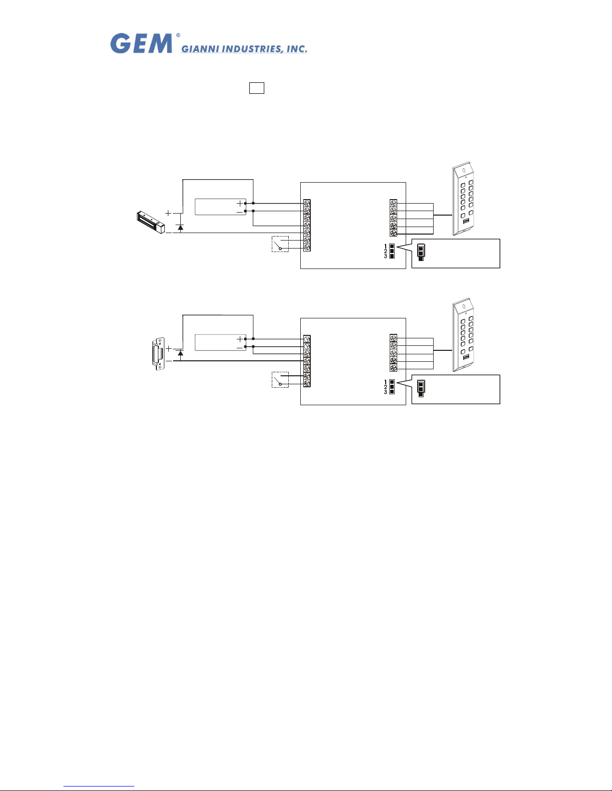
6. Wiring diagram:
+
N.O.
COM
N.C.
P
P
-
+
N.O.
COM
N.C.
P
P
-
PB
+
RC
R
-
PB
+
RC
R
-
Blue
Red
Black
White
Green
Blue
Red
Black
White
Green
Reset
Reset
Vou t
Vou t
Vin
Vin
Fail-Secture
Lockin g Device
Fail-Safe
Lockin g Device
Power Supply
Push Button
1
2
3
1
2
3
Reset to
Factory, or remove all
stored .
Master Code
PIN codes
Reset to
Factory, or remove all
stored PIN code s.
Master Code
Power Supply
Push Button
Note:
The suggested wire gauge is #22~26 AWG.
Distance between the keypad and controller board: Maximum 50 M (cable#22~26 AWG).
The varistor or diode must be connected across the lock terminal (electromagnet...)
operated by the device. The vartistor controls the overload produced by the strike coil
(EMP).
 Loading...