

Page 1
1
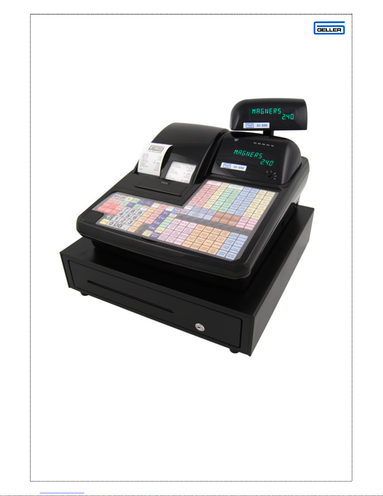
SX-590
SX-590 QUICK SET -UP GUIDE
Page 2

2
SX-590 QUICK SET -UP GUIDE
For further information please refer to the standard
Operating Manual supplied with the SX-590
SX-590 *Features*
ü 99 Departments & 8000 PLUs from standard
ü 58mm Receipt & Journal Printers
ü 5 Server Holds With Auto Store (Optional Pre Set Time Limit)
ü PC Link (Geller David Utility Available) with Pre-Installed Demos
(Bar, Retail/Scanning and Fish/Chip Demo)
ü Scanning with Barcode Auto Search, Price Check & Plu Delete Features
ü Drawer Alarm with programmable timer & Money Lift Alarm
ü Soft Keyboard Layout
ü PLU Shift system, Half Pints, Doubles, Glass etc
ü Quick tender keys (£5, £10, £20 & £50) for fast tendering
ü Easy Price & Name Change
ü Training Mode
ü Compulsory Cash Declaration X & Z
ü Multiple scrolling display messages
ü Graphic Logo
ü Euro Settings
ü Optional Totals only on Journal
ü UK Receipt Format, Including 4 Digit Time And Date Format
ü Negative Items
ü Passwords for Management Control
ü Management reports
Page 3

3
INDEX
DESCRIPTION Page
QUICK SET-UP GUIDE 1
SX-590 Features 2
PAPER ROLLS 5
Installing the Paper Rolls 5
Installing the Paper Roll for the Receipt 6
Installing the Paper Roll for the Journal 6
Removing the Paper Rolls 7
SX-590 INITIALISING 8
PROGRAMMING TIPS 9
To chec k the flash version in the SX-590 9
DATE & TIME SETTINGS 10
Setting the Date 10
Setting the Time 10
PROGRAMMING INFORMATION – SX-590 ECR 11
Programming keyboard layout 11
FLAG SET -UP PROCEDURE 12
PLU SETTINGS, SHIFTS, QUICK TENDERS & TAX RATES 13
Easy PLU Price & Name Change 13
HALOS and Preset PLU Prices 13
PLU Shifts (Half and Doubles etc) 14
Quick Tender Keys (£5, £10, £20, £50) 15
Totals Only on Journal Report 15
Tax Rates 16
ADDITIONAL INFORMATION 17
To Set the Drawer Alarm Delay 17
To Set the Clerk Hold Timer 17
To Set the Cash Lift Alarm 17
PASSWORDS 18
Setting Secret Clerk Passwords 18
Setting Management Passwords 18
PC COMMUNICATIONS 19
Downloading a Demo to the SX-590 ECR 19
SX-590 DAVID WINDOWS UTILITY 20
SX-590 DAVID SALES UTILITY 21
CABLE CONFIGURATION 22
Pin Outs for SX-590 to PC Communications Cable 22
Pin Outs for SX-590 Modem to SX-590 Communications Cable 22
Pin Outs for the Elco Switch Multiplexor Direct to SX-590 23
Pin Outs for the Elco Switch Multiplexor via the Hayes Modem 23
CONFIGURING MODEM SETTINGS 24
Modem Settings for the Geller Modem (Hayes) 24
Connecting the Modem to a PC 24
Page 4

4
MULTIPLEXOR ELCO SWITCH CONFIGURATION 25
GRAPHICAL LOGO FOR SX-590 26
Creating the Graphical Logo 26
Downloading Logo to ECR 26
SCANNING CONFIGURATION 27
ADDING A PLU BARCODED ITEM TO THE ECR 28
Updating the Price/Name of Previously Scanned Products 28
SCANNING UN-PROGRAMMED PRODUCTS IN THE ‘R’ POSITION 29
Deleting a Previously Scanned Product 29
BAR CODES SAMPLE 30
EURO SET-UP 31
REPORTS 32
Displaying a Report 32
GLOSSARY 33
DEPARTMENT 33
PLU 33
HALO 33
PRICE OVERRIDE 33
CASH, CHEQUE AND CARD 34
CLERK ID 34
CLERK HOLD 34
#/ST 34
TOTAL 34
X-TIME 35
FC 35
RA 35
CANCEL 35
EC 36
VOID 36
RETURN 36
DISCOUNT (-Key) 36
% Discounts 36
FLAGS 37
INITALISE 37
SYSTEM CLEAR 37
Page 5
5
PAPER ROLLS
INSTALLING THE PAPER ROLLS
Your cash register features a thermal printer which uses two rolls of 58mm standard
bond paper; one roll (left side) is for the customer receipt and the other roll is for the
journal record (right side). If a customer receipt is not required, a paper saving
option is available by pressing the [ON/OFF] key on the keyboard.
Before installing the paper roll, be sure to do the following to avoid causing a
paper jam:
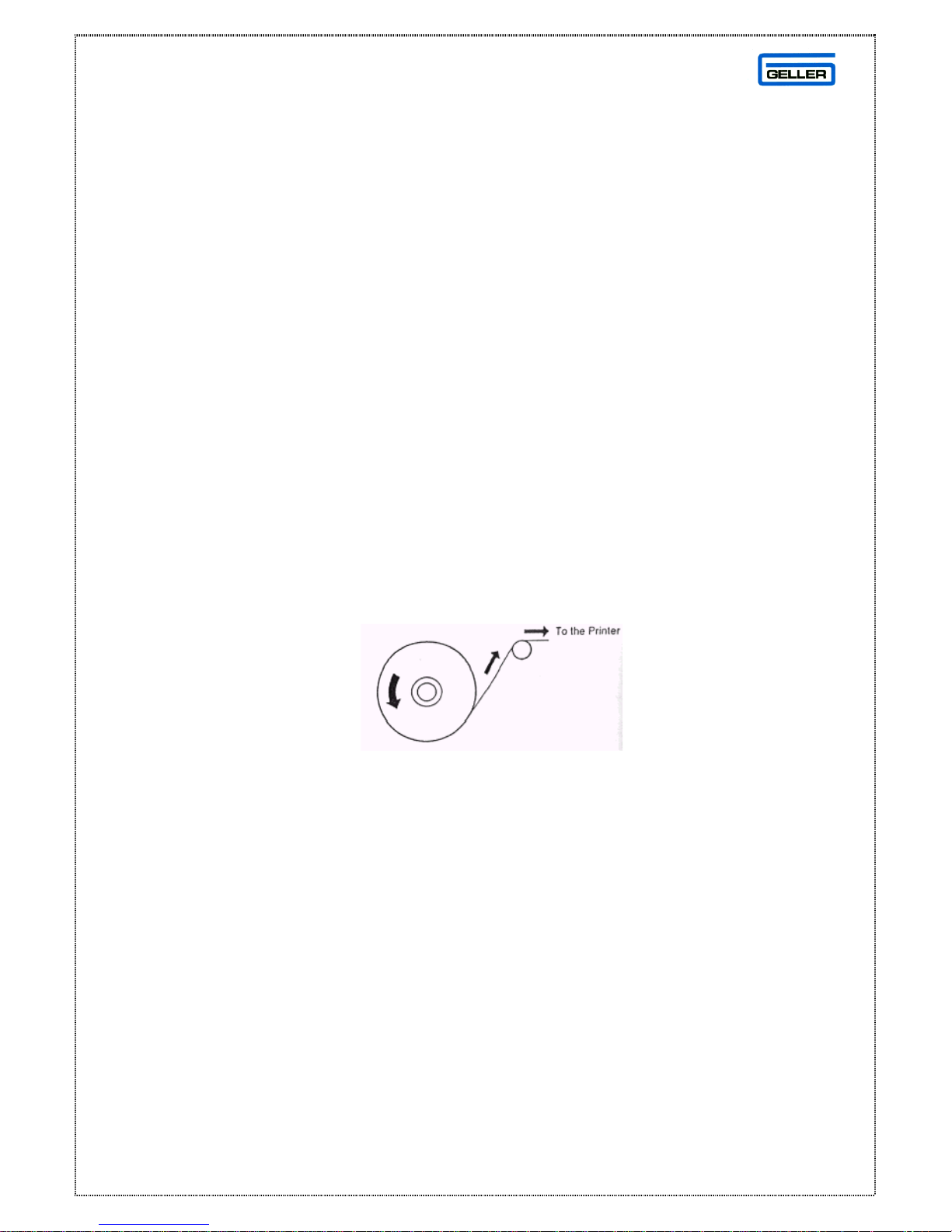
Orient the paper roll so that it rotates in a counter clockwise direction, as shown in
fig 1.
Fig 1
Note
1. As thermal paper is used, it has a right and wrong side for print. Install the
paper roll correctly
2. Carefully avoid touching the paper cutter when removing the paper cover.
CAUTION: If a paper jam occurs or a paper roll is used up during print, please
install a new paper roll and press the [ENT RLS] key to release.
Page 6
6
Installing the Paper Roll for the Receipt
1. From the front of the cash register, hold onto the rear of the printer cover and
lift it up
2. Push the platen release button (left) to raise the paper guide
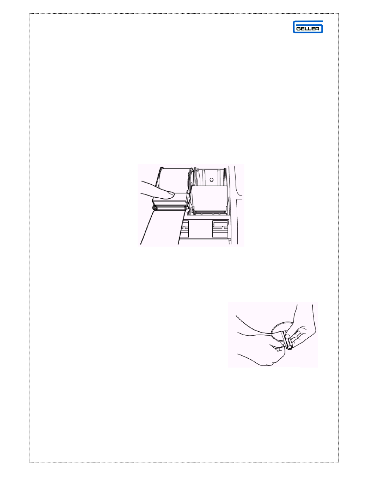
3. Load the paper roll into the receipt location, and put the paper end to this side
4. Depress the paper guide (see fig 2)
5. Keep the paper guide to this end and close the printer cover
Fig 2
Installing the Paper Roll for the Journal
1. Make sure the Control Lock is in the ‘R’
(Register) position
2. From the front of the cash register, grab the
rear of the printer cover and lift it up
3. Push the platen release button (right) to raise
the paper guide
4. Load the paper roll into the journal location, and put the paper end to this side
5. Depress the paper guide
Fig 3
Page 7
7
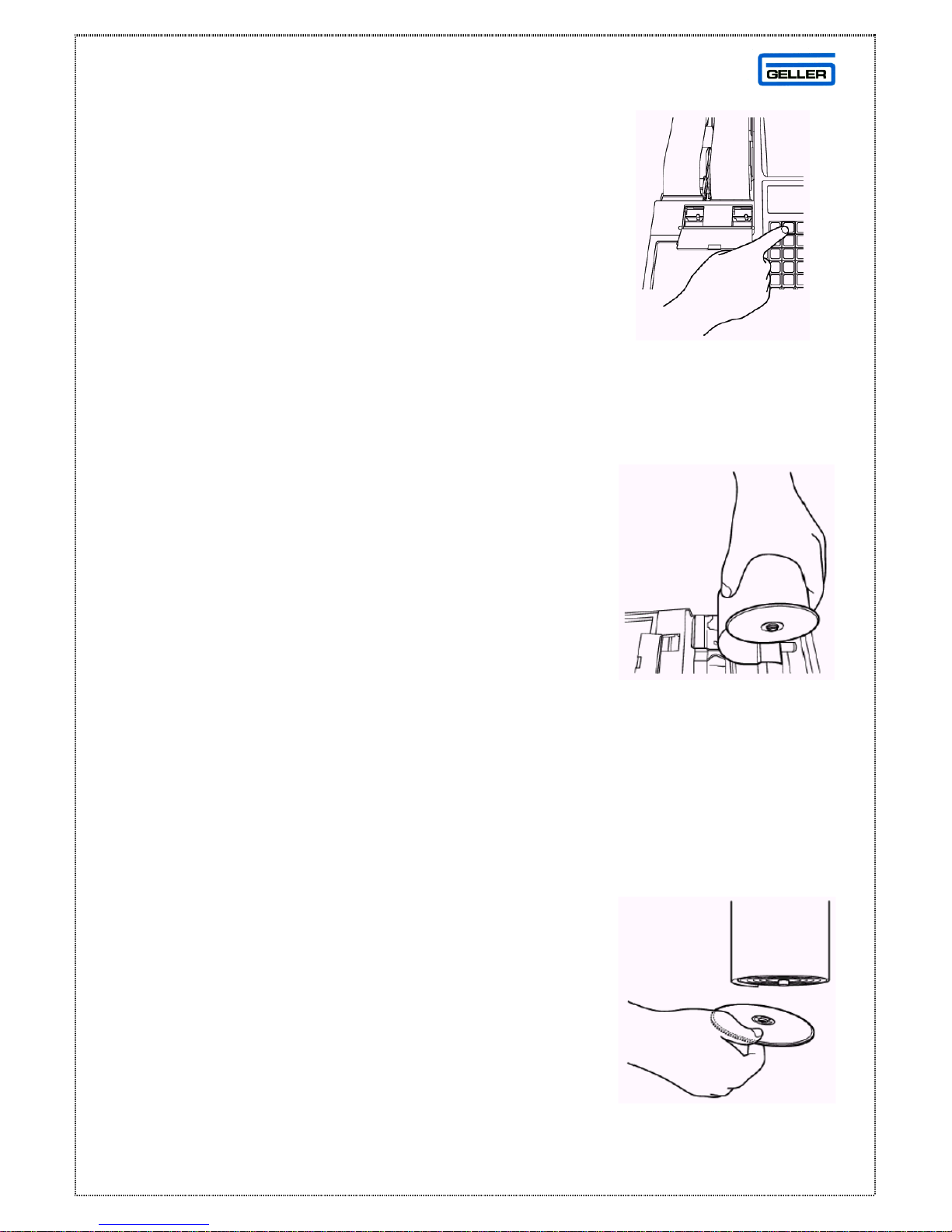
6. Insert the end into the slot in the take-up reel and
wind two or three turns of paper around the reel
(See fig 3)
7. Load the take-up reel into the support
8. Press the ‘J’ feed key (See fig 4)
9. Close the printer cover
Removing the Paper Rolls
To remove the paper roll for the receipt
1. Open the printer cover
2. Push the platen release button (left)
3. Remove the roll
To remove the paper roll for the journal
1. Open the printer cover
2. Push the platen release button (right)
3. Cut the paper after the end of the printing
4. Remove the take-up spool from the support (See fig 5)
5. Remove the paper record for the take- up reel (See fig 6)
6. Install the remaining paper for the journal
7. Close the printer cover
Fig 4
Fig 5
Fig 6
Page 8

8
SX-590
INITIALISING
WARNING
This procedure will clear all sales data and program settings
• Turn off the power at the mains (Or side switch)
• Turn the key to the ‘P’ position with the ‘MA’ Key
Hold down the ‘CLR’ key and power on the ECR.
Release the ‘CLR’ key after 10 Seconds. The message ‘SYSTEM CLEAR’ will
appear on the display. The ECRs memory has now been RAM CLEARED
Page 9
9
PROGRAMMING TIPS
To check the Flash Version in the SX-590 do the following –
• Turn the key to the ‘P’ position on the Control Lock
• Turn off the power at the mains (Or side switch)
• Press and hold the CASH key
• Power on the ECR
A ticket will be printed from the cash register. At the bottom of the ticket will be
the Flash Version that is currently installed on the Cash register
Example – SX-590 V.AE
For Upgrading Flash or Updating Boards
Please Contact our Support Department
The following table contains information on printing program confirmation.
Please note all of the following are performed in the ‘P’ Position
Confirmation Type Procedure
Program Confirmation 9 9 9 9 9 9 CASH TEND
Clerk Confirmation ENT RLS - CLK ID
Dept Confirmation ENT RLS - DPT #
PLU Confirmation ENT RLS - PLU
PLU Range PLU # (1- 5000) - ENT RL S - PLU End # (1-
5000)
PLU
IMPORTANT
There are many keys which are used in the programming position. We
recommend that you leave these keys in their default positions, so not to make
this confusing for the end user. The SX- 590 does have a soft keyboard, but
when the key is turned to the ‘P’ position, the default programming keyboard is
loaded. See page 11 for the programming layout and their positions.
Page 10

10
DATE &TIME SETTINGS
Setting the Date
• Turn the key to the ‘P’ position on the Control Lock
• Enter the date (DD/MM/YYYY) press # / NS
Example 20032008 = 20th March 2008
Note:
The # / NS key must be the default button which can be found on the
standard programming layout.
Setting the Time
• Turn the key to the ‘P’ position on the Control Lock
• Enter the time (HH/MM) press X TIME
Example 1300 = 1 PM in 24 Hour Format
Note:
The # / NS key must be the default button which can be found on the standard
programming layout.
To check the time turn to the ‘R’ position and press the X/TIME key. The
time is displayed in the bottom right hand corner of the display.
Page 11
11
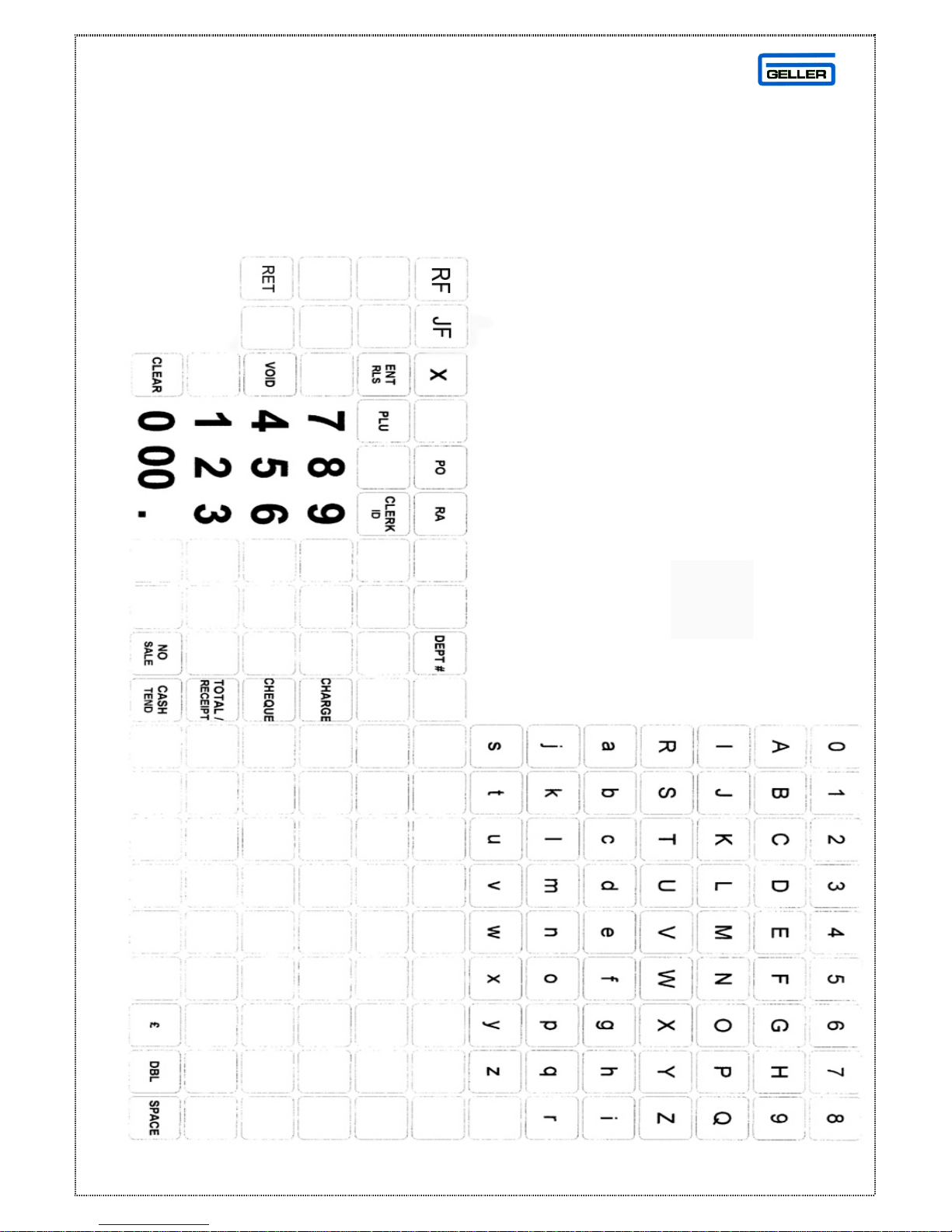
PROGRAMMING INFORMATION
This is the programming layout for the SX-590 Flat ECR
Page 12

12
FLAG SET -UP PROCEDURE
The following flag se ttings will configure your SX-590
for a basic demonstration system, see below -
• Turn the key to the ‘P’ position on the Control Lock
• Enter the Flag Number followed by the setting required and press
VOID
Example to set Flag 1 = 2 (Press - 1 - 2 - VOID)
Note:
The # / NS key must be the default button which can be found on the standard
programming layout.
FLAG 1 = 2 - Date Format
FLAG 2 = 1 - Time Format
FLAG 3 = 2 - Decimal Point
FLAG 5 = 5 - Rounding Format
FLAG 26 = 1 - Enable PC comms for Graphic Logo
FLAG 27 = 1 - Simultaneous print mode for Receipt
FLAG 28 = 1 - Simultaneous print mode for Journal
FLAG 93 = 1 - Drawer Closed compulsory
For additional flags, please consult the manual
supplied with the machine.
Page 13

13
EASY PLU PRICE & NAME CHANGES
EASY PLU PRICE CHANGE
• Turn the key to the ‘P’ position on the control lock
• Enter the PLU Number and Press the PLU key
• Enter the Price and Press the DEPT# key
EASY PLU NAME CHANGE
• Turn the key to the ‘P’ position on the control lock
• Enter the PLU Number and Press the PLU key
• Press DEPT# and type in the name using the Alpha Keys
• Press the CHEQUE key
Note: For Scanned items please see Page 28
HALOS AND PRESET PRICES
The SX590 can have HALOs and Preset prices. These are controlled by the
Dept Flags and the PLUs which are linked to them.
Dept Flag Bit 3 Controls the preset price, and Dept Flag bit 8 controls the Halo
Page 14

14
PLU SHIFT FEATURE
HALF PINTS / DOUBLE Etc..
The SX590 can now per form PLU shifts allowing you to do popular functions
such as Half Pints, Doubles, Large Glasses of Wine etc. The multiplier
function will also work with this feature.
The First PLU Shift Range is 1 – 200. Once the PLU Shift key is pressed the
PLUs are shi fted to a PLU range of 201-400
Example PLU1 = Fosters PLU 201 = Half Fosters
The Key code for PLU Shift is 062
Two Main Flags have been added for the PLU Shift System
MF 112 bit 1 = 0 (PLU Shift Stays down for one Item)
MF 112 bit 1 = 1 (PLU Shift Stays down Always until the Shift key is pressed
again)
Note: For Half Pint function Please also ensure MF 115 bit 1 = 1
Page 15

15
QUICK TENDER KEYS
The SX590 has 4 keys to allow a quick payment of a transaction.
£5.00, £10. 00, £20.00 and £50.00
Keycode 072 = £5.00 Tender
Keycode 073 = £10.00 Tender
Keycode 074 = £20.00 Tender
Keycode 075 = £50.00 Tender
Please Note: Ensure MF 116 Bit 1 = 1
TOTALS ONLY ON JOURNAL PRINT
The SX590 has an option for totals only on the Journal Print. By
setting a flag you can toggle between an itemised journal which
will print all of the products registered or totals only which will print
just the total of the transaction
MF 113 Bit 1 = 1 (Totals Only Enabled)
MF 113 Bit 1 = 0 (Totals Only Disabled)
Page 16

16
PROGRAMMING TAX RATES
Programming a Vat Inclusive value to Department 1
• Turn the key to the ‘P’ position on the Control Lock
• Press 1 1 followed by the Charge Key
• Enter the Tax rate 175000 followed by the TOTAL key
• Press the No Sale key
• Link Tax rate 1 to Dept 1 by pressing 1 TOTAL 0 ENT RLS
• Enter (Required Dept Number) 1 followed by the DPT # key
Note: The Tax value for a Sale of £1.00 should be 0.15p
Programming Add on Vat to Department 1
• Turn the key to the ‘P’ position on the Control Lock
• Press 1 0 followed by the Charge Key
• Enter the Tax rate 175000 followed by the TOTAL key
• Press the No Sale key
• Link Tax rate 1 to Dept 1 by pressing 1 TOTAL 0 ENT RLS
• Enter (Required Dept Number) 1 followed by the DPT# key)
Note: The Tax value for a Sale of £1.00 should be 0.18p
Please Set MF 5 = 5 For Tax Rounding
Page 17

17
ADDITIONAL INFORMATION
To Set the Drawer Alarm Delay
• Turn the key to the ‘P’ position on the Control Lock
• Press 5
• Enter the number of seconds required for the delay
Ie 10 for ten seconds
• Press the PO key (The PO must be the default button).
To Set the Clerk Hold Timer
The SX590 can store an opened clerk after a pre-programmed time
delay.
• Turn the key to the ‘P’ position on the Control Lock
• Press 7
• Enter the number of seconds required for the delay
• Ie 10 for ten seconds
• Press the PO key (The PO must be the default button).
To Set the Cash Lift Alarm
When the cash in the drawer exceeds the pre-programmed limit ‘LIFT’ is
displayed.
• Turn the key to the ‘P’ position on the Control Lock
• Press 6
• Enter the amount of money required for the cash lift limit
Ie 00050000 for five hundred pounds
• Press the PO key (The PO must be the default button).
Note: A Cash Dump can be made by using the PO Key
Page 18

18
PASSWORDS
Setting Secret Clerk Passwords
A maximum of 40 different clerk passwords can be set, which allow clerks to
operate the ECR in the ‘R’ position.
• Turn the key to the ‘P’ position on the Control Lock
• Enter 4 4 4 4 4 4 and press the CASH key
• Enter the desired clerk number
(Note for Clerk 1- 9, enter the 0 ie 01 for clerk 1)
• Enter up to 4 digit password and press the CLK ID key
Setting Management Passwords
There are two manager passwords which are available for security measures.
One password accesses P/Z mode and the other accesses the X mode
To Program the X Manager Password
• Turn the key to the ‘P’ position on the Control Lock
• Enter 2 2 2 2 2 2 and press the CASH key
• Enter the desired 4 digit Manager Password
• Press the TOTAL key
To Program the X Manager Password
• Turn the key to the ‘P’ position on the Control Lock
• Enter 1 1 1 1 1 1 and press the CASH key
• Enter the desired 4 digit Manager Password
• Press the TOTAL key
Note:
To use the managers’ passwords, turn to the relevant position on the control
lock, enter the manager password and press the CLERK ID key
Page 19

19
PC COMMUNICATIONS
The SX-590 has the capability to read / send programming & sales data from a
Personal Computer. The SX-590 Windows utility is available on CD and can
also be upgraded from our web site www.geller.co.uk
The utility has 3 demo programs for your use.
• SX-590 Bar Demo
• SX-590 Retail Demo
• SX-590 Fish & Chips Demo
The relevant files for printing the Keyboards for these demos are pre-loaded in
the SX-590 windows utility.
Downloading a Demo to the SX-590 ECR
Note:
The PC Comms Port on the SX-590 are automatically configured for PC
communications after a RAM clear. To manually access the communications
setting -
• Turn the key to the ‘P’ Position on the control lock
• Set the Following System Flags
SF 73 = 1 PC Mode
SF 74 = 2 Even Parity
SF 75 = 0 9600 Baud Rate
SF 76 = 1 8 Bit data
• Insert the Communications cable into the por t on the side of the SX-590
labelled (COM A)
• Perform a Loop Reset (Turn the key to the P position, Power off the ECR,
wait 30 Seconds, Power on the ECR)
Page 20

20
GELLER SX-590 WINDOWS UTILITY
• Insert the CD into your PC and follow the standard Windows on screen
instructions
to install the program
• Run the Utility program
• Select the desired demo program
• Click Send Details
• Click button (select all items)
• Click (Send Till)
• The program will now be sent to the SX-590
• Once the progam has fully downloaded, Perform a Loop reset on the SX-590
(Turn the key to the P position, Power off the ECR, wait 30 Seconds, Power
on the ECR)
Page 21

21
SX-590
SALES UTILITY
DAVID SX-590 KEY BENEFITS
• Windows operating system
• Program all important aspects of the ECR ie PLUs, Depts, Clerks, Keyboard,
Receipt & Graphic logo
• Multiplexor support with multiple Read / Send
• Modem Support
• Create customer keyboard template within David. (Copy Buttons, indexes and
picture functions all included
• Configure user options within David using the Hot pad function giving
management control
• Administrators password for full access
• Read sales from the ECR into David
• Multiple reports for sales and management including graphs
• Accumulated reports
• Purge (Delete) reports
• Scheduler report system (Ability to read reports from the ECR at the date / time
of your choice
• Scheduler programming (as above but the ability to read / send programming
data
• Edit and Read/send Graphic Logo in ECR
Note: Please contact our support department for further information
Page 22

22
CABLE CONFIGURATION
Pin Outs for SX-590 to PC Communications Cable
The cable used for communication is a straight through RJ45 lead connected to
an Adapter 11 (SX-590) (see below for Pin Outs)
9 Way Female
Adaptor 11 (SX- 590)
2 - Orange
3 - White
4 - Brown
5 - Red
6 - Green
7 - Black
8 - Blue
Pin Outs for SX-590 HAYES MODEM to SX-590 Communications
Cable
The cable used for Modem communication is a straight through RJ45 lead
connected to an Adapter 12 (SX-590 Modem) (see below for Pin Outs)
25 Way Male 25 Way Male
Adaptor12 (SX- 590 Modem) Adaptor12 (SX-590 Modem)
RJ45 25WAY
2 - Orange 1 4
3 - White 2 2
4 - Blue 3 5
5 - Black 4 7
6 - Brown 5 20
7 - Red 6 N/C
20 - Green 7 6
8 3
Note: For Modem Configuration, please see page 24
Page 23
23
CABLE CONFIGURING Cont…
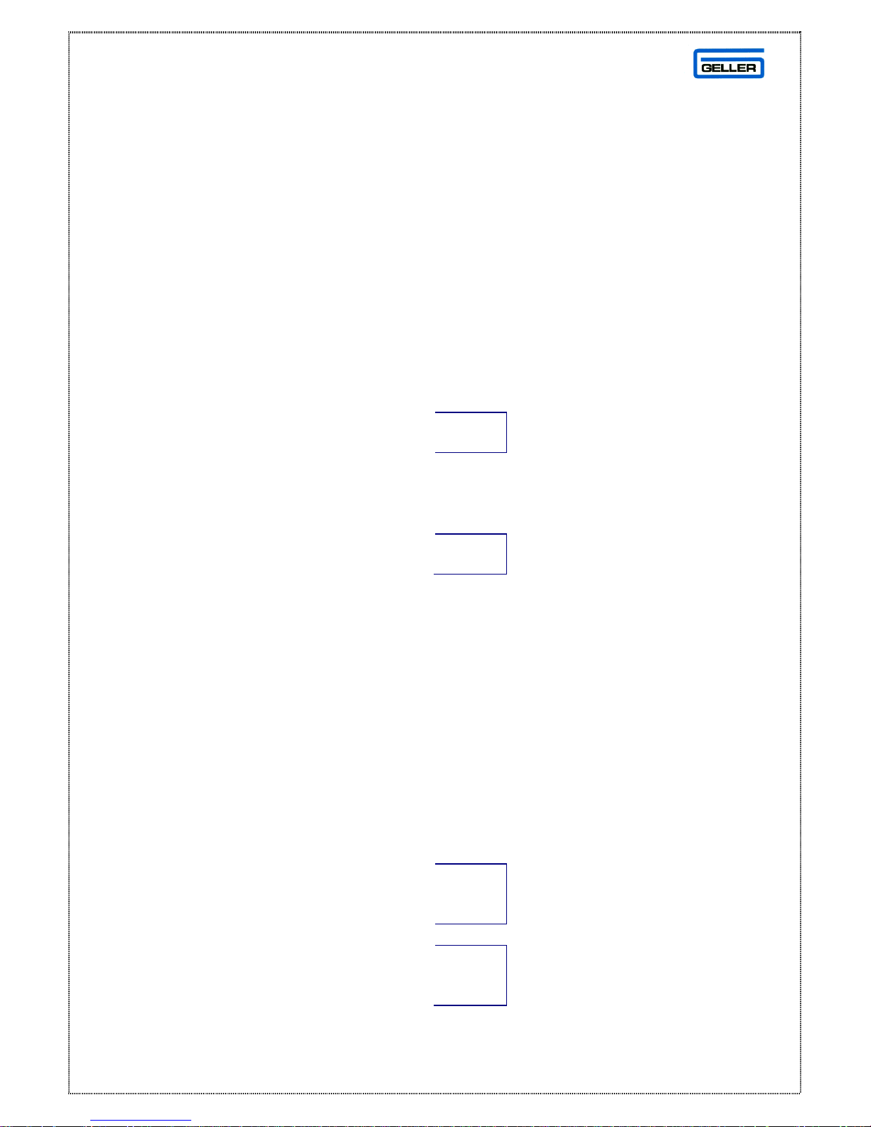
Pinouts for the Elco Switch Direct to SX-590
PC MUX Input
ADP 1 (9 way female) ADP 6 (9 way female)
1 – NA 6 - Red 1 – N/A 6 - Orange
2 – Brown 7 – Yellow 2 – Blue 7 - White
3 – Blue 8 – White 3 – Brown 8 - Yellow
4 – Orange 9 – N/A 4 – Red 9 – N/A
5 -- Green 5 -- Green
MUX Output
ADP 14 (9 way female )
RJ45 ADP14
1 - (RTS) 8 – (CTS) Shorted
2 – (TXD) 2 – (RXD)
3 – (CTS) 7 – (RTS)
4 – (GND) 5 – (GND)
5 – (DTR) 6 – (DSR)
6 – NA N/A
7 – (DSR) 4 – (DTR) Shorted
8 – (RXD) 3 – (TXD)
Pinouts for Elco Switch Using a Modem
Modem MUX Input
ADP 8 (25 way male ) ADP 6 (9 way female)
2 - Brown 8 – Yellow 1 – N/A 6 - Orange
3 – Blue 20 – Red 2 – Blue 7 - White
4 – White 3 – Brown 8 - Yellow
6 – Orange 4 – Red 9 – N/A
7 – Green 5 - Green
MUX Output
ADP 14 (9 way female)
RJ45 ADP14
1 – (RTS) 8 - (CTS) Shorted
2 - (TXD) 2 – (RXD)
3 – (CTS) 7 – (RTS)
4 – (GND) 5 – (GND)
5 – (DTR) 6 – (DSR) Shorted
6 - N/A N/A
7 – (DSR) 4 – (DTR)
8 – (RXD) 3 – (TXD)
Page 24

24
CONFIGURING MODEM SETTINGS
For automatic configuration please use ‘GMODEM’ which is available on the
GELLER CD and GELLER Website. This is the easiest configuration method.
For manual configuration, the Geller modem should be configured as follows -
The settings must be changed using AT commands via communication software
such as Terminal, Hyper Terminal or Q modem.
To connect to one of the above windows programs, use the following attributes
9600 baud rate
8 Data Bits
1 Stop Bit
Even parity
Connecting The Modem To A PC
The AT commands to set the host modem are as follows -
AT&F0
AT&W0
AT&W1
Connecting The Modem to a SX-690
(Hayes Modem)
The AT commands to set the remote site to auto answer are as follows
AT&F0
AT&D0
ATS0=1 *(Observe note below)
ATQ1
AT&W0
AT&W1
Note:
If the modem is required to auto answer after three rings then change
ATSO=1 to ATSO=3 from the above example.
Page 25

25
MULTIPLEXOR CONFIGURATION
A multiplexor will allow you to connect multiple SX-590 Cash registers to a PC.
This is useful for programming updates & software sales reads.
IMPORTANT
When entering the Switch Port commands in the Windows Utility, please
ensure capitals are used.
i.e. ELCO2
Please Note:
To configure the new ELCO Data switch
Please refer to the new guide sheet which can be found on the Geller
Website.
Page 26

26
GRAPHIC LOGO FOR SX-590
The SX-590 has a built in Flash ty pe Graphical Eprom facility. A Graphic Logo
can be downloaded as many times as required.
The following System Flag has to be enabled.
SF 26 = 1 – This enables the Graphical logo to be sent via a PC
There is a default graphic logo within the David SX590/Logo directory which
can be used as a template
Creating the Graphical Logo
• Scan the desired logo in Black and White.
• Resize the image to 384 pixels wide, 220 pixels high
• Set the Image properties for two colours (or monochrome)
• Save the image as a BMP file
• Copy the image into the SX-590\Logos directory
Downloading Logo to ECR
Using the SX- 590 Utility, you can now select the option Graphic Logo. Within
this section, simply click on the desired logo and click Save.
Send the logo to the SX- 590
IMPORTANT
After the logo has been sent to an ECR a LOOP RESET must be performed.
Page 27

27
SCANNING
Your Geller scanner will arrive already pre-configured.
Please ensure when ordering that you state the
model of ECR your scanner is to be configured for i.e SX- 590
Plug the scanner into the labelled COM B socket on the
SX- 590 and follow the simple procedure below -
SX-590 Set-up with Scanner
Note:
The Scanner Comms Port on the SX- 590 is automatically configured for your
scanner after a RAM clear. To manually access the communications setting -
• Turn the key to the ‘P’ Position on the control lock
• Set the Following System Flags
SF 77 = 0 Scanner Mode
SF 78 = 2 Even Parity
SF 79 = 0 9600 Baud Rate
SF 80 = 0 7 Bit data
• A Loop reset must be performed
Page 28

28
ADDING A PLU BARCODED ITEM
TO THE ECR
• Turn the key to the ‘P’ position on the control lock
• Scan the Bar Code (This will automatically select the next available
PLU Number)
• Enter the Price and press ENT / RLS
• Enter the DEPT link number and Press DPT#
• Using the Alpha keyboard type in the name of the product
• Press the CHKS / STUB
• Repeat until all required products are scanned
Updating Prices of Previously Scanned Products
• Turn the key to the ‘P’ position on the control lock
• Scan the previously programmed scanned product
• Enter the new price and press the DPT# key
Updating Names of Previously Scanned Products
• Turn the key to the ‘P’ position on the control lock
• Scan the previously programmed scanned product
• Press the DPT# Key and type in the name of the product
• Press the CHEQUE key
Note: To link the PLU to a different Dept Link, simply press the Department
key of your choice instead of the DPT# key
Note: To search for a vacant PLU number, Turn to P and press 0 PLU
To program the starting PLU allocation number, Turn to P and press 8 (starting
number 1- 8000) PO key
Page 29

29
SCANNING UN-PROGRAMMED PRODUCTS
IN THE ‘R’ POSITION
• Scan the Un-Programmed product
• The user is Prompted “Price”
• Enter the Price and press ENT / RLS
• Enter the DEPT link number and press the Dept # Key
• Finalise the sale
Note:
The department name is used for the product.
See page 28 for changing the name of the product
Deleting a Previously Scanned Product
• Turn the key to the ‘P’ position on the control lock
• Scan the product that requires deleting
• Press ENT / RLS
• Press 0 then the DPT # key
• Press NO SALE
• The product is deleted from the cash register
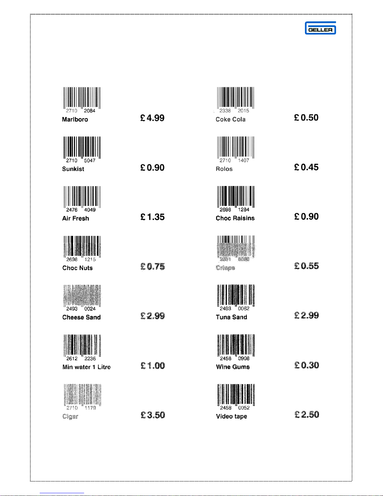
We have included some sample Barcodes overleaf for you to use for
demonstrations. These are pre-configured on the demo programs within the
Geller Windows utility
Note:
The Price Key (Code 057) can be used as a price check key
Page 30
30
BAR CODES SAMPLE
Page 31

31
EURO SET -UP
The following settings will configure the SX- 590 for the EURO Function
• Put Euro Key on keyboard (Key Code 68)
Work out Euro Conversion Rate e.g if the Euro is 1.64 to the pound
then do the following:
• 1 - Divided by - 1.64 = 0.6097
• 0.6097 would be the Figure to enter into the ECR’s Currency rate
• Turn the key to the P position on the control lock
• Enter 9 1 2 (enter rate ie 0.6097) Press the PO key
Note:
When entering the rate into the ECR, the decimal point must be used.
The following example shows a transaction that is tendered as EURO
In the Register position
1.00 DPT 1 - Press Euro - Press Cash
Note:
From Default the Change will be given in Local Currency.
Page 32
32
REPORTS
Displaying a Report
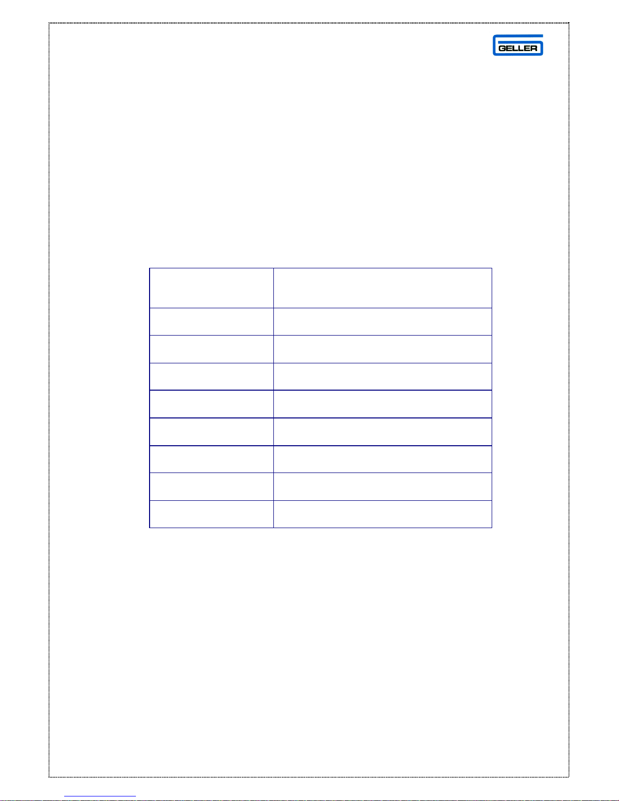
It is possible to have the report of your choice displayed on the SX-590.
This will be an X Report so that it is impossible to accidentally reset the
report without printing it
• Turn the key to the X Position on the Control Lock
• Use the following table to select the report
To Display
Press the following keys in the “X”
position
Net total 1 XTIME
Cash total 2 XTIME
Charge total 3 XTIME
Cheque total 4 XTIME
No Sales total 5 XTIME
RA total 6 XTIME
PO total 7 XTIME
Cash in Drawer 8 XTIME
The most standard and popular reports are the Transaction, PLU and Clerk
reports. Here are a list of other reports the SX-590 has to offer
• Hourly Report
• Cash Declaration Report
• Group Report
• Individual Clerk Report
• PLU Range Report
• Grand Total Report
Page 33

33
GLOSSARY
The following list describes the SX- 590’s
general terms and explanations for the
functionality of the machine
DEPARTMENT
A department can be used for grouping purposes. When a product is sold,
it will report under the heading of the designated department that the
product is linked to ie Stationery. Departments can also be placed on the
keyboard for manual price entry. Key in the amount and press the
relevant Department key
PLU
PLU stands for Price Look Up. These are the actual products that are sold
on the cash registers ie Pen, Pencil. The PLU must be linked to a
Department category to function.
HALO
HALO stands for High Amount Lock Out. This allows the user to program a
limit for each PLU/DEPT. ie An amount of no more than 10.00 can be
entered or sold for a designated product
PRICE OVERIDE
The Price Override feature allows the user to override the pre- set price of a
product. Key in the amount and sell the desired PLU
CASH, CHEQUE AND CARD
After items have been registered, a method of payment can be selected.
The amount of money given by th e customer can be entered and the
change given will be displayed
The totals report as cash in drawer, cheque in drawer and card in drawer.
These will all add up to the net total when a report is taken.
Page 34

34
CLERK ID
Each user (Clerk) can have their own unique password for operating the
Cash register. This is useful for security and for reporting purposes. The
Clerk ID key can also be used to toggle the receipt on and off.
CLERK HOLD
This will allow a clerk to hold their sale in the ECR while another Clerk
carries out a transaction.
Example:
Sign on the Clerk, register some items and press the Hold key. The sale is
stored in the cash register and the Display will show which clerks have
outstanding sales.
There are a maximum of 5 clerk holds on the Cash register.
# / ST
The # key is the function for No Sale. This will open the drawer.
The ST key is the function for Sub Total. After registration of a few
products, the Sub total key when pressed will display the total amount due
and print on the receipt.
TOTAL
The total key is used to display the total amount due including any add on
taxes.
The Total key is also used for printing a receipt after sale.
Page 35

35
X- TIME
The X- Time key is used for multiplication.
Example:
2) (X/TIME) (1.00) (DPT 1) would register a sale of 2.00 in Dept 1.
The key is also used for displaying the current time on the display
FC
The FC key is used for tendering in a foreign currency for example the
Euro.
RA
The RA key is the function for Received on Account. An amount that is
entered into the RA key as cash will increase the cash in drawer. A popular
use for this function would be to pay in a float.
Example:
Enter Amount – Press RA – Press Cash
PO
The PO key is the function for Paid Out. An amount that is entered into the
PO key as cash will decrease the Cash in drawer. A popular use for this
function is a Float out system.
Example:
Enter Amount – Press PO – Press Cash
CANCEL
The Cancel key is used to Cancel the whole current transaction. All items
within the transaction will be voided automatically. Press Cancel at any
point during the current transaction
Page 36

36
EC
The Error Correct key will void the last item that was registered. Simply
press the EC key to void the last item
VOID
The Void key is used for voiding any item in the current transaction.
Example:
Press Void – 1.00 – DPT 1 or Press Void – Press/Scan PLU
RETURN
The Return key is used for voiding any item that was registered in a
previous transaction.
Example:
Press Return – 1.00 – DPT 1 or Press Return – Press/Scan PLU
DISCOUNT (- Key)
The – key is used to discount a whole amount from a transaction total.
For example a 50p Coupon.
Simply enter the amount to be discounted and press the – key. The user
can pre-set the – key if required.
% Discounts
The -% key is used to discount a percentage from either a single item or a
sub total of multiple items. The user can pre- set the -% key if required.
The +% key is used to add a percentage to either a single item or a sub
total of multiple items. The user can pre-set the +% key if required.
Page 37

37
FLAGS
This is for the Engineers use. Flags are settings of the SX-590 and can
change the way the machine works. Please do not alter these without
consulting your Geller dealer.
INITIALISE
If in the unlikely eve nt the ECR is in a “Lock up situation” i.e. not able to
produce a transaction or the machine is continuously bleeping then an
initialisation is required. Sometimes known as a ‘P’ Loop reset.
Turn the Key to the ‘P’ position on the control lock, power off the ECR
for 30 Seconds. Power on the ECR and turn the key back to the R
position. The error will be cleared.
SYSTEM CLEAR
IMPORTANT
The system clear should only be carried out by a trained engineer. This
procedure will completely clear all of the memor y and sales data of the
ECR.
 Loading...