

GE Lighting Tetra Contour, GERDXNLE1, GERCXNLE1, GEYAXNLE1, GEGLXNLE1 Installation Manual
...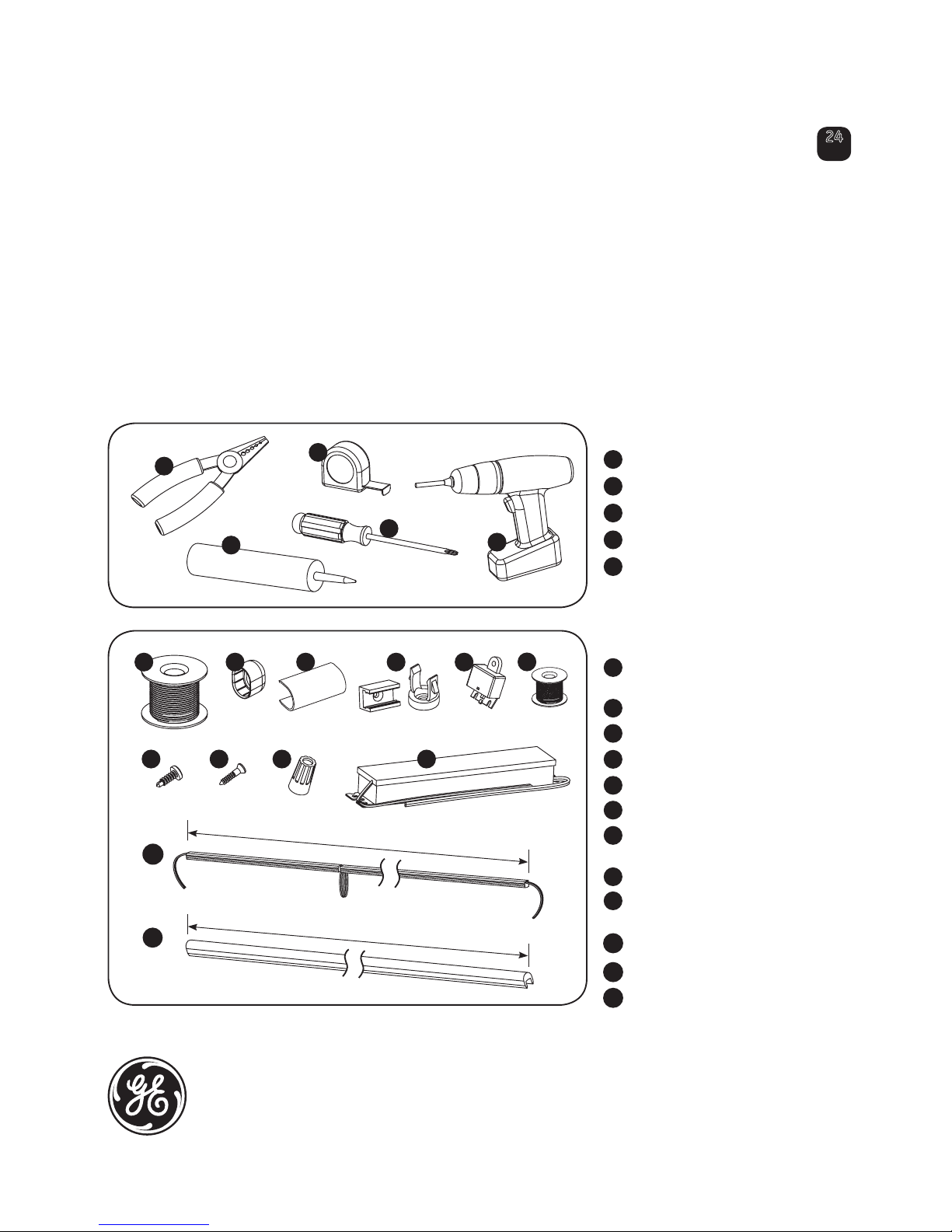
Tools required:
Components required:
UL approved 18 AWG (0.82mm 2 ) supply
wire
End caps
Light guide connectors
Mounting clips
Weather box
22 AWG (0.33mm
2
) tie-wire
#8 & #10 (M3 or M4) self drilling pan
head screws
#6 (M2) screws
UL approved 22-14 AWG (0.33-2.08mm
2
)
twist-on wire connectors
Tetra 24 Volt Power Supply
Tetra Contour light engine
Tetra Contour light guide
Tools and Components
1
2
3
4
5
6
7
8
* NOTE: xx = color code
9
10
11
12
(GERDXNLE1, GERCXNLE1, GEYAXNLE1, GEGLXNLE1, GEBLXNLE1, GEWHXNLE1, GEWWXNLE1)
Installation Guide
Tetra®Contour
LED Lighting System
GE
Lighting Solutions
24
Volt
imagination at work
) m
4
4
.
2
(
t
e
e
f
8
1 2 4
7
9
5
) m
4
4
.
2
(
t
e
e
f
8
3
10
11
12
8
1
2
4
3
5
Wire stripper/cutter
Tape measure
Screwdriver
Electrical grade silicone
Cordless drill
1
2
3
4
5
®
6
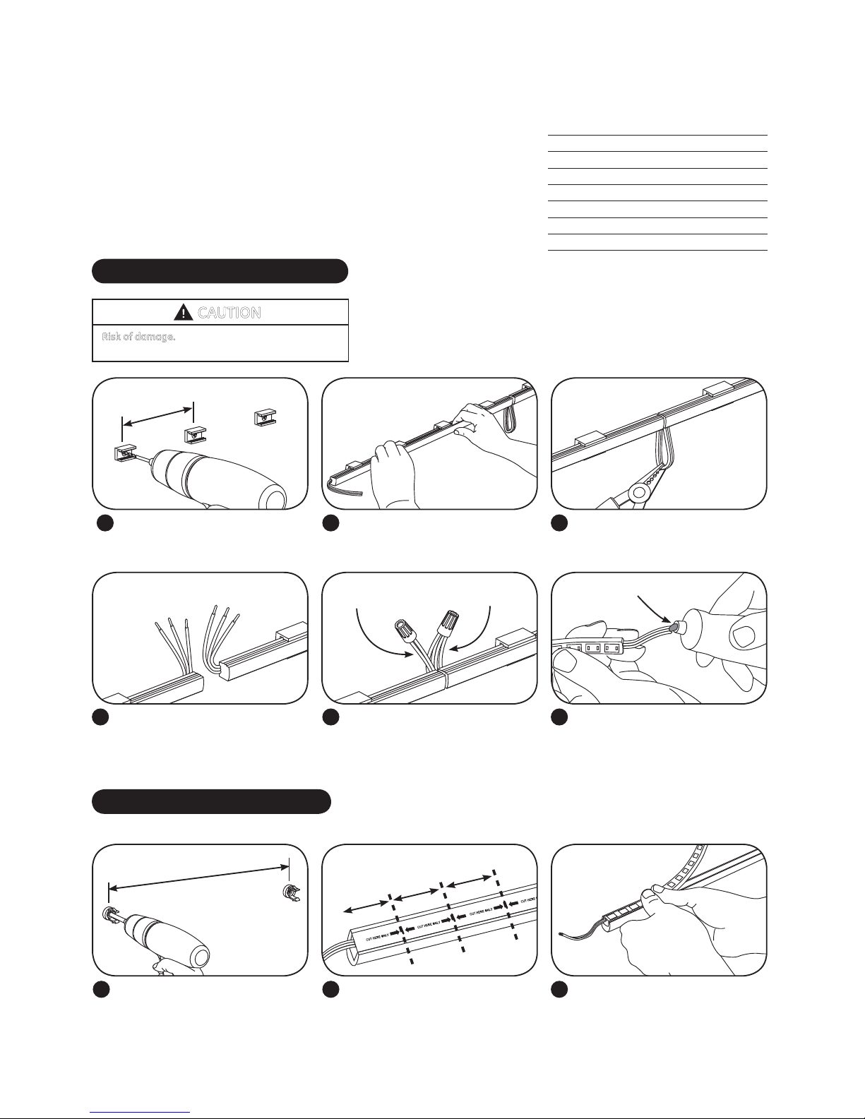
Attaching Light Engines
1
Push each 16 in. (406mm) light engine
segment into the clips. Fold loose
wires behind light engines.
2
Install a mounting clip, using #6 (M2)
counter sink screws, every 5–8 inches
(127–203mm) on center until the end
of the run is reached.
5-8 in. (127-203mm)
Electrical grade silicone
3 1
Push the light engine segments down
into the light guide.
Install a minimum of one clip per 18 in.
(457mm) using #10 (M4) screws.
NOTE: Standard neon hardware can
also be used.
Plan the layout by measuring the design layout and dividing by 8 ft. (2.44m) to
determine the required quantity of Tetra Contour. Refer to the Cutting Resolution Chart
at right when cutting any Tetra Contour section.
NOTE: Do not use more than one suffix code for each respective application, as mixing
suffix codes may result in appearance variation. Suffix code can be found on the
packaging label.
METHOD A - without light guides
If required, cut wire loops between
sections or through light engine in the
appropriate area (refer to the Cutting
Resolution table above).
3
Use twist-on wire connectors to join
cut wires together. Fold wires behind
light engines.
6 5
CAUTION: Anytime light engine or
supply wire is cut and wire is exposed,
electrical grade silicone must be
applied (see list on the next page for
recommendations).
METHOD B - with light guides
2
Push into clips
If required, cut wire loops between
sections or through light engine (refer
to the Cutting Resolution table above).
NOTE: Installation methods shown are for straight runs. For custom shapes, refer to the Light Guide Forming Instructions.
18 in. (457mm)
Connect two
negatives (–)
Connect four
positives (+)
NOTE: Installation methods shown are for straight runs. For custom shapes, install
mounting clips at regular intervals throughout the shape to provide adequate
support for the light engine.
NOTE: DO NOT bend the light engine to an inside radius that is tighter than 5/8 in.
(16mm). The light engine is not intended for excessive or repetitive bending.
Cutting Resolution Table
4
Separate wires and identify outer
conductors as positive (+) and
middle conductors as negative (–).
Strip ends back 0.5 in. (13mm).
+
+
+
+
–
–
Separate wires
CAUTION
Risk of damage. Light engine by itself is intended
for use in dry indoor application only.
Light Engine Color Cutting Resolution
Red 2.67 in. (68mm)
Red-Orange 2.67 in. (68mm)
Amber 2.67 in. (68mm)
Green 2.00 in. (51mm)
Blue 2.00 in. (51mm)
White 2.00 in. (51mm)
Warm White 2.00 in. (51mm)
 Loading...