

GE Lighting GELT403040CTR-SY, GELT403050CTR-SY, GELT403050CTR-SB, GELT403650CTR-SB, GELT403640CTR-SB Retrofit Installation Manual
...
imagination at work
GE
Retrofit Installation Guide
Lighting
™
IMMERSION
LED Refrigerated Display Lighting
Vertical Cases
RV40 Series
Center Mullion LED Lights
750 mm (30-inch): GELT403050CTR-SY/-SB (79777/79780), GELT403040CTR-SY/-SB (79783/79786)
900 mm (36-inch): GELT403650CTR-SY/-SB (79795/79798), GELT403640CTR-SY/-SB (79801/79804)
Description Code (Single Unit Product Number / 10-Pack Product Number)
BEFORE YOU BEGIN
Read these instructions completely and carefully.
FOR YOUR SAFETY
Read and observe all CAUTIONS and WARNINGS shown
throughout these instructions.
• Installation to be performed by factory trained service personnel only.
For use inside a commercial refrigeration case with packaged foods only.
•
This device complies with part 15 of the FCC Rules. Operation is subject to the
following two conditions: (1) This device may not cause harmful interference, and (2)
this device must accept any interference received, including interference that may
cause undesired operation.
NOTE: This equipment has been tested and found to comply with the limits for a Class A
digital device, pursuant to part 15 of the FCC Rules. These limits are designed to provide
reasonable protection against harmful interference when the equipment is operated in a
commercial environment. This equipment generates, uses, and can radiate radio frequency energy and, if not installed and used in accordance with the instruction manual, may
cause harmful interference to radio communications. Operation of this equipment in a
residential area is likely to cause harmful interference in which case the user will be
required to correct the interference at his own expense.
This Class [A] RFLD complies with the Canadian standard ICES-003. Ce DEFR de la classe
[A] est conforme à la NMB-003 du Canada.
WARNING / AVERTISSMENT
Risk of electrical shock. Disconnect power before servicing or installing product.
/ Risque de choc électrique. Couper le courant avant de réparer ou installer le produit.
LED DRIVER COMPATIBILITY
This system is compatible with the GEPS4000NCMUL-SY
LED Driver. Please refer to the separate LED driver installation
guide for appropriate wiring connections.
CAUTION / ATTENTION
Risk of injury. While performing installations described, gloves, safety
glasses or goggles should be worn. / Risque de blessure. Lors de l'exécution
des installations décrites, des gants, des lunettes de sécurité ou des lunettes
de protection doivent être portées.
A. Use this unit only in the manner intended by the manufacturer. If you
have any questions, contact the manufacturer.
B. Before servicing or cleaning unit, switch power off at the service panel
and follow appropriate lock out /tag out safety procedures.
PREPARE ELECTRICAL WIRING
Electrical Requirements
•
The power supply must be supplied with 100-240 VAC,
50/60 Hz., and connected to an individual properly
grounded
circuit breaker or time delay fuse.
Wiring must be 2 wire with ground and rated for
•
• Do not overload driver, follow installation instructions
for the GEPS4000NCMUL-SY.
• Ensure that all connection points are sealed for damp
location using the appropriate method per the NEC or
local electrical code.
branch circuit, protected by a 15 or 20 ampere
75°C (167°F).
1
WARNING/AVERTISSEMENT
5LVNRI¿UHRUHOHFWULFVKRFN/XPLQDLUHZLULQJDQGHOHFWULFDOSDUWVPD\EHGDPDJHGZKHQGULOOLQJIRULQVWDOODWLRQRI/('UHWUR¿WNLW &KHFNIRU
H
QFORVHGZLULQJDQGFRPSRQHQWV
5LVTXHGHIHXRXpOHFWURFXWLRQL
es pièces et câbles électriques risquent d’être endommagés lors du perçage
GHVWURXVSRXUO·LQVWDOODWLRQGXOXPLQDLUHj'(/9HXLOOH]YpUL¿HUVLGHVFkEOHVHWFRPSRVDQWHVVHWURXYHQWGHUULqUHODSDURLDYDQWGHSHUFHU
7RSUHYHQWZLULQJGDPDJHRUDEUDVLRQGRQRWH[SRVHZLULQJWRHGJHVRIVKHHWPHWDORURWKHUVKDUSREMHFWV3RXUpYLWHUOHQGRPPDJHPHQWGH
F
kEODJHRXODEUDVLRQQHSDVH[SRVHUOHFkEODJHDX[ERUGVGHIHXLOOHVGHPpWDORXGDXWUHVREMHWVWUDQFKDQWV
Remove Existing Lighting Components
Tools Required
4
5
1
Wire stripper/cutter
2
Tape measure
3
Screwdriver
4
Cordless drill
5
Hammer
6
2.8mm (7/64-inch) drill bit
7
Center punch
6
• For retrofit only. If you are an OEM, please refer to the OEM
7
Components Required
2
4
1
LED light
2
LED driver
3
Wire cover
4
M3.5x1.3x13 (#6-32 x 1/2 inch) screws
5
Twist lock splice wire connectors
Fluorescent Component Location
Installation Guide.
• Refer to manufacturing manual for refrigeration case to
identify lighting control circuits. Ensure that power is switched
off at the service panel for the lighting circuit. If a lighting
power switch is not provided in the refrigeration case, power
removal can be performed at the main breaker panel.
• Locate existing lighting components including ballasts,
lampholders, lamps, and lampguards in the refrigeration
case for removal. Please refer to refrigeration manual for any
questions dealing with component locations.
• Remove lamps, lampholder and lamp guards. Cut the wiring,
making the cut as close to the lampholder as possible. Do not
remove wiring from case as it will be utilized to attach the LED
light. Dispose of components per federal and local regulations.
• Locate ballast within system. The most common location is in
the mullion or the electrical raceway found in the bottom of
the refrigerated case.
• Disconnect ballast input and output connectors. Cut the
ballast connector wires nearest to the connector and remove
connector. Unscrew the mounting screws that attach ballast
and remove ballast. Dispose of ballasts according to federal
and local regulations. LED driver installation will begin at Step
7 and Step 8.
• To install the LED light, first identify the wiring for connection
to the LED driver. After removing the connector from ballast,
leave the existing ballast input and output wires for
reconnection in a later step.
2
Lamp with lamp guards
A
(behind mullion)
Lamp holders
B
Ballast
C
1. Mullion
2. Raceway
3. Overhead door frame
1
3
5

2
of mullion
Total width
10 mm (3/8")
For 750 mm (30-inch)
LED Lights:
687 mm (27 1/32")
Center
punch
at intersection
and drill a
2.8 mm (7/64")
hole
mullion
Half total
width of
LED Driver wires top
For 900 mm (36-inch)
LED Lights:
836 mm (32 29/32")
Prepare for Installation of
Center LED Lights
• Measure the total width of the mullion, and mark a vertical
line half the total width near the top and bottom of the mullion.
•
Prepare for the upper end of the Center LED Light . Mark a
horizontal line a minimum 54 mm (2 1/8-inches) from the top
of the mullion, and another horizontal line 10 mm (3/8-inches)
below this line.
• Prepare for the lower end of the Center LED Light . For
750 mm (30-inch) LED Lights, mark a horizontal line 687 mm
(27 1/32-inches) beneath the first line drawn for the top
Mounting Tab. For
horizontal line 836 mm (32 29/32-inches)
line drawn for the top Mounting Tab.
• Point the center punch directly at the intersection of the
horizontal lines and the vertical line (top and bottom)
establish a dimple.
• Use power drill and 2.8 mm (7/64-inches) drill bit to drill
holes at the
horizontal lines.
900 mm (36-inch) LED Lights, mark a
beneath the first
and
intersection of the vertical center line and the
3
WARNING / AVERTISSMENT
Risk of electrical shock. Only those open holes indicated in the photographs and/or drawings may be made or altered as a result of kit installation. Do not leave
any other open holes in an enclosure of wiring or electric components / Risque de choc électrique. Seuls les trous ouverts indiqués dans les photos et / ou les
dessins peuvent être faites ou modifiés à la suite du montage du kit. Ne pas laisser autres trous ouverts dans l'enceinte du câblage électrique ou composants.
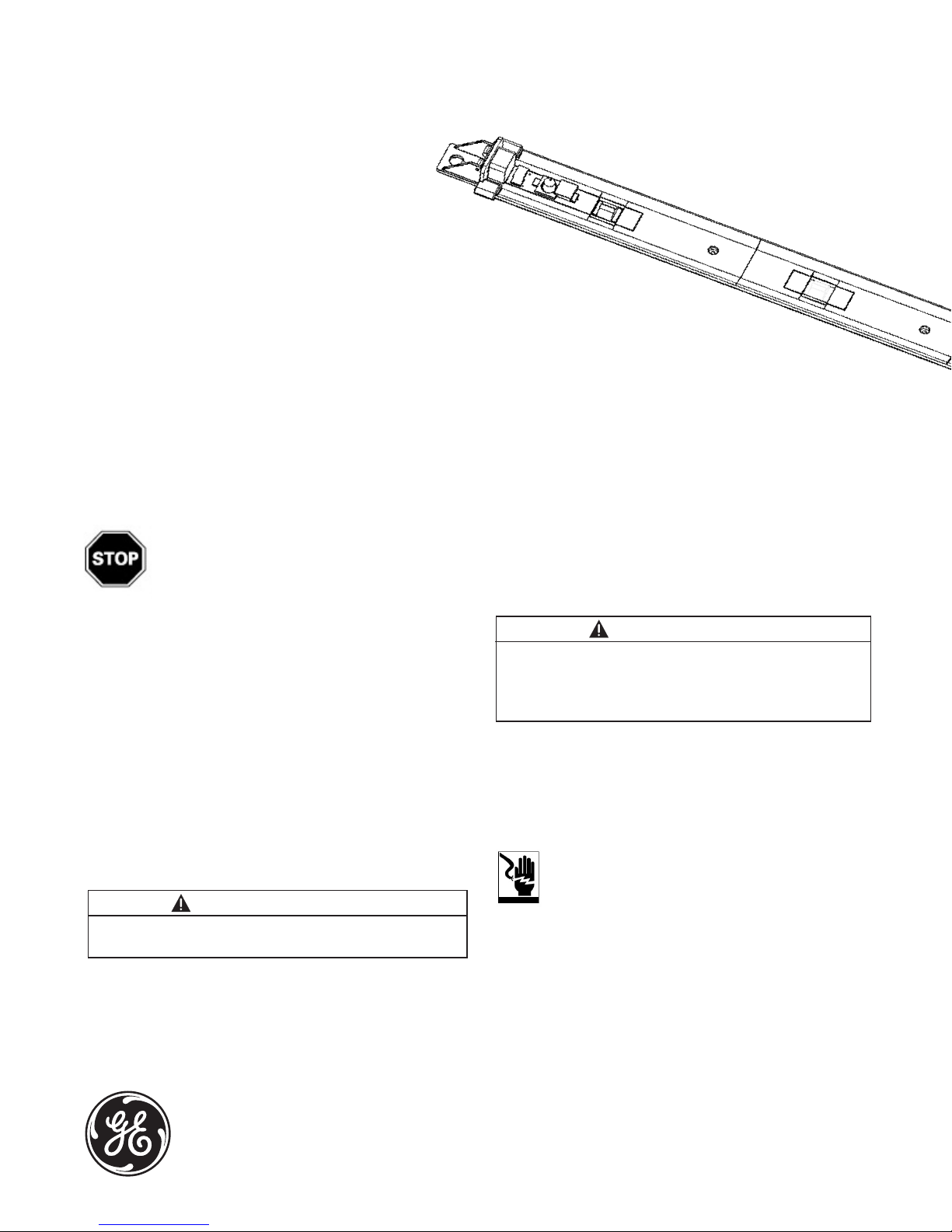
Install Center LED Lights
LED Driver
• Place the Center LED Light against the face of the
mullion
near the two holes drilled at the top.
• Insert a M3.5 x 1.3 x 13 (#6-32 x ½-inch) sheet metal screw
into the top slot of the Mounting Tab on the Center LED Light
and into the first hole that was drilled in the center mullion.
• Use a screwdriver to start threading the screw into the
drilled hole.
• Refer to the manufacturing manual for door frame to ensure
there are no components contained inside the mullion that
could be drilled through. Use a M3.5 x 1.3 x 13 (#6 - 3/4-inch)
self-drilling screw to attach the Center LED Light into one
or two of the additional drill through holes located near the
center of the LED Light.
• Repeat for the second screw, and for the lower end of the
Center LED Light.
• Refer to wiring diagram on page 5. Connect the red and black
output wires from the LED Light to the red and black wires on the
LED Driver using the twist lock splice wire connectors provided.
Mounting Tab
Center LED Light
Power Leads
Leads
3
 Loading...