

GE Lighting 90003 User Manual
GE Installation Guide
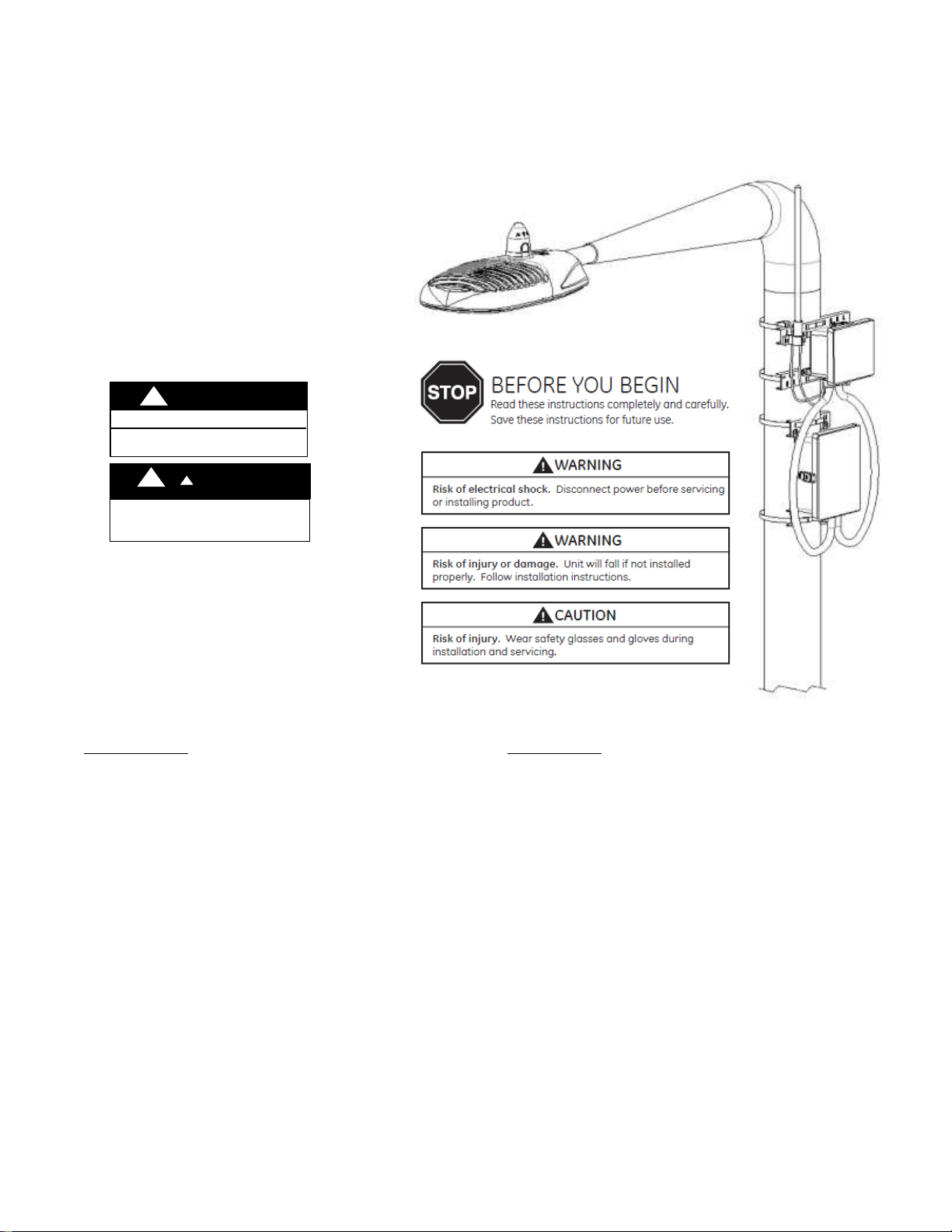
RISK O F ELECTR IC SHOCK
WARNING
INSTAL L IN ACCORDA NCE WITH
NATIO NAL ELECTR IC CODE
WANING
WARNING
!
!
!
!
RISK OF INJURY. The gateway or cellular should be
mounted securely upon pole so that it will not move
or rotate freely.
Lighting
LightGrid
Wireless Outdoor Lighting Control
FCC statements:
IC Statements:
This device complies with part 15 of the FCC Rules.
Operation is subject to the following two conditions:
This device may not cause harmful interference, and
this device must accept any interference received,
including interference that may cause undesired
operation.
Caution:
Changes or modifications not expressly approved by the
party responsible for compliance could void the user's
authority to operate this equipment.
This device complies with Industry Canada licenceexempt RSS standards.
Operation is subject to the following two conditions:
This device may not cause harmful interference, and
this device must accept any interference received,
including interference that may cause undesired
operation.
Cet appareil est conforme aux normes RSS exemptees de
licence de Industrie Canada. Son fonctionnement est
soumis aux deux conditions suivantes:
Cet appareil ne doit pas provoquer d'interférences et
cet appareil doit accepter toute interférence, y
compris celles pouvant causer un mauvais
fonctionnement de l'appareil.

Contents
Components ................................................................................................................................................. 3
Specifications ................................................................................................................................................ 4
Electrical Connections .................................................................................................................................. 5
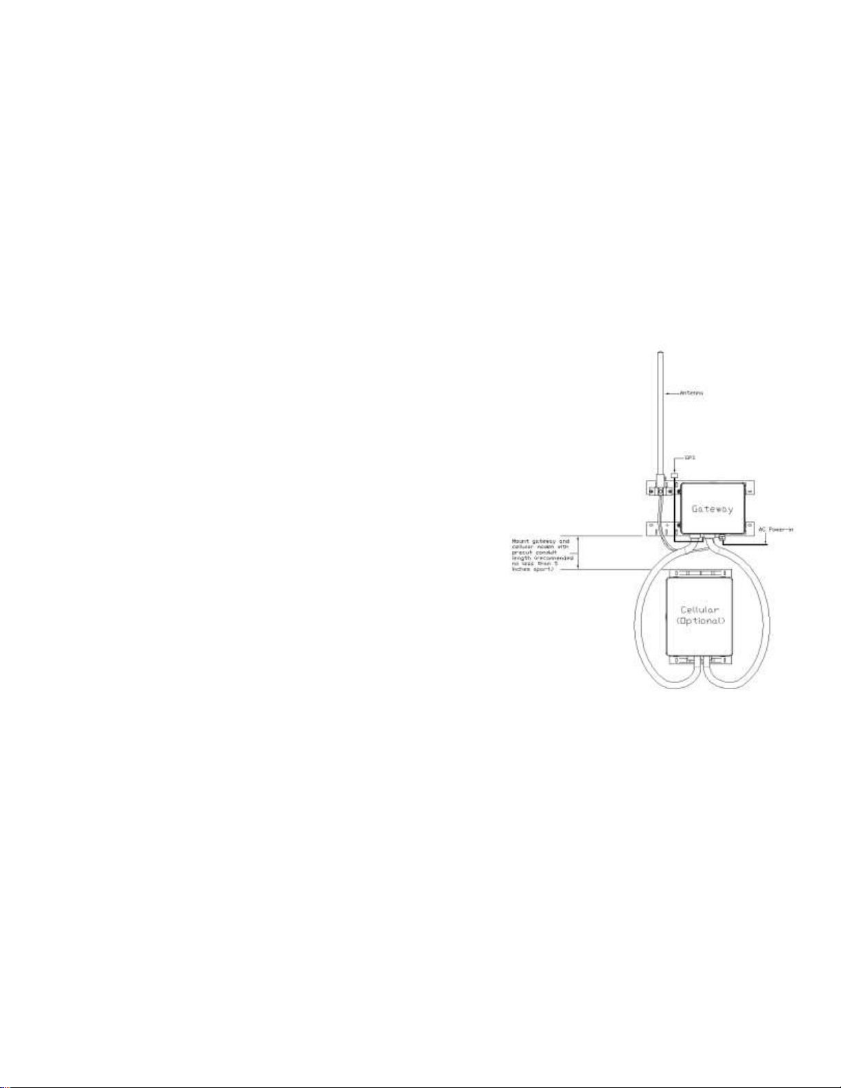
Mounting Gateway and Cellular ................................................................................................................... 6
Powering Gateway & System Check ............................................................................................................. 7
Troubleshooting Cellular Modem ............................................................................................................... 10
Controller Installation ................................................................................................................................. 11
Components
The Gateway and Cellular Units have been packed so that no parts should have been damaged during transit,
inspect to confirm.
Gateway Package Includes:
ELWG0CXXGC – 120/277vac or ELWGHCXXGC – 347-480vac Gateway Unit (1pc)
Conduit fitting (2pcs) – mounted to enclosure;
Grey Gland (3pcs),
Antenna cable (1pc), - mounted to gland;
Antenna Pole (1pc), - to be installed;
Pole mounting bracket (2pcs), -mounted to enclosures;
Cellular Package (optional) Includes:
ELWM0CXV – Cellular Unit – 120/277v (1pc)
Conduit fittings 30” (2pcs), - mounted to enclosure;
Ethernet cable 42” (1pcs), mounted to fitting;
Power Cable 36” (1pc), mounted to fitting;
Pole mounting bracket (2pcs), mounted to enclosure;
Additional parts/tools (customer supplied)
Customer may require parts listed below:
o Conduit: Nonmetallic Type B liquid-tight ¾” Dia.
(e.g. Cooper LTCOND75NM100);
o Power Cable: 12AWG~18AWG per cord;
o Ethernet Cable: Cat5e outdoor Ethernet cable;
o Tools:
- Philips Head Screw driver;
- Steel Strap Cutter;
Optional:
o Caps over gland/conduit fittings;
o RIPLEY Ancillary Power Tap #5731
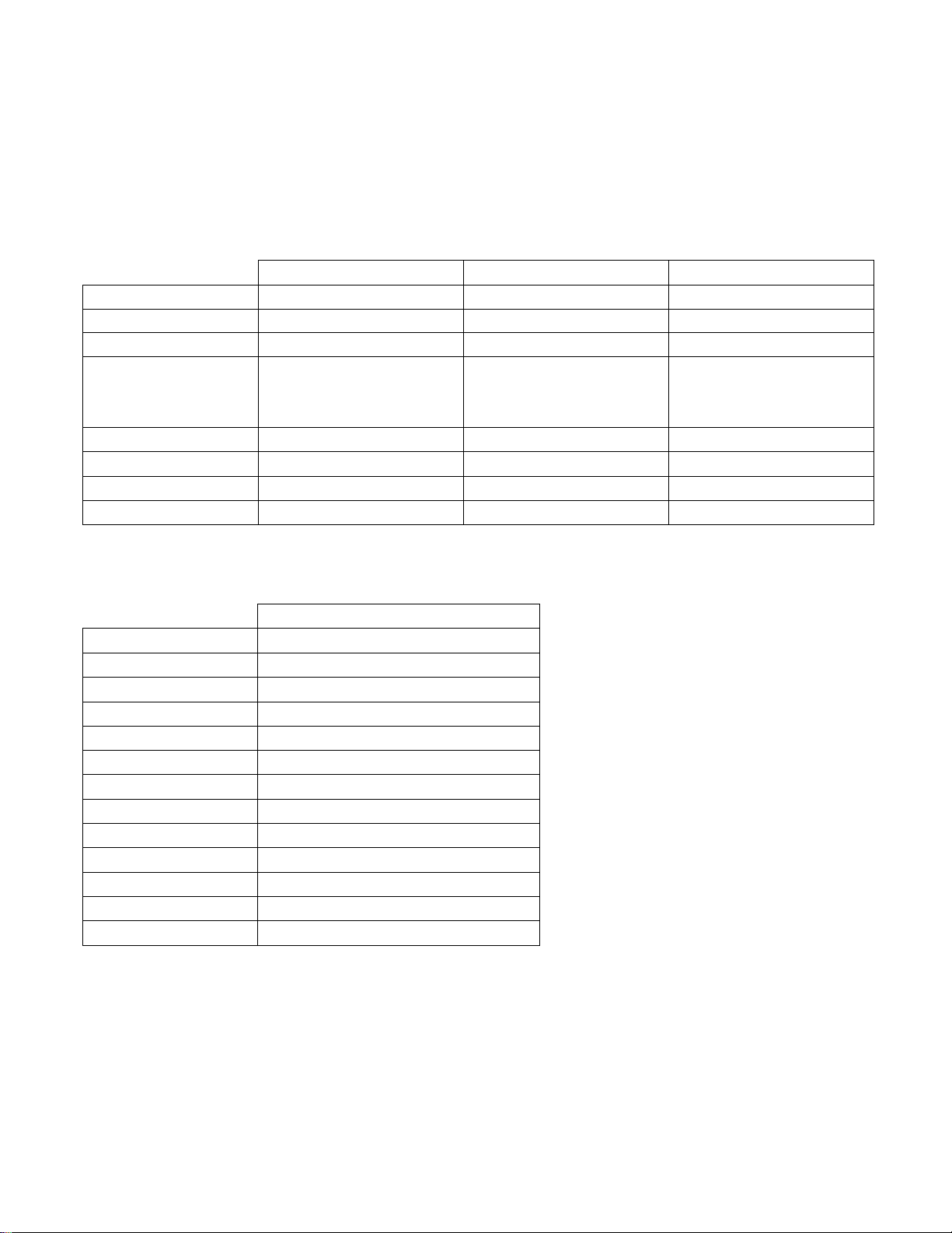
Specifications
Gateway
Gateway
Cellular
Part Number
ELWG0CXXGC
ELWGHCXXGC
ELWM0CXV
Input Voltage
120-277vac
347-480VAC
120-277VAC
Weight
7 lbs (3.18kg)
7 lbs (3.18kg)
8 lbs (3.63kg)
Dimensions (L x W x H)
7.6"x16"x11"
(193x406x280mm)
7.6"x16"x11"
(193x406x280mm)
15"x13"x7"
(381x330x178mm)
FCC ID
PUU90002
PUU90002
-
FCC Compliance
Part 15 Subpart C (Class B)
Part 15 Subpart C (Class B)
Part 15 Subpart C (Class B)
Mounting Height
24 ft. - 40 ft (8.2 m-12.2 m)
24 ft. - 40 ft (8.2 m-12.2 m)
24 ft. - 40 ft (8.2 m-12.2 m)
Temperature
-40°- 120°F (-40 - 50C)
-40°- 120°F (-40 - 50C)
-40°- 120°F (-40 - 50C)
Controller
Part Number
ELWN0A_._._1B_._AD
Input Voltage
120-277VAC
Weight
1 lb (0.45kg)
Dimensions (L x W x H)
1.5"x0.6"x0.6" (38.1x15.24x15.24mm)
FCC ID
PUU90003
FCC Compliance
FCC 47 CFR Part 15 C.247 (Class B)
IC ID
10798A-PUU90003
IC Compliance
RSS-247, Section 5
Mounting Height
Temperature
-40° to 120°F (-40 to 50C)
Controller Standard
ANSI 7 Pin
Controller Meter
0.5% Utility Grade
 Loading...