

Water Sensor Kit
quick setup guide
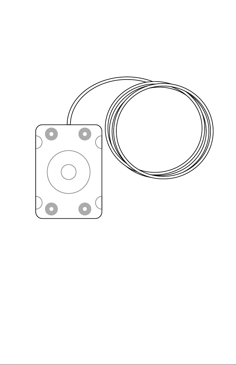
Your Water Sensor Kit should include the following items:
“WaterBug” Water Detection Sensor
(attached cable will either be 15ft (4.5m) or 100ft
(30.5m), depending on which option was chosen at time
of order.)
1Water Sensor Kit quick-start guide (rev.140729A-IT) Geist, Lincoln, Nebraska, USA — geistglobal.com
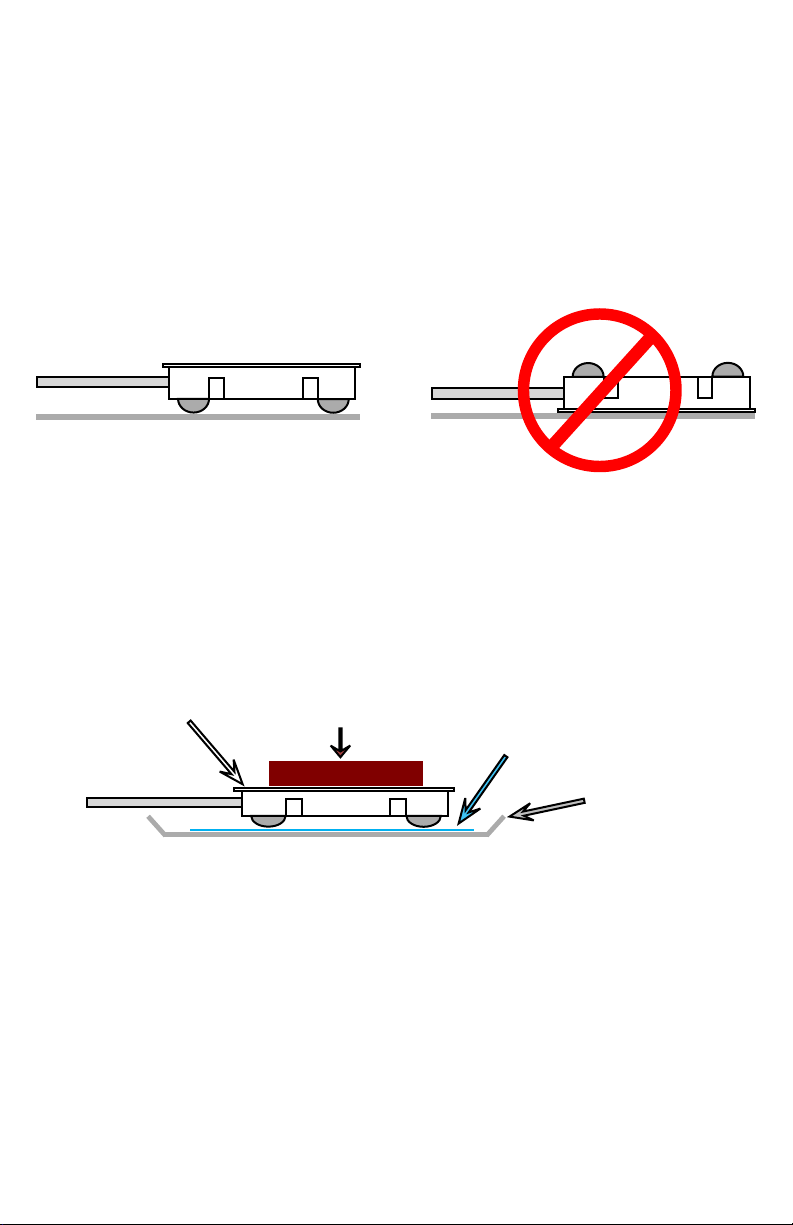
MOUNTING THE WATER SENSOR:
The sensor must be placed with the metal contact points facing downwards, in contact
with the floor, as shown here. It is via these contact points that the sensor detects dampness
underneath it; if it is placed with the contacts facing upwards, it won’t detect water until
the water rises high enough to cover the entire sensor.
If necessary, a small weight may be placed on top of the sensor to keep it from moving
if the cable is disturbed. The weight should not be greater than approx. 1lb (450g), as
heavier weights may damage the sensor; if that isn’t sufficient to keep the sensor in place,
securing the cable with clips or mounting brackets is recommended.
The sensor can also be installed inside places where water is likely to collect, such the
overflow drip pan of an air-conditioning system. If the sensor is to be used for such
applications, though, it must not be placed in direct contact with a metal surface! Doing
so will short the contact points together through the metal, causing the device to
continuously read full conductivity (“wet”). To prevent this from occurring, place a thin
sheet of insulating material – such as a piece of plastic cut from a sheet protector, a piece
of posterboard or other thick paper, or a thin (approx. 0.5mm or 1/32”) sheet of balsa wood
– in between the sensor and the surface, as shown below, to keep the contact points on the
sensor from touching the metal surface underneath.
water sensor
weight
insulator
(plastic, paper, etc.)
air conditioner
drip pan (metal)
Note that the sensor depends on electrical conductivity to determine the presence of
water underneath it. Therefore, distilled or deionized water may provoke little, if any
response from the sensor, since such highly purified water is often only weakly conductive.
Similarly, the sensor may not be suitable for detecting leaks of liquids other than water, if
such liquids are not electrically conductive.
The sensor should not be left immersed in water for extended periods. Under no
circumstances should the sensor be exposed to or immersed in any corrosive acid or
alkaline substances; it is not designed for such applications.
If the sensor gets wet, then continues to show a “wet” (high conductivity) condition
even after it’s dry again, impurities in the water may have deposited themselves on the
sensor. Try cleaning the sensor with rubbing alcohol, then let it dry completely before
reinstalling it.
2Water Sensor Kit quick-start guide (rev.140729A-IT) Geist, Lincoln, Nebraska, USA — geistglobal.com

CONNECTING THE WATER SENSOR TO A GEIST
ENVIRONMENTAL MONITORING UNIT:
The Water Sensor is directly compatible with any model of RSE, GRSO, or GBB-series
monitoring unit which has analog-sensor inputs. Models which do not have built-in analog
inputs, such as the RSMINI or GBB15, will require the use of an appropriatelyprogrammed Analog-to-Digital converter (sold separately) to use the water sensor. (An
A-to-D converter can also be used if all of your unit’s analog inputs are already occupied
with other sensors. Information on how to set up and use the water sensor with the
analog-to-digital converters can be found in the user guide for that device.)
The red and black wires from the sensor are connected to the analog-input terminals as
shown here. (Different models have different terminal-block styles.) Note that since the
sensor is a simple conductivity (resistance-detecting) sensor, with no inherent signal
voltage or polarity of its own, the actual order of the wires is not important; however, for
consistency, black should be connected to the “C” terminal and red should go to the
corresponding numbered terminal.
RSE-style terminals
C C
1 2 3
GRSO-style terminals
1
C
C3C4C
2
C
5
GBB-style terminals
ANALOG INPUTS
Dry Contact / 0-5VDC
6
C
C 1
C 2 C 3 C 4
3Water Sensor Kit quick-start guide (rev.140729A-IT) Geist, Lincoln, Nebraska, USA — geistglobal.com

SENSOR CONFIGURATION AND ALARM-THRESHOLD SETTINGS:
Unlike digital sensors such as the GTHD Temperature/Humidity sensor, analog sensors do not
automatically show up in the monitoring unit’s web page when connected. Since there is no
exchange of digital data between the unit and sensor, the unit has no way to know whether a sensor
has been connected to the analog input or not. Therefore, sensors connected to the analog inputs need
to be configured manually. (The following screenshots are taken from a GBB100, but the process
for configuring other models is essentially the same.)
First, click the Display tab, then locate the
Analog Sensors setting block at the bottom,
similar to the one shown here. Change the
Friendly Name of the analog input which
corresponds to the one you connected the water
sensor’s wires to as above, set Min to 100 and
Max to 0, then click Save Changes. (Unit can be
left at its default value.) This will “reverse” the usual scaling of the analog inputs, so that a dry sensor
will read 0 and the reading will increase towards 100 as the surface under the sensor gets wet. (If
Min and Max were left at their defaults, the sensor would start with a high number when dry and
decrease towards 0 as the sensor got wet, which is the opposite of what most users would expect to
see.)
Next, click the Alarms tab. Analog sensors are
considered part of the unit’s own sensor package,
so they will be listed along with the rest of the
unit’s internal sensors, not as separate devices of
their own. Click the Add New Alarm button for
the monitoring unit’s internal sensors, then
choose the analog input whose name corresponds
to the one you set in the prior step (“Water Sensor”, in this example) from the drop-down box.
Normally, the sensor should show a value close to 0 with the above settings. However, depending
on the surface the sensor is sitting on, the “dry” value may be a little above 0 if the surface itself is
slightly conductive. Setting a trip theshold of Trips if: Above and Limit: 20 is a good place to start;
if you notice the sensor false-triggering too often, increase the limit until the false triggers stop.
(Cleaning the sensor and underlying surface may also help stop false triggering.) Select any other
actions (delay, repeat, e-mail recipients, etc.) as desired, then click Save Changes.
Test the configuration by clicking on the Sensors
or Overview page, then put the sensor on a wet
surface. The reading should turn red, indicating
a tripped alarm, displaying a value well above
the “20” threshold, as shown here. (If this
doesn’t happen within a few moments, hit [F5] to
refresh the web page.)
Dry the sensor, wait a few moments, then refresh
the web page. The reading should turn black
(“no alarm”), with a reading close to 0 again.
4Water Sensor Kit quick-start guide (rev.140729A-IT) Geist, Lincoln, Nebraska, USA — geistglobal.com
 Loading...