

Page 1

Instruction Manual
Rack Power Distribution Unit
BR, SP, SVR, VRT,
NSV and VSS Series
Geist Manufacturing 1821 Yolande Ave., Lincoln, NE 68521
800.432.3219 | 402.474.3400 | F: 402.474.4369 | www.geistmfg.com
Page 2

Contents
Contents............................................................................................................................2
Specifications....................................................................................................................3
Overview 3
Environmental 3
Electrical 3
Receptacle Ratings 3
EMC Verification 4
Installation .......................................................................................................................5
Instructions 5
Guidelines 5
Mounting...........................................................................................................................6
Optional Surge Suppression............................................................................................14
Surge Protection Circuit Ratings 14
Optional Local Monitoring ...............................................................................................15
Power Meter 15
Current Meter 15
Service/Tech Support .....................................................................................................16
Service and Maintenance 16
More Technical Support 16
Table of Figures ..............................................................................................................17
Revision History..............................................................................................................18
Revision History..............................................................................................................18
GM1001.doc 2 Revision Date: 7/1/2009
Page 3

Specifications
Overview
The BR, SP, SVR, VRT, NSV, and VSS Series products are Power Distribution Units (PDU)
intended for connection to a 15 or 20 Amp AC Mains circuit. The PDUs may include optional
single pole thermal breakers for supplementary over-current protection of the output
receptacles. The VRT, SVR, NSV, and VSS Series are available in vertical configurations rated
125 V, while the BR and SP Series are available in horizontal configurations rated 125 V. All
PDU Series covered by this instruction sheet can optionally be configured with a Geist Power
Meter that provides local monitoring and display of Current, Voltage, Wattage, and Power
Factor.
Environmental
Temperature
Humidity
Elevation
Operating: 10°C (50°F) min 45°C (113°F) max
Storage: -25°C (-13°F) min 65°C (149°F) max
Operating: 5% min 95% max (non-condensing)
Storage: 5% min 95% max (non-condensing)
Operating: 0 m (0 ft) min 2000 m (6561 ft) max
Storage: 0 m (0 ft) min 15240 m (50000 ft) max
Electrical
See nameplate for unit ratings.
Receptacle Ratings
NEMA 5-15R or L5-15R 125 Volts, 15 Amp
NEMA 5-20R or L5-20R 125 Volts, 20 Amp
GM1001.doc 3 Revision Date: 7/1/2009
Page 4

EMC Verification
This Class A device complies with part 15 of the FCC Rules. Operation is subject to the
following two conditions: (1) This device may not cause harmful interference, and (2) this
device must accept any interference received, including interference that may cause undesired
operation.
This Class A digital apparatus complies with Canadian ICES-003.
Cet appareil numérique de la classe A est conforme à la norme NMB-003 du Canada.
Warning: Changes or modifications to this unit not expressly approved by the party responsible
for compliance could void the user’s authority to operate this equipment.
GM1001.doc 4 Revision Date: 7/1/2009
Page 5

Installation
Instructions
1. Using appropriate hardware, mount PDU to rack (see Mounting section for additional
instructions.
2. Plug PDU into de-energized 15 or 20 Amp branch circuit receptacle
3. Connect devices into PDU’s output receptacles. It is recommended that the devices are
turned off until all devices are connected to PDU
4. Turn on branch circuit to energize PDU.
5. Power on devices. Sequential power up is recommended to avoid high inrush current.
1
.
Guidelines
• If the PDU is installed in a cabinet the ambient temperature of the rack should be no greater
than 45°C.
• Install the PDU such that the amount of airflow required for safe operation of equipment is
not compromised.
• Mount the PDU so that a hazardous condition is not achieved due to uneven mechanical
loading.
• Follow nameplate ratings when connecting equipment to the branch circuit. Take into
consideration the effect that overloading of the circuits might have on over-current
protection and supply wiring.
• The PDU relies on the building installation for protection from over-current conditions. A
Listed circuit breaker is required within the building installation. The circuit breaker should
be sized according to the PDU’s nameplate ratings and local/national electrical codes.
• Reliable earthing of rack-mount equipment should be maintained. Particular attention
should be given to supply connections other than direct connections to the branch circuit.
The PDU must be connected to an earthed socket-outlet.
• The PDU is intended for Restricted Access Locations only and only qualified service
personnel should install and access the PDU.
• For pluggable equipment, install the PDU so that the input plug or appliance coupler may be
disconnected for service.
• Sequential power-up of devices powered by the PDU is recommended to avoid high inrush
current.
• Caution: Disconnect all power cords before servicing.
1
Branch Circuit should be sized based on the PDU’s nameplate electrical rating. A 12 Amp rated
PDU is intended for use on a 15 Amp Branch Circuit, while a 16 Amp rated PDU is intended for use
on a 20 Amp Branch Circuit.
GM1001.doc 5 Revision Date: 7/1/2009
Page 6

Mounting
Full Length Bracket
Using the full length bracket, mount PDU to rack as shown
Mini "L" Brackets (SLB-4)
Using the mini “L” brackets, attach PDU to rack as shown
GM1001.doc 6 Revision Date: 7/1/2009
Page 7
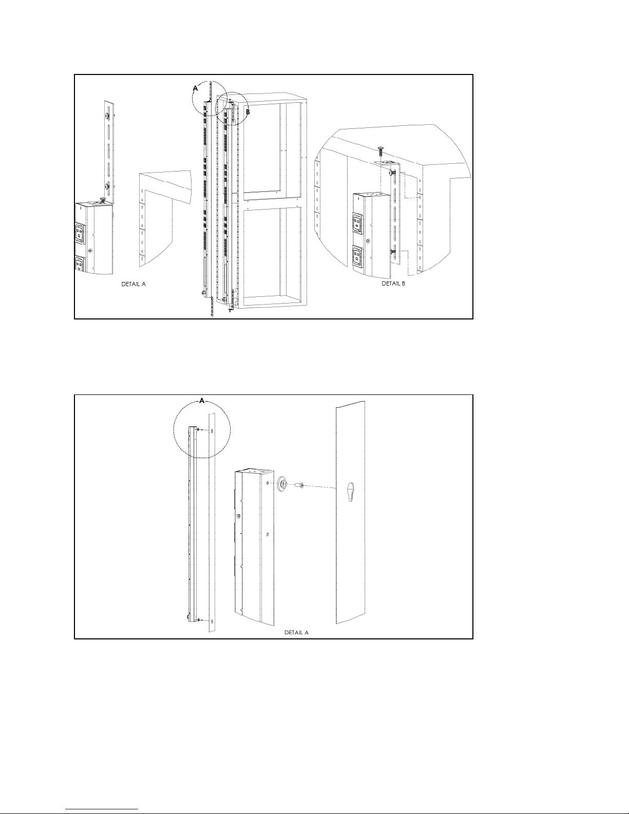
Vertical Extension Brackets (VCB-1)
Using the vertical extension brackets, attach PDU to rack as shown
Toolless Mounting Hardware (11621)
Secure toolless mounting buttons to PDU as shown. Use toolless buttons with key-holed slots built
into cabinet or with optional Geist key-holed brackets.
GM1001.doc 7 Revision Date: 3/25/2009
Page 8
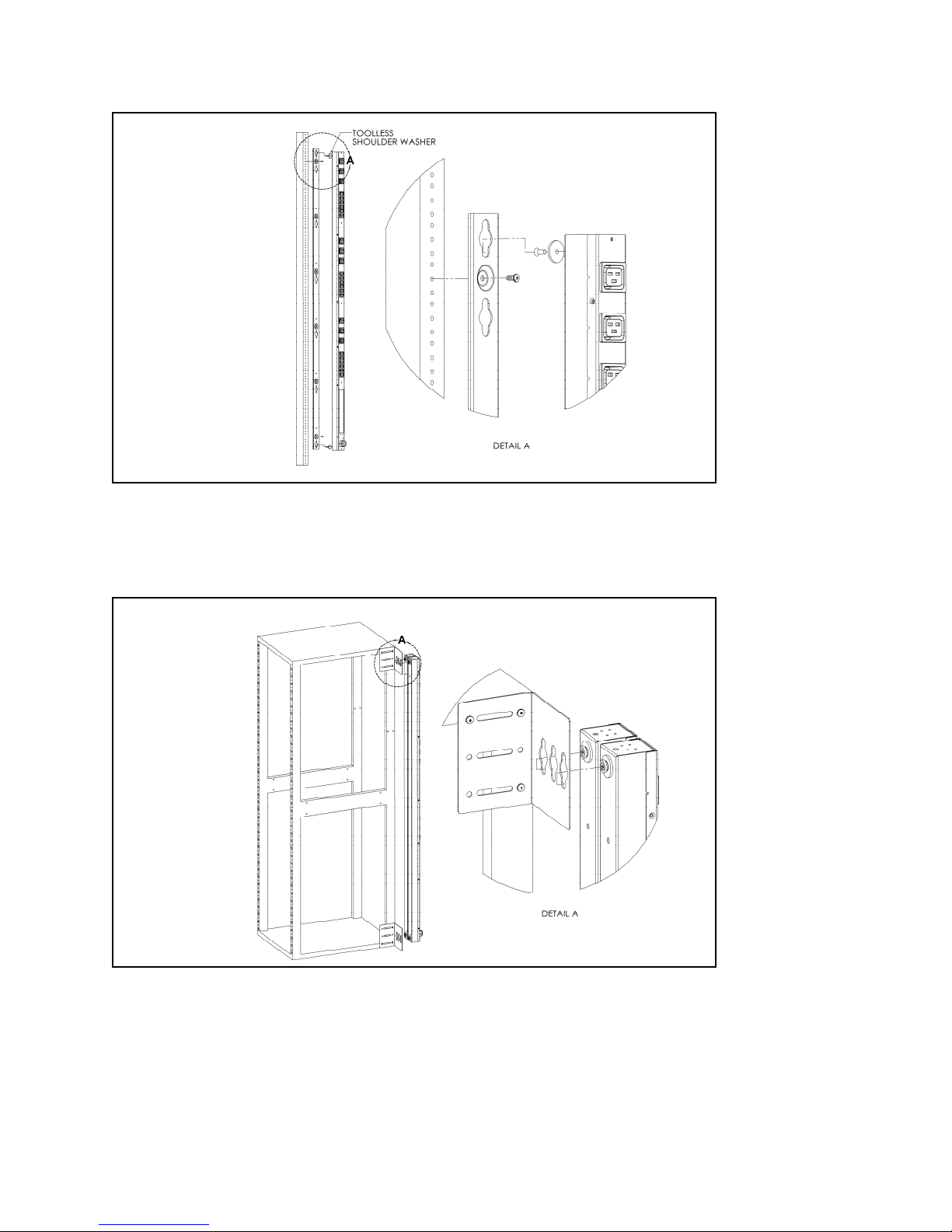
Toolless Full Length Bracket (TLFL)
Using full length toolless bracket and toolless mou nting buttons, attach PDU to rack as shown
Single Side Mount 2 Unit Brackets (TSMX2)
Using single side mount 2 unit brackets and toolless mounting buttons, attach PDU to rack as
shown
GM1001.doc 8 Revision Date: 3/25/2009
Page 9
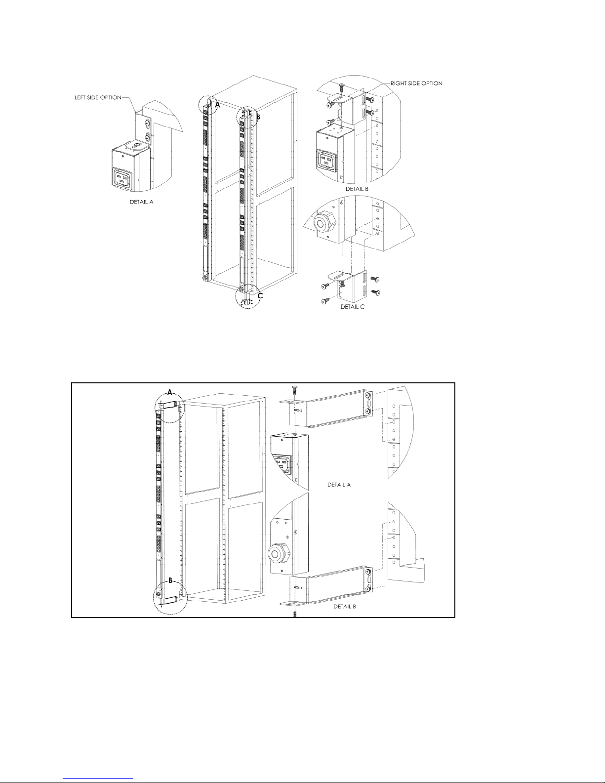
Offset/Side Mount Brackets (EZB-1)
Using the offset/side mount brackets, attach PDU to rack as shown.
7" Extension Brackets (XB-7)
Using the 7” extension brackets, attach PDU to rack as shown
GM1001.doc 9 Revision Date: 3/25/2009
Page 10
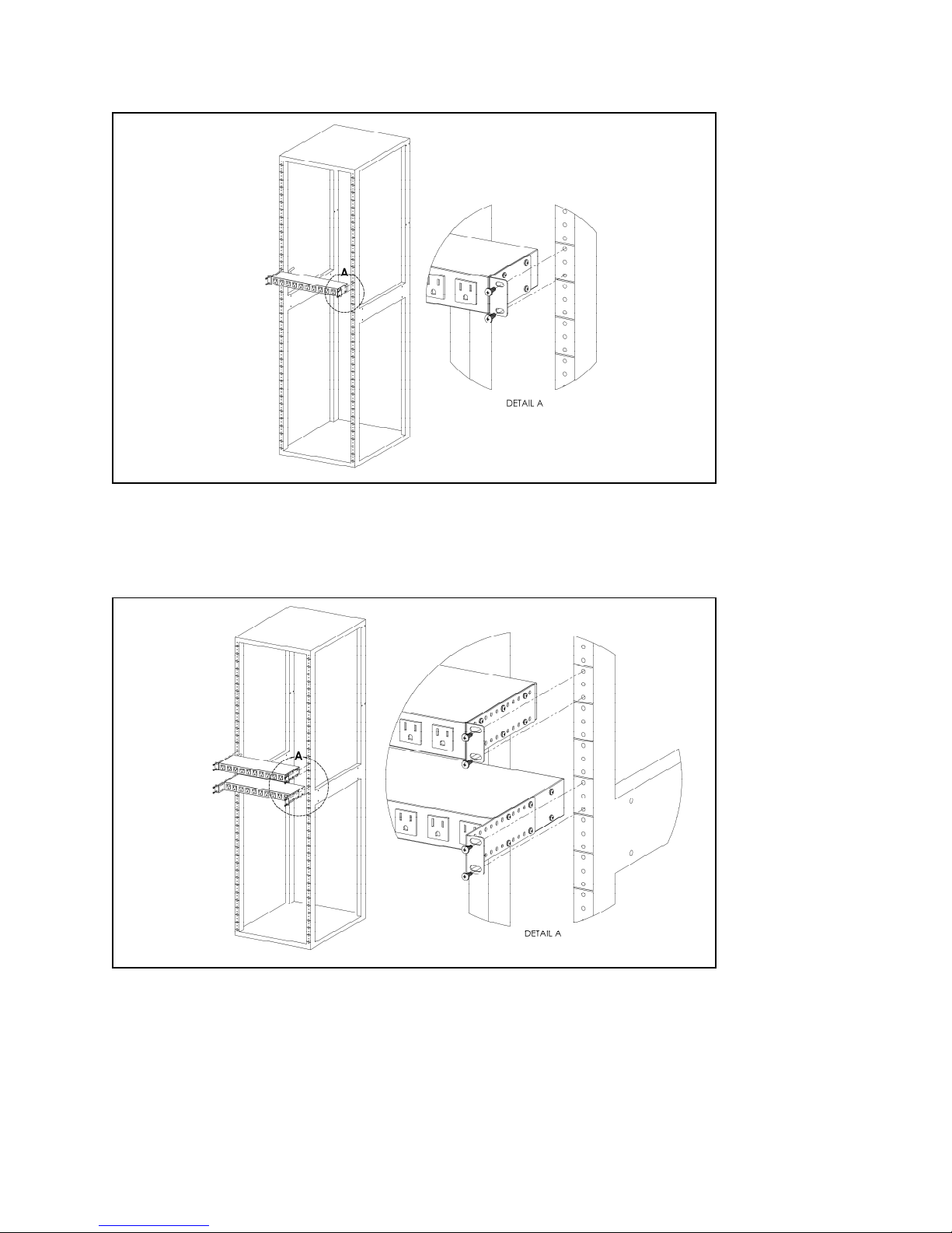
Flush Mount Brackets (FM)
Using flush mount brackets, attach PDU to rack as shown
Adjustable Mount Brackets (AM)
Using adjustable mount brackets, attach PDU to rack as shown
GM1001.doc 10 Revision Date: 3/25/2009
Page 11
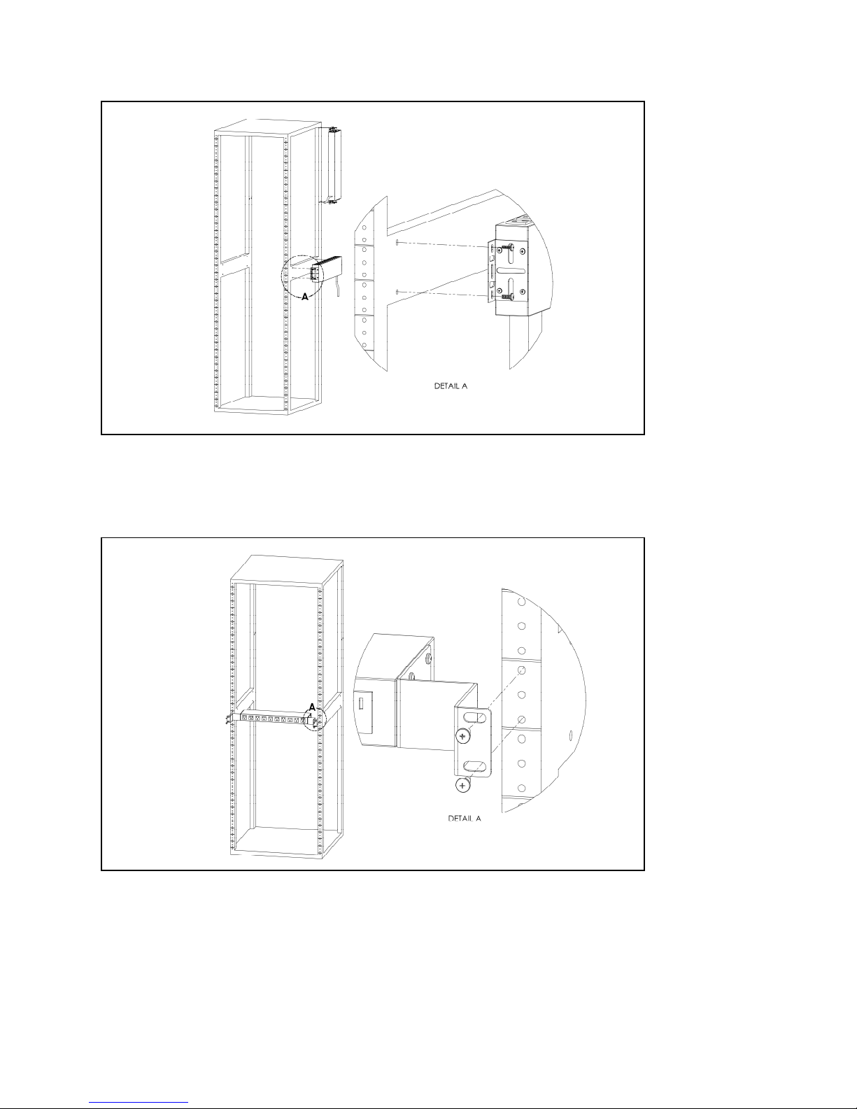
Panel Mount Brackets (PM)
Using panel mount brackets, attach PDU to rack as shown
23" Conversion Mounting Brackets (23-RM)
Using conversion mounting brackets, attach 19” PDU to 23” rack as shown
GM1001.doc 11 Revision Date: 3/25/2009
Page 12
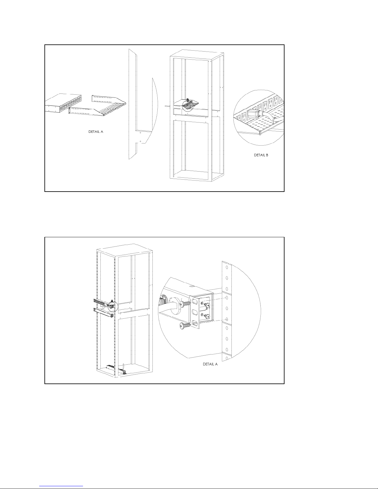
Cable Mount Bracket (CMB-1)
Attach cable mount bracket to PDU as shown; use tie-wraps to secure cords to bracket
19" Horizontal/Panel Mount Brackets (7938)
Using the 19” horizontal/panel mount brackets, attach PDU to rack as shown
GM1001.doc 12 Revision Date: 3/25/2009
Page 13
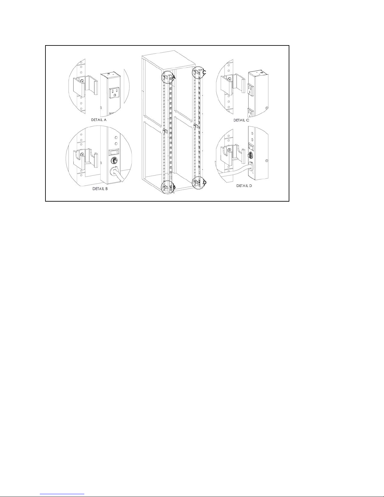
Top and Bottom Mounting Clips (9083C & 9084C)
Using the top and bottom mounting clips, attach the PDU to the rack as shown. Please note that
mounting clips are only intended for use with NSV and VSS Series PDUs.
GM1001.doc 13 Revision Date: 3/25/2009
Page 14

Optional Surge Suppression
The SP, SVR, and VSS Series PDUs
include a surge suppression circuit that
is designed to prevent voltage surges on
the input power line from reaching
devices powered by the PDU. The surge
suppression circuit uses Metal Oxide
Varistors (MOVs) connected between
Line, Neutral, and Ground wires to
prevent voltage surges from damaging
connected devices.
Surge Protection Circuit Ratings
Protection Voltage 330 V (Line-Line, Line-Neutral, Neutral-Ground)
Energy Absorption 720 Joules
Green Light Indicator Power On
Red Light Indicator Surge Protection Active
GM1001.doc 14 Revision Date: 3/25/2009
Page 15
Optional Local Monitoring
Power Meter
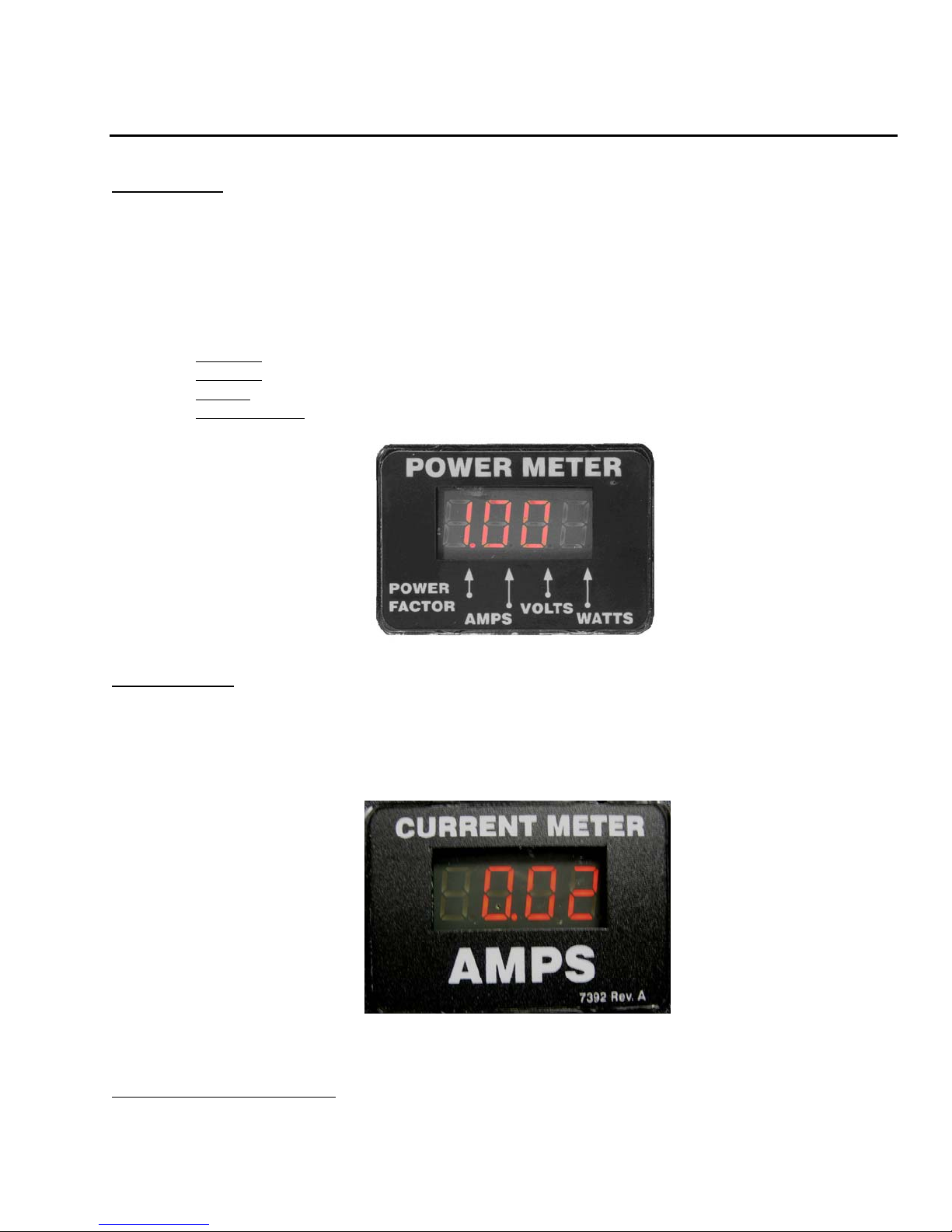
The Geist PM-1 power meter is a low-power, high accuracy meter capable of measuring true
RMS Current, Voltage, Power, and Power Factor. These values are individually shown on an
easy to read, 4-digit LED Display, which continuously scrolls through the four different
measured values. Each one of these displayed parameters is defined below. The Power Meter
will automatically begin cycling through the displayed values when the PDU is connected to AC
Mains power.
• Current:
• Voltage:
• Power:
• Power Factor:
PDU output current draw measured in true RMS Amps
PDU output voltage measured in true RMS Voltage
PDU output power measured in Watts – referred to as real or active power
Ration of real PDU output power to apparent PDU output power2
Power Meter Display
Current Meter
The Geist CM-1 current meter is a low-power, high accuracy meter capable of measuring true
RMS Current. The value of current is continuously shown on an easy to read, 4-digit LED
Display. The Current Meter will automatically begin to display value of output current when the
PDU is connected to AC Mains power.
Current Meter Display
2
Real power is the power in a circuit that is transformed from electric to non-electric energy, while
apparent power is the total power supplied to the circuit.
GM1001.doc 15 Revision Date: 3/25/2009
Page 16

Service/Tech Support
Service and Maintenance
No service or maintenance is required. Do not attempt to open the PDU or you may void the
warranty. No serviceable parts inside. It is recommended that power be removed from the
unit before installing or removing any equipment.
More Technical Support
http://www.geistmfg.com
(800) 432-3219
Email: [email protected]
Or contact your distributor.
GM1001.doc 16 Revision Date: 7/1/2009
Page 17

Table of Figures
Full Length Bracket...................................................................................................................................................................6
Mini "L" Brackets (SLB-4)......................................................................................................................................................6
Vertical Extension Brackets (VCB-1)......................................................................................................................................7
Toolless Mounting Hardware (11621)......................................................................................................................................7
Toolless Full Length Bracket (TLFL)......................................................................................................................................8
Single Side Mount 2 Unit Brackets (TSMX2)...................................................................................... ...................................8
Offset/Side Mount Brackets (EZB-1).......................................................................................................................................9
7" Extension Brackets (XB-7)...................................................................................................................................................9
Flush Mount Brackets (FM)...................................................................................................................................................10
Adjustable Mount Brackets (AM)..........................................................................................................................................10
Panel Mount Brackets (PM)...................................................................................................................................................11
23" Conversion Mounting Brackets (23-RM).......................................................................................................................11
Cable Mount Bracket (CMB-1)..............................................................................................................................................12
19" Horizontal/Panel Mount Brackets (7938).......................................................................................................................12
Top and Bottom Mounting Clips (9083C & 9084C).............................................................................................................13
Power Meter Display...............................................................................................................................................................15
Current Meter Display............................................................................................................................................................15
GM1001.doc 17 Revision Date: 3/25/2009
Page 18

Revision History
Revision Date Notes Approved By
1.0 3/26/2009 Original Published Version JLP
GM1001.doc 18 Revision Date: 3/25/2009
 Loading...