

Page 1

R-Series v5
Instruction Manual
geistglobal.com
Page 2

2
R-Series v5 Instruction Manual
Table of Contents
Introduction
................................................................................................................................... 5Welcome
About this Manual
................................................................................................................................... 8Revision History
................................................................................................................................... 8Organization of the Manual
................................................................................................................................... 8Audience Profile
................................................................................................................................... 8On-line Documentation
................................................................................................................................... 9Reporting Document Errors
................................................................................................................................... 9Conventions
.......................................................................................................................................................... 9Softw are
.......................................................................................................................................................... 9Hardware
.......................................................................................................................................................... 11Safety
.......................................................................................................................................................... 12Figures
.......................................................................................................................................................... 12Tables
Chapter 1 - Product Specifications
................................................................................................................................... 13Product Specifications
.......................................................................................................................................................... 13Overview
.......................................................................................................................................................... 13Environmental
......................................................................................................................................................... 13Temperature
......................................................................................................................................................... 14Humidity
......................................................................................................................................................... 14Elevation
.......................................................................................................................................................... 14Electrical
......................................................................................................................................................... 14Receptacle Ratings
.......................................................................................................................................................... 14Networking
......................................................................................................................................................... 15Ethernet
......................................................................................................................................................... 15Protocols
......................................................................................................................................................... 15User Interfaces
.......................................................................................................................................................... 16Re gulator y Com pliance
......................................................................................................................................................... 16Underw riters Laboratories (UL)
......................................................................................................................................................... 16CE
......................................................................................................................................................... 16Federal Communications Commission (FCC)
......................................................................................................................................................... 17RoHS/WEEE
5
7
13
Chapter 2 - Installation
................................................................................................................................... 18Pre-Installation
................................................................................................................................... 19Installation
.......................................................................................................................................................... 19Mounting
......................................................................................................................................................... 20Full Length Brackets
......................................................................................................................................................... 21Mini "L" Brackets (SLB-4)
......................................................................................................................................................... 21Vertical Extension Brackets (VCB-1)
......................................................................................................................................................... 22Toolless Mounting Hardw are (11621)
GM1196 R-Ser ies v5 Instruction Manual
18
© 2018 Geist
Page 3

......................................................................................................................................................... 22Toolless Full Length Brackets (TLFL)
......................................................................................................................................................... 23Single Side Mount 2 Unit Brackets (TSMX2)
......................................................................................................................................................... 23Offset/Side Mount Brackets (EZB-1)
......................................................................................................................................................... 247" Extension Brackets (XB-7)
......................................................................................................................................................... 24Flush Mount Brackets (FM)
......................................................................................................................................................... 25Adjustable Mount Brackets (AM)
......................................................................................................................................................... 25Panel Mount Brackets (PM)
......................................................................................................................................................... 2623" Conversion Mounting Brackets (23-RM)
......................................................................................................................................................... 26Cable Mount Brackets (CMB-1)
......................................................................................................................................................... 2719" Horizontal/Panel Mount Brackets (7938)
.......................................................................................................................................................... 28Ne tw or k Se tup
3Table Of Contents
Chapter 3 - Setup
................................................................................................................................... 33Hardware Interface
................................................................................................................................... 34Web Interface
................................................................................................................................... 35Sensors
.......................................................................................................................................................... 35Overview
......................................................................................................................................................... 37Configuration and Operation
.......................................................................................................................................................... 42Alarm s & War nings
......................................................................................................................................................... 43Alarms & Warnings Configuration
.......................................................................................................................................................... 46Logging
................................................................................................................................... 48System
.......................................................................................................................................................... 48Users
.......................................................................................................................................................... 53Network
.......................................................................................................................................................... 58Web Se rve r
.......................................................................................................................................................... 60Reports
.......................................................................................................................................................... 61LDAP
.......................................................................................................................................................... 63Display
.......................................................................................................................................................... 64Time
.......................................................................................................................................................... 64SSH
.......................................................................................................................................................... 64Email
.......................................................................................................................................................... 66SNMP
.......................................................................................................................................................... 68Syslog
.......................................................................................................................................................... 69Admin
.......................................................................................................................................................... 70Locale
.......................................................................................................................................................... 70Utilities
................................................................................................................................... 73Help
.......................................................................................................................................................... 73Info
.......................................................................................................................................................... 73Suppor t Site
................................................................................................................................... 74Communication
.......................................................................................................................................................... 74Ser ial Inte rface
......................................................................................................................................................... 74Setup
......................................................................................................................................................... 74Communication
................................................................................................................................... 76Technical Support
.......................................................................................................................................................... 76Re se ttin g PDU
.......................................................................................................................................................... 76Ser vice and M ainten ance
.......................................................................................................................................................... 77Using M icrosoft Exchange as an SMTP s erver
33
Chapter 4 - Final Checkout
................................................................................................................................... 79Product-Specific Safety Notices
.......................................................................................................................................................... 79Gene ral Safe ty
GM1196 R-Ser ies v5 Instruction Manual
79
© 2018 Geist
3
Page 4

4
R-Series v5 Instruction Manual
.......................................................................................................................................................... 79Live Cir cuits Safety
.......................................................................................................................................................... 80Equipm e nt Gro unding
.......................................................................................................................................................... 80Elect ros tatic Dischar ge
.......................................................................................................................................................... 80Explos ive Environm e nt
.......................................................................................................................................................... 80Ser vicing and Adjus tm ent s
.......................................................................................................................................................... 80Re pairs and M odifications
GM1196 R-Ser ies v5 Instruction Manual
© 2018 Geist
Page 5

Introduction
Welcome
Notice to Users
Geist, a division of Vertiv, Inc., reserves the right to make changes to this
document without notice to any user or reseller of this product. Geist, a
division of Vertiv, Inc., also reserves the right to substitute or terminate
distribution of this document, with no obligation to notify any person or party
of such substitutions or terminations.
Copyrights
© 2018 - Geist, a division of Vertiv, Inc. All Rights Reserved.
Introduction 5
Trademarks
All Trademarks contained herein are registered to Geist, a division of Vertiv,
Inc.
Use and Disclosure Restrictions
The software and documentation contained in this publication are
copyrighted materials.
Recovery Act Buy American
Geist products adhere to the Buy American provisions of the American
Recovery and Reinvestment Act of 2009 (Recovery Act). All Geist goods
manufactured in our Lincoln, Nebraska, plant have undergone substantial
transformation during production.
Trade Agreements Act (TAA)
Geist goods manufactured in our Lincoln, Nebraska, plant have undergone
substantial transformation during production. These Geist products adhere
to U.S. Trade Agreements Act and can be supplied for GSA Schedules and
other government contracts.
GM1196 R-Ser ies v5 Instruction Manual
© 2018 Geist
Page 6

R-Series v5 Instruction Manual6
Geist Policy on Conflict Minerals
This document details Geist’s corporate policy regarding the use of conflict
minerals. The policy expressed in this document should be considered to
cover the Geist and Geist Europe divisions of Vertiv Inc.
Section 1502 of the Dodd-Frank Act which was passed by the US Congress
in 2010 requires certain companies to annually disclose their use of conflict
minerals. Conflict minerals covered under this act include tantalum, tin,
tungsten, and gold.
Although Geist is not directly subjected to the requirements of the DoddFrank Act, Geist recognizes that all companies within the electronics
manufacturing industry supply chain are impacted by this legislation. Geist
supports the intent of the law, which is the reduction of violence within the
Democratic Republic of the Congo and will take several actions to both
advance the goals of the Dodd-Frank Act and to provide exceptional
support to our customers.
· Geist will work with our direct suppliers to identify purchased components
and materials that contain tin, tantalum, tungsten or gold.
· Geist will work with our direct suppliers to trace sources of any tin,
tantalum, tungsten or gold used in our products back to the smelter.
· Geist will document our efforts to trace tin, tantalum, tungsten, and gold
minerals back to the smelter and will accurately report the results to our
customers.
· Geist will continue to monitor industry progress in identifying conflict-free
smelters and will adjust corporate policy as the electronics supply chain
becomes more fully documented.
GM1196 R-Ser ies v5 Instruction Manual
Geist will not require that our direct suppliers source only conflict-free
minerals until an adequate number of smelters has been reliably identified
and audited by The Electronic Industry Citizenship Coalition (EICC) and the
Global e-Sustainability Initiative (GeSI) to service the electronic industry
supply chain. Mandating a conflict-free supply chain before an adequate
number of smelters has been identified will prohibit the use of all tin,
tantalum, tungsten, and gold originating in the Democratic Republic of the
Congo and surrounding countries. This prohibition would cut off the sole
income source for many artisanal miners within the region and may result in
increased violence within the Democratic Republic of the Congo in direct
opposition to the goals of the Dodd-Frank Act. Geist will work continuously
with our direct suppliers in order to annually increase the percentage of
documented conflict-free minerals that are used in our products until all
products can be certified as conflict-free.
© 2018 Geist
Page 7

Introduction 7
WEEE Declaration
Geist Europe is obligated to finance the cost of the collection, treatment,
recovery and environmentally sound disposal of all products sold by Geist
Europe into the UK market this includes:
· New WEEE (displaying ‘the crossed out wheeled bin symbol’) that Geist
Europe has placed onto the market after the 13th August 2005; and
· Historic WEEE (not displaying ‘the crossed out wheeled bin symbol’), when
Geist Europe is supplying new WEEE that is intended to replace the
historic WEEE and is of equivalent type or fulfills the same function even if
the historic WEEE was manufactured by a third party.
Please contact Geist Europe on 01823 275100 for further details or to
arrange collection. (UK Only)
Document Usage
All reasonable efforts have been made to assure the accuracy of this
document from any technical or typographical errors or omissions. Geist, a
division of Vertiv, Inc., and its affiliates disclaim responsibility for any labor,
materials, or costs incurred as a result of usage of this document. Nor shall
Geist, a division of Vertiv, Inc., and its affiliates be liable for any damages,
inclusive of loss of profits or data, arising from the use of or in connection
with this document.
Geist, a division of Vertiv, Inc., reserves the right to make changes to this
document without notice to any user or reseller of this product. Geist, a
division of Vertiv, Inc., also reserves the right to substitute or terminate
distribution of this document, with no obligation to notify any person or party
of such substitutions or terminations.
About this Manual
This document provides an overview of Geist product(s), the major topics
covered include:
· Copyright, Trademarks, and Disclosure Restrictions.
· Instructions for installing, powering and using the equipment.
· Information that will aid in managing and maintaining the equipment.
GM1196 R-Ser ies v5 Instruction Manual
© 2018 Geist
Page 8

R-Series v5 Instruction Manual8
Revision
Date
Notes
Approved By
1.0
3/16/2017
New manual for v5 firmware
SC
2.0
8/04/2017
Minor updates
SC
3.0
12/15/2017
Update for v5.2 release
SC
3.1
3/22/2018
Vertiv, UL, and CE updates
JB
3.2
5/9/2018
RoHS Statement Update
JB
Revision History
Organization of the Manual
This Geist document contains the following product information:
· Product Specifications - This chapter describes the major product
characteristics and its functional role within the system. Where appropriate,
reference to cabling among product components and to other Geist
product(s) is provided.
· Installation - This chapter provides installation information for the preparation
and use of Geist products as well as procedures required to adequately
mechanically and electrically attach Geist product into supporting systems.
· Setup - This chapter provides instructions on power-up procedures after
product installation and configuration of the software and features.
· Final Checkout - Technical Support guidelines and safety information are
provided in this chapter.
Audience Profile
This document is intended for use by authorized technicians experienced with
same of similar product types and for personnel requiring guidance for equipment
installation, operation, maintenance, and support.
On-line Documentation
This document is available on-line and within the corresponding Geist Product
Manuals. Additional Geist product supporting Videos, Product Literature and
Case Studies can be found on the Geist Resource page.
GM1196 R-Ser ies v5 Instruction Manual
© 2018 Geist
Page 9

Product firmware updates can be found and downloaded from the Geist Support
site, under Firmware Updates.
Should this product fail within its warranty period and be in need of repair or
replacement, a Return Material Authorization may be obtained on-line from the
RMA Form link located within the Geist Support site.
Reporting Document Errors
Should you discover any error or identify a deficiency in this document, please
take time to contact us at the following email address:
Please be sure to provide us with the document name, part number, and page
number(s). Also, please provide us with description of the error or the deficiency
for the document. If you would like for us to contact you, please provide us with
your name and contact information.
About this Manual 9
Thank you for your time. We appreciate any comments and feedback you can
provide.
Conventions
The information contained within this document is established around the
framework of various conventions, which are defined as follows:
Software
· Release Management: Product name, Version control
Hardware
Product Classification
o Product Name: Name of Hardware Platform
o Version control: V(ersion) Platform #, Major #, Minor #
§ Example: GU v3.0.0
o Power Distribution Unit
§ Basic
§ Metered only
§ Monitored only
§ Switched only
§ Monitored + Switched
o Environmental Monitoring
§ Standard
§ Wireless
GM1196 R-Ser ies v5 Instruction Manual
© 2018 Geist
Page 10

R-Series v5 Instruction Manual10
o Cooling
§ Passive
§ Active
o Data Center Infrastructure Management (DCIM)
Figure 1 Overlay Symbology Guide
GM1196 R-Ser ies v5 Instruction Manual
© 2018 Geist
Page 11

Safety
DANGER
INDICATES AN IMMINENT HAZARDOUS SITUATION
WHICH, IF NOT AVOIDED, WILL RESULT IN DEATH OR
SERIOUS INJURY.
WARNING
INDICATES A POTENTIAL HAZARDOUS SITUATION WHICH, IF
NOT AVOIDED, COULD RESULT IN DEATH OR SERIOUS
INJURY.
CAUTION
INDICATES A POTENTIAL HAZARDOUS SITUATION WHICH, IF
NOT AVOIDED, COULD RESULT IN PRODUCT DAMAGE AND
MINOR TO MODERATE INJURY.
NOTE
Provides useful information that is beneficial for operation and
usage of this product.
About this Manual 11
This document contains varying levels of alerts pertaining to product and user
safety. The alerts are visually presented with graphics and text per Geist
equipment guidelines.
The representations are:
GM1196 R-Ser ies v5 Instruction Manual
© 2018 Geist
Page 12

R-Series v5 Instruction Manual12
Column 1
Column 2
Column 3
Column 4
Column 5
Text
Text
Text
Text
Text
Text
Text
Text
Text
Text
Text
Text
Text
Text
Text
Text
Text
Text
Text
Text
Figures
Figures presented in this document are identified and designated
as follows:
'Figure:', Chapter # - Image #
Example:
Figure 1-1 Name and/or Title goes here
Tables
Tables presented in this document are identified and designated as follows:
'Table:', Chapter # - Image #
Example:
Table 1-1 Name and/or Title goes here
GM1196 R-Ser ies v5 Instruction Manual
© 2018 Geist
Page 13

About this Manual 13
Input Power
Monitoring
Outlet Level Power
Monitoring
Outlet Level
Switching
RCX
RCO
RCM-O
RCU-O
Minimum
Maximum
Operating
10°C (50°F)
45°C (113°F)
Storage
-25°C (13°F)
65°C (149°F)
Chapter 1 - Product Specifications
Product Specifications
Overview
The R-Series are rack level power distribution units (PDUs) with monitoring via a built-in
web server. Web pages, including logging, are generated by the unit to monitor power and
environmental conditions within the cabinet, several data formats are available. R-Series
PDUs support optional external sensors. These units can be built for installation in singlephase, three-phase Delta or Wye building wiring configurations. There are four families
within the R-Series; RCX, RCO, RCM-O and RCU-O
Table 1-1 R-Series Families
Environmental
The operational environmental limits pertaining to Temperature, Humidity and
Elevation are as defined below.
Temperature
Table 1-2 Temperature Limits
GM1196 R-Ser ies v5 Instruction Manual
© 2018 Geist
Page 14

R-Series v5 Instruction Manual14
Minimun
Maximum
Operating
5%
95% (non-condensing)
Storage
5%
95% (non-condensing)
Minimun
Maximum
Operating
0 m (0 ft)
2,000 m (6,500 ft)
Storage
0 m (0 ft)
15,240 m (50,000 ft)
Type
Ratings
NEMA 5-15R or L5-15R
125Vac, 12A
NEMA 5-20R or L5-20R
125Vac, 16A
NEMA 6-20R or L6-20R
250Vac, 16A
NEMA L5-30R
125Vac, 24A
NEMA L6-30R
250Vac, 24A
IEC-60320 C13
250Vac, 10A (UL & CSA 12A, 250Vac)
IEC-60320 C19
250Vac, 16A (UL & CSA 16A, 250Vac)
Humidity
Table 1-3 Humidity Limits
Elevation
Table 1-4 Elevation Limits
Electrical
Electrical product characteristics an performance are defined below. Also, please
see the product nameplate for additional rating limits.
Receptacle Ratings
Table 1-5 Receptacle Ratings
Networking
The product communications requirements are identified below.
GM1196 R-Ser ies v5 Instruction Manual
© 2018 Geist
Page 15

Chapter 1 - Product Specifications 15
Ethernet
The Ethernet link speed for this product is: 10/100 Mb; full duplex.
Protocols
The communications protocols supported by this product include:
ARP, IPv4, IPv6, ICMP, ICMPv6, NDP, TCP, UDP, DNS, HTTP, HTTPS
(TLSv1.2), SMTP, SMTPS, DHCP, SNMP (v1/v2c/v3), LDAP, NTP, SSH, and
Syslog.
User Interfaces
This product supports the following user interfaces:
SNMP, JSON-based Web GUI, and Command-line interface using SSH or
Serial (RS-232).
GM1196 R-Ser ies v5 Instruction Manual
© 2018 Geist
Page 16

R-Series v5 Instruction Manual16
Regulatory Compliance
Geist products are regulated for Safety, Emissions, and Environment Impact per the below
agencies and policies.
Underwriters Laboratories (UL)
UL Standards are used to assess products; test components, materials, systems and
performance; and evaluate environmentally sustainable products, renewable energies,
food and water products, recycling systems and other innovative technologies.
The UL standards specific to this equipment are listed in the UL Online Certification Library
under the file number noted on the device name plate.
CE
The placement of the CE mark on a product signifies a manufacturer's declaration that the
product complies with the applicable European (EU) health, safety, and environmental
protection requirements, including EU legislation and product directives. The CE mark is
required for products offered for sale within the European Economic Area (EEA).
The specific regulations, directives, and standards applicable to each product are
specified on the Declaration of Conformity.
Federal Communications Commission (FCC)
The Federal Communications Commission (FCC) regulates interstate and international
communications by radio, television, wire, satellite, and cable in all 50 states, the District of
Columbia and U.S. territories. An independent U.S. government agency overseen by
Congress, the commission is the United States' primary authority for communications
laws, regulation and technological innovation.
The FCC standards specific to this equipment are:
This Class A device complies with part 15 of the FCC Rules. Operation is subject to the
following two conditions:
(1) This device may not cause harmful interference
(2) This device must accept any interference received, including interference that
may cause undesired operation.
This Class A digital apparatus complies with Canadian ICES-003.
Cet appareil numérique de la classe A est conforme à la norme NMB-003 du Canada.
GM1196 R-Ser ies v5 Instruction Manual
© 2018 Geist
Page 17

Chapter 1 - Product Specifications 17
WARNING
Changes or modifications to this unit not expressly approved by
the party responsible for compliance could void the user’s
authority to operate this equipment.
Restricted Substance
Maximum Concentration Value
(w/w)
Cadmium (Cd):
0.01%
Mercury (Hg):
0.10%
Lead (Pb):
0.10%
Hexavalent chromium (Cr6+):
0.10%
Polybrominated biphenyls (PBB):
0.10%
Polybrominated diphenyl ethers
(PBDE):
0.10%
**Bis(2-Ethylhexyl) phthalate (DEHP):
0.10%
**Butyl Benzyl phthalate (BBP):
0.10%
**Dibutyl phthalate (DBP):
0.10%
**Diisobutyl phthalate (DIBP):
0.10%
NOTE
DEHP, BBP, DBP, and DIBP restrictions are in effect as of July
2019.
RoHS/WEEE
Directive 2011/65/EU outlines the restriction of the use of hazardous substances in
electrical and electronic equipment (EEE) with a view to contributing to the protection of
human health and the environment, including the environmentally sound recovery and
disposal of waste EEE.
Restricted substances and their respective maximum concentration values are listed
below.
GM1196 R-Ser ies v5 Instruction Manual
© 2018 Geist
Page 18

R-Series v5 Instruction Manual18
NOTE
(Note: load up to full nameplate rating are permitted during
short term abnormal operating conditions).
Chapter 2 - Installation
Pre-Installation
· For standard temperature models, the ambient temperature of the installation
location, such as an IT rack, should be no greater than 45°C if the PDU is loaded
to its full nameplate current rating. The ambient temperature of the installation
location should be not greater than 60°C if the PDU normal current load is a
maximum 50% of the nameplate and individual receptacle ratings.
· Install the PDU such that the amount of airflow required for safe operation of
equipment is not compromised.
· Mount the PDU so that a hazardous condition is not achieved due to uneven
mechanical loading.
· Follow nameplate ratings when connecting equipment to the branch circuit. Take
into consideration the effect that overloading of the circuits might have on
overcurrent protection and supplied wiring.
· The PDU relies on the building installation for protection from overcurrent. A
certified overcurrent protection device is required in the building installation. The
overcurrent protection device should be sized according to the PDU’s nameplate
ratings and local/national electrical code.
· Reliable earthing of rack-mount equipment should be maintained. Particular
attention should be given to supply connections other than direct connections to
the branch circuit. The PDU must be connected to an earthed socket outlet.
· PDU is intended for restricted-access locations. Only qualified service personnel
should install and access the PDU.
· For pluggable equipment, install the PDU so the input plug or appliance coupler
may be disconnected for service.
· The PDU is intended for indoor use only. Do not install the unit in wet or outdoor
environments, and do not install it next to water tanks or plumbing.
· The PDU is intended for use with TN, TT, or IT power supply systems.
GM1196 R-Ser ies v5 Instruction Manual
© 2018 Geist
Page 19

Chapter 2 - Installation 19
Installation
1. Using appropriate hardware, mount unit to rack. See next section for examples.
2. Plug PDU into an appropriately-rated and protected branch-circuit receptacle.
3. Plug in the devices to be powered by the PDU.
4. Turn on each device connected to the PDU. Sequential power-up is recommended to
avoid high inrush current.
Mounting
Optional brackets sold separately.
1. Using appropriate hardware, mount unit to rack. (See below examples.)
2. Plug PDU into an appropriately-rated and protected branch-circuit receptacle.
3. Plug in the devices to be powered by the PDU.
4. Turn on each device connected to the PDU. Sequential power-up is recommended to
avoid high inrush currents.
GM1196 R-Ser ies v5 Instruction Manual
© 2018 Geist
Page 20

R-Series v5 Instruction Manual20
Full Length Brackets
Figure 2-1 Full Length Bracket
GM1196 R-Ser ies v5 Instruction Manual
© 2018 Geist
Page 21

Mini "L" Brackets (SLB-4)
Figure 2-2 Mini L Brackets
Chapter 2 - Installation 21
Vertical Extension Brackets (VCB-1)
Figure 2-3 Vertical Extension Brackets
GM1196 R-Ser ies v5 Instruction Manual
© 2018 Geist
Page 22

R-Series v5 Instruction Manual22
Toolless Mounting Hardware (11621)
Figure 2-4 Toolless Mounting Hardware
Toolless Full Length Brackets (TLFL)
Figure 2-5 Toolless Full Length Brackets
GM1196 R-Ser ies v5 Instruction Manual
© 2018 Geist
Page 23

Single Side Mount 2 Unit Brackets (TSMX2)
Figure 2-6 Single Side Mount 2 Units Brackets
Chapter 2 - Installation 23
Offset/Side Mount Brackets (EZB-1)
Figure 2-7 Offset/Side Mount Brackets
GM1196 R-Ser ies v5 Instruction Manual
© 2018 Geist
Page 24

R-Series v5 Instruction Manual24
7" Extension Brackets (XB-7)
Figure 2-8 7" Extension Brackets
Flush Mount Brackets (FM)
Figure 2-9 Flush Mount Brackets
GM1196 R-Ser ies v5 Instruction Manual
© 2018 Geist
Page 25

Adjustable Mount Brackets (AM)
Figure 2-10 Adjustable Mount Brackets
Chapter 2 - Installation 25
Panel Mount Brackets (PM)
Figure 2-11 Panel Mount Brackets
GM1196 R-Ser ies v5 Instruction Manual
© 2018 Geist
Page 26
R-Series v5 Instruction Manual26
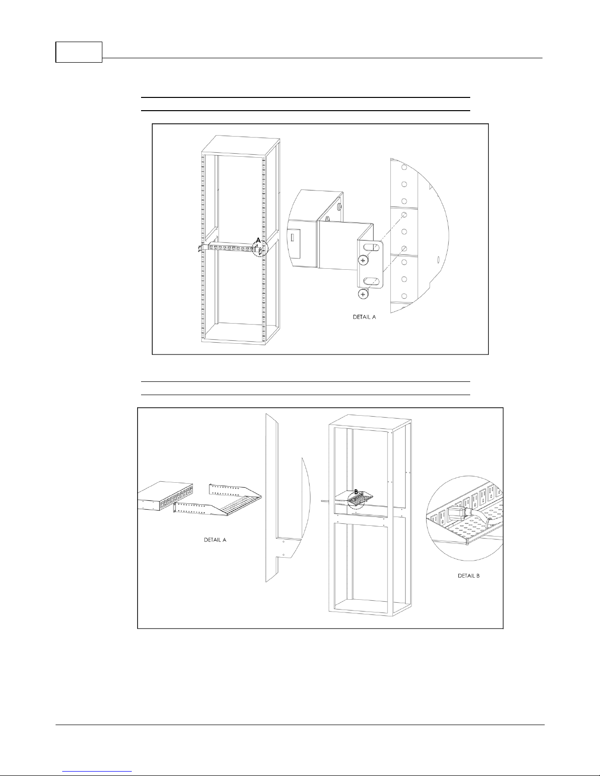
23" Conversion Mounting Brackets (23-RM)
Figure 2-12 23" Conversion Mounting Brackets
Cable Mount Brackets (CMB-1)
Figure 2-13 Cable Mount Brackets
GM1196 R-Ser ies v5 Instruction Manual
© 2018 Geist
Page 27
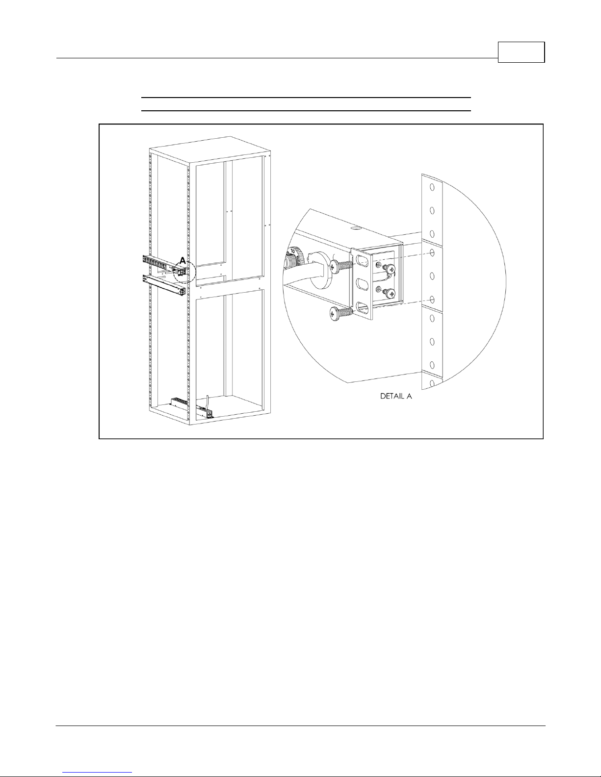
19" Horizontal/Panel Mount Brackets (7938)
Figure 2-14 19" Horizontal/Panel Mount Brackets
Chapter 2 - Installation 27
GM1196 R-Ser ies v5 Instruction Manual
© 2018 Geist
Page 28

R-Series v5 Instruction Manual28
IP Address:
192.168.123.123
Subnet Mask:
255.255.255.0
Gateway:
192.168.123.1
Network Setup
The Geist R-Series PDU has a default IP address for initial setup and access. Once you
have assigned an IP address, the default IP address will no longer be active. To restore
the default IP address and reset all user-account information, if the user-assigned address
or passwords are lost or forgotten, press and hold the network-reset button located
below the Ethernet port for 15 seconds. Holding the center button of the LED display for
10 seconds will also reset the network and user account information.
To completely erase ALL of the user settings and restore the unit back to its factorydefault state, disconnect power from the PDU, then press and hold the network-reset
button while powering up the PDU.
The Network page (located under the System Tab) allows you to assign the network
properties manually, or use DHCP to connect to your network. Access to the unit
requires the IP address to be known. Use of a static IP or a reserved DHCP is
recommended. The default address is shown on the front of the unit:
Table 2-1 Default IP Address
To access the unit for the first time, you will need to temporarily change your computer's
network settings to match the 192.168.123. xxx subnet. To set up the unit, connect it to
your computer's Ethernet port, then follow the appropriate instructions for your
computer's operating system.
Windows
· Windows 2000 / XP / Server 2003:
Click the Start button, choose Settings, then Network Connections.
· Windows 7 / Server 2008:
Click the Start button, then choose Control Panel >> Adjust Your Computer's Settings
>> View Network Status and Tasks >> Change Adapter Settings.
(Alternatively, on some Windows 7 machines, this may be Start, then Settings >> Control
Panel >> Network and Sharing Center >> Change Adapter Settings.)
· Windows 8 / Server 2012:
Move the mouse cursor to the bottom or top right corner of the screen, click the Settings
icon, then select Control Panel. Change the view type from Category to Large or Small
Icons if necessary, then select Network and Sharing Center, then Change Adapter
Settings.
· Windows 10:
Click the Start button, then choose Network & Internet, then click Change adapter
options.
GM1196 R-Ser ies v5 Instruction Manual
© 2018 Geist
Page 29
Chapter 2 - Installation 29
NOTE
Most computers will have a single Ethernet NIC installed, but a
WiFi or 3G adapter will also show as a NIC in this list, so be
sure to choose the correct entry.
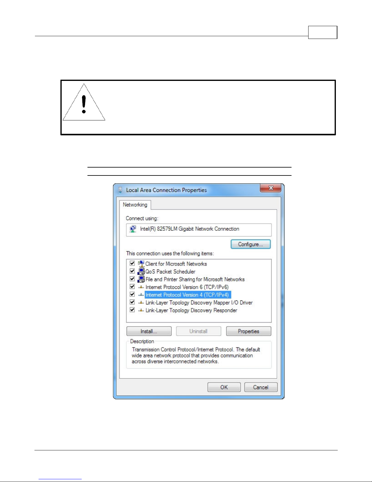
Locate the entry under LAN or High-Speed Internet or Local Area Connection which
corresponds to the network card (NIC).
Double-click on the network adapter's entry in the Network Connections list to open its
status dialog box, then click the Properties button to open the Local Properties window.
Figure 2-15 Local Area Connection Properties
Find the entry titled "Internet Protocol Version 4 (TCP/IPv4)" in the list, then click the
GM1196 R-Ser ies v5 Instruction Manual
Properties button to open the Internet Protocol Properties window. If you see more
© 2018 Geist
Page 30
R-Series v5 Instruction Manual30
than one TCP/IP entry, as in the example above, the computer may be configured for IPv6
support as well as IPv4; make sure to select the entry for the IPv4 protocol. Write down
the current NIC card settings so you can restore them to normal after you have completed
the setup procedure.
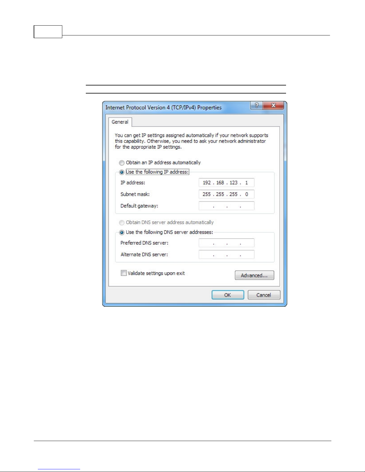
Figure 2-16 Internet Protocol Version 4
Choose the Use the following IP address option, then set IP address to 192.168.123.1
and Subnet Mask to 255.255.255.0. For this initial setup, Default Gateway and the DNS
Server entries can be left blank. Select OK, then OK again to close both the Internet
Protocol Properties and Local Properties windows.
Once the NIC settings are configured properly, you should be able to access the unit by
typing http://192.168.123.123 into the address bar of your web browser. If you are setting
up the unit for the first time, or if the unit has been reset back to factory defaults via the
network-reset button, the unit will require you to create an Admin account and password
before you can proceed.
Once you have created an Admin account and have logged into it, the unit's default
Sensors page should come up by default. Navigate to the System tab, then the Network
GM1196 R-Ser ies v5 Instruction Manual
© 2018 Geist
Page 31
Chapter 2 - Installation 31
page to configure the device's network properties. The unit's IP Address, Subnet Mask,
Gateway, and DNS settings can either be assigned manually, or acquired via DHCP.
Note that the new settings will take effect when the Save button is clicked. The browser
will no longer be able to reload the web page from the 192.168.123.123 address and will
probably display a "page not found" or "host unavailable" message. This behavior is
normal. Once you have finished configuring the unit's IP address, simply repeat the steps
above, and change the computer's Ethernet NIC card settings back to the ones you wrote
down prior to changing them, to restore its normal network and internet settings.
Mac
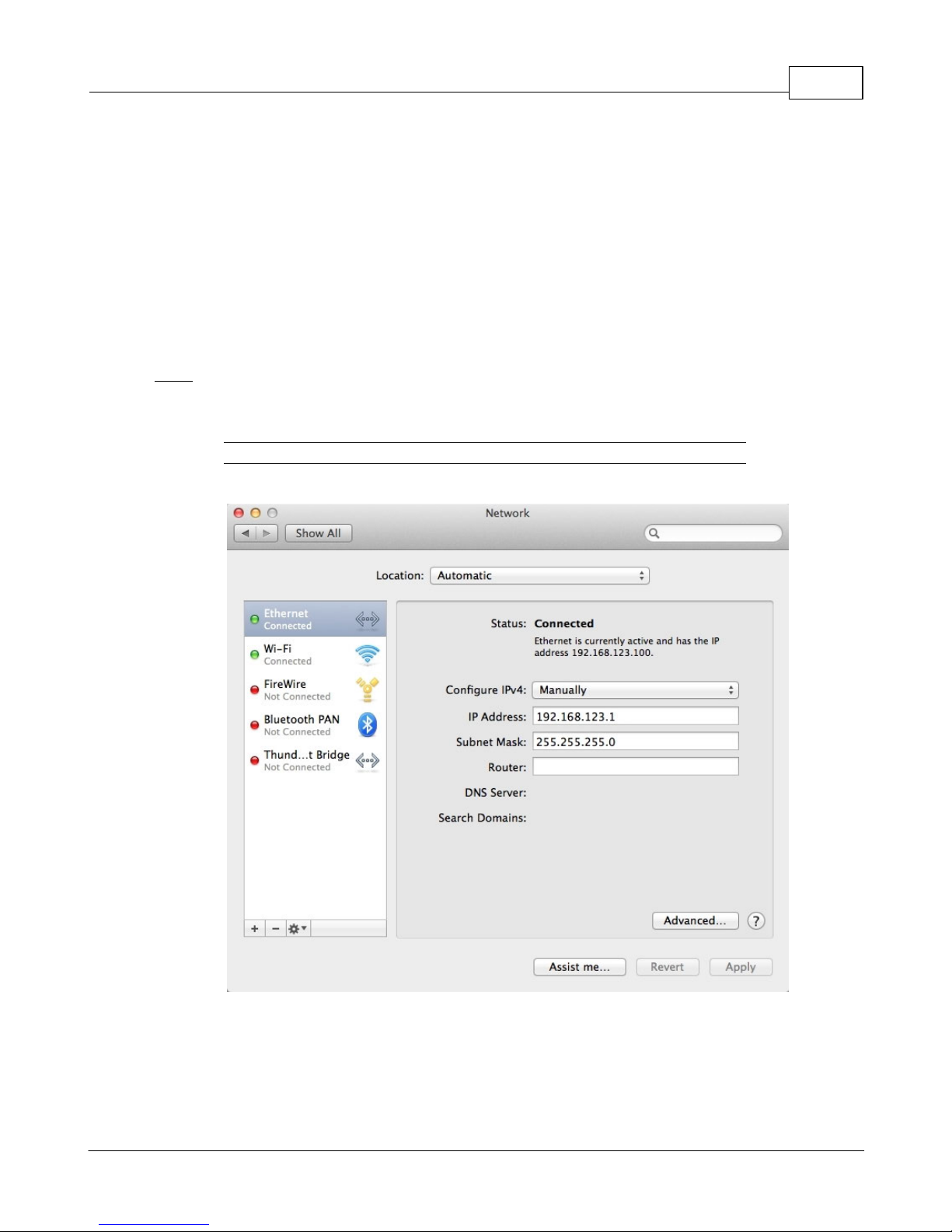
Click the System Preferences icon on the Dock, and choose Network.
Figure 2-17 Mac System Preferences
Be sure Ethernet is highlighted on the left side of the NIC window. In most cases, there
will be one Ethernet entry on a Mac. Write down the current settings so you can restore
them to normal after you have completed the setup procedure.
GM1196 R-Ser ies v5 Instruction Manual
© 2018 Geist
Page 32

R-Series v5 Instruction Manual32
Select Manually from the Configure IPv4 drop-down list, then set IP Address to
192.168.123.1 and Subnet Mask to 255.255.255.0. (The Router and DNS Server settings
can be left blank for this initial setup.) Click Apply when finished.
Once the NIC settings are configured properly, you should be able to access the unit by
typing http://192.168.123.123 into the address bar of your web browser. If you are setting
up the unit for the first time, or if the unit has been reset back to factory defaults via the
network-reset button, the unit will require you to create an Admin account and password
before you can proceed.
Once you have created the Admin account and logged into it, the unit's default Sensors
page should come up by default. Navigate to the System tab, then the Network page to
configure the device's network properties. The unit's IP Address, Subnet Mask, Gateway,
and DNS settings can either be assigned manually, or acquired via DHCP.
The new settings will take effect when the
Save
button is clicked, so the browser will no
longer be able to reload the web page from the 192.168.123.123 address and will probably
display a "page not found" or "host unavailable" message. This behavior is normal. Once
you have finished configuring the unit's IP address, simply repeat the steps above, and
change the computer's Ethernet NIC card settings back to the ones you wrote down prior
to changing them, to restore its normal network and internet settings.
GM1196 R-Ser ies v5 Instruction Manual
© 2018 Geist
Page 33
Chapter 2 - Installation 33
Chapter 3 - Setup
Hardware Interface
The R-Series PDUs have advanced features to support data center needs for full remote
monitoring, logging and alarms, with options for outlet level monitoring and switching
control. The PDUs support multiple I/O options.
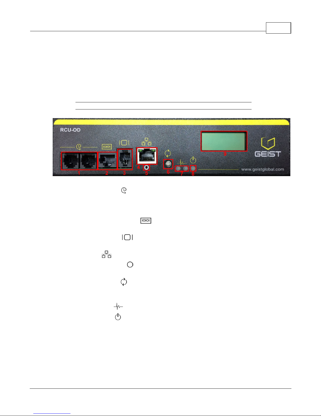
Figure 3-1 RCU-OD Interface
1. Remote Sensor Port ( ): Two RJ12 ports for connecting Geist plug-and-play remote
sensors (sold separately). Splitters may be used to increase the amount of sensors.
Each sensor has a unique serial number and is automatically discovered. R-Series
PDUs support up to sixteen sensors.
2. Serial Communication Port ( ): This RS-232 via RJ-45 port enables the R-Series
PDUs to provide serial access to the command line interface.
3. Remote Display Port ( ): An optional remote display (RSD2X8) can be connected
to the R-Series PDU.
4. Ethernet Port ( ): RJ45 port for connecting the PDU to a TCP/IP network.
5. Network-Reset Button ( ): Holding the network-reset button for 5 seconds during
normal operation will restore the default IP address and reset the user accounts.
6. Hard-Reboot Button ( ): Pressing the hard-reboot button reboots the monitoring
device. This acts as a power-cycle for the device, and does not change or remove any
user information. Note that this will NOT affect power to the outlets.
7. Activity/Idle LEDs ( )
8. Power Status LED ( )
9. Local LCD Display: The local display scrolls through the values of the measurements
selected on the LCD Display page.
For R-Series Switched PDUs, there is an LED next to each outlet providing feedback for
the current state.
· Green: Outlet is on.
· Red: Outlet is off.
GM1196 R-Ser ies v5 Instruction Manual
© 2018 Geist
Page 34
R-Series v5 Instruction Manual34
NOTE
An administrator account (username and password) must be
created when logging onto the device for the first time.
Web Interface
The Geist R-Series PDUs come with an embedded web interface. The unit is accessible
via a standard, unencrypted HTTP connection, or via an encrypted HTTPS (SSL)
connection.
GM1196 R-Ser ies v5 Instruction Manual
© 2018 Geist
Page 35
Chapter 3 - Setup 35
Sensors
Overview
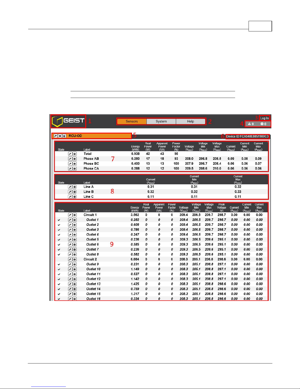
The Sensors Overview page displays the PDU's data. R-Series PDUs measure power,
voltage, current and energy. Readings on the Overview page are provided in real-time for
all of the unit's measurements.
Figure 3-2 RCU-OD Sensor Page
1. Geist Logo
· Clicking on this logo from any page will reload the Sensor Overview page.
GM1196 R-Ser ies v5 Instruction Manual
© 2018 Geist
Page 36
R-Series v5 Instruction Manual36
Sensors
System
Help
Overview
Users
Display
Syslog
Info
Alarms &
Warnings
Network
Time
Admin
Support Site
Logging
Web Server
SSH
Locale
Reports
Email
Utilities
LDAP
SNMP
2. Sensors, System, and Help Tabs
· Mouse over to show sub-menus:
Table 3-1 Sensors, System, and Help Tabs
3. Log In / Log Out
· Click to log in or log out of the unit. Note that both user-name and password are
case sensitive; prohibited characters are: $&`:<>[ ] { }"+%@/ ; =?\^|~',
4. Alarms and Warnings
· Indicates the number of Alarms and Warnings currently occurring, if any.
5. Device Label
· Displays the user-assigned label of this unit (see "Configuration and Operation")
6. Device ID
· Unique product identification. May be required for technical support.
7. Total and Individual Phase or Line Monitor
· Displays AC current, voltage, and power statistics for each individual phase, phase
pair, and for the total of all phases combined.
8. Line Current
· Displays AC line current draw for 3-phase Delta PDUs.
9. Circuit and Outlet
· Displays AC current, voltage and power statistics for each circuit and outlet. (Outlet
Level Power Monitoring and Switched Outlet Level Monitoring Only)
· Displays outlet status. (Switched and Switched Outlet Level Monitoring Only)
GM1196 R-Ser ies v5 Instruction Manual
© 2018 Geist
Page 37
NOTE
Groupings for Total, Line and Phase Monitor will vary depending
on the PDU's configuration and wiring.
Configuration and Operation
NOTE
Only users with control or admin level authorizations have
access to these settings.
Configuration Icon Operation Icon
Chapter 3 - Setup 37
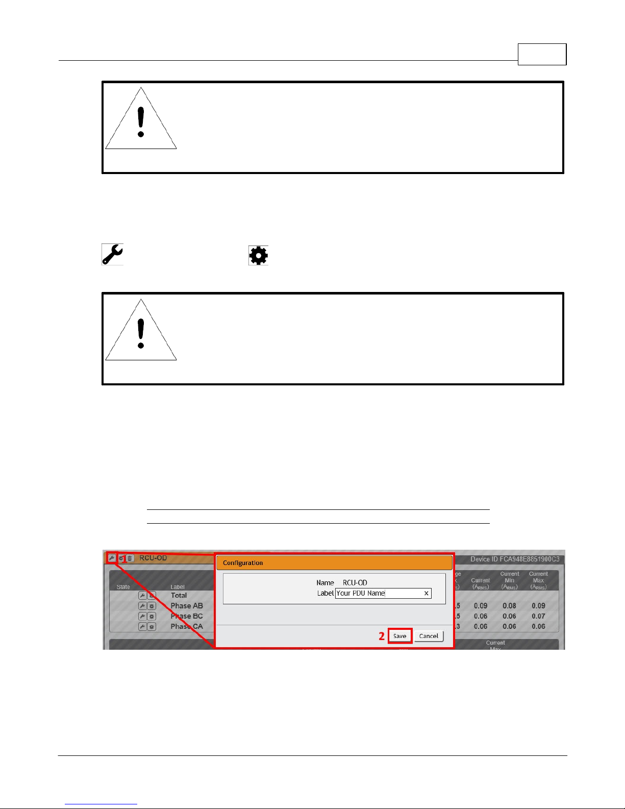
Device, Phase and Circuit Configuration:
1. Click the desired Configuration icon to change the device's Label. Name is the PDU's
factory name or model, and cannot be changed.
2. Once done, click Save.
Figure 3-3 Device, Phase and Circuit Configuration Page
GM1196 R-Ser ies v5 Instruction Manual
© 2018 Geist
Page 38
R-Series v5 Instruction Manual38
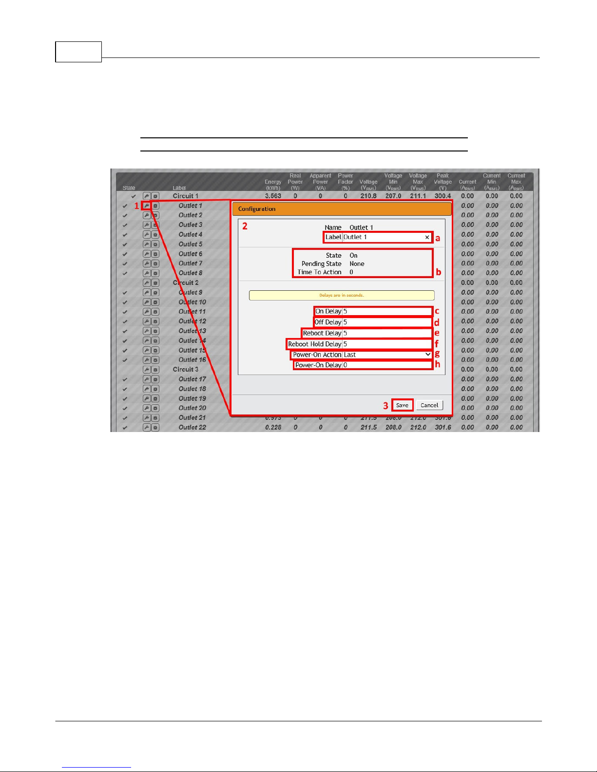
Outlet Configuration:
1. Click the desired Outlet Configuration icon.
Figure 3-4 Outlet Configuration Page
2. Configuration pop-up box will appear.
a. Use the text box to change the outlet's Label.
b. The outlet's state is described by three descriptors:
· State describes the outlet's current state (On/Off).
· Pending State describes the state the outlet is currently transitioning to, if it is in
the process of switching.
· Time To Action describes the time left before the pending action will take place.
This is adjusted using Delays.
c. On Delay is the time, in seconds, the unit waits before switching an outlet on.
d. Off Delay is the time, in seconds, the unit waits before switching an outlet off.
e. Reboot Delay is the time, in seconds, the unit waits before rebooting an outlet.
f. Reboot Hold Delay is the time, in seconds, the unit waits after switching the outlet
off, before switching an outlet back on during a reboot.
GM1196 R-Ser ies v5 Instruction Manual
© 2018 Geist
Page 39
Chapter 3 - Setup 39
CAUTION
These actions affect the entire device.
g. Power-On Action describes the state the outlet will start at power-on (On, Off or
Last).
h. Power-On Delay is the time, in seconds, the unit waits after power-on before
performing the power-on action for the outlet.
3. Click the Save button if any settings are changed.
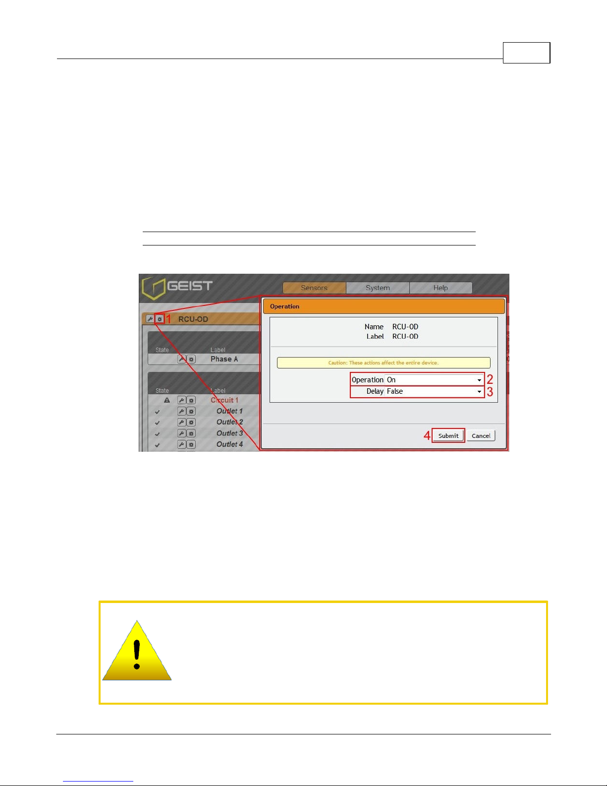
Device Operation:
1. Click the Operation icon.
Figure 3-5 Device Operation Page
2. Select the operation you wish to perform:
· On/Off turns on/off all outlets.
· For outlets currently on, Reboot cycles the outlets off, then back on after the reboot
hold delay. For outlets currently off, Reboot turns the outlets on.
· Cancel will cancel the current operation if it has not been completed yet.
· Reset Energy will reset the total Energy measured in kWh.
GM1196 R-Ser ies v5 Instruction Manual
© 2018 Geist
Page 40
R-Series v5 Instruction Manual40
NOTE
Power-on action delays reference the time since the unit was
plugged in, not the time since it fully booted. They may execute
before the unit fully boots.
3. For operations involving the state of the outlets, setting Delay to True will use the
current Delay configuration for each outlet when performing the selected operation.
4. Select Submit to issue the action.
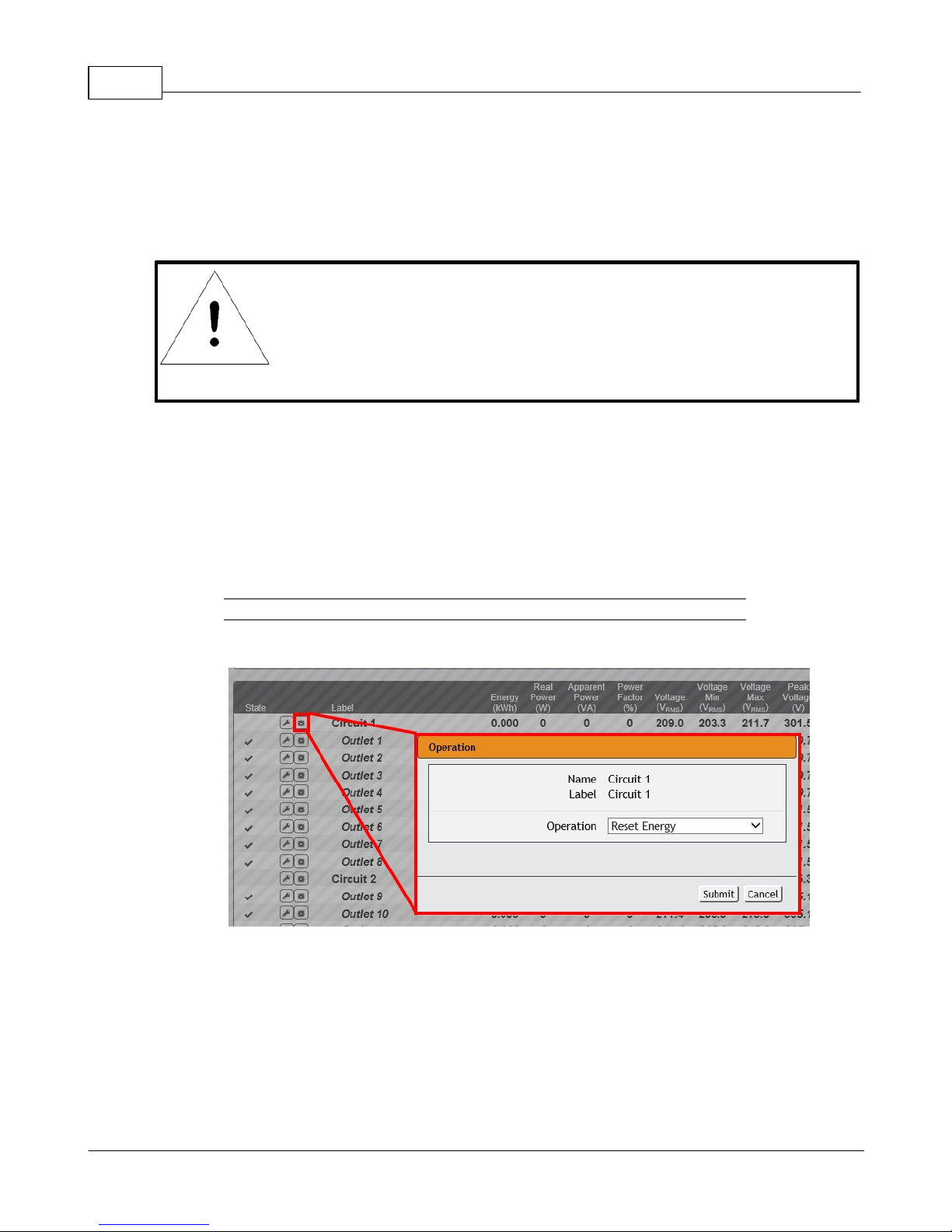
Phase/Circuit Operation:
1. Click the Operation icon. For Phase/Circuit operation only the Reset Energy (kWh)
operation is available.
2. Click the Submit button to reset the energy of the Phase/Circuit.
Figure 3-6 Phase/Circuit Operation Page
GM1196 R-Ser ies v5 Instruction Manual
© 2018 Geist
Page 41
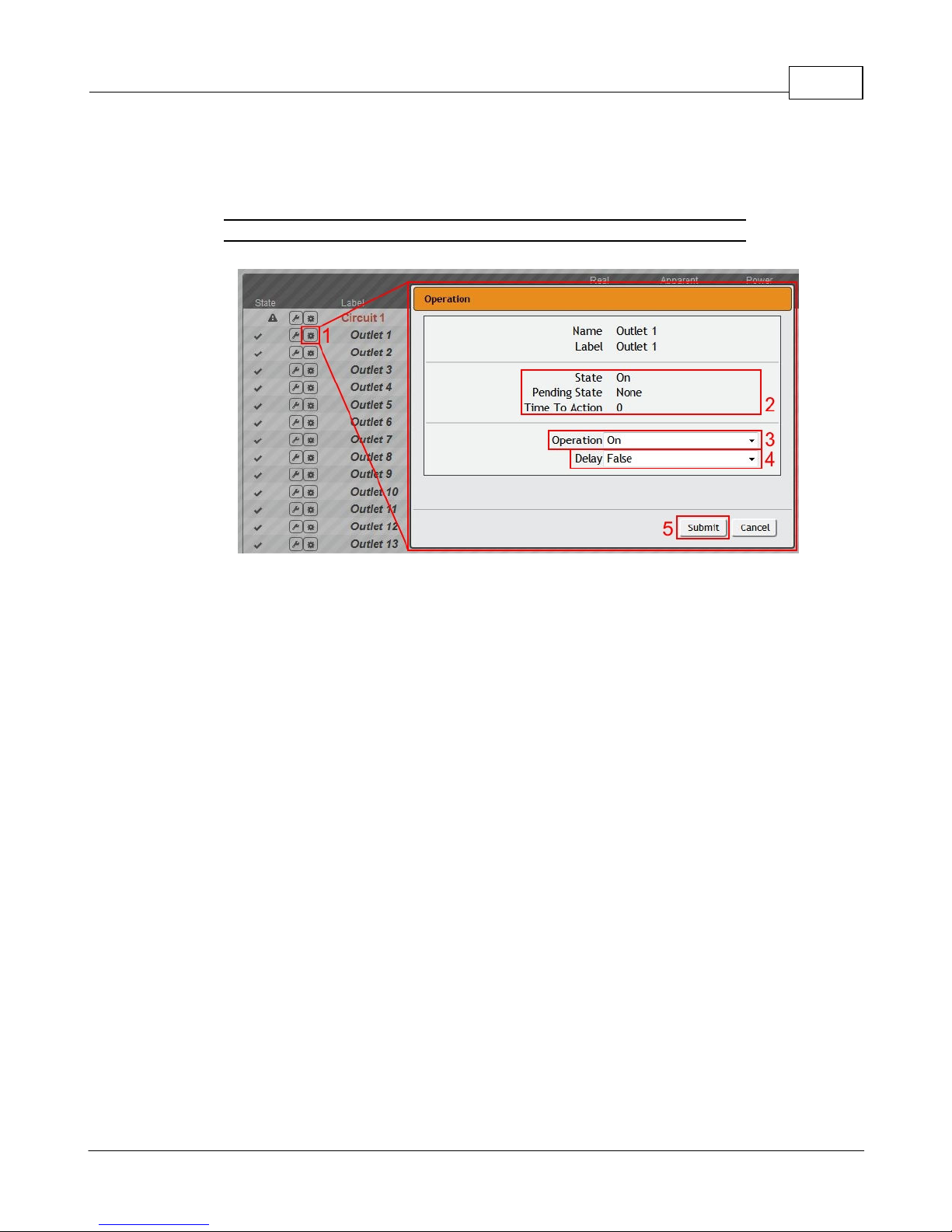
Outlet Operation:
1. Click the desired Outlet Operation icon.
Figure 3-7 Outlet Operation Page
Chapter 3 - Setup 41
2. The outlet's state is described by three descriptors:
· State describes the outlet's current state (On/Off).
· Pending State describes the state the outlet is currently transitioning to, if it is in the
process of switching.
· Time To Action describes the time left before the pending action will take place. This
is adjusted using Delays.
3. Select the operation you wish to perform:
· On/Off turns on/off the selected outlet.
· For an outlet currently on, Reboot cycles the outlet off, then back on after the reboot
hold delay. For an outlet currently off, Reboot turns the outlet on.
· Cancel will cancel the current operation if it has not been completed yet.
· Reset Energy will reset the total Energy measured in kWh for the selected outlet.
· Reset Min Max Values will reset Min and Max values for Voltage and Current
4. For operations involving the state of the outlet, setting Delay to True will use the
current Delay configuration for each outlet when performing the selected operation.
Delays are configured in "Outlet Configuration".
5. Select Submit to issue the action.
GM1196 R-Ser ies v5 Instruction Manual
© 2018 Geist
Page 42
R-Series v5 Instruction Manual42
Alarms & Warnings
The Alarms & Warnings page allows users to establish alarm or warning conditions
(hereafter referred to as "Events") for each power, circuit and outlet readings. Events are
triggered when a measurement exceeds a user-defined threshold, either going above the
threshold ("high-trip") or below it ("low-trip"). Events are displayed in different sections,
based on the device or measurement the Event is associated with. Each Event can have
one or more Actions to be taken when the Event occurs.
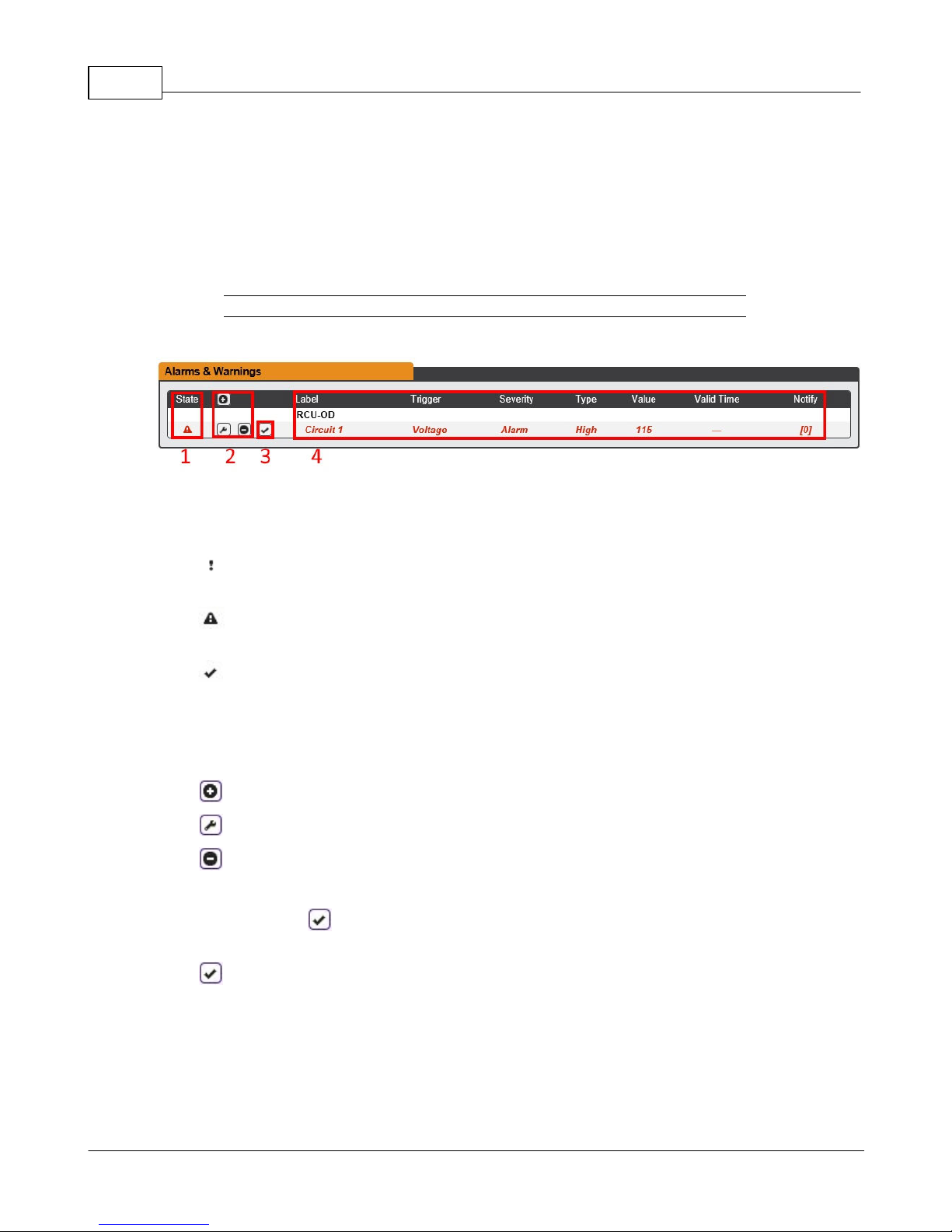
Figure 3-8 Alarms & Warnings Page
1. State: Shows the status of each Event.
· Empty: No alert condition.
· : This symbol indicates that this particular "Warning" Event has been tripped. A
tripped Warning Event displays in orange.
· : This symbol indicates that this particular "Alarm" Event has been tripped. A
tripped Alarm Event displays in red.
· : This symbol will indicate that this Event has not yet been acknowledged by a
user after being tripped. It will remain this way until the condition being measured by
this Event returns to normal (i.e. ceases to exceed the trigger threshold for this
Event.) or the user has clicked the button to acknowledge the Event.
2. Configuration: Add/Delete/Modify Alarms & Warnings.
· : Add new Alarms & Warnings.
· : Modify existing Alarms & Warnings.
· : Delete existing Alarms & Warnings.
3. Notification: Notify user of tripped Events, and request acknowledgment.
· Empty: If the is not present, it means that no alert condition is present or the
Event has been acknowledged.
· : Acknowledge button. When a Warning or Alarm Event has occurred; the user
can click on this symbol to acknowledge the Event and stop the unit from sending
any more notifications about it.
GM1196 R-Ser ies v5 Instruction Manual
© 2018 Geist
Page 43
Chapter 3 - Setup 43
NOTE
Clicking this symbol does not clear the Warning or Alarm Event,
it just stops the notifications from repeating and removes it from
the active Event list.
4. The actual conditions for the various Alarms & Warnings settings are shown here.
Alarms & Warnings Configuration
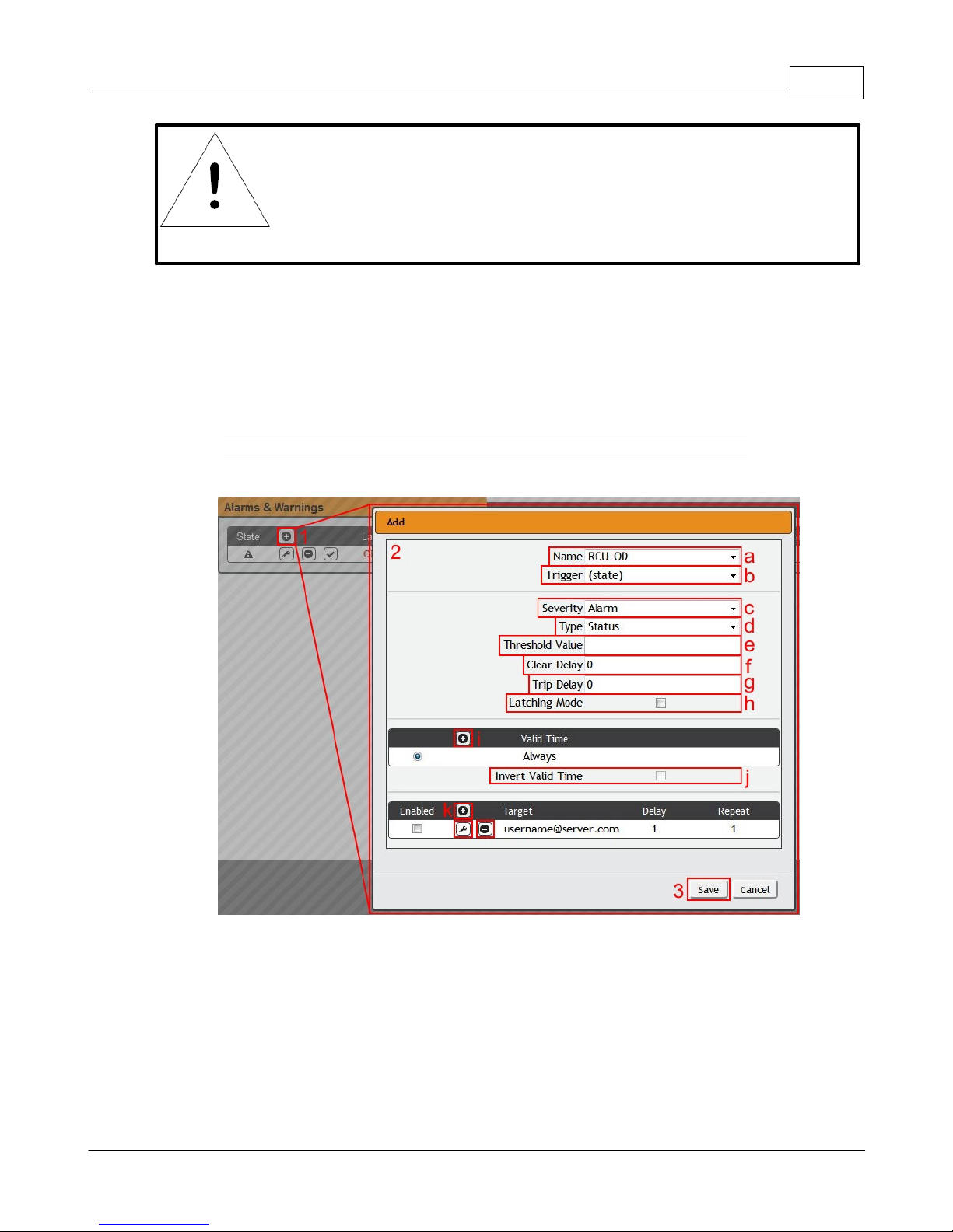
To add a new Alarm or Warning Event:
1. Click the Add/Modify Alarms & Warnings button:
Figure 3-9 Add/Modify Alarms & Warnings Page
2. Set the desired conditions for this Event as follows:
a. Select the Name of the phase or circuit you wish to set an Event on.
b. Select the measurement (current, voltage, etc.) you want to Trigger the Event.
c. Set the Severity level ("Warning", or "Alarm") for this Event.
d. Select the threshold Type, "Status" (trips if device status changes), "high" (trips if
the measurement goes above the threshold) or "low" (trips if the measurement goes
below the threshold).
GM1196 R-Ser ies v5 Instruction Manual
© 2018 Geist
Page 44
R-Series v5 Instruction Manual44
NOTE
Only one valid time can be selected per alarm.
e. Type in the desired Threshold Value (any number between -999.0 ~ 999.0 is valid).
f. Type in the desired Clear Delay time in seconds. Any value other than "0" means
that once this Event is tripped, the measurement must return to normal for this many
seconds before the Event will clear and reset. Clear Delay can be up to 14400
seconds (4 hours).
g. Type in the desired Trip Delay time in seconds. Any value other than "0" means
that the measurement must exceed the threshold for this many seconds before the
Event will be tripped. Trip Delay can be up to 14400 seconds (4 hours).
h. Latching Mode: If enabled, this Event and its associated Actions (see Figure 3-10)
remain active until the Event is acknowledged, even if the measurement
subsequently returns to normal.
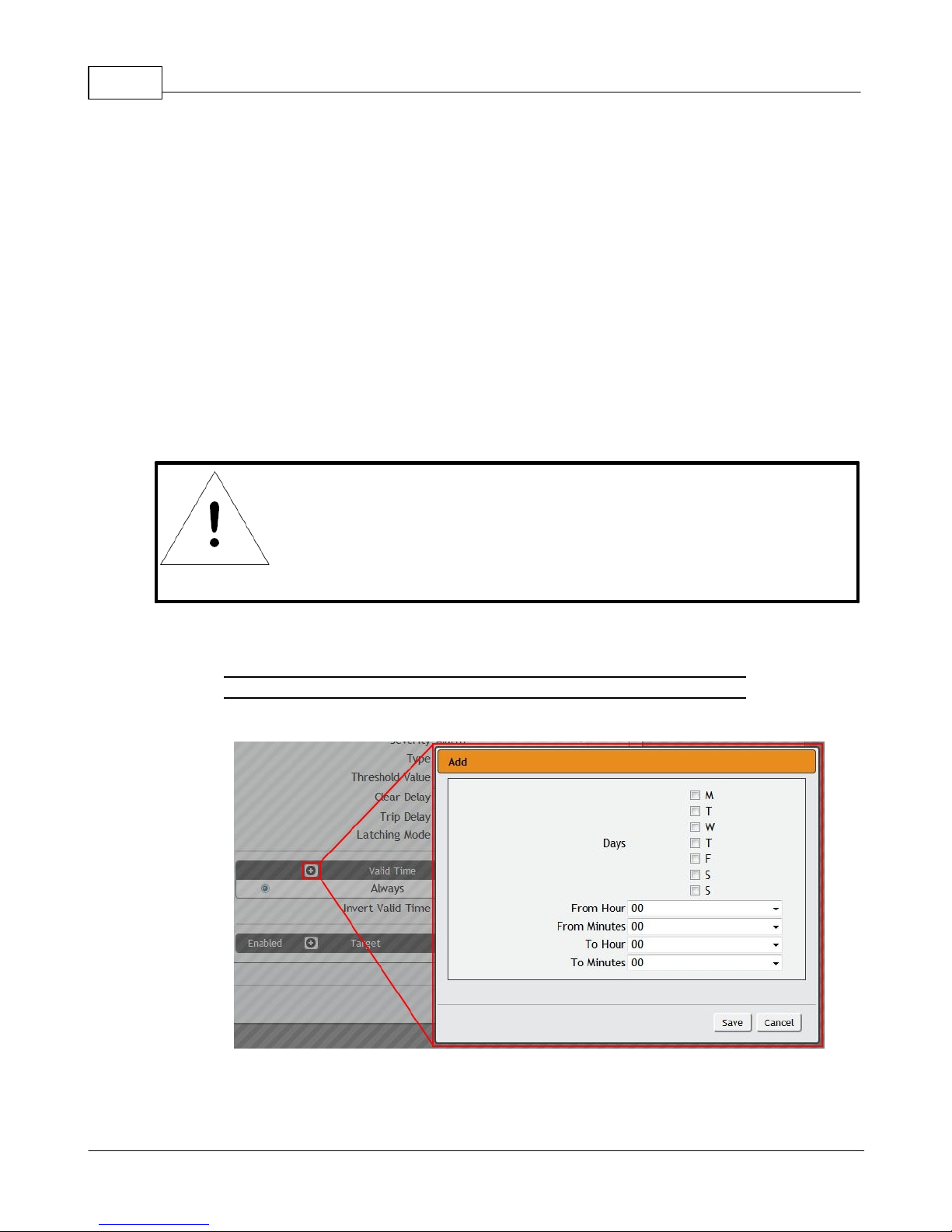
i. Valid Time decides when an Alarm notification can be sent. Valid Time is set by
clicking the Add/Modify icon and setting the days and time ranges notifications will
be sent. Then clicking Save.
Figure 3-10 Add Event Time
j. The Invert Valid Time check box inverts the selected Valid Time setting.
GM1196 R-Ser ies v5 Instruction Manual
© 2018 Geist
Page 45
Chapter 3 - Setup 45
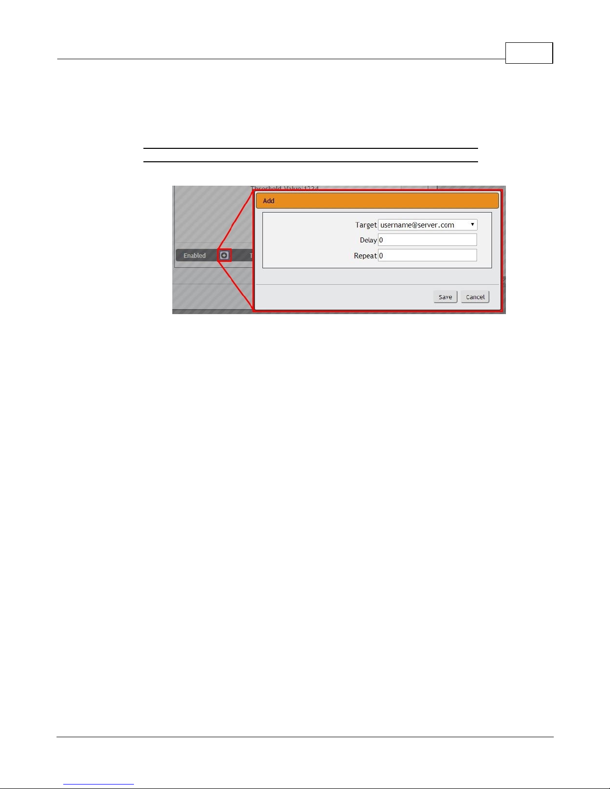
k. To determine where the alert notifications will be sent to when this particular Alarm
or Warning Event occurs, click the Add icon to create a new Action, then select the
desired options from the drop-down menu:
Figure 3-11 Add New Action
· Target is the e-mail address or SNMP manager to which notifications should be
sent when the Event is tripped. Other options, such as "buzzer", may be available
depending on your Geist PDU.
· Delay determines how long this Event must remain tripped before this Action's
first notification is sent. (Note that this is different from the Trip Delay, above; Trip
Delay determines how long the threshold value has to be exceeded before the
Event itself is tripped.) Delay can be up to 14400 seconds (4 hours). A Delay of 0
will send the notification immediately.
· Repeat determines whether multiple notifications will be sent for this Event Action.
Repeat notifications are sent at the specified intervals until the Event is
acknowledged, or until the Event is cleared and reset. The Repeat interval can be
up to 14400 seconds (4 hours). A Repeat of 0 disables this feature, and only one
notification will be sent.
Then, click Save to save this notification Action.
If required, multiple Actions can be set for an Alarm or Warning; to add multiple
Actions click the Add icon again and set each one as desired. Each alert can have
up to 32 Actions associated with it.
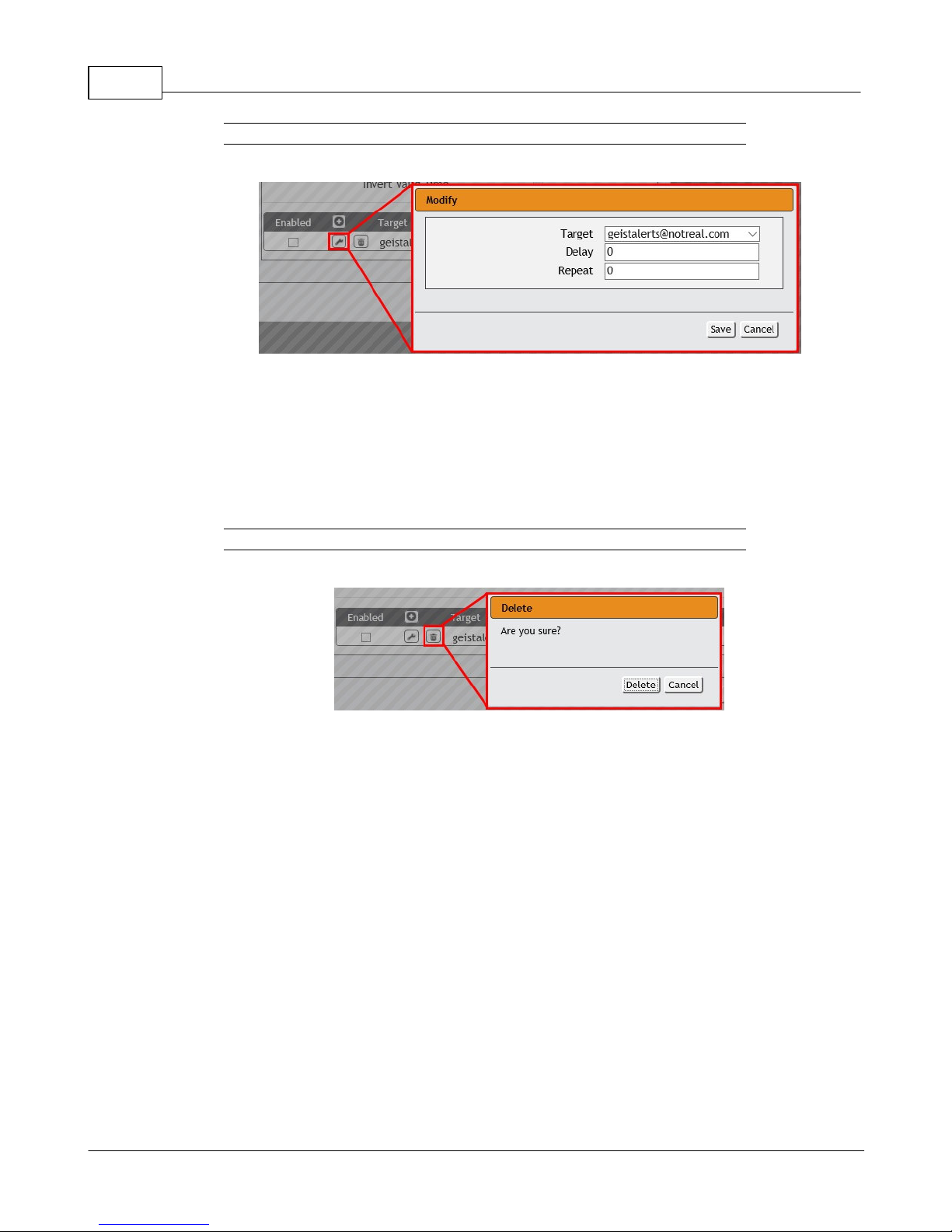
To change an existing notification Action, click the Modify icon next to the Action you
wish to change, then modify its settings as above.
GM1196 R-Ser ies v5 Instruction Manual
© 2018 Geist
Page 46
R-Series v5 Instruction Manual46
Figure 3-12 Modify Action
Once an Action has been added, each Action has its own checkbox in the "enabled"
column at the far left. The default is unchecked (disabled) when you first add each
Action; set the checkbox to enable it. (This allows you to selectively turn different
Actions on and off for testing.)
To remove a notification Action entirely, click the Delete icon to remove the Action
from the list, then click Delete to confirm:
Figure 3-13 Delete Action
3. When finished, click Save to save this Alarm or Warning event.
To change an existing Alarm or Warning Event:
Click the Modify icon next to the Alarm or Warning Event you wish to change, then modify
its settings as above.
To delete an existing Alarm or Warning Event:
Click the Delete icon next to the Alarm or Warning Event you wish to change, then click
Delete to confirm.
Logging
The Logging page allows the user to access the historical data recorded by the PDU
by selecting the desired sensors and time range to be logged.
GM1196 R-Ser ies v5 Instruction Manual
© 2018 Geist
Page 47
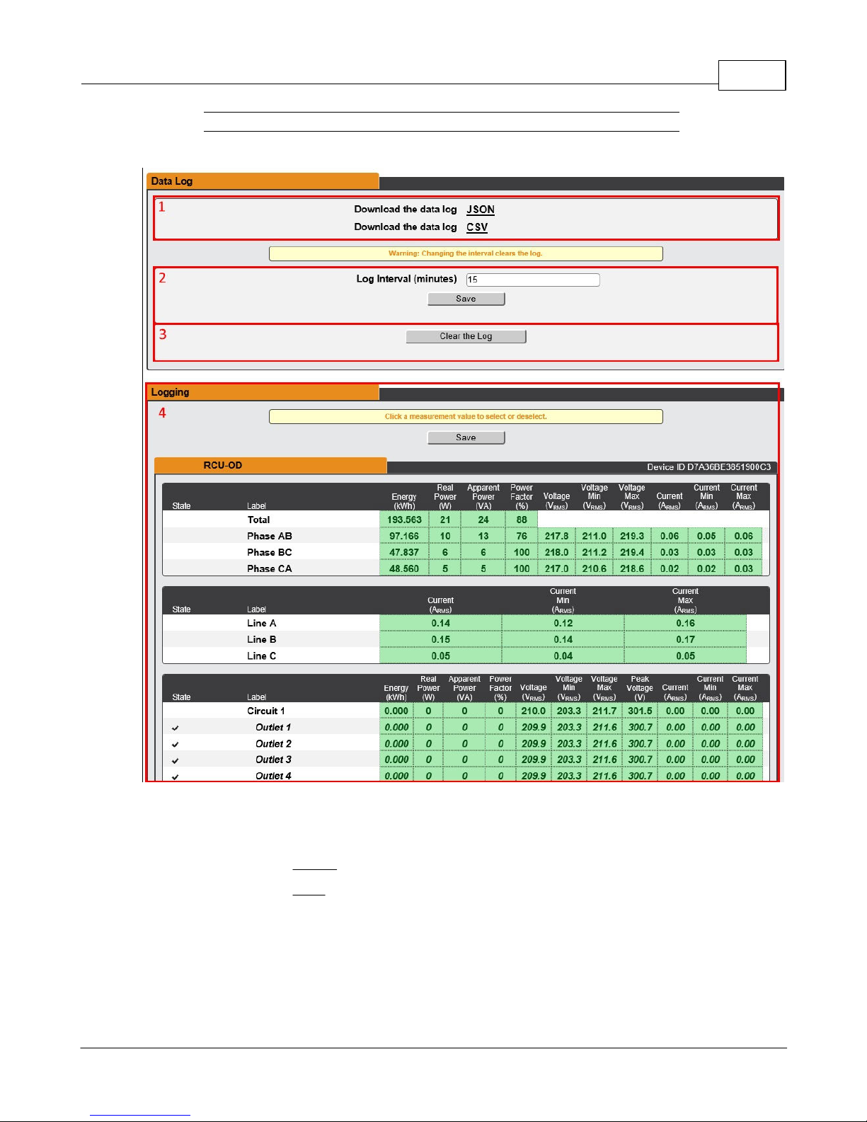
Figure 3-14 Logging Page
Chapter 3 - Setup 47
1. Data Log Download
· Clicking on the JSON link will download the data log in JSON format.
· Clicking on the CSV link will download the data log in .csv format for use in
spreadsheet software such as Microsoft Excel.
GM1196 R-Ser ies v5 Instruction Manual
© 2018 Geist
Page 48
R-Series v5 Instruction Manual48
NOTE
Changing the log interval will result in the data log being cleared.
Please download existing log data prior to changing log
interval.
NOTE
Maximum loggable time frame is determined by number of
measurements being logged and the interval at which data is
written to the log file.
2. Log Interval
· Change the frequency at which data is written to the log file. The logging interval can
be 1-600 minutes with the default setting being 15 minutes.
3. Clear Log Data
· Click on the Clear the Log button to delete log file.
4. Logging
· Click measurement value to select or deselect desired logging parameters. All
measurements are selected by default.
· Press Save button to save changes
System
Users
The Users page in the System menu allows you to manage or restrict access to the unit's
features by creating accounts for different users.
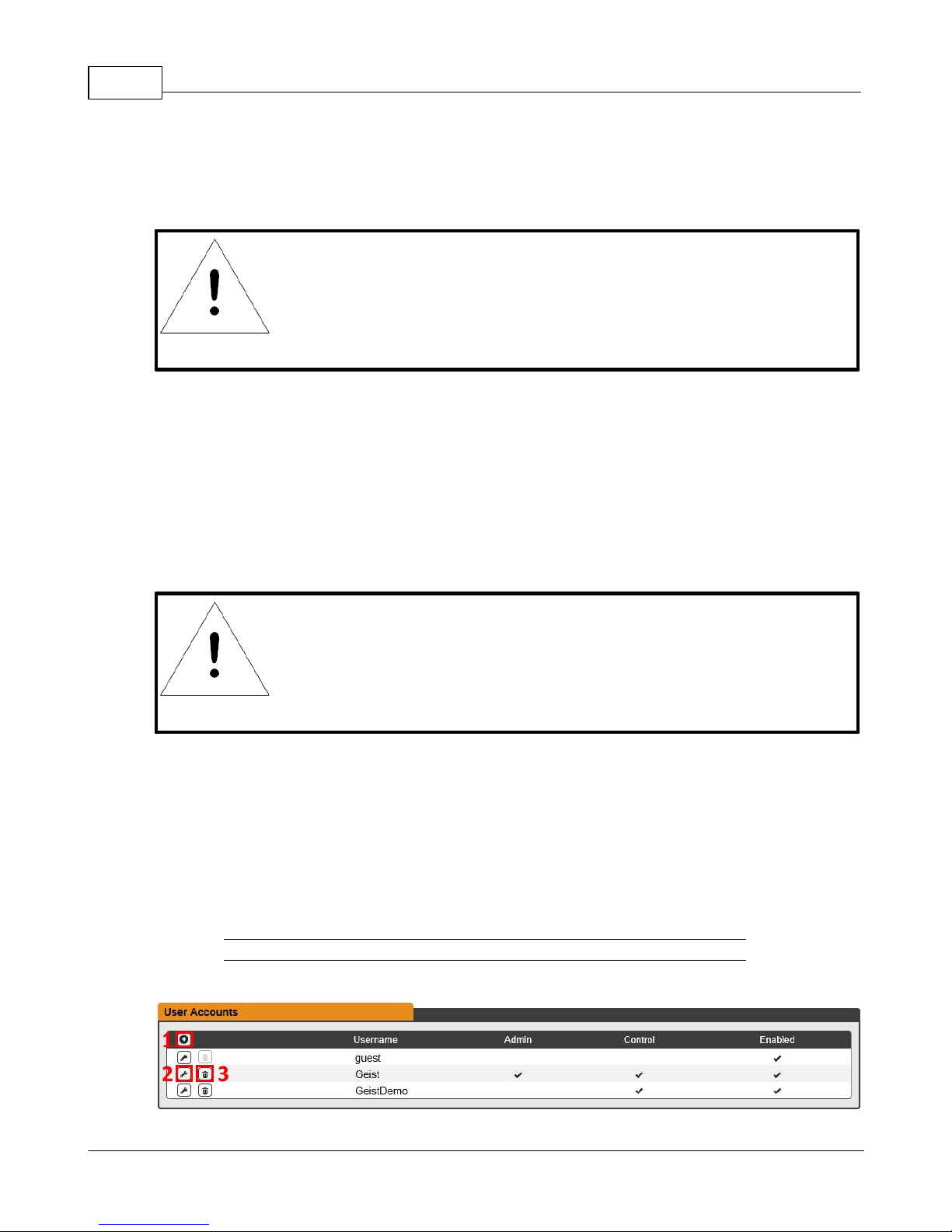
Figure 3-17 User Account Page
GM1196 R-Ser ies v5 Instruction Manual
© 2018 Geist
Page 49
There are three buttons available on the User Accounts page:
NOTE
Only an Administrator-level account can Add, Modify, or Delete
users. Control-level and View-Only accounts can change their
own passwords via the Modify button, but cannot Add or
Delete accounts, or Modify other accounts. The Guest account
cannot Add, Delete, or Modify any account, not even itself.
1. Add New User Account
2. Modify User's Account
3. Delete User's Account
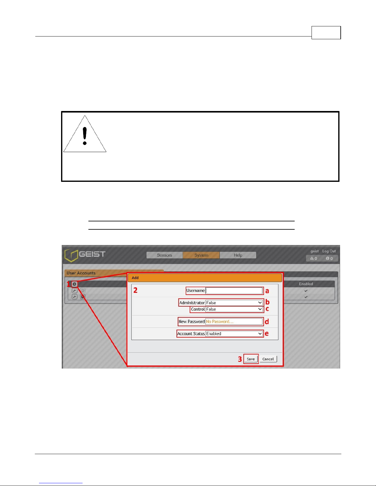
To Add a user Account:
1. Click the Add User icon.
Chapter 3 - Setup 49
Figure 3-18 Add User Account Page
2. Create the account information as follows:
a. Username: the name of this account. User names may be up to 24 characters
long, are case-sensitive, and may not contain spaces or any of these prohibited
characters: $&`:<>[ ] { }"+%@/ ; =?\^|~', Note that an account's username cannot be
changed after the account is created.
b. Administrator: if set to True, this account has Administrator-level access to the
unit, and can change any setting.
GM1196 R-Ser ies v5 Instruction Manual
© 2018 Geist
Page 50
R-Series v5 Instruction Manual50
NOTE
Strong passwords typically contain at least 8 characters with a
mix of Alpha (lower and upper case), numeric, and special
characters.
c. Control: if set to True, this account has Control-level access. Setting Administrator
to True will automatically set Control to True as well. Setting this to False makes the
account a View-Only account.
d. New Password: account passwords may be up to 24 characters long, are case-
sensitive, and may not contain spaces.
e. Account Status: set the account to Enabled or Disabled. Disabling an account
prevents it from being used to log in, but does not delete it from the account list.
3. Click the Save button when finished.
Account Types:
· Administrator: Administrator accounts (accounts with both Administrator and
Control authority set to True, as above) have full control over all available functions
and settings on the device, including the ability to modify System settings and add,
modify, or delete other users' accounts.
· Control: Control accounts (accounts with only Control set to True) have control over
all settings pertaining to the device's sensors. They can add, modify, or delete
Alarms & Warning Events and notification Actions, and can change the names or
labels of the device and its sensors. Control accounts cannot, however, modify
System settings or make changes to other users' accounts.
· View: If both Administrator and Control are set to False, the account is a View-Only
account. The only changes a View-Only account is permitted to make are changing
their own account's password, and changing the preferred language for their own
account. View-Only accounts cannot change any device or system settings.
· Guest: Anyone who brings up the unit's web page without logging in will
automatically be viewing the unit as Guest. By default, the Guest account is a ViewOnly account, and cannot make changes to any settings, although the Administrator
can elevate the Guest account to Control-level access if desired, allowing anyone to
make changes to names, labels, alarm events, and notifications without logging in.
The Guest account cannot be deleted but can be disabled to require login for viewing
system status.
GM1196 R-Ser ies v5 Instruction Manual
© 2018 Geist
Page 51
NOTE
Once a user has logged in to their account, they can change their
password or language preference by clicking their username,
shown next to the Log Out hyperlink at the top right-hand corner
of the web page.
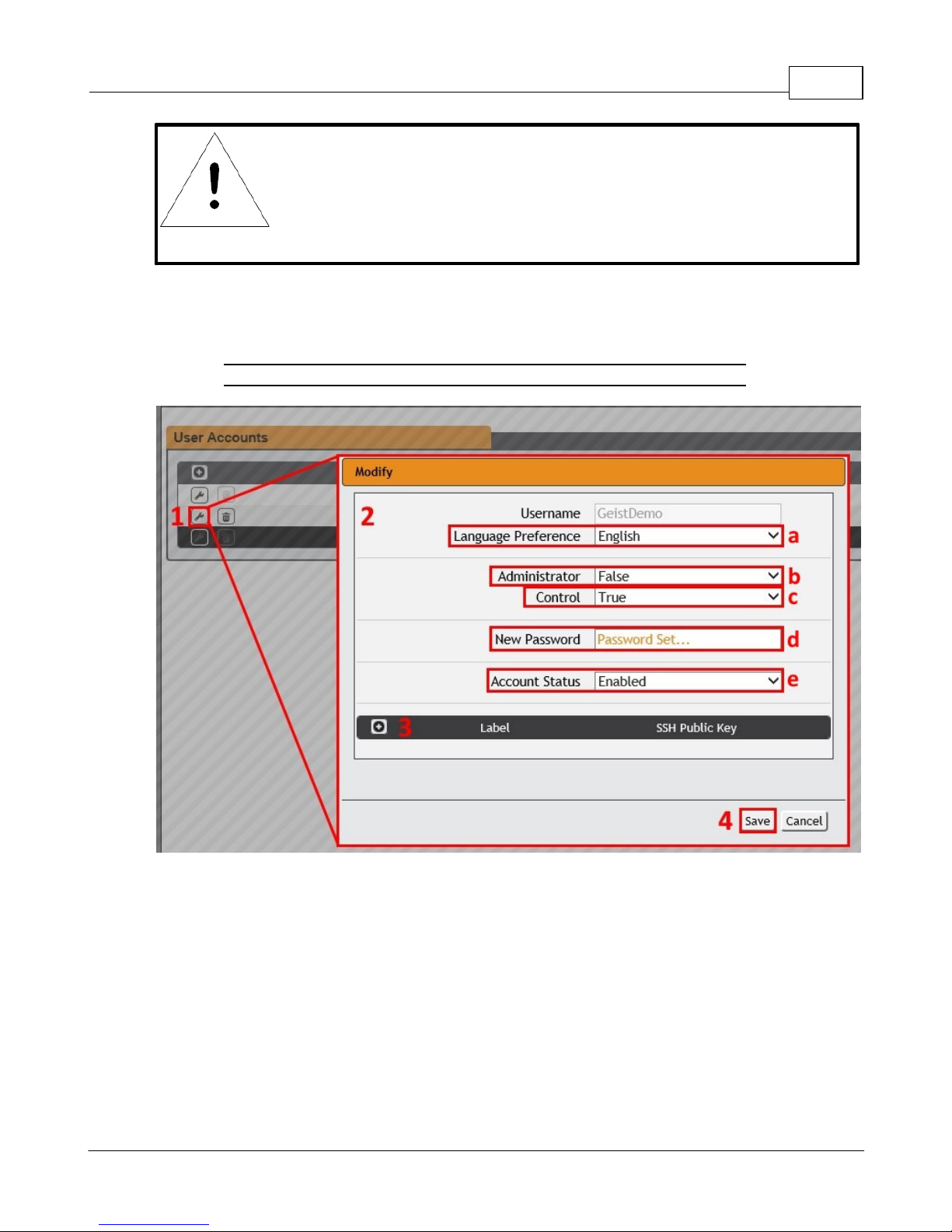
To Modify a user Account:
1. Click the Modify User icon.
Figure 3-19 Modify User Page
Chapter 3 - Setup 51
2. Modify the account information as follows:
a. Language preference: Change the default language for this user. Options are
English, French, Spanish, German, Portuguese, Japanese, Chinese and Korean.
b. Administrator: if set to True, this account has Administrator-level access to the
unit, and can change any setting. This option can only be modified by an
Administrator level account.
c. Control: if set to True, this account has Control-level access. Setting Administrator
to True will automatically set Control to True as well. Setting this to False makes the
account a View-Only account. This option can only be modified by an Administrator
level account.
GM1196 R-Ser ies v5 Instruction Manual
© 2018 Geist
Page 52
R-Series v5 Instruction Manual52
NOTE
Strong passwords typically contain at least 8 characters with a
mix of Alpha (lower and upper case), numeric, and special
characters.
d. New Password: account passwords may be up to 24 characters long, are case-
sensitive, and may not contain spaces.
e. Account Status: set the account to Enabled or Disabled. Disabling an account
prevents it from being used to log in, but does not delete it from the account list.
This option can only be modified by an Administrator level account.
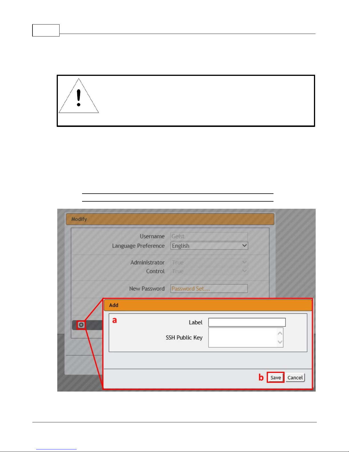
3. Click the add icon to add a user specific SSH Public Key
a. Enter Label and SSH Public Key information
b. Click Save button when finished.
Figure 3-20 Add Icon
4. Click the Save button when finished.
GM1196 R-Ser ies v5 Instruction Manual
© 2018 Geist
Page 53
Chapter 3 - Setup 53
Network
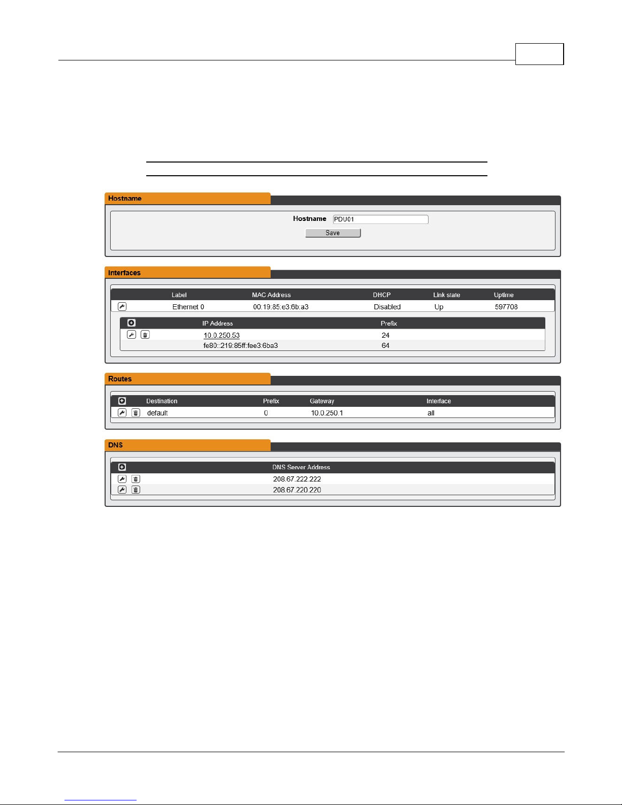
The unit’s network configuration is set on the Network tab of the System menu. Settings
pertaining to the unit’s network connection are:
Figure 3-21 Network Configuration Page
· Hostname: The Hostname may be used as a method for device identification on the
network.
GM1196 R-Ser ies v5 Instruction Manual
© 2018 Geist
Page 54
R-Series v5 Instruction Manual54
· Interfaces: This section is used to configure the IP address of the PDU, enable/disable
DHCP and to view Link State and Uptime. The device will support up to 8 user
configured IP address entries.
· Routes: Displays configured routes and is where you will set your Gateway address for
the PDU. Default routes are distinguished by a "destination" of "0.0.0.0" or "::", with a
Prefix of "0" and Interface of "all". Only one default route can exist for IPv4 and one for
IPv6.
· DNS: Allows the unit to resolve host names for email, NTP, and SNMP servers.
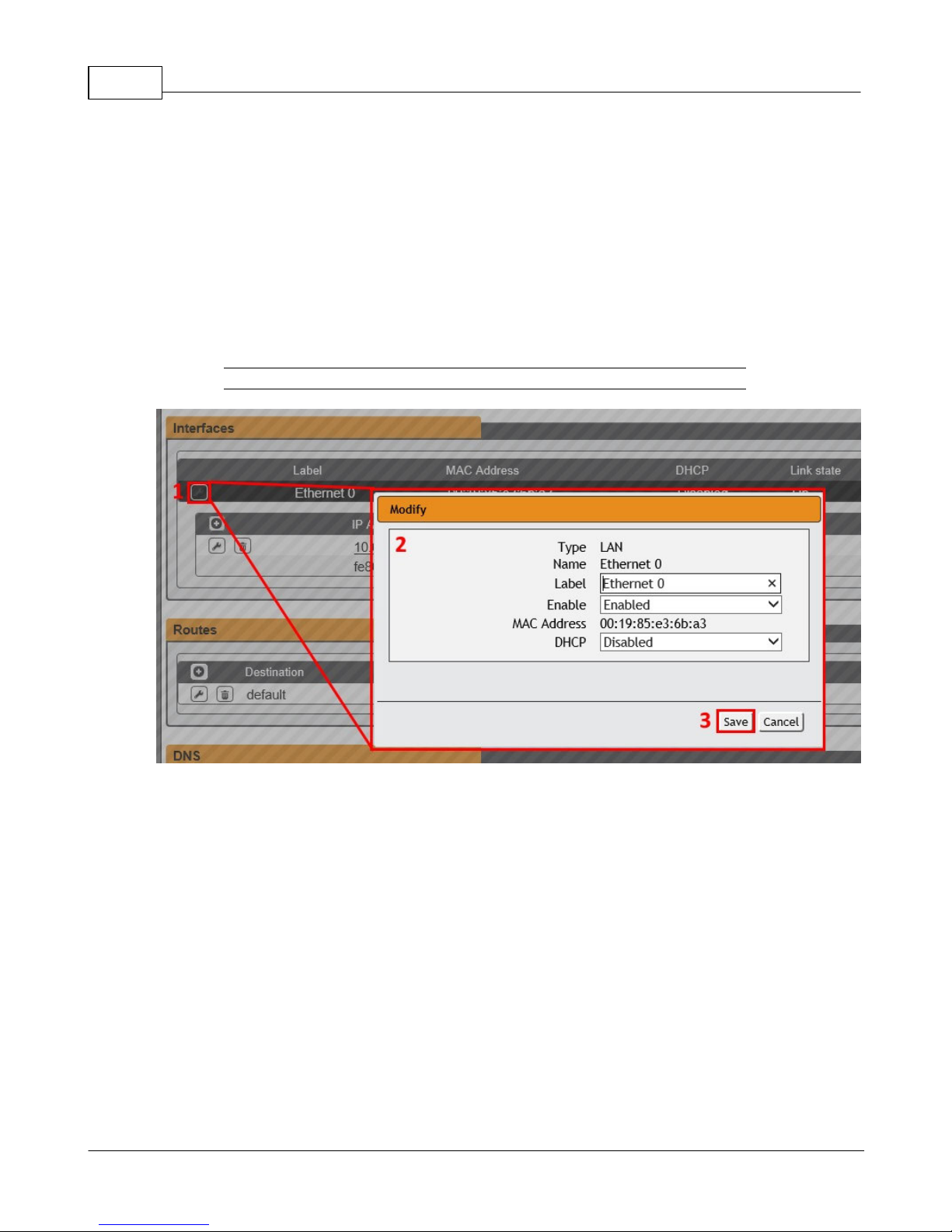
Figure 3-22 Editing Interfaces Parameters
To edit the Interfaces parameters:
1. Click the Modify icon
2. Modify desired fields which include:
a. Label - Change the desired name of the selected interface.
b. Enable - Enable/Disable the selected interface. Please note that if only one
interface is available/configured, disabling the interface will restrict
access to the device requiring a network reset.
c. DHCP - Enable/Disable DHCP on the selected interface. DHCP is enabled by
default and will be disabled if a static IP address is configured.
3. Click the Save button
GM1196 R-Ser ies v5 Instruction Manual
© 2018 Geist
Page 55
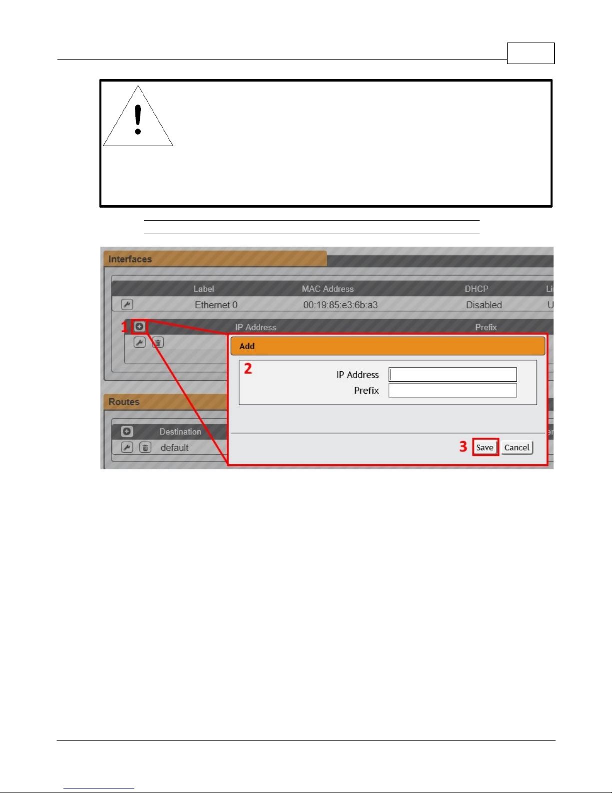
NOTE
Any changes you make to the Network Interface settings will
take effect once the Save button is clicked! If you have
changed the IP address it will appear as if the unit is no longer
responding because the browser will not be able to reload the
web page. Just stop or close the browser window, then type
the new IP address into the browser's address bar, and the unit
will be accessible.
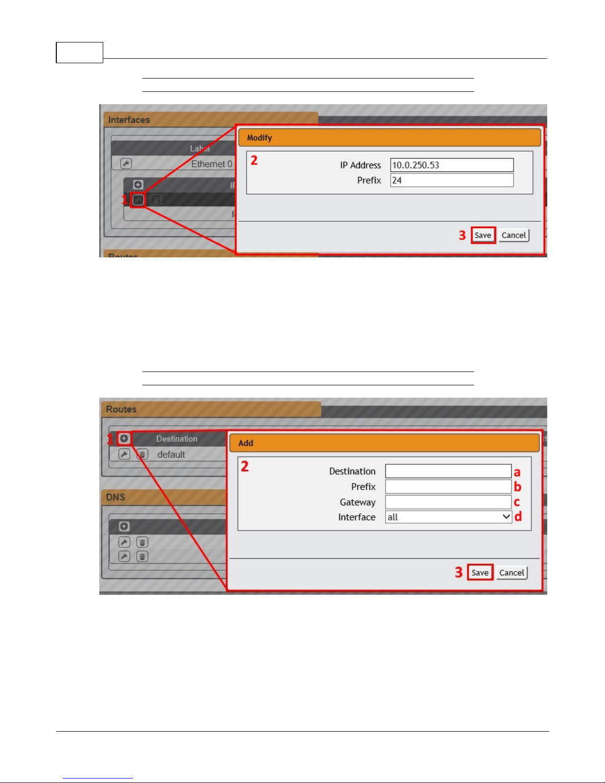
Figure 3-23 Add New IP Address
Chapter 3 - Setup 55
To add a new IP Address:
1. Click the Add icon.
2. Enter the IPv4 or IPv6 Address and Prefix/Subnet Mask into appropriate fields. Up to 8
IP addresses can be statically assigned.
3. Click the Save button.
GM1196 R-Ser ies v5 Instruction Manual
© 2018 Geist
Page 56
R-Series v5 Instruction Manual56
Figure 3-24 Modify Existing IP Address
To modify an existing IP Address:
1. Click the Modify icon.
2. Edit the IP Address and Prefix/Subnet Mask fields as needed.
3. Click the Save button.
To add a new Route:
1. Click the Add icon.
Figure 3-25 Add a New Route
2. Enter the appropriate information
a. Destination IP address for desired route
b. Enter Prefix for desired route
GM1196 R-Ser ies v5 Instruction Manual
© 2018 Geist
Page 57
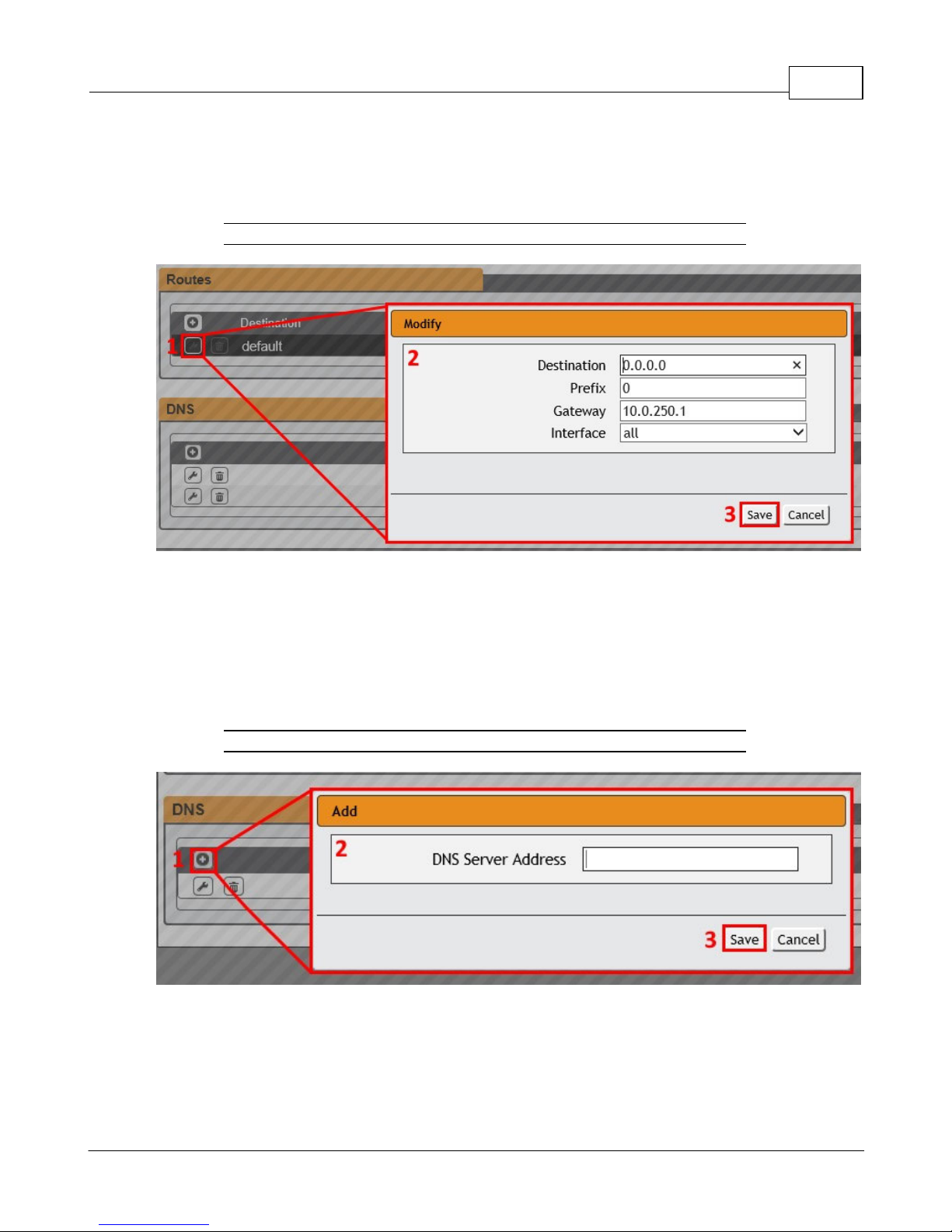
c. Enter Gateway IP address
d. Select Interface that route applies to
3. Click the Save button.
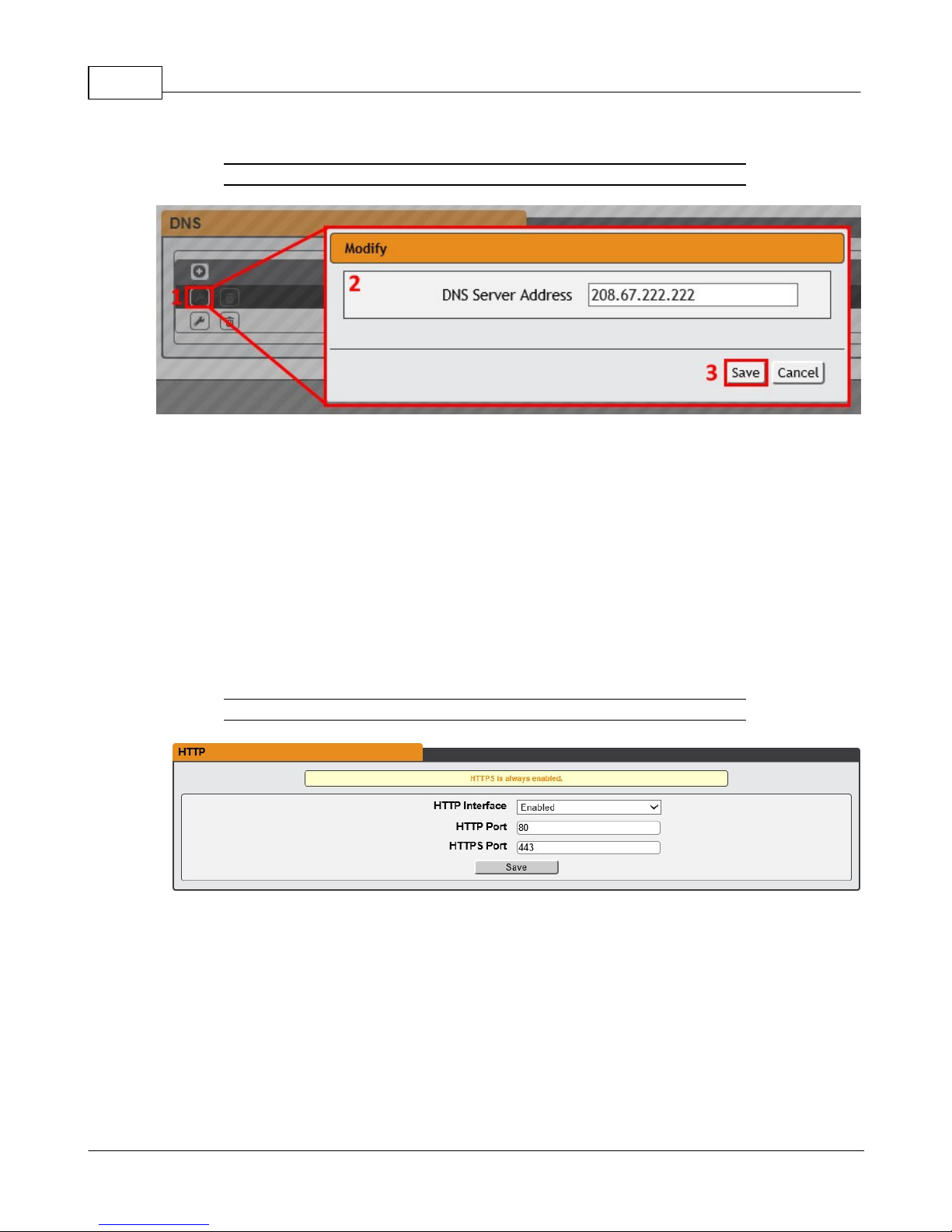
Figure 3-26 Modify an Existing Route
Chapter 3 - Setup 57
To modify an existing Route:
1. Click the Modify icon
2. Edit the desired fields
3. Click the Save button
Figure 3-27 Add a New DNS Server Address
To add a new DNS Server Address:
1. Click the Add icon.
2. Enter the IP of the desired DNS server. Up to two DNS servers can be added.
GM1196 R-Ser ies v5 Instruction Manual
© 2018 Geist
Page 58
R-Series v5 Instruction Manual58
3. Click the Save button.
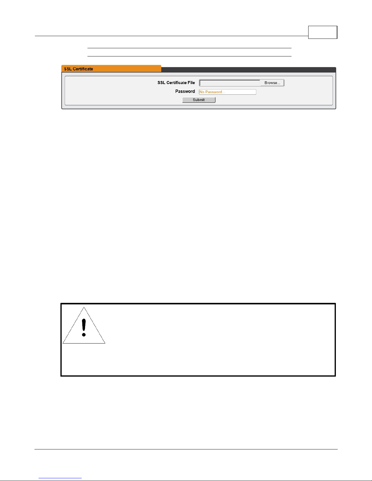
Figure 3-28 Modify an Existing DNS Server IP Address
To modify an existing DNS Server Address:
1. Click the Modify icon
2. Edit the DNS Server Address field as required
3. Click the Save button
Web Server
The unit’s Web Server configuration page can be used to update Web Server information
and upload self-signed SSL certificates.
Figure 3-29 Web Server Configuration Page
· HTTP Interface: Enables/disables access via HTTP. HTTPS interface will always be
enabled. Available options are: Enabled or Disabled. It is not possible to disable the
web interface completely.
· HTTP/HTTPS Server Port: Allows you to change the TCP ports which the HTTP and
HTTPS services listen to for incoming connections. The defaults are port 80 for HTTP
and 443 for HTTPS.
GM1196 R-Ser ies v5 Instruction Manual
© 2018 Geist
Page 59
Chapter 3 - Setup 59
NOTE
If the certificate is password protected, you will need to enter
that password into the GUI to upload the certificate successfully.
Figure 3-30 SSL Certificate Configuration Page
· SSL Certificate: Allows you to upload your own signed SSL Certificate file to replace
the default one. The certificate can be either self-signed or signed from a Certification
Authority. Certificate must meet the following parameters:
Certificate must be in either PEM or PFX (PKCS12) format
· PEM Format
1. The public certificate and private key must reside in the same file
2. The certificate must follow standard x.509
3. The private key must be generated with the RSA algorithm and in PEM format
4. The PEM RSA private key may be password secured.
· PFX Format
Support is also available for the PKCS12 standard (.pfx) which is a binary
encrypted combination of a PEM public certificate and its PEM private key.
When generating a PFX certificate you will be prompted for an optional
password.
GM1196 R-Ser ies v5 Instruction Manual
© 2018 Geist
Page 60
R-Series v5 Instruction Manual60
NOTE
SMTP email must be set-up on the device via the Email page.
Reports
The Reports page allows the user to schedule the device to send recurring status reports.
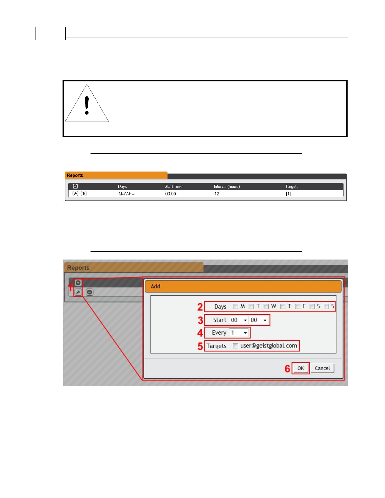
Figure 3-31 Reports Page
To Add or Modify a scheduled report:
1. Click the Add or Modify icon.
Figure 3-32 Add or Modify Report Schedule
2. Select the Days the report is to be sent.
3. Select the time of the day to Start sending reports.
4. Set the interval (in hours).
GM1196 R-Ser ies v5 Instruction Manual
© 2018 Geist
Page 61
Chapter 3 - Setup 61
5. Select the Target email address for the reports to be sent.
6. Click OK to save changes.
To Delete a scheduled Report:
1. Click on the Delete icon next to the report to delete.
2. Click the OK button on the pop-up window to confirm.
LDAP
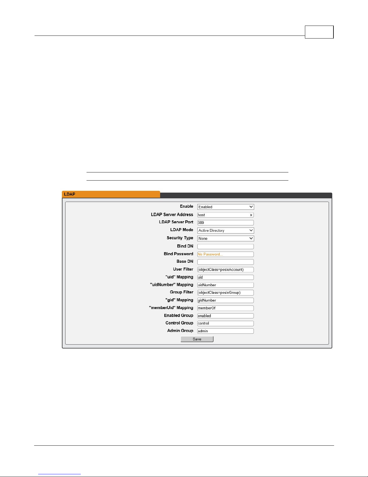
The Lightweight Directory Access Protocol (LDAP) can be setup through this menu.
Figure 3-33 LDAP Menu
· Enable: Enabling or Disabling LDAP.
· LDAP Server Address: Specify the host address for LDAP. The "HOST" can be an
IPv4 address, an IPv6 address in brackets (ie. [2001:0DB8:AC10:FE01::]), or a host
name.
· LDAP Server Port: Used to set the LDAP port number. The default port for LDAP is
389.
GM1196 R-Ser ies v5 Instruction Manual
© 2018 Geist
Page 62

R-Series v5 Instruction Manual62
· LDAP Mode: Available LDAP modes are Active Directory or OpenLDAP.
· Bind Password: Password used to bind to the directory server.
· Base DN: DN to use for the search base.
The remaining fields come from the NIS schema, defined in RFC2307. They are used to
authenticate users in LDAP. Leaving them blank will use the default value, which is shown
in the picture, in orange.
· User Filter: LDAP filter for selecting users.
· "uid" Mapping: Name of the server attribute that corresponds to the "uid" attribute in
the schema.
· "uidNumber" Mapping: Name of the server attribute that corresponds to the
"uidNumber" attribute in the schema.
· Group Filter: LDAP filter for selecting groups.
· "gid" Mapping: Name of the server attribute that corresponds to the "gid" attribute in
the schema.
· "memberUid" Mapping: Name of the server attribute that corresponds to the
"memberUid" attribute in the schema.
· Enabled Group: Users in this group will have access to unit and permissions based on
Control Group and Admin Group settings.
· Control Group: Users in this group have "control" privileges as described in the
Users
section of this manual.
· Admin Group: Users in this group have "admin" privileges as described in the
Users
section of this manual. LDAP users do not count toward minimum number of required
admin users.
GM1196 R-Ser ies v5 Instruction Manual
© 2018 Geist
Page 63
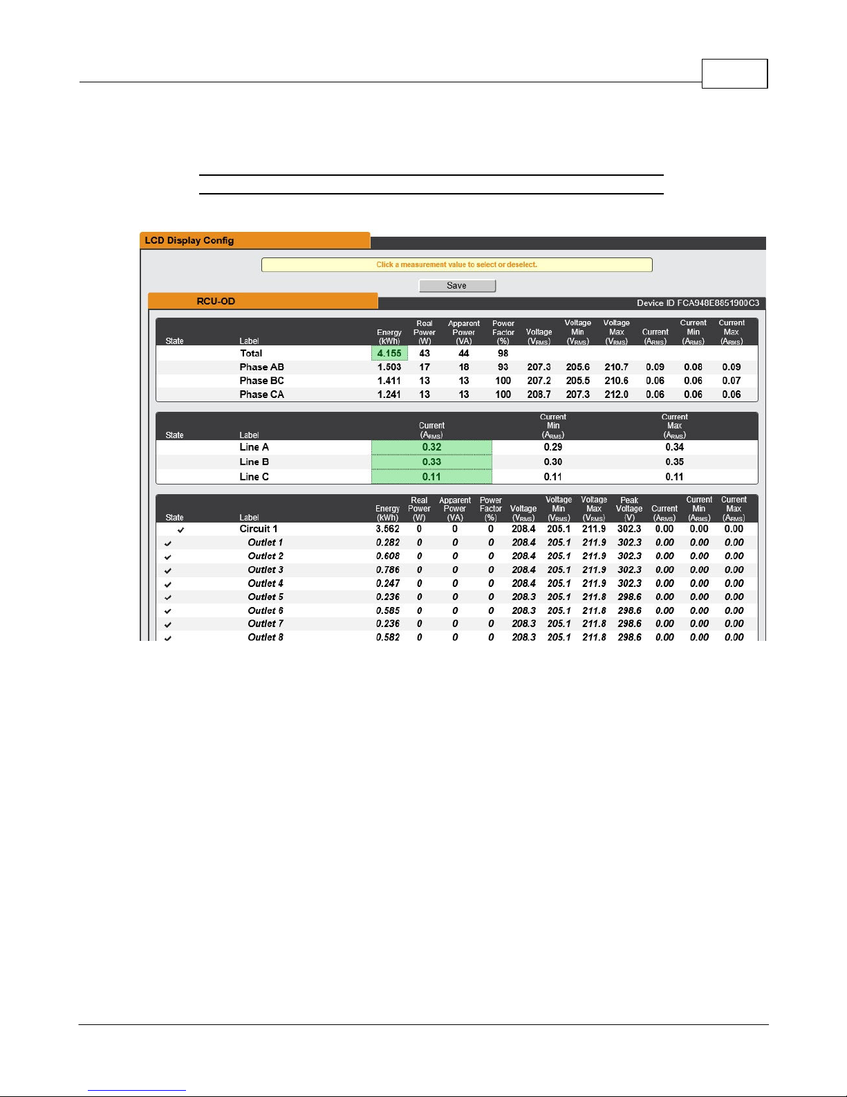
Chapter 3 - Setup 63
Display
The unit's display configuration can be changed via the Display tab of the System menu.
Figure 3-34 Display Page
The Display page allows the user to configure what measurements are scrolling on the
local or remote LCD display.
To Add measurements:
1. Click the value that is desired. A highlighted value will indicate that the value will be
shown on the local LCD display.
2. Click the Save button.
To Remove measurements:
3. Click the highlighted value that is desired to deselect it from the display.
4. Click the Save button.
GM1196 R-Ser ies v5 Instruction Manual
© 2018 Geist
Page 64
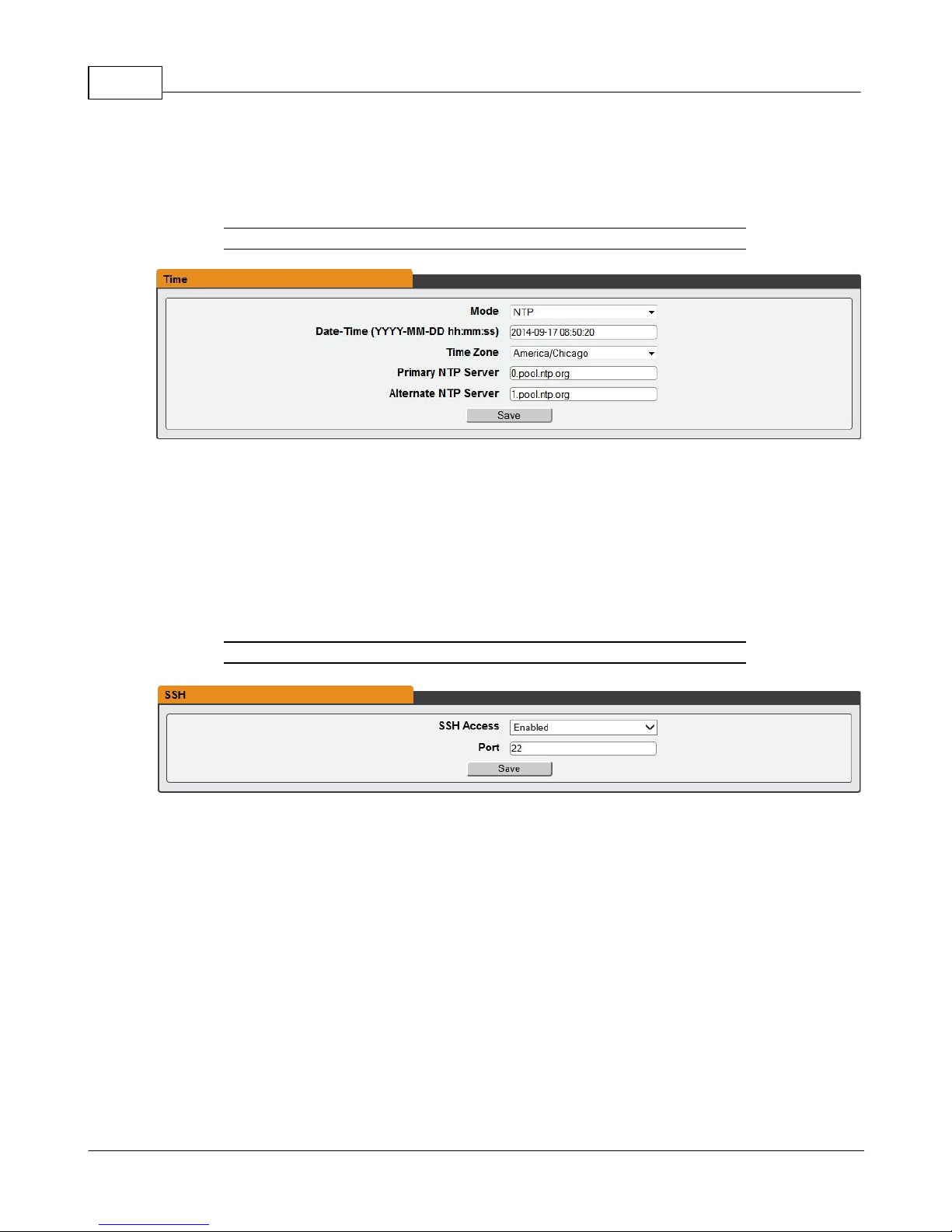
R-Series v5 Instruction Manual64
Time
The unit's time and date are set on this page.
Figure 3-35 Time Configuration Page
There are two mode available: Network Time Protocol (NTP) and Manual.
1. NTP synchronizes the unit's time and date to the specified time zone using listed NTP
Servers. NTP servers can be reconfigured.
2. In Manual mode, the date and time must be typed as indicated on the left of the field.
SSH
The SSH menu allows you to configure settings for SSH access to the device.
Figure 3-36 SSH Configuration Page
· SSH Access: Enables/disables access via SSH.
· SSH Port: Allows you to change the port which the SSH service listen to for incoming
connections. The default is port 22.
Email
The unit is capable of sending email notifications to up to ten email addresses when an
Alarm or Warning Event occurs.
GM1196 R-Ser ies v5 Instruction Manual
© 2018 Geist
Page 65
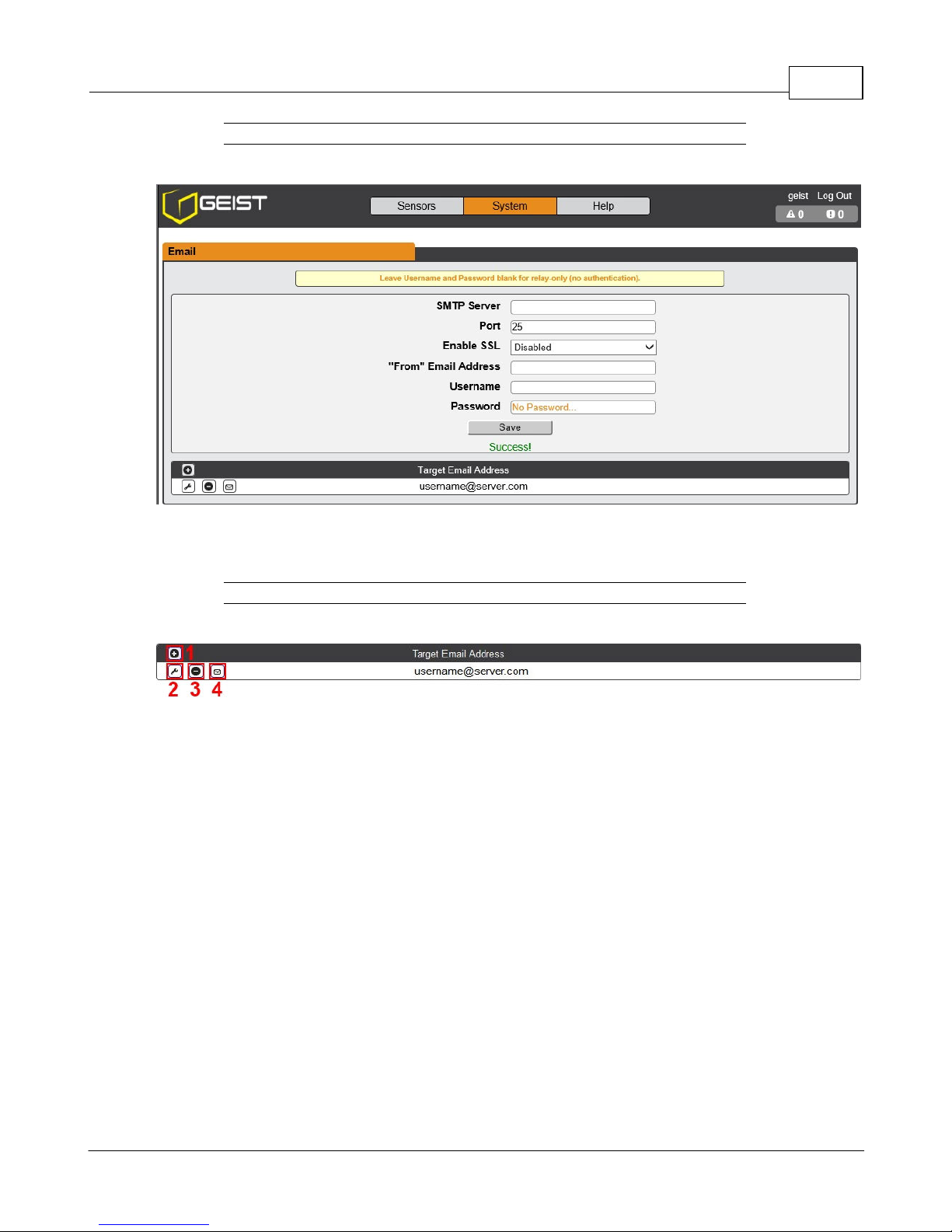
Figure 3-37 Email Configuration Page
Chapter 3 - Setup 65
Target email addresses can be configured as follows:
Figure 3-38 Email Target Address Page
Legend of icons/buttons:
1. Add new target email address.
2. Modify existing target email address.
3. Delete existing target email address.
4. Send test email.
To send emails, the unit must be configured to access the mail server, as follows:
· SMTP Server: The name or IP address of a suitable SMTP or ESMTP server.
· Port: The TCP port which the SMTP Server uses to provide mail services. Typical
values would be port 25 for an unencrypted connection, or 465 and 587 for a TLS/SSLencrypted connection, but these may vary depending on the mail server's configuration.
· Enable SSL: If Enabled, the unit will attempt to connect to the server using a fully-
encrypted TLS/SSL connection. When this setting is enabled only fully-encrypted
GM1196 R-Ser ies v5 Instruction Manual
© 2018 Geist
Page 66
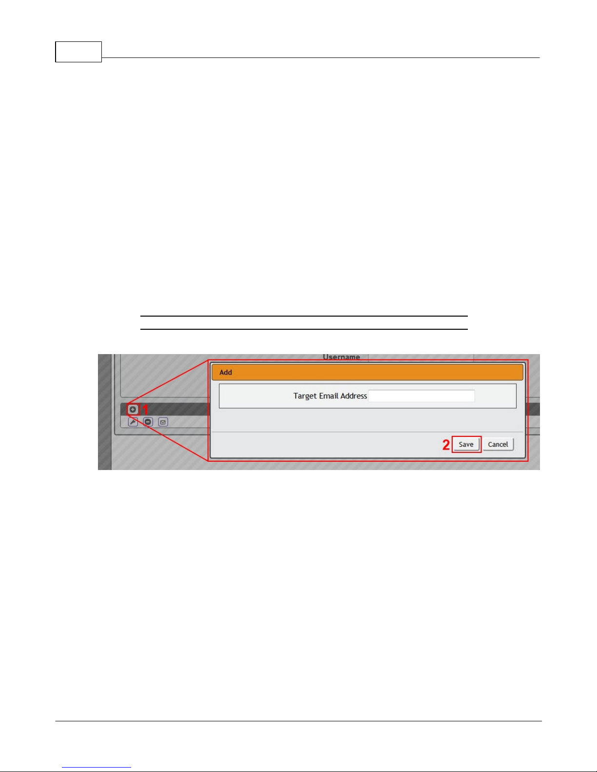
R-Series v5 Instruction Manual66
sessions are supported; the "StartTLS" method, where the session starts out as
unencrypted and then switches to encrypted partway through the session, is not
supported. If using a service that utilizes StartTLS, such as Office365, please leave this
option Disabled.
· "From" Email Address: The address which the unit's emails should appear to come
from. Many hosted email services, such as Gmail, will require this to be the email
account of a valid user.
· Username and Password: The login credentials for the email server. If your server
does not require authentication (open relay), these can be left blank.
Microsoft Exchange servers will have to be set to allow SMTP relay from the IP address of
the unit. In addition, the Exchange server will need to be set to allow "Basic
Authentication", so that the unit will be able to log in with the AUTH LOGIN method of
sending its login credentials. Other methods, such as AUTH PLAIN, AUTH MD5, etc. are
not supported.
Figure 3-39 Email Target Configuration Page
To Add or Modify a Target Email address:
1. Click on the Add or Modify icon.
2. Type email address and then click Save.
To Delete a Target Email address:
1. Click on the Delete icon next to the address you wish to delete.
2. Click the Delete button on the pop-up window to confirm.
To send a test email:
1. Click on the Test Email icon next to the address you wish to test.
2. A pop-up window will indicate that the test email is being sent. Click OK to dismiss
the pop-up.
SNMP
Simple Network Management Protocol (SNMP) can be used to monitor the unit's
measurements and status, if desired. SNMP v1, v2c and v3 are supported. In addition,
GM1196 R-Ser ies v5 Instruction Manual
© 2018 Geist
Page 67
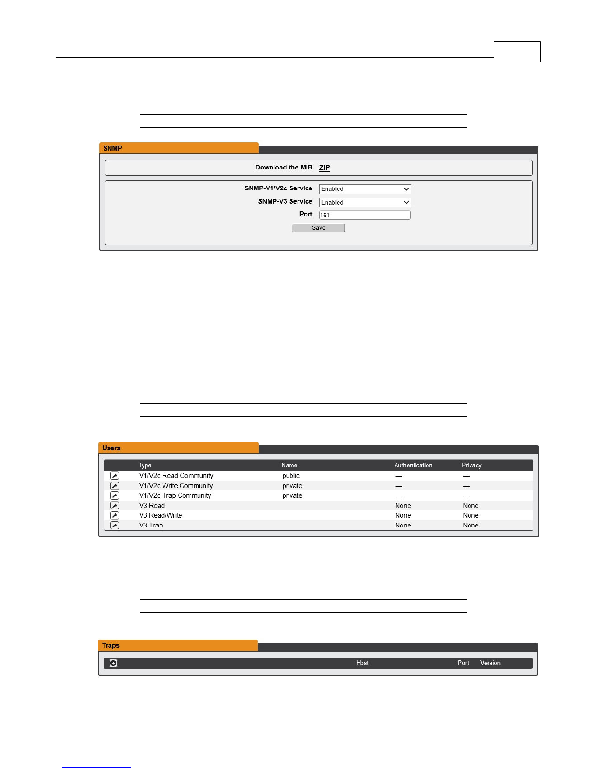
Chapter 3 - Setup 67
alarm traps can be sent to up to two IP addresses.
Figure 3-40 SNMP Configuration Page
The SNMP-V1/V2c and SNMP-V3 Service can be enabled or disabled independently as
desired. The service will normally listen for data-read requests (a.k.a. "GET requests") on
Port 161, which is the usual default for SNMP services; this can also be changed if
desired.
The Management Information Base (MIB) can be downloaded from the unit, if needed, via
the MIB link at the top of the web page. Clicking this link will download a .ZIP archive
containing both the MIB file itself, and a CSV-formatted spreadsheet describing the
available OIDs in a human-readable form to assist you in setting up your SNMP manager
to read data from the unit.
Figure 3-41 SNMP Users Configuration Page
The Users section allows you to configure the various Read, Write, and Trap communities
for SNMP services. You can also configure the authentication types and encryption
methods used for the SNMP v3 if desired. Click the Modify icon to change settings.
Figure 3-42 SNMP Traps Configuration Page
GM1196 R-Ser ies v5 Instruction Manual
© 2018 Geist
Page 68
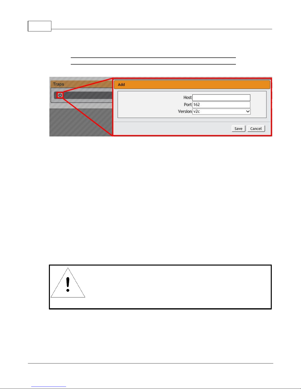
R-Series v5 Instruction Manual68
NOTE
This function is primarily only useful for diagnostic purposes,
and should normally be left Disabled unless advised to enable it
by Geist technical support for troubleshooting a specific issue.
Traps allow you to define the trap destination IP address, the trap port number and the
type of SNMP trap to be used.
Figure 3-43 SNMP Traps/Types IP Configuration Page
To configure a trap destination:
1. Locate the Traps section of the SNMP page, and click on the Add icon.
2. Enter the IP Address which the trap should be sent to in the Host field, change the
Port number if required, select the trap Version to be used (v1, v2c, or v3), and click
Save.
A test trap may be sent by clicking on the Test icon next to the Host IP address. Trap
settings can also be updated/changed by clicking the Modify icon next to the Host IP
address.
Syslog
Syslog data can be captured remotely but must first be setup and enabled via the Syslog
page.
GM1196 R-Ser ies v5 Instruction Manual
© 2018 Geist
Page 69
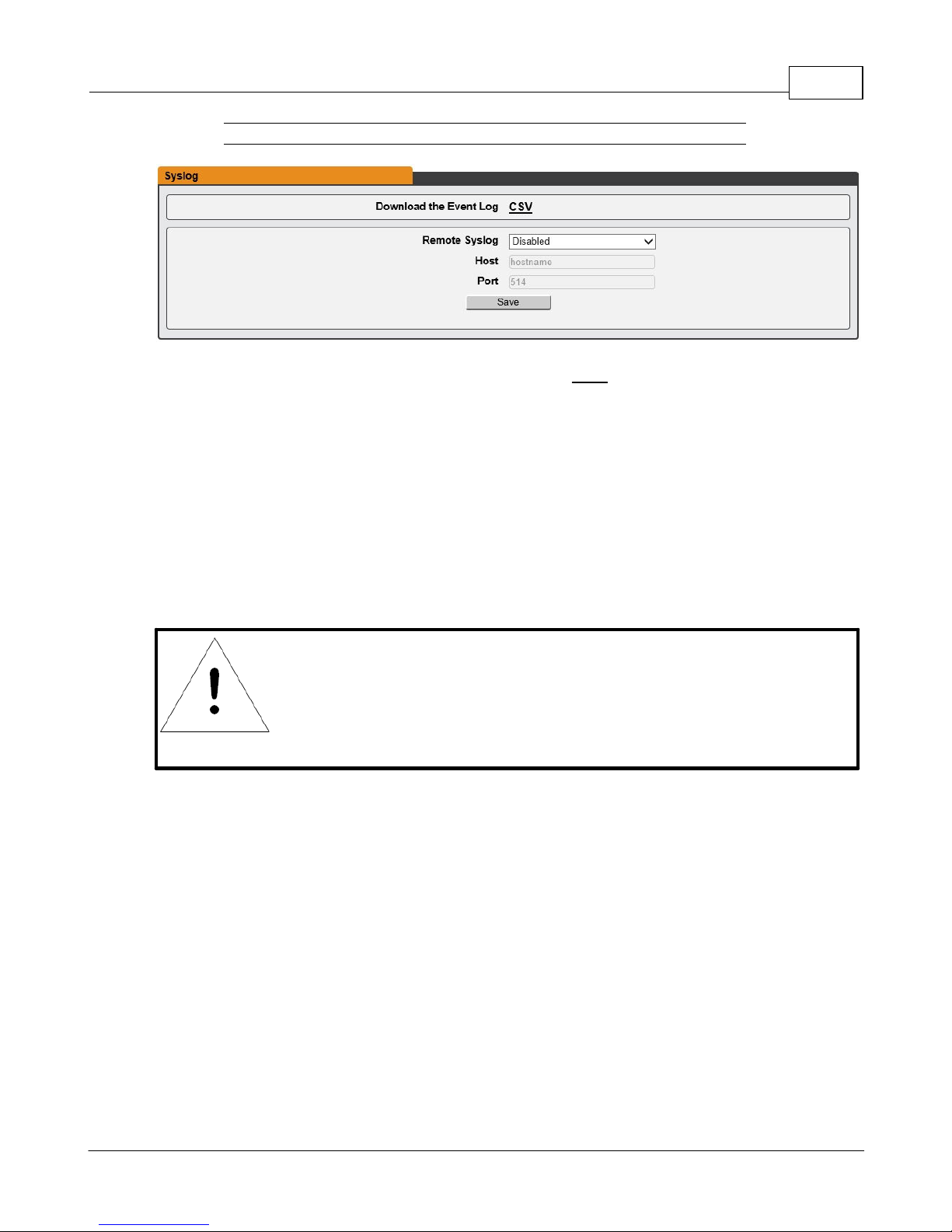
Chapter 3 - Setup 69
NOTE
This information is strictly for the users' and administrator's
convenience. The unit will not attempt to send emails to the
"Administrator Email" address and this address cannot be
chosen as the Target of an Event Action when configuring an
Alarm or Warning Event.
Figure 3-44 Syslog Configuration Page
Event log data can be downloaded by clicking on the CSV link at that top of the page. The
event log will show system events such as user logins, configuration changes, service
status, etc. The event log does not contain measurement data captured by the PDU as
that data is located in the Data Log which can be found in the Sensors -> Logging page on
the GUI.
Admin
The Admin page allows the administrator of the device to save their contact information
along with the device description and location. Once the info is saved by an administrator,
other (non-administrator) users can view the information. Also, the System Label can be
modified on this page. This label is typically shown in the title bar of the web browser's
window, and/or on the browser tab(s) currently viewing the device.
GM1196 R-Ser ies v5 Instruction Manual
© 2018 Geist
Page 70
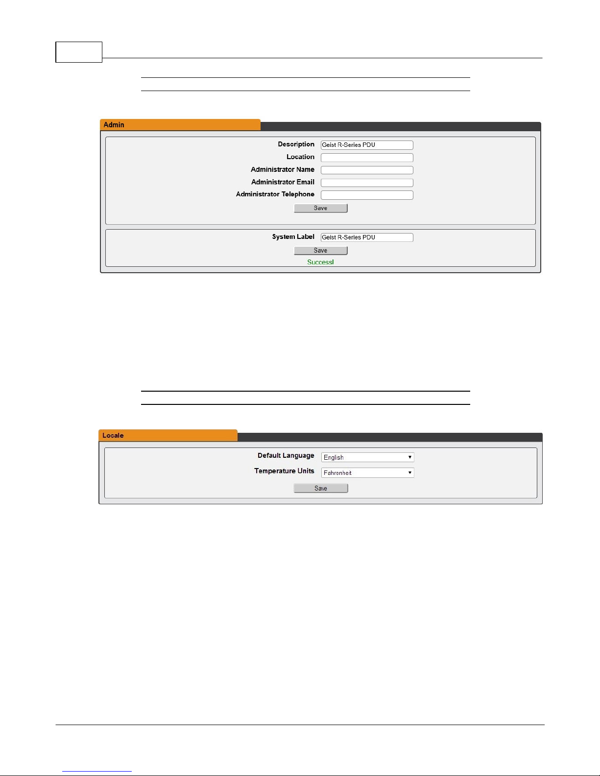
R-Series v5 Instruction Manual70
Locale
Figure 3-45 Admin Configuration Page
The Locale page sets the default Language and Temperature Units for the device. These
settings will become the default viewing options for the device, although individual users
can change these options for their own accounts. The Guest account will only be able to
view the device with the options set here.
Figure 3-46 Locale Configuration Page
Utilities
The Utilities page in the System menu provides the ability to backup/restore configuration,
restore defaults, reboot the communication system, perform firmware updates and enable
factory access.
GM1196 R-Ser ies v5 Instruction Manual
© 2018 Geist
Page 71
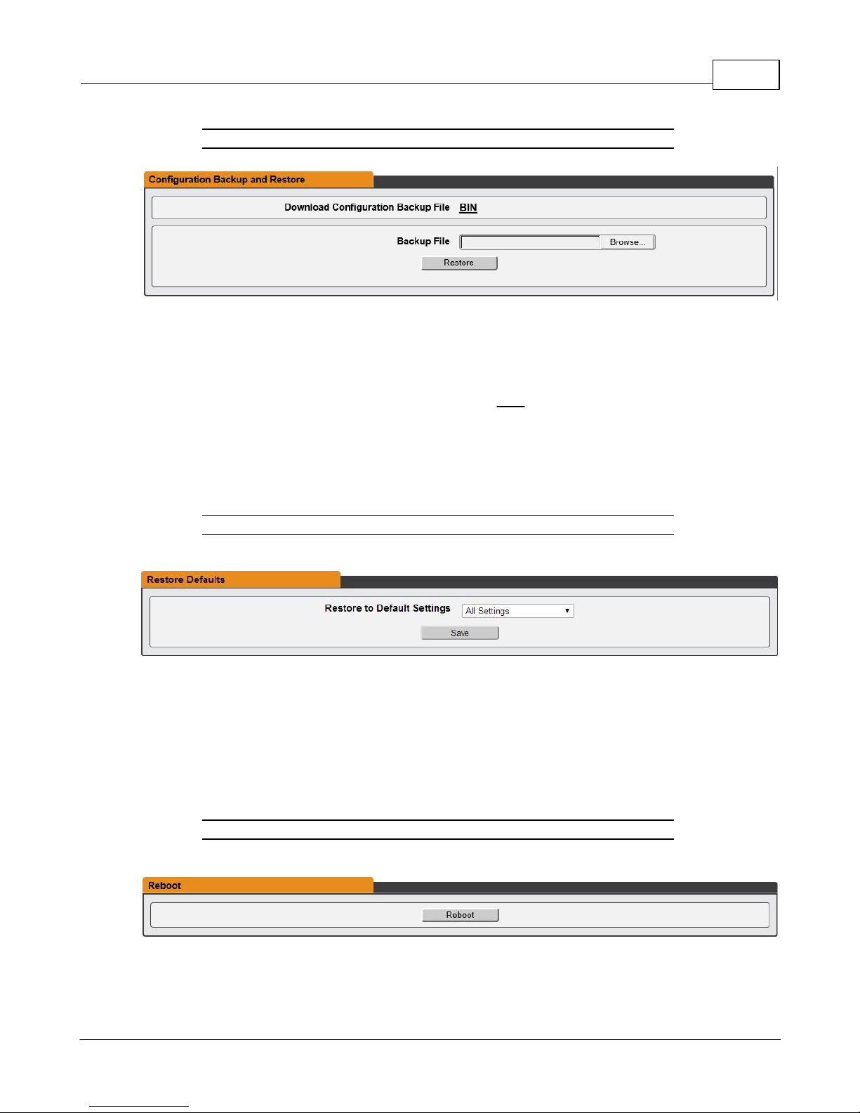
Chapter 3 - Setup 71
Figure 3-47 Configuration backup and Restore Page
The Configuration Backup and Restore section allows the user to backup the PDU
configuration file for future use in the case that the device is reset to defaults for any
reason.
To download the current configuration click on the BIN link and save the file to an easily
accessible location such as the local computer or a shared network folder.
To restore a device configuration, click the Browse button and locate the appropriate
configuration file and then click the Restore button.
Figure 3-48 Restore Default Page
The Restore Defaults section allows the user to restore the unit's settings to the factory
defaults. There are two options:
· All Settings: erases all of the unit's settings, including all Network and User Accounts
settings, effectively reverting the entire unit back to its original out-of-the-box state.
· All Non-Network Settings: erases all settings except the Network and User Accounts.
Figure 3-49 Reboot Page
The Reboot section allows the user to perform a system reboot. This function will not
affect power delivery to connected equipment.
GM1196 R-Ser ies v5 Instruction Manual
© 2018 Geist
Page 72

R-Series v5 Instruction Manual72
Figure 3-50 Firmware Update Page
Use the Firmware Update section to load firmware updates into the unit. Firmware
updates, when available, can be found on the Geist website:
http://www.geistglobal.com/support/firmware.
You can also subscribe to a mailing list, to be notified of when firmware updates become
available.
Firmware updates will typically come in a .ZIP archive file containing several files including
the firmware package itself, a copy of the SNMP MIB, a "readme" text file explaining how
to install the firmware, and various other support files as needed. Be sure to un-ZIP the
archive and follow the included instructions. Firmware updates will not affect power
delivery to connected equipment.
Figure 3-51 Factory Access Page
· Factory Access: Enabling Factory Access mode allows Geist support technicians
access to more in-depth diagnostic information. It is recommended that this option be
set to Disabled unless a Geist support member instructs you to enable it.
GM1196 R-Ser ies v5 Instruction Manual
© 2018 Geist
Page 73
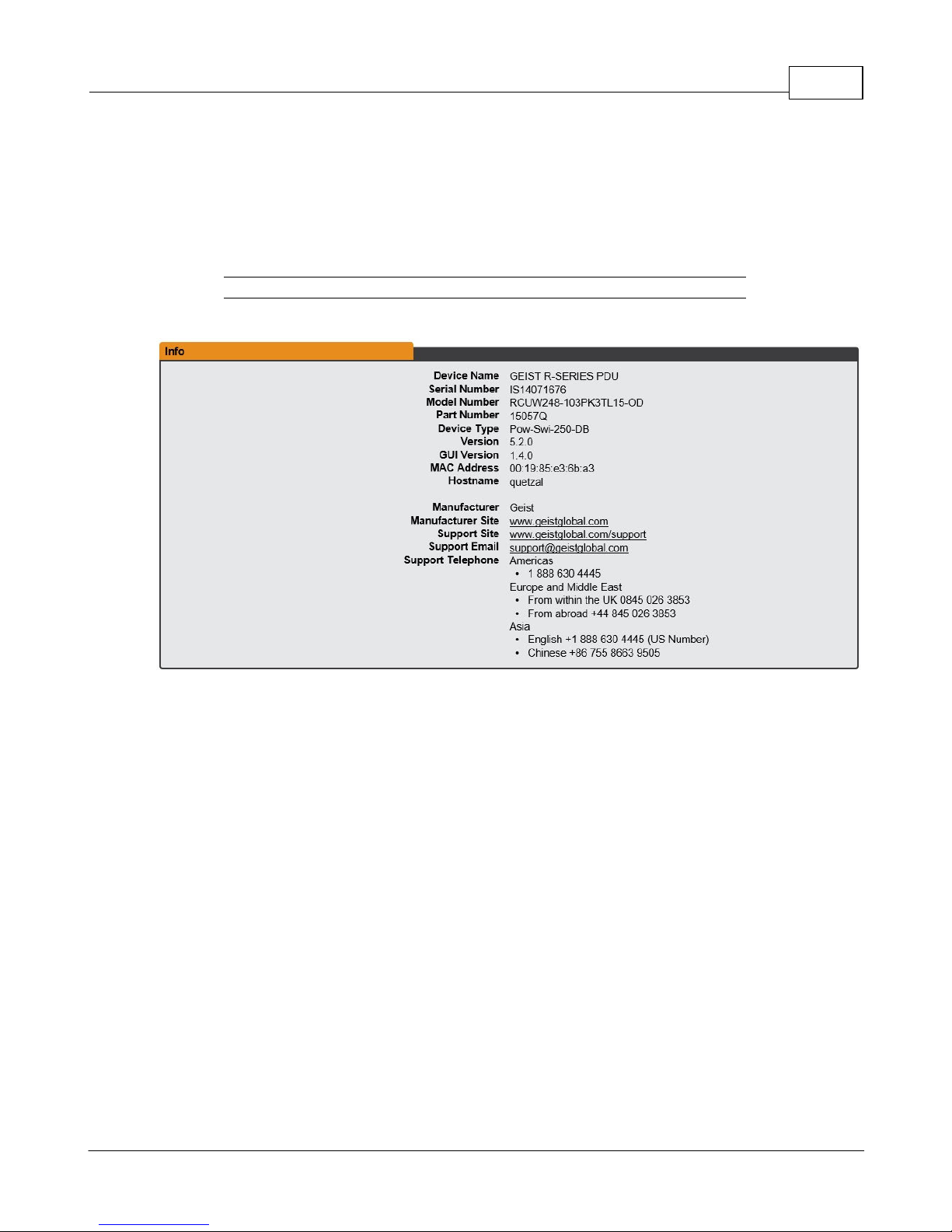
Chapter 3 - Setup 73
Help
Info
The Info Page displays the unit's current configuration information, including the device
name and ID, the type of IMD installed, the unit's current firmware versions, and network
information. Manufacturer support information is also here.
Figure 3-52 Info Page
Support Site
Technical support can be found at http://www.geistglobal.com/support
Americas
· 1 888 630 4445
Europe and Middle East
· From within the UK 0845 026 3853
· From abroad +44 845 026 3853
Asia
· English +1 888 630 4445 (US number)
· Chinese +86 755 8663 9505
GM1196 R-Ser ies v5 Instruction Manual
© 2018 Geist
Page 74
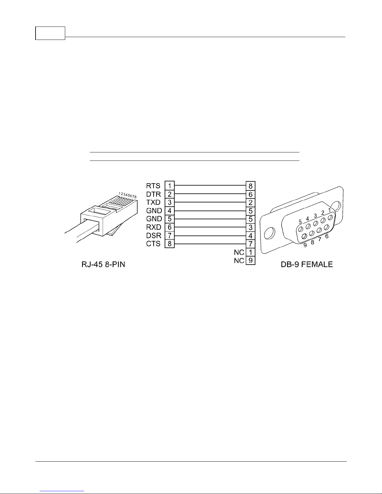
R-Series v5 Instruction Manual74
Communication
Serial Interface
The R-Series PDUs provide an out-of-band, serial monitoring interface. The unit provides
a RJ-45 port for RS-232 serial communication for out-of-band access to the units
command line interface.
Setup
The following describes how to wire a cable for communicating with the serial port on an
R-Series PDU.
Figure 3-53 Serial Interface Wiring Info Page
The following describes the parameters for serial communication with a R-Series PDU:
· Baud Rate: 9600
· Data Bits: 8
· Parity: N
· Stop Bits: 1
· Flow Control: None
Communication
Serial communication is the same as the Web API commands, but using the following
syntax:
COMMAND PATH = ARGUMENT
Command is the only required part. It is a single word from the following list: get, set,
logout, add, delete, control, ack, sendTest, reset, and reboot.
Path is the location in the tree that you want to apply the Command. Starting at the root,
each child key is separated by spaces.
Argument if present, is always preceded by an equal sign and is in JSON or YAML format.
It is only used with the following Commands: set, add, control, and reset.
GM1196 R-Ser ies v5 Instruction Manual
© 2018 Geist
Page 75
Chapter 3 - Setup 75
NOTE
Be sure to use quotes in the parameter values.
To see what the tree looks like, simply type in the following command:
get
The entire data tree is returned in YAML format. You will see some top-level keys like dev,
alarm, sys, conf, etc.
To see the system configuration, you could type:
get conf
And, paying attention to the keys returned, go any number of levels deeper:
get conf network ethernet dhcpOn
To turn DHCP off you'll use an argument:
set conf network ethernet dhcpOn = false
"set" commands are special like "get" commands in that they can be applied at any level:
set conf network ethernet = {dhcpOn: true, ip4GW:
192.168.123.1}
Many commands require a device ID, a 16 character string, which can be obtained by
calling:
get dev
Turn on outlet 1 with no delay (note outlets are 0-indexed)
control dev 0EC359E3851900C3 outlet 0 = {action: "on",
delay: "false"}
Turn off outlet 1 with no delay
control dev 0EC359E3851900C3 outlet 0 = {action: "off",
delay: "false"}
GM1196 R-Ser ies v5 Instruction Manual
© 2018 Geist
Page 76
R-Series v5 Instruction Manual76
NOTE
This will NOT affect power to the connected devices.
WARNING
Do not attempt to open the PDU or the warranty will be void.
Technical Support
Resetting PDU
Should the PDU lose communication, the following reset/reboot buttons are available to
help with troubleshooting:
1. Network-Reset Button ( ) : Located under the Ethernet port, users will need to use
a small pin or paper clip to contact this button. Holding the Network-Reset button for 5
seconds during normal operation will restore the default IP address and reset the
user accounts.
2. Hard-Reboot Button ( ): Pressing the Hard-Reboot button reboots the monitoring
device. This acts as a power-cycle for the device, and does not change or remove
any user information.
Service and Maintenance
· No service or maintenance is required.
· There are no serviceable parts inside the PDU.
GM1196 R-Ser ies v5 Instruction Manual
© 2018 Geist
Page 77
Chapter 3 - Setup 77
NOTE
These suggestions only apply if you are using your own, physical
Exchange server! Microsoft’s hosted “Office365” service utilizes a
Start-TLS connection and can be setup using the standard
"Office365" email server settings in the email configuration menu.
Using Microsoft Exchange as an SMTP server
If your facility uses a Microsoft Exchange email server, it can be used by the R-Series PDU
to send Alarm and Warning notification emails if desired. However, the Exchange server
may need to be configured to allow SMTP connections from the unit first, as later version
of Exchange often have SMTP services or basic authentication disabled by default. If you
encounter difficulties in getting your IMD PDU to send emails through your Exchange
server, the following notes may be helpful in resolving the problem.
First, since the R-Series PDU cannot use IMAP or Microsoft’s proprietary MAPI/RPC
Exchange/Outlook protocols to send messages, you will need to enable SMTP by setting
up an “SMTP Send Connector” in the Exchange server. More information on setting up an
SMTP Send Connector in Exchange can be found at this Microsoft TechNet article:
http://technet.microsoft.com/en-us/library/aa997285.aspx
Next: Your Exchange server may also need to be configured to allow messages to be
“relayed” from the monitoring unit. Typically, this will involve turning on the “Reroute
incoming SMTP mail” option in the Exchange server’s Routing properties, then adding
the PDU’s IP address as a domain which is permitted to relay mail through the Exchange
server. More information about enabling and configuring SMTP relaying in Exchange can
be found at this Microsoft TechNet article: http://technet.microsoft.com/en-
us/library/dd277329.aspx
The SMTP “AUTH PLAIN” and “AUTH LOGIN” authentication methods (also known as
“Basic Authentication) for logging in to the server are often no longer enabled by default in
Exchange; only Microsoft’s proprietary NTLM authentication method is enabled. The
AUTH LOGIN method which the IMD PDU requires can be re-enabled as follows:
1. In the Exchange console under server configuration, select hub transport.
2. Right-click the client server, and select properties.
3. Select the authentication tab.
4. Check the Basic Authentication checkbox.
5. Uncheck the Offer Basic only after TLS checkbox.
6. Apply or save these changes, and exit. Note that you may need to restart the
Exchange service after making these changes.
Finally, once you have enabled SMTP, relaying, and the AUTH LOGIN Basic Authentication
method, you may also need to create a user account specifically for the PDU to log into.
If you have already created an account prior to enabling the SMTP Send Connector, or
you are trying to use an already-existing account created for another user, and the PDU
still cannot seem to connect to the Exchange server, the account probably did not
properly inherit the new permissions when you enabled them as above. This tends to
happen more often on Exchange servers that have been upgraded since the account(s)
you are trying to use were first created, but can sometimes happen with accounts when
GM1196 R-Ser ies v5 Instruction Manual
© 2018 Geist
Page 78

R-Series v5 Instruction Manual78
new connectors and plug-ins are added regardless of the Exchange version. Delete the
user account, then create a new one for the monitoring unit to use, and the new account
should inherit the SMTP authentication and mail-relaying permissions correctly.
If none of the above suggestions succeed in allowing your Geist R-Series PDU to send
mail through your Exchange server, then you may need to contact Microsoft’s technical
support for further assistance in configuring your Exchange server to allow SMTP emails
to be sent from a 3rd-party, non-Windows device through your network.
GM1196 R-Ser ies v5 Instruction Manual
© 2018 Geist
Page 79
Chapter 4 - Final Checkout
DANGER
HAZARDOUS VOLTAGE, CURRENT, AND ENERGY LEVELS
ARE PRESENT IN THIS PRODUCT. POWER SWITCHED
CIRCUITS CAN HAVE HAZARDOUS VOLTAGES PRESENT
EVEN WHEN THE SWITCH IS IN THE OFF POSITION. DO
NOT OPERATE THE PRODUCT WITH ANY COVER PLATE
REMOVED. ALWAYS MAKE SURE THAT PRODUCT IS
FULLY ENCLOSED PRIOR TO USE.
Product-Specific Safety Notices
The specific procedural safety precautions relating to this product are stated
below.
General Safety
Safety is a serious matter and all precautions should to taken to guarantee a
safe work and operational environment. General safety precautions must be
observed during all aspects of operation, service, and repair of equipment
described in this document. Failure to comply with the safety warnings,
procedures and guidelines as presented in this document is in violation of the
safety standards of design, manufacture, and intended use of this equipment.
You are responsible for following the safety guidelines and warnings presented
in this document for this equipment. Individuals using or maintaining Geist
product(s) are expected to follow all the noted warnings and safety precautions
necessary for safe operation of the equipment in your environment. Geist
assumes no liability for failure to comply with these requirements.
Chapter 3 - Setup 79
Live Circuits Safety
Operating personnel must:
· Not remove equipment covers. Only Geist Authorized Service Personnel or
other qualified maintenance personnel may remove equipment covers for
internal sub-assembly, or component replacement, or any internal adjustment.
· Not replace any equipment component with power applied to the line cord.
GM1196 R-Ser ies v5 Instruction Manual
Under certain conditions, dangerous voltages may exist even with the input
power cable disconnected. Any exceptions for 'Hot-Swap' modules will be
specifically noted in this product document.
© 2018 Geist
Page 80

R-Series v5 Instruction Manual80
· Always disconnect input power and discharge circuits before touching any
sub-assembly of circuit component.
Equipment Grounding
To minimize shock hazard, the equipment chassis and enclosure must be
connected to an electrical earth ground. The input power cable must be either
plugged into an industry electrical code compatible receptacle or wired directly
into an electrical code compatible interface. The equipment earth ground wire
(typically green) must be firmly connected to the facility electrical safety ground.
The mating electrical interface to this equipment must comply with International
Electromechanical Commission (IEC) standards.
Electrostatic Discharge
Geist strongly recommends that an anti-static precautions be taken when
installing, removing, or working on and around static sensitivity equipment.
Industry approved anti-static devices such as wrist and heel straps, in
conjunction with conductive foam pads, should be available and implemented
only after verifying that they are in good working condition.
Electronic components such as memory modules, circuit boards, and LED
displays, are sensitivity to Electro-Static Discharge (ESD). Handling of such
components should be done only after proper anti-static workspace conditions
have been established. Any static producing packing materials such as plastic,
Styrofoam, and some cardboards, should be removed and discarded in a timely
manner.
Explosive Environment
Do not operate this equipment in the presence of flammable gases or fumes.
Operation of any electrical equipment in such an environment constitutes a
definite safety hazard.
Servicing and Adjustments
Do not attempt to service this equipment, there are no field serviceable parts or
sub-assemblies. Any adjustments should be made by authorized service
personnel only.
Repairs and Modifications
Because of the danger of electrocution and/or severe health hazard, do not install
substitute parts or preform any unauthorized modifications of this equipment. It is
GM1196 R-Ser ies v5 Instruction Manual
© 2018 Geist
Page 81

Chapter 4 - Final Checkout 81
best to contact Geist for Warranty and Repair Service to ensure that safety
features are maintained.
GM1196 R-Ser ies v5 Instruction Manual
© 2018 Geist
Page 82

Thank You For
Purchasing Geist
geistglobal.com
 Loading...