

Page 1

43R-1000E
1/99
OPERATION AND MAINTENANCE MANUAL
AUTOMATIC TRANSFER SWITCH
ZTSH SERIES
30-4000 AMPS
ISO 9001
Page 2

Page
Introduction ............................................................................................................................................................................................1
Installation ................................................................................................................................................................................................2
Equipment Inspection and Storage......................................................................................................................2
Mounting ......................................................................................................................................................................................2
Power Connections..............................................................................................................................................................3
Control Connections ..........................................................................................................................................................3
Final Equipment Inspection........................................................................................................................................4
Functional Test ........................................................................................................................................................................6
Operation and Features
................................................................................................................................................................7
Sequence of Operation
.................................................................................................................................................. 7
Zenith Module 9 Accessory Package..................................................................................................................8
Zenith Optional Accessories ......................................................................................................................................9
Maintenance and Testing..........................................................................................................................................................10
Inspection and Cleaning ..............................................................................................................................................10
Servicing......................................................................................................................................................................................10
Testing ..........................................................................................................................................................................................10
Troubleshooting ..................................................................................................................................................................12
Adjustments and Settings ........................................................................................................................................................10
Solid State Timers..............................................................................................................................................................10
Voltage/Frequency Sensor VFSM ......................................................................................................................10
Solid State Phase Relays..............................................................................................................................................10
Electronic Exercise Clock Z1000-1A ..............................................................................................................12
Electronic Exercise Clock Z2000-2A ..............................................................................................................12
Appendix A—Typical Schematic Diagrams ............................................................................................................12
40 to 150 Amp, Series 2, ZTSH Switches ....................................................................................................12
40 to 260 Amp Switches ..............................................................................................................................................12
400 Amp Switches..............................................................................................................................................................12
600 to 1200 Amp Switches ........................................................................................................................................12
1600 to 4000 Amp Switches......................................................................................................................................12
Appendix B—Replacement Parts ....................................................................................................................................12
Power Panel 40 to 150 Amp, Series 2, ZTSH Switches ..................................................................12
Power Panel 40 to 260 Amp Switches..............................................................................................................12
Power Panel 400 Amp Switches ............................................................................................................................12
Power Panel 600 to 1200 Amp Switches........................................................................................................12
Power Panel 1600 to 3000 Amp Switches ....................................................................................................12
Power Panel 4000 Amp Switches ........................................................................................................................12
Standard Control Panel SSRCP............................................................................................................................12
Optional Control Panel ................................................................................................................................................12
Cabinet Door Pivot Devices ....................................................................................................................................12
Table of Contents
Page 3

Zenith Transfer Switches are used to provide a continuous source of power for lighting and
other critical loads by automatically transferring from the normal source of power to an emergency source of power in the event that the normal source voltage falls below preset limits.
All Zenith transfer switches are designed for use on emergency or standby systems, and
are rated for total system or motor loads. Transfer switches are UL Listed under Standard
1008 and CSA Certified under Standard C22.2 No. 178.
This manual provides information on the installation, operation and maintenance of the
switch. In addition, a complete information package is supplied with each transfer switch
which details the features and accessories provided on that switch. The information package and the instruction manual should be kept in a readily accessible location to provide
complete reference information on this critically important piece of equipment.
Introduction
■■
Zenith Controls, Inc. 1
■■
ZTSH Operation and Maintenance Manual (43R-1000)
Page 4

■■
2 Zenith Controls, Inc.
■■
ZTSH Operation and Maintenance Manual (43R-1000)
Each Zenith transfer switch is factory wired and tested. A complete information package
is furnished with each switch which includes:
a. Sequence of operation.
b. Description and operation of all accessories supplied.
c. Power panel connection diagram and schematic.
d. Description and identification of all customer field connections.
Installation of Zenith transfer switches includes:
a. Mounting the transfer switch cabinet.
b. Connection of all Normal, Emergency, and Load cables or bus bars.
c. Connection of external control circuits as required.
Equipment Inspection and Storage
Immediately inspect the transfer switch when received to detect any damage which may have
occurred during transit. If damage is found or suspected, file claims as soon as possible with
the carrier and notify the nearest Zenith representative.
Before installation, it is necessary to store the transfer switch in a clean dry place, protected from
dirt and water. Provide ample air circulation and heat, if necessary, to prevent condensation.
Storage Temperature: -30° C to + 85° C (-22° F to +185° F)
Operating Temperature (Ambient): -20° C to +75° C (-4° F to +167° F) [30-260 Amps]
-20° C to +40° C (-4° F to +140° F) [400-800 Amps]
Humidity: 5% to 95% (non-condensing)
Mounting
Adequate lifting means must be used to mount the transfer switch into place. The recommended
method for moving the transfer switch using the lifting eyes, where supplied, and a spreader
bar is illustrated in Figure 1. Enough room should be allowed to open the cabinet doors fully
for inspection and servicing of the switch per NEC and local codes.
Before drilling conduit entry holes or any accessory mounting holes, cover and protect the switch
and control panel to prevent dirt and metal fragments from entering the mechanical and
electrical components. Failure to do so may result in damage and malfunction of the switch.
Installation
DANGER
HAZARDOUS VOLTAGE
(Can Cause Severe Injury or Death)
Turn OFF all power before installation, adjustment, or removal of transfer switch or any of its components.
Page 5

■■
Zenith Controls, Inc. 3
■■
ZTSH Operation and Maintenance Manual (43R-1000)
D
CABINET
LIFTING EYES
SPREADER BAR
H
45°
Figure 1
NOTICE
When lifting the switch using a spreader bar, height H must be equal to half of distance D.
Installation (cont’d)
Table 2
Tightening Torque for Lugs
Socket Size
Across Flats
Torque
Lb. - In. Lb. - Ft.
451/8 4
1005/32 8
1203/16 10
1507/32 12
2001/4 17
2755/16 23
3753/8 31
5001/2 42
6009/16 50
Table 3
Tightening Torque for Bus Bars
Bolt Size
Torque Bolt (Grade 5)
Lb. - In. Lb. - Ft.
721/4-20 6
1325/16-18 11
3003/8-16 25
7201/2-13 60
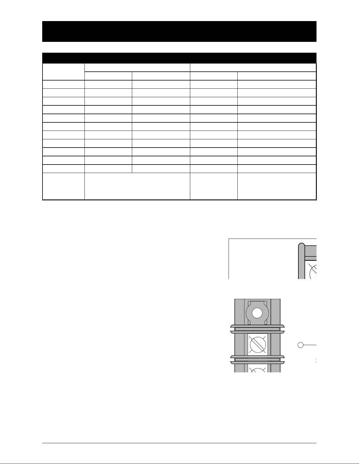
Power Connections
Zenith transfer switches are supplied with
UL listed solderless screw type terminals
as standard for the Normal, Emergency and
Load power connections. Table 1 lists the
number and sizes of cable lugs supplied
as standard for each switch amp rating.
Connect the Normal, Emergency, and Load
conductors to the clearly marked terminals
on the transfer switch. Remove surface
oxides from cables by cleaning with a wire
brush. Verify that all connections are correct before tightening the lugs. All cable
lug connections must be tightened to the
proper torque values as shown in Table 2.
Do not run cables or wiring behind frontconnected transfer switches.
In cases where the Normal, Emergency and
Load connections are made to a rear connected bus bar, a compression washer, flat
washer, and a minimum grade 5 bolt must
be used and torqued to the values in Table 3.
Page 6
Control Connections
A complete information package is furnished with each
transfer switch including a complete connection diagram
and schematic which details all necessary control circuit
field connections.
The engine start control wires connect to the terminals
specified in the upper left corner of the control panel.
Figure 2 shows the location of these terminals on the standard SSRCP printed circuit board mounted on the steel
backplate. These terminals are clearly identified by a preprinted label attached to the steel control panel. In the
case of manual transfer switches, or in other applications
not requiring the standard control panel, clearly marked
terminal blocks are provided in the upper left corner of
the control panel for the engine start control wires.
Terminals for field connections to the A3 Emergency auxiliary contacts and the A4 Normal auxiliary contacts are also
provided. These terminals are clearly marked and appear on
the side of the power panel. On 400 amp units these terminals
appear on the disconnect switch bracket above the operator
handle, and are marked as illustrated in Figure 3.
Figure 2
ENGINE
■■
4 Zenith Controls, Inc.
■■
ZTSH Operation and Maintenance Manual (43R-1000)
Installation (cont’d)
Figure 3
Table 1
Screw Type Terminals for External Power Connections
Switch Size
(Amps)
40
80
100
150
225
260
400
600
800
Normal, Emergency & Load Terminals
1 #8 to 2 AWG
Cable Per Pole Range of Wire Sizes
1000
1200
1600
2000
3000
4000
1 #8 to 1/0 AWG
1 #8 to 1/0 AWG
1 #8 to 3/0 AWG
1 #6 AWG to 250 MCM
1 #6 AWG to 350 MCM
1 #4 AWG to 600 MCM
2 #2 AWG to 600 MCM
4 #2 AWG to 600 MCM
Fully Rated Neutral Bar (When Required)
3 #8 to 1/0 AWG
No. of Cables Range of Wire Sizes
3 #8 to 1/0 AWG
3 #8 to 1/0 AWG
3 #6 AWG to 300 MCM
3 #6 AWG to 300 MCM
3 #6 AWG to 300 MCM
4 #2 AWG to 600 MCM
8 #2 AWG to 600 MCM
12 #2 AWG to 600 MCM
4 #2 AWG to 600 MCM 12 #2 AWG to 600 MCM
4 #2 AWG to 600 MCM 12 #2 AWG to 600 MCM
Line and load terminals are located
in rear and arranged for bus bar
connection.
12
12
12
12
3/0 AWG to 750 MCM
3/0 AWG to 750 MCM
3/0 AWG to 750 MCM
3/0 AWG to 750 MCM
A3-2
Page 7

■■
Zenith Controls, Inc. 5
■■
ZTSH Operation and Maintenance Manual (43R-1000)
Make all other necessary external control connections to the appropriate terminal blocks located
on the control panel. Insure that all connections
are tightened to the torque specified in Figure 4.
Final Equipment Inspection
Prior to energizing the transfer switch:
a. Remove any debris incurred due to shipment or installation.
DO NOT use a blower
since debris may become lodged in the electrical and mechanical components and
cause damage. Use of a vacuum is recommended.
b. Verify that all cabled connections are correct and that phase rotation of both
sources match.
c. Check engine start connections and verify the correct connection of all control wires.
d. Check settings of all timers and adjust as necessary. Also adjust any optional acces-
sories as required.
e. Check the integrity of power connections by verifying actual lug torque values as
specified in this manual.
f. Make sure that all covers and barriers are installed and properly fastened.
Functional Test
The functional testing of the transfer switch consists of manual and electrical tests described
in this section. Before proceeding, refer to the information package supplied with the transfer
switch. Read and understand all instructions and review the operation of all accessories provided.
A manual operator handle is provided with the transfer switch for maintenance purposes
only. Manual operation of the switch must be checked before it is operated electrically.
Both power sources
MUST be disconnected before manual operation of the switch. Insert
the handle and operate the transfer switch between the Normal and Emergency positions.
The transfer switch should operate smoothly without binding. Return the switch to the
Normal position, remove the handle, and return it to the holder provided.
Before starting the electrical operation test,
check the equipment rating nameplate on the
transfer switch to verify the correct system
voltage. An example of the equipment rating
nameplate is shown in Figure 5.
First, close the Normal source circuit breaker.
The phase relays B1, B2, and B3 will pick up
and the LED indicators will be illuminated.
Verify the phase to phase voltages at the
Normal line terminals.
Installation (cont’d)
Figure 4
Control Wire Connections
Wire Size (AWG)
18-16
14-8
6-4
Torque Lb. - In.
19
19
36
Figure 5
SERIAL NUMBER:
RATING: VOLTS -
AMPS SYSTEM VOLTS:
MODEL NUMBER:
HZ -
PHASE -
Page 8

■■
6 Zenith Controls, Inc.
■■
ZTSH Operation and Maintenance Manual (43R-1000)
Next, close the Emergency source breaker and start the engine generator. The VFSM relay
will pick up and the LED indicator will be illuminated. Check the phase to phase voltages at
the Emergency line terminals. Also, verify that the phase rotation of the Emergency source is
the same as the phase rotation of the Normal source.
After the sources have been verified, shut down the engine generator, and put the starting
control in the automatic position. Complete the visual inspection of the transfer switch,
and close and lock the cabinet door.
Initiate the electrical transfer test by activating the TS test switch. The CR control relay will
drop out and the P1 engine start timer will start its timing cycle.
After the P1 timer has completed its timing cycle, the engine start contact will close and signal
the engine generator to start. The VFSM relay will energize. The switch will transfer to the
Emergency source after the time delay of the W timer.
Deactivating the test switch will start retransfer to the Normal source. The switch will retransfer to the Normal source after the time delay of the T timer. The U engine over-run timer allows
the engine generator to run unloaded for a preset cool down time period.
Installation (cont’d)
NOTICE
A periodic test of the transfer switch under load conditions is recommended to insure proper operation.
(See National Electric Code articles 700 and 701).
Page 9

■■
Zenith Controls, Inc. 7
■■
ZTSH Operation and Maintenance Manual (43R-1000)
Sequence of Operation
Figure 6 is a typical schematic diagram of a Zenith transfer switch with a Module 9 accessory
package. The information package supplied with the transfer switch includes a schematic
diagram and description of operation of all accessories provided.
The sequence for load transfer to the Emergency source begins automatically when any
phase of the Normal source falls below the preset dropout point and this undervoltage
failure condition is detected by the solid state phase relays B1, B2, B3.
The phase relays drop out, de-energizing the normal control relay CR, and engine start timer P1
begins its timing cycle. The P1 time delay is provided to override momentary outages and to prevent
nuisance starting of the engine generator. If the Normal source voltage returns above the pickup setting of the phase relays, the P1 timing cycle is reset to zero by the re-energization of the CR relay.
If the normal source voltage does not return before the P1 time delay is completed, the P1 timer
drops out and sends a starting signal to the engine generator. An emergency voltage and frequency sensing relay VFSM monitors the voltage and frequency of the Emergency source. When
both the voltage and the frequency of the Emergency source reach the preset pickup points,
the VFSM relay initiates the transfer to the Emergency source and timer W begins its timing
cycle. The W timer provides an adjustable transfer delay to the Emergency source as required.
When the W time delay is completed, the Emergency control relay RT energizes and picks
up the power relay, CE1 or CCE. The power relay connects voltage from the Emergency
source to the Emergency switch operating circuit caaausing the switch to transfer its main
contacts to the Emergency source. The switch is mechanically locked in the Emergency
position. The power relay and Emergency operator are de-energized when the SE limit
switch is activated by the operator. The SN limit switch is deactivated at the same time,
readying the Normal control circuit for retransfer when the Normal source is restored.
The sequence for retransfer to the Normal source begins automatically when the voltage
on all phases of the Normal source reach the preset pickup point and this condition is
detected by the solid state phase relays.
When the Normal source restores, the solid state phase relays B1, B2, B3 pick up and initiate
retransfer of the switch to the Normal source by energizing timer T and beginning its timing
cycle. The T timer provides an adjustable delay to ensure that the Normal source has stabilized
before reconnection to the load. If the Normal source fails before the T time delay is completed, the phase relays drop out and the T timing cycle is reset to zero.
When the T time delay is completed, the Normal control relay CR energizes and picks up the
power relay, CN1 or CNN. The power relay connects voltage from the normal source to the
Normal switch operating circuit causing the retransfer of the main switch contacts to the
normal source. The switch is mechanically locked in the Normal position. The power relay and
the Normal operator are de-energized when the SN limit switch is activated by the operator.
The SN limit switch also energizes the engine over-run timer U and begins its timing cycle.
The timer provides a period of timefor the engine generator to run without load and cooldown
before shutdown. After the U time delay is completed, the P1 timer is energized and the
engine generator is shutdown.
Operation and Features
Page 10

■■
8 Zenith Controls, Inc.
■■
ZTSH Operation and Maintenance Manual (43R-1000)
N3
T3
N2
T2
N1
T1
NN
TN
E3
E2
E1
EN
22
21
20
32
31
30
16
15
20B121 22
CCN
323130
E1,2,3,N - EMERGENCY LINE
T1,2,3,N - LOAD
N1,2,3,N - NORMAL LINE
SWITCHED NEUTRAL OR
SOLID NEUTRAL IF REQUIRED
CR
CR
T
B1 B2 B3
CR
C
NC
NO
U
P1
CCN
23
23A 23B 23C
23Z
28
26
28Z
29
J1
J2
J3
J4
J7
CCN - POWER RELAY, ENERGIZES TRANSFER
TO NORMAL SOLENOID
W
RT
W - TIME DELAY TO EMERGENCY
RT - EMERGENCY CONTROL RELAY
CCE - POWER RELAY, ENERGIZE
VFSM- EMERGENCY VOLTAGE AND
FREQUENCY SENSING RELAY
VFSM
L2
27
RT
J5
T
U
25Z
P1
ENGINE START CONTACT FROM P1
LEGEND
WIRE CONNECTION
WIRE ON MAIN TERMINAL BLOCK
WIRE ON DISCONNECT PLUG
OPTIONAL ACCESSORY
A4
NORMAL
SN
A3
EMERGENCY
MECHANICALLY ACTUATED
NORMAL AND EMERGENCY
POSITION CONTACTS A3 & A4
B2
B3
CE - TRANSFER TO EMERGENCY SOLENOID
CN -TRANSFER TO NORMAL SOLENOID
DS - DISCONNECT SWITCH FOR SERVICE
XN - NORMAL CONTROL TRANSFORMER
XE - EMERGENCY CONTROL TRANSFORMER
UNDER VOLTAGE RELAYS
COM
TS
YN
J8
J6
J9
CR
33Z
37
W
RT
J10
2524
C
NC
NO
CCE
36
L1
35Z
SE
J11
3534
33Y
VFSM
33A
33
RT
38
RT
CR
12A
13
11
12
T - TIME DELAY ON RETRANSFER
CR - CONTROL RELAY
YN - PUSH BUTTON TO BYPASS T
L2 - NORMAL POSITION LIGHT
U - ENGINE OVER-RUN TIMER
P1 - TIME DELAY TO ENGINE START
SN - MECHANICALLY ACTUATED CONTACTS
(NORMAL POSITION)
SE - MECHANICALLY ACTUATED CONTACTS
(EMERGENCY POSITION)
L1 - EMERGENCY POSITION LIGHT
CN
206209
CCE
CE
306307
DS
NOTE - ZTSH SHOWN IN NORMAL POSITION WITH NO POWER AVAILABLE
NN EN
14
Figure 6
Typical Schematic Diagram
Operation and Features (cont’d)
Page 11

■■
Zenith Controls, Inc. 9
■■
ZTSH Operation and Maintenance Manual (43R-1000)
Zenith Module 9 Accessory Package
The Zenith Module 9 Accessory package includes nine of the commonly specified accessories.
These accessories are:
A Auxiliary Contacts:
A3 Closed when switch is in emergency position
L Indicating LED Pilot Lights:
L1 Indicates switch in emergency position
L2 Indicates switch in normal position
P1 Time Delay - Engine Start: Adjustable 0.5 to 6 seconds
T200 Time Delay on Retransfer to Normal: To delay retransfer to normal source (immediate
retransfer on generator set failure); standard setting 30 minutes, adjustable 0-60 minutes.
T100 Time Delay on Retransfer to Normal: To delay retransfer to normal source (immedi-
ate retransfer on generator set failure); standard setting 30 min., adjustable 0-30 min.
T3/W3Time Delays - Presignal for Auxiliary Control: Prior to transfer between two live
sources in either direction, provides an adjustable (factory set at 20 second) presignal contact closure
U200 Time Delay for Engine Cooldown: Allows engine to run unloaded after switch
retransfers to normal. Standard setting 5 min., adjustable 0-60 minutes.
U100 Time Delay for Engine Cooldown: Allows engine to run unloaded after switch
retransfer to normal; standard setting 5 min., adjustable 0-5 min.
W200 Time Delay on Transfer to Emergency: To delay transfer to emergency after nor-
mal source failure; standard setting 1 sec., adjustable 0-5 minutes.
W100 Time Delay on Transfer to Emergency: To delay transfer to emergency after verifying
emergency source available; standard setting 1 sec., adjustable 0-15 sec.
Operation and Features (cont’d)
Page 12

■■
10 Zenith Controls, Inc.
■■
ZTSH Operation and Maintenance Manual (43R-1000)
Operation and Features (cont’d)
Zenith Optional Accessories
Many control accessories are available to meet specific requirements. Some of the more
commonly specified accessories are:
A Auxiliary Contacts:
A6 Deenergizes external motor control circuit5 seconds (adjustable) prior to
transfer in either direction.
C Plant Exerciser (no load): Automatically starts the generator to run unloaded at
selected intervals
C/D Plant Exerciser (Load/no load): Allows the generator to start and run unloaded
or to simulate a power failure, start generator and run under load. Specify weekly,
bi-weekly or calendar schedule
L Indicating LED Pilot Lights:
L3 Indicates normal source available
L4 Indicates emergency source available
P2 Time Delay - Engine Start: Adjustable 0.5 to 300 seconds
Q2 Peak Shave/Remote Load Test: Input for peakshave or remote load test; includes
automatic return to normal if emergency source fails and normal is present; 120
VAC or 24 VDC
R4 In-Phase Monitor: Prevents transfer until two sources are in relative synchronism
R43 In-Phase Monitor: Prevents transfer until two sources are in relative synchronism
S1 Four-position selector switch (Stop - Hand Crank - Test - Automatic)
S2 Disconnect switch in series with accessory E to disconnect engine-starting circuit
S3 Source selector switch circuit; to select either source as primary
T3/W3Time Delays - Presignal for Auxiliary Control: Prior to transfer between two live
sources in either direction, provides an adjustable (factory set at 20 second) presignal
contact closure
W100 Time Delay on Transfer to Emergency: To delay transfer to emergency after verifying
emergency source available; standard setting 1 sec., adjustable 0-15 sec.
YEN Pushbutton Bypass of T&W Timers
Page 13

■■
Zenith Controls, Inc. 11
■■
ZTSH Operation and Maintenance Manual (43R-1000)
A preventive maintenance program will insure high reliability and long life for the transfer
switch. The preventive maintenance program for the transfer switch should include the
following items:
Inspection and Cleaning
Before doing any work on the transfer switch, de-energize all sources of power. The switch
should be inspected for any accumulation of dust, dirt, or moisture, and should be cleaned
by vacuuming or wiping with a dry cloth or soft brush.
DO NOT use a blower since debris
may become lodged in the electrical and mechanical components and cause damage.
Remove the transfer switch barriers or arch chutes and check the condition of the contacts.
Any surface deposits must be removed with a clean cloth (
DO NOT USE EMERY CLOTH OR A
FILE
). If the contacts are worn excessively, they should be replaced. A general inspection of
mechanical integrity should be made to include loose, broken or badly worn parts.
Servicing
All worn or inoperative parts must be replaced using Zenith recommended replacement
parts. Appendix B at the back of this manual includes replacement part information for
typical power and control panel configurations. When ordering parts provide the model
number or serial number from the transfer switch rating nameplate.
Please refer to the Replacement Parts manual for specific part information and ordering
procedures. Please contact the Zenith Technical Services Department for the Replacement
Parts manual.
The operating mechanism of the transfer switch is lubricated with Lubriplate 105. The
lubricant applied at the factory provides adequate lubrication for the lifetime of the switch.
Should debris contaminate the mechanism, clean and apply additional Lubriplate.
Zenith can provide complete preventative maintenance services. Please contact the Zenith
Technical Services Department for additional information.
Maintenance and Testing
DANGER
HAZARDOUS VOLTAGE
(Can Cause Severe Injury or Death)
Turn OFF all power before installation, adjustment, or removal of transfer switch or any of its components.
Page 14

■■
12 Zenith Controls, Inc.
■■
ZTSH Operation and Maintenance Manual (43R-1000)
Testing
A manual operator handle is provided with the transfer switch for maintenance purposes
only. Manual operation of the switch must be checked before it is operated electrically.
Both power sources
MUST be disconnected before manual operation of the switch. Insert
the handle and operate the transfer switch between the Normal and Emergency positions.
The transfer switch should operate smoothly without binding. Return the switch to the
Normal position, remove the handle, and return it to the holder provided.
After completing the inspection, cleaning and servicing of the transfer switch, reinstall the
switch cover, and close and lock the cabinet door. Reclose the circuit breakers feeding the
utility and generator sources to the switch.
Initiate the electrical transfer test by activating the TS test switch. P timer will time out and the
microcontroller will send an engine start signal. When the W time has elapsed, the switch will
complete its transfer by closing into the Emergency source.
Deactivating the test switch will start retransfer to the Normal source. The switch will complete
its retransfer to Normal after the time delay of the T timer. The U engine overrun timer allows
the engine generator to run unloaded for a preset cool down period.
Maintenance and Testing (cont’d)
NOTICE
A periodic test of the transfer switch under load conditions is recommended to insure proper operation.
(See National Electric Code articles 700 and 701).
Page 15

■■
Zenith Controls, Inc. 13
■■
ZTSH Operation and Maintenance Manual (43R-1000)
Maintenance and Testing (cont’d)
Annunciation Possible Cause Corrective Action
Engine Does Not STOP
Delay to Engine Stop LED on
Normal Available, Normal Position,
and Emergency Available LEDs on
U timing cycle not complete
Engine start wires not
terminated correctly
Generator in “Manual”
Check U Timer setting
Check Engine Start Connections
Investigate why the Engine Control
Switch was put in manual
Annunciation Possible Cause Corrective Action
ATS Will Not Transfer To EMERGENCY
Emergency Available LED off
None
Normal Position and Emergency
Position flashing
Delay to Open Normal LED on
Emergency voltage or frequency
not within acceptable parameters
Power supply harness unplugged
Limit switch harness unplugged
W timing cycle not complete
Check Engine Start Connections,
Generator Breaker, Generator
output, and Engine Control Switch
Plug in harness
Plug in harness
Check W Timer setting
Annunciation Possible Cause Corrective Action
ATS Will Not Transfer To NORMAL
Normal Available LED off
None
Normal Position and Emergency
Position LEDs flashing
Delay to Open Emergency LED on
Normal voltage or frequency not
within acceptable parameters
Power supply harness unplugged
Limit switches harness unplugged
T timing cycle not complete
Check utility and utility breakers
Plug in harness
Plug in harness
Check T Timer setting
Troubleshooting
Before beginning any troubleshooting activity, refer to the information package supplied with
the transfer switch and review the description and operation of all accessories supplied. Also
refer to the Installation section of this manual.
Annunciation Possible Cause Corrective Action
Engine Does Not START
Emergency Available LED off Engine start wires not
terminated properly
Generator in “OFF” position
Check Engine Start Connections
Investigate why Engine Control
Switch was turned off
Page 16

■■
14 Zenith Controls, Inc.
■■
ZTSH Operation and Maintenance Manual (43R-1000)
Maintenance and Testing (cont’d)
Page 17

■■
Zenith Controls, Inc. 15
■■
ZTSH Operation and Maintenance Manual (43R-1000)
Solid State Timers
Solid state timers are adjustable from 0.1
second to 100 hours. The red timing indicator
in the upper left corner flashes as the timer
progresses through the timing cycle. When
the timing cycle is completed, the indicator
remains illuminated. A flathead screwdriver
is required to change the setting, as shown in
Figure 7.
The time unit is selected by turning the rotary
switch at the lower right of the timer. Four
selections are available: “Seconds”, “Minutes”,
“Hours”, “10 Hours”. The time unit selected
is displayed in the window below the time
setting dial.
The time range is selected by turning the rotary switch at the lower left of the timer. Four
ranges are available: “0-0.5”, “0-1.0”, “0-5.0”, “0-10.0”. The dial digits appear in the windows
around the time setting knob.
Figure 7
The factory setting of the solid state timers
used in the Zenith standard package are
shown in Table 4.
Voltage/Frequency
Sensor (VSFM)
The pickup point may be adjusted by rotating the
adjustment screw as shown in Figure 8 below.
Counter-clockwise rotation increases the
pickup voltage.
Pickup Voltage (at 100% Frequency)
Adjustable: 80% to 95%
Factory Set: 90%
Pickup Frequency
Adjustable: 80% to 100%
Factory Set: 95%
Timer
T
U
W
30 minutes
5 minutes
1 second
Table 4
Figure 8
Adjustments and Settings
CAUTION
Do NOT change the setting while the timer is energized. Timer malfunction or damage may occur.
Factory Setting
Page 18

■■
16 Zenith Controls, Inc.
■■
ZTSH Operation and Maintenance Manual (43R-1000)
Solid State Phase Relay (ARSM)
The pickup and dropout points may be adjusted by
using the following procedure. Use of a variable voltage
supply (Variac) is required. The relay is illustrated in
Figure 9 below.
1. Turn the pickup adjustment fully clockwise.
2. Turn the dropout adjustment fully counterclockwise.
3. Set Variac to the desired pickup voltage.
4. Rotate the pickup adjustment counterclockwise very slowly until the relay picks up. The
LED will illuminate.
5. Set Variac to the desired dropout voltage.
6. Rotate the dropout adjustment clockwise very
slowly until the relay drops out. The LED will
go out.
7. Verify the setting by raising the voltage until
the relay picks up and lowering the voltage
until the relay drops out.
Pickup Voltage: 75% to 115% of Nominal
Factory Set: 90% of Nominal
Dropout Voltage: 55% to 105% of Nominal
Factory Set: 80% of Nominal
Electronic Time Switch
Z1000-1A
This time switch is used for either the C or
C/D option (See page 7). Instructions for
programming the switch are located inside
the cover of the switch. An indicating light
will appear in the left side of the display to
indicate the time switch is in operation. If
the time switch has a flashing display, it indicates that a power outage has occured. To
restore the display, press the clock key and check the time of day. The battery should be
checked and replaced if necessary
Due to the 10-year memory retention feature, cutting the power to the time switch will not
erase the user’s program. The user’s settings can be changed or cleared st auny time. This feature eliminates the need for having to reprogram the time switch after long power outages.
The time switch will keep the clock running if power is lost by the installation of a 9 volt
battery. It will not perform any of the programmed operations during a power outage.
Figure 9
Adjustments and Settings (cont’d)
Figure 10
Page 19

■■
Zenith Controls, Inc. 17
■■
ZTSH Operation and Maintenance Manual (43R-1000)
5. ELECTRONIC TIME SWITCH Z2000-2A
This time switch is used for the C/D option (see
page 7). Time switch Z2000-1A is used for the C
option.
a. Setting Time and Day:
Press and hold “ ” button during the Following
adjustments:
1) Press “d” to set day pointer to correct day:
1 = Monday...7 = Sunday
2) Press “h” to set the hour. The time of day is
expressed in 24-hour military time:
04:00 = 4 a.m.....20:00 = 8 p.m.
3) Press “m” to set minutes
4) Release “ ” button. Clock is running
b.Programming:
Twenty-four total ON or OFF settings are
available on one, several, or all days of the week.
1) Press Prog button. The blank program entry
field will appear with two flashing points:
“__:__”
2) Press either C1 or C2 depending on which
channel you wish to program.
3) Next, select either ON or OFF by pressing
C1 or C2 which toggles the ON/OFF mode.
4) You will now see the pointer flashing above
1 for Monday. To lock in Monday, press Prog.
If you want to enter further days, press d then
Prog to lock them in. Solid pointers must be
displayed over each day that the switching
command is required.
5) Once the days are selected, press h button
to enter the desired hour and press m to
enter the desired minutes. To enter the
program into the time switch, press Prog.
When the programming is complete, press
“ ” to return the clock run mode. If the “ ”
button is not depressed, it will switch to the
clock run mode after 60 seconds.
Figure 9
SECTION IV - ADJUSTMENTS AND SETTINGS (Continued)
TIME SETTING
E = SETTINGS ARE RECALLED
DAY (3 = WEDNESDAY)
HOURS SETTING/
HOLIDAY PROGRAM
DAY SETTING
TIME DISPLAY
PROGRAM ENTRY RECALL
●
= PERMANENT FUNCTION
SWITCHING POSITIONS OF
CHANNELS “ ” OR “ ”
POINT INDICATES PERMANENT
FUNCTION “ON” OR “OFF”
H = HOLIDAY PROGRAM
MINUTES SETTING
RESET
CHANNEL SELECTION AND
PERMANENT FUNCTION FOR:
CHANNEL 2 – NO LOAD TEST
CHANNEL 1 – LOAD TEST
c. Installation and Start-Up with Automatic
Summer/Winter Time Adjustment
1) After applying A.C. power, press the “Res” button.
2) Press “C1” until dot 3 appears (see Table 1).
3) Press “Prog” to display 1997, press “d” until
appropriate year is displayed.
4) Press “Prog” to display 01.01. month and day.
5) Press “m” to set the month and “d” to set the day.
Then press the “Prog” button.
6) Press and hold the “ ” button during the following adjustments:
To set day, press “d” to position “▼” over correct
day, (1=Monday,...7=Sunday).
To set hour, press “h” to correct hour (AM or PM).
To set minutes, press “m” to correct minute.
Release “ ” button. Clock is now running.
d.Programming
24 total “ON” and “OFF” settings are available on
one, several or all days of the week. Press “Prog”
button, see __:__ __ dissplay with two flashing
points. This is the blank program entry field. Press
“C1” or “C2” depending on which channel you will
program first. Assume, for example, “C1” first.
Select either “C1”, “ON” or “OFF” by again pressing “C1” which toggles the ON/OFF mode. You
will now see the pointer “▼” flashing above
1(Monday). If you wanted to enter a program starting
Monday you would now press “Prog” to lock in
Monday. If you wanted further days press “d” then
“Prog” to lock them in. If the switching command was
required Monday thru Friday, five solid pointers must
be displayed over 1 thru 5; for the entire week, 1 thru
7. Once days are selected, press “h” to enter desired
switching hour, then press “m” to enter desired
switching minutes. Now to enter the program into the
timer press “Prog”. When programming is finished
press “ ” to return to clock run mode. If the “ ”
button is not pressed, the timer will switch to clock
run mode after 60 seconds. After programming,
recheck and reset the time of day, if necessary.
Page 20

■■
18 Zenith Controls, Inc.
■■
ZTSH Operation and Maintenance Manual (43R-1000)
SECTION IV - ADJUSTMENTS AND SETTINGS (Continued)
e. Program Recall/Review
Press “Prog” button repeatedly to recall and
review the programmed “C1” and “C2” OFF/ON
times. An “E” is displayed either when all 24 program positions are used or if the next available
program position is not filled. Press “ ” to return
to clock run mode.
f. Change or Clear Program
Press “Prog” button to reach program to be changed
or cleared. Change the program by pressing “d”, “h”
or “m” buttons as required. Clear the entire program
by simultaneously pressing “h” and “m”.
g. Temporary Override
Each channel state (ON or OFF) can be manually changed before or after the program automatically changes by pressing “C1” or “C2”. The next
counteracting program cancels the manual override and resumes previous programming.
h. Continuous Override
To contiuously override automatic programming,
press “m” and “C1” or “m” and “C2”. The continous override “ON” or “OFF” state is preceded by
a black dot on the display. To cancel press “m”
and “C1” or “C2” until the dot disappears.
i. Holiday Program Override
The holiday program may be set up to 99 days in
advance with a program range of 1 to 99 days.
While holding down the “h” button, depress the “d”
button to enter the number of days before the holiday begins (not including the present day). While
holding down the “h” button, depress the “m” button to enter the number of days the holiday will be.
During the holiday period the symbol “ ” will be
displayed in the upper right hand corner of the display and the channel symbol “C” will be off. To
manually cancel the holiday override, the buttons
“h”, “d” and “m” must be used as described above
to reset the holiday program to “00:00”. This results
in the time switch checking the stored program and
implementing the correct switching condition.
j. Programming Examples
EXAMPLE 1
Engine switches “ON” (Channel 1), after simulating normal power failure, at 7:15 a.m. and “OFF”
at 7:45 p.m. every day of the week.
1. Press “Prog” once.
2. Press “C1” once (Start “ON” program).
3. Alternatively press “Prog”, “d”, “Prog”, “d”,
“Prog”, “d”, “Prog”, “d”, “Prog”, “d”, “Prog”, “d”,
“Prog”, AGAIN, Seven solid arrows will be displayed over 1 thru 7.
4. Press “h” to 7:00 a.m.
5. Press “m” to 7:15 a.m.
6. Press “prog” to enter the “ON” program into
memory.
7. Press “C1” twice (Start “OFF” program).
8. Repeat Step 3.
9. Press “h” to 7:00 p.m.
10.Press “m” to 7:45 p.m.
11. Press “Prog” to enter the “OFF” program into
memory.
12.Press.“ ” to return to clock run mode.
EXAMPLE 2
Engine switches “ON” (Channel C2) at 5:00 p.m.
and “OFF” at 5:30 p.m. Monday thru Friday (no
load test). Engine switches “ON” (Channel 1).after
simulating normal power failure at 9:00 a.m. and
“OFF” at 9:30 a.m. Saturday and Sunday.
1. Press “Prog” once.
2. Press “C2” once (Start CH2 “ON” PGM).
3. Alternately press “Prog”, “d”, “Prog”, “d”,
“Prog”, “d”, “Prog”, “d”, “Prog”, Five solid
arrows should be displayed over 1 thru 5.
4. Press “h” to 5:00 p.m.
5. Press “Prog” to enter C2 “ON” program into
memory.
6. Press C2 twice (Start CH2 “OFF” PGM).
7. Repeat Step 3.
8. Press “h” to 5:00 p.m.
9. Press “m” to 5:30 p.m.
10.Press “Prog” to enter C2 “OFF” PGM into
memory.
11. Press “Prog” once.
12.Press “C1” once (Start CH1 “ON” PGM).
13.Press “d” five times, (blinking arrow over 6,
Saturday).
14.Press “Prog”, “d”, “Prog”, (two solid arrows
over 6 and 7).
15.Press “h” to 9:00 a.m.
16.Press “Prog” to enter C1 “ON” PGM into
memory.
17.Press “C1” twice (Start C1 “OFF” PGM).
18.Repeat Step 13.
19.Repeat Step 14.
20.Press “h” to 9:00 a.m.
21.Press “m” to 9:30 a.m.
22.Press “Prog” to enter C1 “OFF” PGM into
memory.
23.Press “ ” to return to clock run mode.
Page 21

ZTSH Operation and Maintenance Manual (43R-1000)
APPENDIX A - TYPICAL SCHEMATIC DIAGRAM 40 - 260 AMPS
N1,2,3,N - NORMAL LINE
NN EN
NN
N3
N2
20
N1
NORMAL
A4
23
33
B1 B2 B3
J1
20B121 22
23A 23B 23C
J2
SN
NO
C
NC
T1,2,3,N - LOAD
22
21
B2
B3
XN - NORMAL CONTROL TRANSFORMER
J3
TN
T3
16
T2
15
T1
14
206
CN1
UNDER VOLTAGE RELAYS
TS
23Z
J4
26
CR
28
28Z
J7
CR
2524
CN/CE
208
209
E1,2,3,N - EMERGENCY LINE
SWITCHED NEUTRAL OR
EN
32
31
30
SOLID NEUTRAL IF REQUIRED
LEGEND
E3
E2
E1
WIRE CONNECTION
WIRE ON MAIN TERMINAL BLOCK
WIRE ON DISCONNECT PLUG
OPTIONAL ACCESSORY
CA
CE1CN1
306
DS
CE1
323130
XE - EMERGENCY CONTROL TRANSFORMER
T
T
CR
RT
YN
J5
U
P1
J8
25Z
J6
27
CR
L2
U
29
P1
CN1
VFSM
CA - LINEAR ACTUATOR CAPACITOR
CN/CE - LINEAR ACTUATOR
(TRANSFER SOLENOID TO
NORMAL AND EMERGENCY)
DS - DISCONNECT SWITCH FOR SERVICE
EMERGENCY
A3
MECHANICALLY ACTUATED
NORMAL AND EMERGENCY
POSITION CONTACTS A3 & A4
COM
T - TIME DELAY ON RETRANSFER
CR - CONTROL RELAY
YN - PUSH BUTTON TO BYPASS T
SN - MECHANICALLY ACTUATED CONTACTS
(NORMAL POSITION)
L2 - NORMAL POSITION LIGHT
U - ENGINE OVER-RUN TIMER
P1 - TIME DELAY TO ENGINE START
CN1 - POWER RELAY, ENERGIZES TRANSFER
TO NORMAL SOLENOID
VFSM- EMERGENCY VOLTAGE AND
FREQUENCY SENSING RELAY
VFSM
33A
J9
SE
NO
C
NC
ENGINE START CONTACT FROM P1
11
12A
12
CR
33Y
33Z
W
RT
RT
38
36
RT
3534
J10
35Z
J11
W
37
W - TIME DELAY TO EMERGENCY
RT
RT - EMERGENCY CONTROL RELAY
SE - MECHANICALLY ACTUATED CONTACTS
(EMERGENCY POSITION)
L1
L1 - EMERGENCY POSITION LIGHT
CE1 - POWER RELAY, ENERGIZE
CEI
NOTE - ZTSH SHOWN IN NORMAL POSITION WITH NO POWER AVAILABLE
13
Page 22

ZTSH Operation and Maintenance Manual (43R-1000)
APPENDIX A - TYPICAL SCHEMATIC DIAGRAM 40 - 260 AMPS
N1,2,3,N - NORMAL LINE
NN EN
NN
N3
SN
J2
C
21
20
20B121 22
J3
NO
NC
A3
A4
A3
A4
SEE NOTE
B1 B2 B3
23
J1
N2
N1
23A 23B 23C
T1,2,3,N - LOAD
22
B2
B3
XN - NORMAL CONTROL TRANSFORMER
26
TN
T3
16
T2
15
T1
14
CN1
209
CN1
206
UNDER VOLTAGE RELAYS
TS
J4
CR
CR
DS
208R
CNE
SCN SCE
23Z
2524
28
28Z
J7
208
307R
BR
307
T
CR
RT
YN
J6
U
P1
E1,2,3,N - EMERGENCY LINE
SWITCHED NEUTRAL OR
EN
32
31
30
CE1
SOLID NEUTRAL IF REQUIRED
LEGEND
E3
E2
E1
WIRE CONNECTION
WIRE ON MAIN TERMINAL BLOCK
WIRE ON DISCONNECT PLUG
OPTIONAL ACCESSORY
DS - DISCONNECT SWITCH FOR SERVICE
A3* - MECHANICALLY ACTUATED EMERGENCY
CE1
306
30
120V120V
27
J5
25Z
29
J8
POSITION CONTACTS
A4* - MECHANICALLY ACTUATED NORMAL
POSITION CONTACTS
3231
XE - EMERGENCY CONTROL TRANSFORMER
COM
T
T - TIME DELAY ON RETRANSFER
CR
CR - CONTROL RELAY
YN - PUSH BUTTON TO BYPASS T
SN - MECHANICALLY ACTUATED CONTACTS
(NORMAL POSITION)
CN1
CN1 - POWER RELAY, ENERGIZES TRANSFER
TO NORMAL SOLENOID
L2
L2 - NORMAL POSITION LIGHT
U
U - ENGINE OVER-RUN TIMER
P1
P1 - TIME DELAY TO ENGINE START
33
VFSM
33A
J9
SE
NO
C
NC
ENGINE START CONTACT FROM P1
11
12A
12
VFSM
VFSM- EMERGENCY VOLTAGE AND
FREQUENCY SENSING RELAY
CR
33Y
33Z
W
RT
RT
38
36
RT
3534
J10
35Z
J11
W
37
W - TIME DELAY TO EMERGENCY
RT
RT - EMERGENCY CONTROL RELAY
SE - MECHANICALLY ACTUATED CONTACTS
(EMERGENCY POSITION)
L1
L1 - EMERGENCY POSITION LIGHT
CE1 - POWER RELAY, ENERGIZE
CEI
NOTE - ZTSH SHOWN IN NORMAL POSITION WITH NO POWER AVAILABLE
13
Page 23

ZTSH Operation and Maintenance Manual (43R-1000)
APPENDIX A - TYPICAL SCHEMATIC DIAGRAM 40 - 260 AMPS
N1,2,3,N - NORMAL LINE
NN EN
NN
N3
N2
20
N1
NORMAL
A4
23
33
B1 B2 B3
J1
20B121 22
23A 23B 23C
J2
SN
NO
C
NC
T1,2,3,N - LOAD
22
21
TN
T3
16
T2
15
T1
14
DS
CN
CE
B2
UNDER VOLTAGE RELAYS
B3
XN - NORMAL CONTROL TRANSFORMER
TS
23Z
J3
J4
26
CR
28
28Z
J7
CR
2524
E1,2,3,N - EMERGENCY LINE
SWITCHED NEUTRAL OR
EN
32
31
30
SOLID NEUTRAL IF REQUIRED
LEGEND
E3
E2
E1
WIRE CONNECTION
WIRE ON MAIN TERMINAL BLOCK
WIRE ON DISCONNECT PLUG
OPTIONAL ACCESSORY
206209
306307
T
CR
RT
YN
U
P1
J6
CCN
CCE
27
J5
29
J8
25Z
DS - DISCONNECT SWITCH FOR SERVICE
CN -TRANSFER TO NORMAL SOLENOID
CE - TRANSFER TO EMERGENCY SOLENOID
EMERGENCY
323130
XE - EMERGENCY CONTROL TRANSFORMER
T
CR
L2
U
P1
CCN
VFSM
A3
MECHANICALLY ACTUATED
NORMAL AND EMERGENCY
POSITION CONTACTS A3 & A4
COM
T - TIME DELAY ON RETRANSFER
CR - CONTROL RELAY
YN - PUSH BUTTON TO BYPASS T
SN - MECHANICALLY ACTUATED CONTACTS
(NORMAL POSITION)
L2 - NORMAL POSITION LIGHT
U - ENGINE OVER-RUN TIMER
P1 - TIME DELAY TO ENGINE START
CCN - POWER RELAY, ENERGIZES TRANSFER
TO NORMAL SOLENOID
VFSM- EMERGENCY VOLTAGE AND
FREQUENCY SENSING RELAY
VFSM
33A
J9
SE
NO
C
NC
ENGINE START CONTACT FROM P1
11
12A
12
CR
33Y
33Z
W
RT
RT
38
36
RT
3534
J10
35Z
J11
W
37
W - TIME DELAY TO EMERGENCY
RT
RT - EMERGENCY CONTROL RELAY
SE - MECHANICALLY ACTUATED CONTACTS
(EMERGENCY POSITION)
L1
L1 - EMERGENCY POSITION LIGHT
CCE - POWER RELAY, ENERGIZE
CCE
NOTE - ZTSH SHOWN IN NORMAL POSITION WITH NO POWER AVAILABLE
13
Page 24

ZTSH Operation and Maintenance Manual (43R-1000)
APPENDIX A - TYPICAL SCHEMATIC DIAGRAM 40 - 260 AMPS
N1,2,3,N - NORMAL LINE
NN EN
NN
N3
N2
20
N1
NORMAL
A4
23
33
B1 B2 B3
J1
20B121 22
23A 23B 23C
J2
SN
NO
C
NC
T1,2,3,N - LOAD
22
21
B2
B3
XN - NORMAL CONTROL TRANSFORMER
J3
TN
T3
16
T2
15
T1
14
DS
UNDER VOLTAGE RELAYS
TS
J4
26
CR
CR
209R
RN
206R
307R
RE
306R
23Z
28
28Z
J7
2524
E1,2,3,N - EMERGENCY LINE
SWITCHED NEUTRAL OR
EN
32
31
30
SOLID NEUTRAL IF REQUIRED
LEGEND
E3
E2
E1
WIRE CONNECTION
WIRE ON MAIN TERMINAL BLOCK
WIRE ON DISCONNECT PLUG
OPTIONAL ACCESSORY
CCN
206209
CN
DS - DISCONNECT SWITCH FOR SERVICE
CN -TRANSFER TO NORMAL SOLENOID
RN -CN RECTIFIER
CCE
306307
CE
T
CR
RT
YN
J5
U
P1
J8
25Z
J6
27
29
CE - TRANSFER TO EMERGENCY SOLENOID
RE -CE RECTIFIER
EMERGENCY
323130
XE - EMERGENCY CONTROL TRANSFORMER
T
CR
L2
U
P1
CCN
VFSM
A3
MECHANICALLY ACTUATED
NORMAL AND EMERGENCY
POSITION CONTACTS A3 & A4
COM
T - TIME DELAY ON RETRANSFER
CR - CONTROL RELAY
YN - PUSH BUTTON TO BYPASS T
SN - MECHANICALLY ACTUATED CONTACTS
(NORMAL POSITION)
L2 - NORMAL POSITION LIGHT
U - ENGINE OVER-RUN TIMER
P1 - TIME DELAY TO ENGINE START
CCN - POWER RELAY, ENERGIZES TRANSFER
TO NORMAL SOLENOID
VFSM- EMERGENCY VOLTAGE AND
FREQUENCY SENSING RELAY
VFSM
33A
J9
SE
NO
C
NC
ENGINE START CONTACT FROM P1
11
12A
12
CR
33Y
33Z
W
RT
RT
38
36
RT
3534
J10
35Z
J11
W
37
W - TIME DELAY TO EMERGENCY
RT
RT - EMERGENCY CONTROL RELAY
SE - MECHANICALLY ACTUATED CONTACTS
(EMERGENCY POSITION)
L1
L1 - EMERGENCY POSITION LIGHT
CCE - POWER RELAY, ENERGIZE
CCE
NOTE - ZTSH SHOWN IN NORMAL POSITION WITH NO POWER AVAILABLE
13
Page 25

■■
Zenith Controls, Inc. 23
■■
ZTSH Operation and Maintenance Manual (43R-1000)
Page 26

■■
24 Zenith Controls, Inc.
■■
ZTSH Operation and Maintenance Manual (43R-1000)
APPENDIX B - REPLACEMENT PARTS
1. POWER PANEL - 40 TO 260 AMPS
TAG DESCRIPTION
Cable Connection Lug
STOCK NUMBERS BY AMPERAGE
PS-4419 PS-4423 PS-4423 27P-1128 27P-1126 27P-1127
N 1,2,3, N
E 1,2,3, N
T 1,2,3, N
CN/CE, CA
40 80 100 150 225 260
Wire Size #14-2 #14-1/0 #14-1/0 #8-3/0
#6 to
250 MCM
#6 to
350 MCM
Stationary Contact Assembly Kit 27P-1141 27P-1141 27P-1141 27P-1111 27P-1111 27P-1111
Stationary Load Contact Assembly Kit 27P-1140 27P-1140 27P-1140 27P-1109 27P-1109 27P-1109
Arc Grid Assembly Kit 27P-1014 27P-1014 27P-1014 27P-1014 27P-1014 27P-1014
Movable Contact Assembly Kit 27P-1036 27P-1036 27P-1036 27P-1037 27P-1037 27P-1037
Linear Actuator and Capacitors
CN/CE
CA (See Note)
Note:
2S denotes two capacitors
wired in series
Coil Volts Poles Quantity Part mf
120 2 K-2104PN 1 PS-4007 340-408
240
2
K-2105PN
1 PS-4016 108-130
3
208
3 K-2141PN 1 PS-4084 145-174
4 K-2142PN 1 PS-4084 145-174
575/600
3 K-2198PN 2S PS-4083 36-43
4 K-2197PN 2S PS-4083 36-43
480
3 K-2119PN 2S PS-4008 72-86
4 K-2111PN 2S PS-4008 72-86
416 3 K-2190PN 2S PS-4008 72-86
SN CN1 Cut-out Switch L-5022
SE CE1 Cut-out Switch L-5022
A3 Emergency Position Auxiliary Contact SPDT, L-5022; DPDT, L-5021
A4 Normal Position Auxiliary Contact SPDT, L-5022; DPDT, L-5021
DS Disconnect Switch Operator l-4018; Contact Block L-1028
T1
N1
N2
CN/CE
ARC
GRID
A4SN
A3SE
T2
N3
T3
TN
NN
MOVABLE
CONTACT
STATIONARY
CONTACT
DS
E1
E2
E3
CA
EN
CA
Page 27

■■
Zenith Controls, Inc. 25
■■
ZTSH Operation and Maintenance Manual (43R-1000)
APPENDIX B - REPLACEMENT PARTS (Continued)
2. POWER PANEL - 400 AMPS
TAG DESCRIPTION
Normal
Emergency
Load
PART NUMBER
PS1815F
N 1,2,3, N
E 1,2,3, N
T 1,2,3, N
CNE
Cable Connection Lugs
#4-600 MCM
PS1815
46P-1100E
46P-1101E
46P-1102E
46P-1103E
46P-1140
K-2178
K-2189
K-2177
K-2196
K-2176
K-2188
K-2188
L-5021
Stationary Contact Assembly Kit
Stationary Load Contact Assembly Kit
Arc Grid Assembly Kit
Movable Contact Assembly Kit
Linear Actuator and Capacitors
Linear Actuator and Capacitors
Main ATS Operating Coils
Coil Volts Poles
120 2
240 3,4
208 3,4
575/600
480
3,4
3,4
416 3,4
380 3,4
SN CN1 Limit Switch
SE CE1 Limit Switch
A3 ATS Emergency Position Switch
A4 ATS Normal Position Switch
L-3079SCN/SCE CNE Limit Switches
L-4018
L-1029
DS
ATS Solenoid Disconnect Switch
Operator 2 - Position Maintain
Contact Block N.C. (1)
PS-5076BR Rectifier
ARC GRID
SN
SE
A4
A3
SCE
SCN
DS
CNE
T1 T2 T3 TN
N2N1 N3 NN
E1 E2 E3 EN
MOVABLE CONTACT
STATIONARY CONTACT
Page 28

■■
26 Zenith Controls, Inc.
■■
ZTSH Operation and Maintenance Manual (43R-1000)
Page 29

■■
Zenith Controls, Inc. 27
■■
ZTSH Operation and Maintenance Manual (43R-1000)
APPENDIX B - REPLACEMENT PARTS (Continued)
4a. POWER PANEL - 600-1200 AMPS
TAG DESCRIPTION
Cable Connection Lug
STOCK NUMBERS BY AMPERAGE
S1393F
(2)
N 1,2,3, N
E 1,2,3, N
T 1,2,3, N
CN/CE
600
800 1000 1200
Wire Size #2-600 MCM
S1392F
(4)
#2-600 MCM
S1392F
(4)
#2-600 MCM
S1392F
(4)
#2-600 MCM
Stationary Contact Assembly Kit Consult Factory
Arc Grid Assembly Kit 23P-1366
Movable Contact Assembly Kit Consult Factory
Main Operating Coils
K-2090F K-2073F K-2073F
K-2073F
K-2092F K-2070F K-2070F
K-2070F
K-2078F K-2070F K-2070F K-2070F
K-2091F K-2074F K-2074F K-2074F
K-2091F K-2074F K-2074F K-2074F
K-2095 K-2155 K-2155 K-2155
K-2080F K-2071F K-2071F K-2071F
K-2079F K-2071F K-2071F K-2071F
K-2080F K-2071F K-2071F K-2071F
Coil Volts Poles
120 2
240
2
3
208
4
3,4
575/600 3,4
480
3
4
416 3
SN CCN Cut-out Switch 23P-1333
SE CCE Cut-out Switch 23P-1327 23P-1452
A3 Emergency Position Aux Contact (Qty 1) 23p-1327 (Qty 2) 23p-1328 (Qty 3) 23p-1334 (Qty 4) 23p-1336
A4 Normal Position Aux Contact (Qty 1) 23p-1333 (Qty 2) 23p-1334 (Qty 3) 23p-1328 (Qty 4) 23p-1330
DS Disconnect Switch Operator L-4009; ; Contact Block L-1020
ARCH GRID
NN
CN
A4
A3
A4
DS
A3 SE
SN
CE
EN
STATIONARY CONTACT
(ARC GRID REMOVED FOR CLARITY)
N1
E1
N2
E2
N3
E3
MOVABLE CONTACT
Page 30

■■
Zenith Controls, Inc. 28
■■
ZTSH Operation and Maintenance Manual (43R-1000)
Page 31

■■
29 Zenith Controls, Inc.
■■
ZTSH Operation and Maintenance Manual (43R-1000)
APPENDIX B - REPLACEMENT PARTS (Continued)
4a. POWER PANEL - 1600-3000 AMPS
TAG DESCRIPTION
Cable Connection Lug
STOCK NUMBERS BY AMPERAGE
S1126F (2)
Optional
S1126F (2)
Optional
S1126F (2)
Optional
N 1,2,3, N
E 1,2,3, N
T 1,2,3, N
CN/CE
1600 1600 1600
Wire Size (8) #2-600 MCM (8) #2-600 MCM (8) #2-600 MCM
Stationary Contact Assembly Kit 23P-1594
Arc Grid Assembly Kit 23P-1171
Movable Contact Assembly Kit 23P-1400
23P-1594
23P-1171
23P-1400
23P-1594
23P-1171
23P-1400
Main Operating Coils
SPO
K-2123F
K-2127F
K-2125F
K-2128F
K-2153F
K-2154F
K-2120F
K-2130F
K-2126F
SPO
K-2123F
K-2127F
K-2125F
K-2128F
K-2153F
K-2154F
K-2120F
K-2130F
K-2126F
SPO
K-2123F
K-2127F
K-2125F
K-2128F
K-2153F
K-2154F
K-2120F
K-2130F
K-2126F
Coil Volts Poles
120 2
240
2,3
4
208
3
4
575/600
3
4
480
3
4
416 3
SN CCN Cut-out Switch 23P-1352
SE CCE Cut-out Switch 23P-1356
A3 Emergency Position Aux Contact (Qty 1) 23p-1356 (Qty 2) 23p-1357 (Qty 3) 23p-1353 (Qty 4) 23p-1355
A4 Normal Position Aux Contact (Qty 1) 23p-1352 (Qty 2) 23p-1353 (Qty 3) 23p-1357 (Qty 4) 23p-1359
DS Disconnect Switch Operator L-4009; ; Contact Block L-1020
RN, RE Rectifier 23P-1473 (Up to 240V); 23P-1582 (Up to 600V)
ARCH GRID ASSEMBLY
NN
A4
CN
SN
RN
DS
RE
A3 SE
EN
CE
STATIONARY CONTACT
(ARCH GRID REMOVED FOR CLARITY)
N1
E1
N2
E2
N3
E3
MOVEABLE CONTACT
Page 32

■■
Zenith Controls, Inc. 30
■■
ZTSH Operation and Maintenance Manual (43R-1000)
Page 33

■■
31 Zenith Controls, Inc.
■■
ZTSH Operation and Maintenance Manual (43R-1000)
APPENDIX B - REPLACEMENT PARTS (Continued)
4a. POWER PANEL - 4000 AMPS
TAG DESCRIPTION
Cable Connection Lug
STOCK NUMBERS
S1511F (3)
Optional
N 1,2,3, N
E 1,2,3, N
T 1,2,3, N
CN/CE
Wire Size (12) #2-600 MCM
Stationary Contact Assembly Kit 23P-1655
Arc Grid Assembly Kit 23P-1171
Movable Contact Assembly Kit 23P-1640
Main Operating Coils
K-2219
K-2219
K-2226
K-2226
K-2221
K-2221
K-2218
K-2218
K-2220
Coil Volts Poles
240
3
4
208
3
4
575/600
3
4
480
3
4
416 3
SN CCN Cut-out Switch 23P-1352
SE CCE Cut-out Switch 23P-1356
A3 Emergency Position Aux Contact (Qty 1) 23p-1356 (Qty 2) 23p-1357 (Qty 3) 23p-1353 (Qty 4) 23p-1355
A4 Normal Position Aux Contact (Qty 1) 23p-1352 (Qty 2) 23p-1353 (Qty 3) 23p-1357 (Qty 4) 23p-1359
DS Disconnect Switch Operator L-4009; ; Contact Block L-1020
RN, RE Rectifier 23P-1473 (Up to 240V); 23P-1582 (Up to 600V)
ARC GRID
ASSEMBLY
CN
CE
N1
E1
MOVABLE
CONTACT
N2
E2
N3
E3
NN
CN
RN
RE
CE
EN
STATIONARY
CONTACT
Page 34

■■
Zenith Controls, Inc. 32
■■
ZTSH Operation and Maintenance Manual (43R-1000)
APPENDIX B - REPLACEMENT PARTS (Continued)
5. STANDARD CONTROL PANEL (SSRCP)
JUMPER
CONNECTS
POINTS
REMOVE WHEN
ACCESSORIES USED
J1 23, 23A B1
J2 23A, 23B B2
J3 23B, 23C B3
J4 23C, 23Z JIN, TS, C/D
J5 23Z, 27 T, YN
J6 25, 25Z T3, R4
J7 28, 28Z S1, C, C/D
J8 28Z, 29 P1 & U
J9 33A, 33Y ER1, 2, 3, J1E
J10 33Z, 37 W
J11 35, 35Z R4, W3
TAG DESCRIPTION VOLTAGE 50/60 HZ PART NUMBER
XN, XE
Control Transformers
(See Note 1)
120 V K-3068
208 V K-3070
240 or 480 V K-3071
416 V K-3089
B 1, 2, 3
Phase Relays
Solid State
(See Note 1)
120 V K-1185
208 or 240 V K-1186
480 V K-1186
VFSM Voltage Frequency Sensor 120 V K-1192
CR Control Relay 120 V K-1204
RT Bypass T Relay 120 V K-1204
CN1, CE1 or
CCN, CCE
Transfer Relays
(Mounted below SSRCP)
ZTSH 4-40, ZTSH 160-300 K-1120120 V
ZTSH 60-120 K-1095120 V
T Time Delay-to-Normal, Timer Solid State 0.1 sec. to 100 hours; adjustable K-1230120 V
U Engine Cool Down, Timer Solid State 0.1 sec. to 100 hours; adjustable K-1230120 V
W Time Delay Emergency, Timer Solid State 0.1 sec. to 100 hours; adjustable K-1230120 V
P1 Time Delay Engine Start Timer 0.5 sec. to 6 sec.; adjustable K-1201120 V
P2 Optional (Mounted below SSRCP) 0.5 sec. to 300 sec.; adjustable K-1061120 V
J1 - J11 Jumpers PS-5067
NOTES: 1. If -6 voltage system (575/600V is supplied, then XN, XE is K-3087 and B1, 2, 3 is K-1185 (120V) supplied with XB (575-600V/120V)
3 phase transformer assembly.
SPARE
P1
B1
XN
T
U
B2 B3
XE
JUMPERS
J1 J2 J3 J4 J5 J6 J7 J8 J9 J10 J11
W
VFSM
CR
RT
Page 35

■■
33 Zenith Controls, Inc.
■■
ZTSH Operation and Maintenance Manual (43R-1000)
APPENDIX B - REPLACEMENT PARTS (Continued)
6. OPTIONAL CONTROL PANEL
TAG DESCRIPTION VOLTAGE 50/60 HZ PART NUMBER
XN, XE
Control Transformers
(See Note 1)
120 V K-3068
208 V K-3053
240 or 480 V K-3041
416 V K-1055 (K-1185)
B 1, 2, 3
Phase Relays Electro-Mechanical-Standard
Solid State
(See Note 1)
120 V K-1056 (K-1186)
208 or 240 V K-1058 (K-1188)
480 V K-1186
VFSM Voltage Frequency Sensor 120 V K-1192
CR Control Relay 120 V Y-260002
RT Bypass T Relay 120 V Y-260002
CN1, CE1 or
CCN, CCE
Transfer Relays
ZTSH 4-40, ZTSH 160-300 K-1120120 V
ZTSH 60-120 K-1095120 V
T Time Delay-to-Normal, Timer Solid State 0.1 sec. to 100 hours; adjustable K-1230120 V
U Engine Cool Down, Timer Solid State 0.1 sec. to 100 hours; adjustable K-1230120 V
W Time Delay Emergency, Timer Solid State 0.1 sec. to 100 hours; adjustable K-1230120 V
P1 Time Delay Engine Start Timer 0.5 sec. to 6 sec.; adjustable K-1201120 V
P2 Optional 0.5 sec. to 300 sec.; adjustable K-1061120 V
NOTES: 1. If -6 voltage system (575/600V is supplied, then XN, XE is K-3059 and B1, 2, 3 is K-1155 (120V) supplied with XB (575-600V/120V)
3 phase transformer assembly.
P1
B3
B2
B1
VFSM
XN XE
T
U
W
RT
CR
CE1
CN1
Page 36

■■
Zenith Controls, Inc. 34
■■
ZTSH Operation and Maintenance Manual (43R-1000)
APPENDIX B - REPLACEMENT PARTS (Continued)
6. OPTIONAL CONTROL PANEL
TAG DESCRIPTION PART NUMBER
L1
L2
ATS Emergency Position Indicator
ATS Normal Position Indicator
Lens (Normal)
Lens (Emergency)
Bulb Socket
Emergency Bulb
Normal Bulb
PS-5048 (Green)
PS-5047 (Red)
PS-5046 (Incandescent)
PS-5105 (Incandescent)
PS-5105 (Incandescent)
TS Test Switch
Operator, Momentary
Contact Block N.C.
Contact Mounting Base
L-1025
L-1029
PS-3473
ATS
L2
NORMAL
L1
EMER
PRESS TO TEST
HOLD UNTIL
TRANSFER
TS
Page 37

830 West 40th Street
Chicago, IL 60609 USA
Phone: 773 247-6400
FAX: 773 247-7805
www.zenithcontrols.com
E-Mail: zenith@zenithcontrols.com
© 1997 Zenith Controls, Inc.
 Loading...