

Page 1
18R-1000A
10/98
OOPPEERRAATTIIOONN AANNDD MMAAIINNTTEENNAANNCCEE MMAANNUUAALL
TTRRAANNSSFFEERR SSWWIITTCCHH NNEETTWWOORRKK AANNNNUUNNCCIIAATTOORR
ZZNNEETT990000AA,, ZZNNEETT990000BB AANNDD ZZNNEETT990011
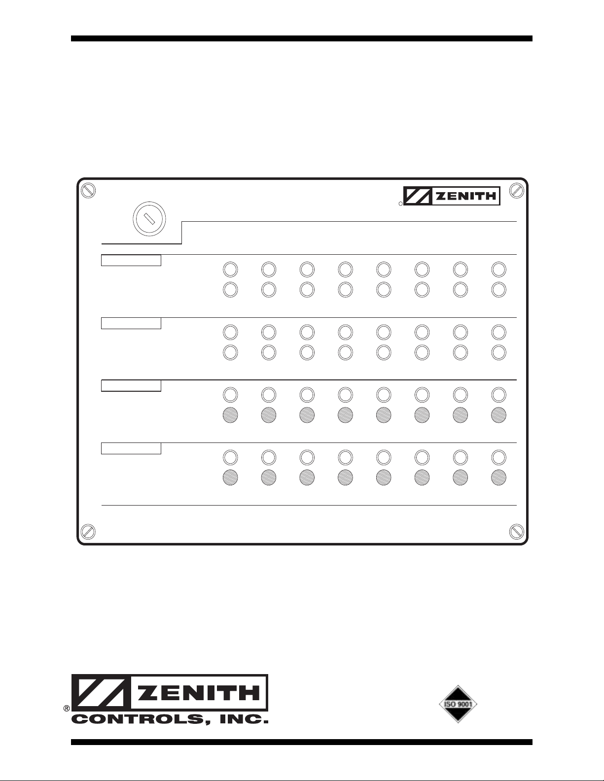
MONITOR CONTROL
POSITION
NORMAL
EMERGENCY
SOURCE
NORMAL
EMERGENCY
TIME DELAY
BYPASS
TEST
IN PROGRESS
INITIATE
(HOLD UNTIL TRANSFER OCCURS)
AUTOMATIC TRANSFER SWITCH
ANNUNCIATOR
ACTIVE
R
CONTROLS, INC.
12345678
Page 2

Page
Overview and Features . . . . . . . . . . . . . . . . . . . . . . . . . . . . . . . . . . . . . . . . . . . . . . . . . . . . . . . . . . . . . . . . . . . . . . . . . . . . .5-1
Installation
. . . . . . . . . . . . . . . . . . . . . . . . . . . . . . . . . . . . . . . . . . . . . . . . . . . . . . . . . . . . . . . . . . . . . . . . . . . . . . . . . . . . . . . . . . . 5-2
ZNET900(A/B) Annunciator
. . . . . . . . . . . . . . . . . . . . . . . . . . . . . . . . . . . . . . . . . . . . . . . . . . . . . . . . . . . . . . . . . .5-2
ZNET901 Expansion Unit for Annunciation
. . . . . . . . . . . . . . . . . . . . . . . . . . . . . . . . . . . . . . . . . . . . . . .5-3
Topology
. . . . . . . . . . . . . . . . . . . . . . . . . . . . . . . . . . . . . . . . . . . . . . . . . . . . . . . . . . . . . . . . . . . . . . . . . . . . . . . . . . . . . . . . . . . . . . .5-4
Singly Terminated Network (Daisy Chain)
. . . . . . . . . . . . . . . . . . . . . . . . . . . . . . . . . . . . . . . . . . . . . . . . . .
5-4
Doubly Terminated Network (Backbone with Drops)
. . . . . . . . . . . . . . . . . . . . . . . . . . . . . . . . . . . . .5-4
User Settings
. . . . . . . . . . . . . . . . . . . . . . . . . . . . . . . . . . . . . . . . . . . . . . . . . . . . . . . . . . . . . . . . . . . . . . . . . . . . . . . . . . . . . . . . .5-6
Dip Switch Designations
. . . . . . . . . . . . . . . . . . . . . . . . . . . . . . . . . . . . . . . . . . . . . . . . . . . . . . . . . . . . . . . . . . . . . . .5-6
Maintenance and Testing
. . . . . . . . . . . . . . . . . . . . . . . . . . . . . . . . . . . . . . . . . . . . . . . . . . . . . . . . . . . . . . . . . . . . . . . . . . 5-7
Troubleshooting
. . . . . . . . . . . . . . . . . . . . . . . . . . . . . . . . . . . . . . . . . . . . . . . . . . . . . . . . . . . . . . . . . . . . . . . . . . . . . . . . .5-7
Table of Contents
Page 3
■■
Zenith Controls, Inc. ZNET900A, ZNET900B and ZNET901 Operation and Maintenance Manual (18R-1000) 1
■■
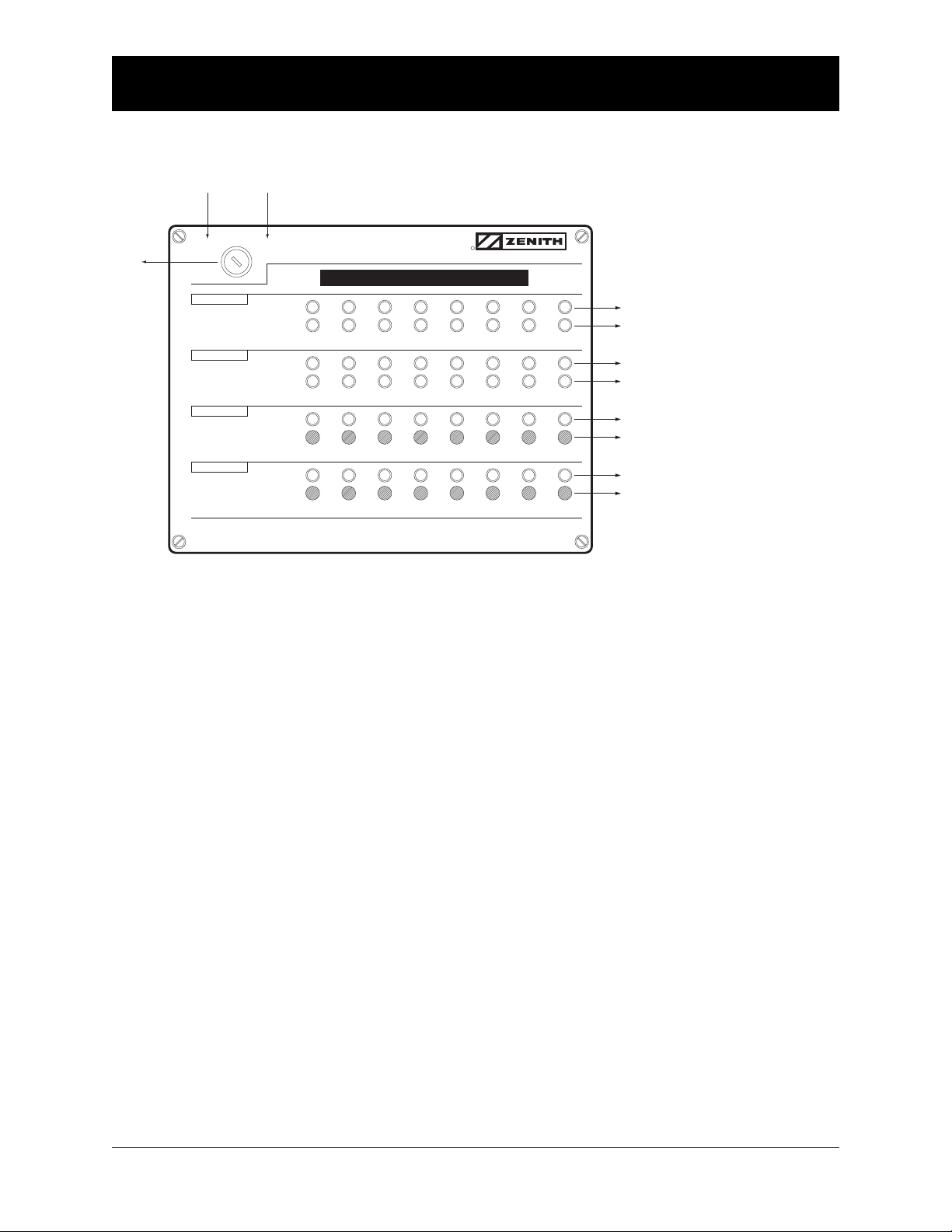
Overview and Features
KEY SWITCH —
The MONITOR position allows operation of LEDs only. (Key can be removed in this position) The CONTROL
position allows operation of LEDs and the pushbuttons. (Key cannot be removed in this position)
POSITION — Normal LED (Green)
Indicates that the corresponding Transfer Switch load is connected to the Normal source.
POSITION — Emergency LED (Red)
Indicates that the corresponding Transfer Switch load is connected to the Emergency source.
SOURCE — Normal LED (Green)
Indicates that the corresponding Transfer Switch has an acceptable Normal source.
SOURCE — Emergency LED (Red)
Indicates that the corresponding Transfer Switch has an acceptable Emergency source.
TIME DELAY — Active LED (Yellow)
This flashing LED indicates that the corresponding Transfer Switch has a timer functioning. Timers monitored includes
all timers associated with delaying transfer in either direction. Note: Not available in closed transition mode.
TIME DELAY — Bypass Push Button
Will instantaneously lapse T or W timer whichever is timing concurrent with pushbutton activation. (Key Switch
must be in the Control position) Note: Not available in closed transition mode.
TEST — In Progress LED (Yellow)
Indicates the corresponding Transfer Switch is in a test mode. Indication will occur whether the test is initiated
at the annunciator or locally at the ATS.
TEST — Initiate Push Button
Begins a test sequence (power loss simulation) but must be held until transfer occurs. Transfer is complete
once the Emergency Position and Emergency Source LEDs are both illuminated. Releasing before test
is complete will cancel the test. (Key Switch must be in the Control position)
Control
Enables
Pushbuttons
POSITION
SOURCE
TEST
(HOLD UNTIL TRANSFER OCCURS)
NORMAL
EMERGENCY
NORMAL
EMERGENCY
ACTIVE
BYPASS
IN PROGRESS
INITIATE
(Key Removable Only in MONITOR Position)
AUTOMATIC TRANSFER SWITCH
ANNUNCIATOR
Customer Field Designation Label
12345678
R
CONTROLS, INC.
Green LED ..................... Normal Position
Red LED ........................Emergency Position
Green LED ..................... Normal Source
Red LED ........................Emergency Source
Yellow LED ....................Active Time Delay
Black Push Button ........Bypass Time Delay (T or W)
Yellow LED ....................In Progress Test
Black Push Button ........Initiate Test
Key
Switch
Monitor
LEDs Only
MONITOR CONTROL
TIME DELAY
Page 4

Installation
ZNET900(A/B) Annunciator
1. Remove cover panel (see Figure below).
2. Mount unit to wall.
3. Connect network connection as shown.
4. Connect power input as shown.
5. Reinstall cover.
■■
2 ZNET900A, ZNET900B and ZNET901 Operation and Maintenance Manual (18R-1000) Zenith Controls, Inc.
■■
* Adapters Available - Contact Factory
ZNET901
EXTENSION
CONNECTIONS
(SEE PAGE 3)
D-IN
COM
COM
+5V
CLOCK
DATA
SERIAL
PRINTER
PORT
SW1
D-IN
COM
COM
+5V
CLOCK
DATA
SERIAL
PRINTER
PORT
SW1
DIP
SWITCH
SERVICE SWITCH
24V
AC/DC
USE
BELDEN
8471
POWER LED
SERVICE LED
SERVICE SWITCH
24V
AC/DC
USE
NETWORK
BELDEN
8471
NETWORK
POWER LED
SERVICE LED
GROUND
POWER
POWER
NETWORK
NETWORK
GROUND
POWER
POWER
CUSTOMER SUPPLIED *
24V AC or DC INPUT
(40 VA REQUIRED)
Page 5

Installation (cont’d)
ZNET901 Extension Unit for Annunciator
1. Remove cover panel (see Figure below).
2. Mount extension unit no further than 2' - 0" (two feet) from ZNET900(A/B).
3. Connect extension unit to ZNET900(A/B) by wiring the 4 wires to the slots
designated for COM, 5VDC, clock and data. Be sure to match the wire colors.
4. Reinstall cover.
NOTE: Extension unit does not require network or power connections.
■■
Zenith Controls, Inc. ZNET900A, ZNET900B and ZNET901 Operation and Maintenance Manual (18R-1000) 3
■■
ANNUNCIATOR PCB’s
#14
J2
J2
SW3
#13
J2
J2
SW3
#12
J2
J2
SW3
#11
J2
J2
SW3
#10
J2
J2
SW3
#9
J2
J2
SW3
Black
Red
White
Green
COM
+5V
Clock
Data
CONNECT TO
ZNET900(A/B)
(SEE PAGE 2)
Page 6

■■
4 ZNET900A, ZNET900B and ZNET901 Operation and Maintenance Manual (18R-1000) Zenith Controls, Inc.
■■
Topology
Singly Terminated Network (Daisy Chain)
Doubly Terminated Network (Backbone with Drops)
N
E
8
D
L
E
0
F
1
T
3
,
.
1
O
(
M
0
0
4
.
X
A
M
R
1
/
4
M
I
L
E
)
B
MAXIMUM TOTAL NETWORK CABLE LENGTH: 500 M (1,640 FT.)
TWO RESISTORS PROVIDED WITH ANNUNCIATOR
*
105
É
TWO
RESISTORS
4
7
1
REQUIRED
WIRED
PARALLEL
*
É
*
105
MAX. 3 M
(10 FT.) DROP
MAXIMUM TOTAL LENGTH: 2,700 M (8,850 FT. OR 1.7 MILES)
TWO RESISTORS PROVIDED WITH ANNUNCIATOR
*
BELDEN 8471
105
É
*
Page 7

User Settings
DIP Switch Designations
NOTE: This setting is necessary only if optional printer is used.
Entry of the time and date values for the clock/calendar are entered via the 8-position
DIP switch SW1 (see Page 2). The service push button switch is used to trigger the data
entry. The sequence of operations is as follows:
1. Record the current settings of the DIP switches.
2. Set switches 8 thru 4 OFF and 3 thru 1 ON. Press the service switch. The printer
will print the message “Start clock-calendar set.”
3. Set switches 3 thru 1 according to the following table to set different fields. Switches 8
thru 4 are set to the value of the field in binary code. Press the service switch. The
printer will print a message with the field name and the value. It is only necessary
to set those fields which need to be changed.
High digit of the Year (0-9)
SW3
OFF
SW2
ON
SW1
ON
Low digit of the Year (0-9) ON
OFF
ON
Month (01-12) OFF
OFF
ON
Date (01-31) ON
ON
OFF
Hour (00-24) OFF
ON
OFF
High digit of the Minute (0-5) ON
OFF
OFF
Low digit of the Minute (0-9) OFF
OFF
OFF
8 7 6 5 4 3 2 1
ON
OFF
■■
Zenith Controls, Inc. ZNET900A, ZNET900B and ZNET901 Operation and Maintenance Manual (18R-1000) 5
■■
Page 8

DIP Switch Designations (cont’d)
User Settings (cont’d)
0
SW8
OFF
SW7
OFF
SW6
OFF
1 ON
OFF
OFF
2 OFF
ON
OFF
4 OFF
OFF
ON
5 ON
OFF
ON
6 OFF
ON
ON
7 ON
ON
ON
SW5
OFF
OFF
OFF
OFF
OFF
OFF
OFF
SW4
OFF
OFF
OFF
3 ON
ON
OFF OFF OFF
OFF
OFF
OFF
OFF
8 OFF
OFF
OFF ON OFF
9 ON
OFF
OFF ON OFF
10 OFF
ON
OFF ON OFF
11 ON
ON
OFF ON OFF
12 OFF
OFF
ON ON OFF
13 ON
OFF
ON ON OFF
14 OFF
ON
ON ON OFF
15 ON
ON
ON ON OFF
16 OFF
OFF
OFF OFF ON
17 ON
OFF
OFF OFF ON
18 OFF
ON
OFF OFF ON
19 ON
ON
OFF OFF ON
20 OFF
OFF
ON OFF ON
21 ON
OFF
ON OFF ON
22 OFF
ON
ON OFF ON
23 ON
ON
ON OFF ON
24 OFF
OFF
OFF ON ON
25 ON
OFF
OFF ON ON
26 OFF
ON
OFF ON ON
27 ON
ON
OFF ON ON
28 OFF
OFF
ON ON ON
29 ON
OFF
ON ON ON
30 OFF
ON
ON ON ON
31 ON
ON
ON ON ON
The setting of the switches 8 thru
4 for different values shown on
the right:
4. Set switches 8 thru 4 OFF
and 3 thru 1 ON. Press
the service switch. The
entered values are loaded
into the real-time clock/
calendar. The printer will
print the message “End
clock/calendar set.”
5. Restore DIP switches
to the original settings
recorded in the first step.
NOTE: The DIP switches (switch 4
through switch 8) are also used
to set the annunciator ID which
printed out in the event log in
all the messages. The ID values
(0 through 31) are set as indicated
in the table on the right. The ID
value is read only upon power up
of the unit and therefore changing
the DIP switch settings during
the clock/calendar setting does not
affect the ID number. However,
the switches should be returned
to their original settings after completing the clock/calendar set procedure so that the original ID setting is not affected.
■■
6 ZNET900A, ZNET900B and ZNET901 Operation and Maintenance Manual (18R-1000) Zenith Controls, Inc.
■■
Page 9

Maintenance and Testing
Troubleshooting
None of the the LEDs will illuminate:
1. Check power supply for proper connection to annunciator unit. (Power
LED inside unit will be illuminated
if power supply is connected properly).
See Page 1.
Some of the LEDs not illuminating:
1. Are there less units on the network
than there are available slots?
2. Are network terminations on
remote ATS units connected?
3. Do all ATS units have power?
4. Do all ATS units have installed
network interface cards?
The position and source availability LEDs
flash on and off:
1. This indicates that network connections are open between annunciator
and corresponding ATS.
2. Are there less units on the network
than there are available slots?
3. Are network terminations on
remote ATS units connected?
4. Do all ATS units have power?
5. Do all ATS units have network
interface cards installed and network cable connected?
■■
Zenith Controls, Inc. ZNET900A, ZNET900B and ZNET901 Operation and Maintenance Manual (18R-1000) 7
■■
MONITOR CONTROL
POSITION
EMERGENCY
SOURCE
EMERGENCY
TIME DELAY
TEST
IN PROGRESS
(HOLD UNTIL TRANSFER OCCURS)
MONITOR CONTROL
POSITION
EMERGENCY
SOURCE
EMERGENCY
TIME DELAY
TEST
IN PROGRESS
(HOLD UNTIL TRANSFER OCCURS)
AUTOMATIC TRANSFER SWITCH
ANNUNCIATOR
NORMAL
NORMAL
ACTIVE
BYPASS
INITIATE
12345678
AUTOMATIC TRANSFER SWITCH
ANNUNCIATOR
NORMAL
NORMAL
ACTIVE
BYPASS
INITIATE
12345678
R
CONTROLS, INC.
R
CONTROLS, INC.
MONITOR CONTROL
AUTOMATIC TRANSFER SWITCH
ANNUNCIATOR
R
CONTROLS, INC.
POSITION
SOURCE
TIME DELAY
TEST
(HOLD UNTIL TRANSFER OCCURS)
NORMAL
EMERGENCY
NORMAL
EMERGENCY
ACTIVE
BYPASS
IN PROGRESS
INITIATE
12345678
Page 10

© 1998 Zenith Controls, Inc.
830 West 40thStreet
Chicago, IL 60609 USA
Phone: 773 247-6400
Fax: 773 247-7805
www.zenithcontrols.com
E-Mail: zenith@zenithcontrols.com
 Loading...