

Page 1
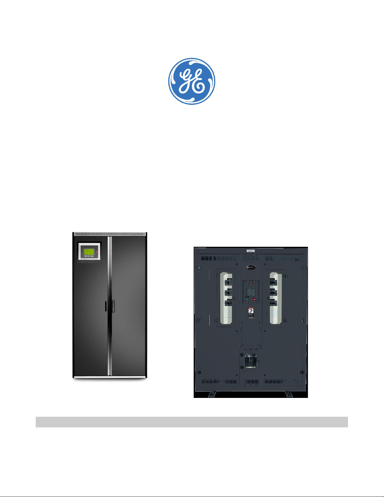
GE ZENITH™ SERIES MDU
MONITORED DISTRIBUTION UNIT
50KVA – 750KVA
OWNER’S MANUAL
(01/2013)
Page 2

Table of Contents
Table of Contents
TABLE OF CONTENTS.........................................................................................................................................................2
1.0 INTRODUCTION............................................................................................................................................................4
2.0 RECEIVING YOUR MDU ................................................................................................................................................5
2.1. RECEIVING AND UNPACKING INSTRUCTIONS........................................................................................................................5
2.2. INSPECTION PROCEDURES ................................................................................................................................................6
3.0 INSTALLATION PROCEDURES .....................................................................................................................................7
3.1. EQUIPMENT PLACEMENT...................................................................................................................................................7
3.1.1. Clearances..........................................................................................................................................................7
3.1.2. Raised Floor........................................................................................................................................................8
3.1.3. Cabling ...............................................................................................................................................................8
3.1.4. Cabinet Leveling.................................................................................................................................................8
3.1.5. Raised floor loading...........................................................................................................................................8
3.1.6. Raised floor cable entry .....................................................................................................................................8
3.2. SYSTEM GROUNDING RECOMMENDATIONS .........................................................................................................................9
3.2.1. Power System Grounding..................................................................................................................................9
3.2.2. Grounding Conductors ......................................................................................................................................9
3.3. INTERNAL WIRE SIZING..................................................................................................................................................12
3.4. HIGH FREQUENCY (RF) GROUNDING (COMPUTER ROOMS) ...................................................................................................13
3.5. INPUT POWER JUNCTION BOX AND CABLE ASSEMBLY (OPTIONAL)........................................................................................13
3.6. TORQUE SPECIFICATIONS ...............................................................................................................................................14
3.6.1. Structural Fasteners.........................................................................................................................................14
3.6.2. MCCB’s, MCSW’s, Contactors, and Other Electrical Components ..................................................................14
3.7. TORQUE VALUE QUICK REFERENCE..................................................................................................................................14
3.7.1. Standard Circuit Breakers (Mains & Sub-feeds) ..............................................................................................14
3.7.2. Transformer Lugs.............................................................................................................................................15
3.7.3. Fasteners..........................................................................................................................................................15
3.7.4. Terminal Blocks and Distribution Breakers.....................................................................................................15
3.7.5. Junction Box and Power Cable Sizing Chart ..................................................................................................16
3.7.6. System Power-Up Procedure ..........................................................................................................................17
3.8. CUSTOMER CONNECTIONS: LOW VOLTAGE INTERFACE BOARD.............................................................................................18
3.8.1. GE Zenith Series Monitoring Package .............................................................................................................18
3.8.2. M4 Monitoring Package...................................................................................................................................19
3.8.3. Optional Low Voltage Junction Box................................................................................................................21
3.8.4. Output Distribution Cable(s) Installation .........................................................................................................21
4.0 SYSTEM MONITORING ...............................................................................................................................................23
4.1. GE ZENITH SERIES MDU MONITOR .................................................................................................................................23
4.1.1. LCD Monitor Layout .........................................................................................................................................23
4.1.2. GE Zenith Series Monitor Features ..................................................................................................................24
4.1.3. Control Functions.............................................................................................................................................26
4.1.4. Monitor Screens ...............................................................................................................................................27
4.1.5. Contractor Connections...................................................................................................................................30
4.1.6. Communications..............................................................................................................................................30
5.0 BRANCH CIRCUIT MONITORING SYSTEM (BCMS)....................................................................................................33
5.1. BCMS COMPONENTS....................................................................................................................................................33
5.1.1. Acquisition Module...........................................................................................................................................33
5.1.2. Current Transformers (Panel board CT’s) ........................................................................................................34
GE ZENITH CONTROLS MDU Owner’s Manual
601 SHILOH ROAD January 2013
Plano, TX 75074 Page 2
Page 3

Table of Contents
5.1.3. Current Transformers (CT’s) .............................................................................................................................34
5.2. BCMS LOCAL MONITORING VIA GE ZENITH SERIES MDU MONITOR ....................................................................................35
5.2.1. BCMS Device Setup..........................................................................................................................................35
5.2.2. Panel board Information .................................................................................................................................36
6.0 SYSTEM TROUBLESHOOTING ....................................................................................................................................39
6.1. SYSTEM SAFETY PRECAUTIONS........................................................................................................................................39
6.1.1. Troubleshooting guidelines (GE Zenith Series Monitoring Package)..............................................................39
7.0 GE ZENITH SERIES MONITOR ALARM DESCRIPTION ..............................................................................................40
8.0 SPECIAL INSTRUCTIONS ............................................................................................................................................42
8.1. OUTPUT PANEL BOARDS.................................................................................................................................................42
8.1.1. Panel board manufacturers ............................................................................................................................42
8.2. OUTPUT DEDICATED CIRCUIT BREAKERS (SUB-FEEDS) ........................................................................................................43
8.3. LOW VOLTAGE INTERFACE BOARD (CONTRACTOR BOARD)...................................................................................................43
9.0 WARRANTY, MAINTENANCE AND TERMS ................................................................................................................44
9.1. GE SERVICE DEPARTMENT..............................................................................................................................................44
9.1.1. GE’s Standard Warranty..................................................................................................................................44
9.1.2. Start Up ............................................................................................................................................................44
9.1.3. Maintenance Contracts ...................................................................................................................................44
9.1.4. Time and Materials ..........................................................................................................................................44
9.2. GE MAINTENANCE CONTRACTS.......................................................................................................................................45
9.2.1. Features & Benefits..........................................................................................................................................45
10.3 WARRANTY VALIDATION REQUEST...................................................................................................................................46
9.4. WARRANTY AGREEMENT ................................................................................................................................................47
10.0 APPENDICES ...............................................................................................................................................................48
10.1. APPENDIX A – MDU INPUT BREAKER SIZING CHART ......................................................................................................48
10.2. APPENDIX B - CLASS A COMPUTING DEVICE: INFORMATION TO USER ..............................................................................49
11.0 SPARE PARTS ..............................................................................................................................................................50
11.1. SPARE PARTS KITS - GE ZENITH MDU WITH M4 MONITORING PACKAGE..........................................................................51
11.2. SPARE PARTS KITS - GE ZENITH MDU WITH GE ZENITH SERIES MONITORING PACKAGE .....................................................51
11.2.1. GE Zenith Series MDU - “Option A” Kit.............................................................................................................51
11.2.2. GE Zenith Series MDU - “Option B” Kit.............................................................................................................51
11.2.3. GE Zenith Series MDU w/ BCMS - “Option C” Kit.............................................................................................51
12.0 DRAWINGS..................................................................................................................................................................52
12.1. TYPICAL OUTLINE, 30KVA-150KVA MDU ..................................................................................................................53
12.2. TYPICAL OUTLINE, 200KVA-300KVA MDU ................................................................................................................54
12.3. TYPICAL OUTLINE, 400KVA – 750KVA MDU ..............................................................................................................55
12.4. TYPICAL 30KVA–300KVA MDU FLOOR STAND (11”–76” HEIGHTS)...............................................................................56
12.5. TYPICAL 400KVA–750KVA MDU FLOOR STAND (60” HEIGHT SHOWN)..........................................................................57
13.0 NOTES..........................................................................................................................................................................58
GE ZENITH CONTROLS MDU Owner’s Manual
601 SHILOH ROAD January 2013
Plano, TX 75074 Page 3
Page 4

1.0 Introduction
GE Zenith Controls, (GE) designs and manufactures the finest power distribution products available on the
market today. GE’s Monitored Distribution Units (MDUs) are completely self-contained, factory-tested units
designed primarily for power conditioning, voltage transformation, isolation, over-current protection,
distribution, static transfer switching and monitoring of AC power for computers and other equipment
sensitive to power quality.
Your MDU is carefully assembled by craftsmen from parts manufactured to exact specifications from the
highest quality materials. Only the optional input power junction box requires field installation.
GE MDU’s are designed to be an integral part of your power quality solution, while allowing for easy expansion
and relocation of your system capacity requirements.
This manual includes user operation and installation information for the GE Zenith - Series Monitored
Distribution Unit with GE’s GE Zenith Series monitoring package or M4 monitoring system
If you require additional information or need technical assistance please contact GE’s field support division at
any time.
Introduction
GE ZENITH CONTROLS, INC.
601 SHILOH ROAD
PLANO, TX 75074
(800) 637-1738
GE ZENITH CONTROLS MDU Owner’s Manual
601 SHILOH ROAD January 2013
Plano, TX 75074 Page 4
Page 5
2.0 Receiving Your MDU
2.1. Receiving and Unpacking Instructions
GE carefully packages every MDU to ensure damage-free delivery to your job site. GE recommends
the following unpacking procedures be followed upon delivery.
1. Inspect packaging, exterior panels, and doors for any visible damage (i.e. scratches dents,
cracks, or torn packaging). If any damage exists, please call the GE Service Team at (800) 637-
1738.
2. Remove the outer layer of protective shrink wrap from the unit.
3. Carefully cut the safety bands, making sure that they do not scrape the exterior of the unit or
scratch the paint. Use eye, face, and hand protections to guard against injury when bands are
cut.
4. At this point, your unit is ready to be removed from the pallet using a fork-lift truck. Use extreme
caution to ensure the unit is properly centered on the forks.
5. Once the unit is completely off the pallet and ramp, carefully remove the under layer of
protective shrink wrap.
6. Ensure that the casters both rotate and can roll freely so as not to damage the flooring.
7. The unit is now ready to be rolled into its final position and prepared for installation. Please refer
to the Installation Procedures listed on page 8 before proceeding.
8. If any further assistance is needed, please call the GE Service Team at (800) 637-1738.
Receiving Your MDU
Note: The MDUs should not be loosened from the shipping pallet until all handling by a forklift or
pallet jack is completed. Complete internal inspection should be done only after
equipment positioning and prior to electrical hookup.
Note: Any damages must be noted on the bill of laden with a detailed description of the
damages incurred. A claim will need to be filed with the freight company at the time of
delivery. Failure to properly document all damages may result in the unit’s warranty
being voided.
GE ZENITH CONTROLS MDU Owner’s Manual
601 SHILOH ROAD January 2013
Plano, TX 75074 Page 5
Page 6

2.2. Inspection Procedures
The following inspection procedures should be performed immediately after your unit has arrived.
Report any damages immediately to your GE Service Team by calling (800) 637-1738. All freight
damage claims should be initiated with the freight carrier immediately.
1. CABINET: Inspect packaging, exterior panels, and doors for any visible damage (i.e. scratches
dents, cracks, or torn packaging). If any damage is noted, please the GE Service Team at (800)
637-1738.
2. TRANSFORMER: Inspect the transformer for any loose connections or displacement during
shipment. Check to make sure all terminal lugs are tight and secure.
3. INTERNAL FEEDERS: Ensure all lug connections are tight and secure.
Check the main input feeder connections at the main breaker to be sure vibration has not
loosened the terminal screws.
Using the same procedure, check the feeders from the load side of the main breaker to
the primary side of the transformer.
Check all other lugs (i.e. neutral bus, ground bus, terminal blocks, etc.).
4. OUTPUT DISTRIBUTION CABLE ASSEMBLIES: cable coils must be inspected for cuts and/or damaged
conduits. Each cable should be uncoiled and inspected individually.
Note: Do not remove the cable shipping pallet until the unit is near its final position
5. INPUT POWER JUNCTION BOX (POWER J-BOX): carefully inspect the entire box for damage.
Receiving Your MDU
GE ZENITH CONTROLS MDU Owner’s Manual
601 SHILOH ROAD January 2013
Plano, TX 75074 Page 6
Page 7
3.0 Installation Procedures
Output
208V
Input
480V
600V
Without
w/ (1)
w/ (2)
w/ (1)
w/ (2)
The following section of your owner’s/operator’s manual covers the general requirements for the installation
of your Monitored Distribution Unit and its associated components.
Note: A GE authorized field engineer and/or a licensed electrician must install each unit. Startup by a
GE certified technician is also required to validate the warranty.
3.1. Equipment placement
The preferred location of your MDU is in the center of the room. Although this location is not
mandatory, it will allow accessibility for preventative maintenance (PM) checks and any other
required services. Follow the National Electrical Code (NEC) and local electrical codes for panel board
clearance requirements. The MDU is intended for indoor installation in an area with ambient
temperatures of 32F to 104F (OC to 40C) with a relative humidity of 0% to 95% (non-condensing).
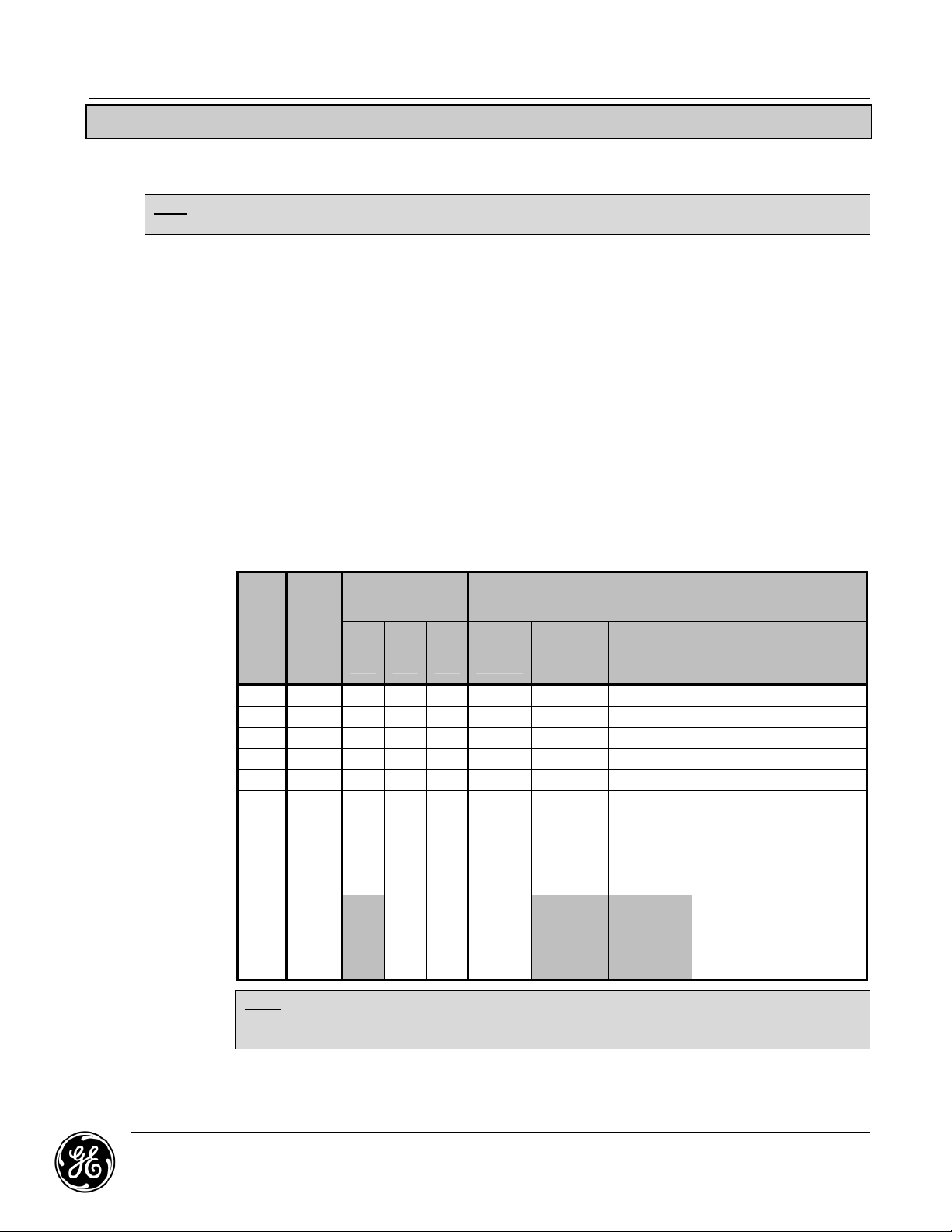
3.1.1. Clearances
Refer to the MDU shop drawings/submittals for recommended minimum service
clearances. The NEC requires the indicated front and rear clearances for service access
(see Drawings section for typical clearances). Clearance above the unit is required for
cooling airflow (exhaust). Units with optional side cars with the distribution section also
require service access clearance on the side. A MDU produces heat under normal
operation. Figure 1 shows typical MDU weights and heat generation.
Installation Procedures
Figure 1: MDU Approximate Weights and Heat Generation
MDU
Ratin
g
(kVA)
Heat
(kBTU)
Full Load
Amperage
Input
Input
Sidecar
Sidecar
MDU Weight (Lbs)
9”-
Sidecars
9”-
21”-
Sidecar
Sidecars
15 2.7 42 18 14 574 724 874 824 1074
30 4.8 83 36 29 945 1095 1245 1195 1445
50 7.1 139 60 48 1302 1452 1602 1552 1802
75 7.6 208 90 72 1470 1620 1770 1720 1970
100 8.4 278 120 96 1785 1935 2085 2035 2285
125 10.4 347 150 120 1855 2005 2155 2105 2355
150 12.2 416 180 144 1967 2117 2267 2217 2467
200 15.6 555 241 192 2149 2299 2449 2399 2649
225 17.6 625 271 217 2457 2607 2757 2707 2957
300 21.0 833 361 289 3297 3447 3597 3547 3797
400 34.6 N/A 481 384 2900 N/A N/A 3150 3400
500 43.3 N/A 601 481 3900 N/A N/A 4150 4400
625 54.1 N/A 752 602 4489 N/A N/A 4739 4989
750 64.9 N/A 903 721 5390 N/A N/A 5640 5890
21”-
Note: Weights listed are for MDU’s with k-20 transformers and no sidecars. For k-1 weight,
multiply 0.72. For k-13 weights, multiply by 1.12. Weights are for estimate purposes
only. Actual shipping weight may vary.
GE ZENITH CONTROLS MDU Owner’s Manual
601 SHILOH ROAD January 2013
Plano, TX 75074 Page 7
Page 8

3.1.2. Raised Floor
If the MDU is placed on a raised floor, it is recommended that the casters rest as close as
possible to the corners of the floor tiles. This will allow the unit to span (1) one complete
floor tile, permitting cutouts in the tile.
3.1.3. Cabling
The unit location may be specified on a floor plan which shows related equipment as well
as identifying distribution cable runs. These cable runs should be recorded on panel board
legend cards. Each legend card specifies the circuit location on the panel board and the
computer or peripheral description.
3.1.4. Cabinet Leveling
Once the MDU has been positioned in its permanent location, turn down the (2) two front
and the (2) two rear (optional) leveling pads on the base of the MDU until they make firm
contact with the floor or landing surface. Level the unit and assure that the leveling pads
are always in contact with the floor or landing surface. The primary purpose of the leveling
pads is to prevent movement of the cabinet before and during attachment of the output
cables. Casters, if provided with the MDU, will support the weight of the unit.
3.1.5. Raised floor loading
Additional floor bracing is recommended for all units. The weight of larger units should be
considered in the room design. The raised floor system must be able to support both the
MDU as well as any other associated equipment. GE recommends that the end user
properly compute raised floor loading and supply proper floor bracing when needed.
Installation Procedures
Floor stands can also be provided by GE to support the MDU’s weight on the raised floor.
Note: GE does not recommend the removal of Casters for MDU sizes up to 300kVA.
Floor stands are designed to support your MDU with casters in place. Placing
the MDU on the floor or stand without casters may damage the MDU cabinet
which may void your warranty.
For typical floor weights of the MDU, please refer to Figure 1 on the previous page, or your
submittal package.
3.1.6. Raised floor cable entry
When applicable, provisions must be made for cable entry through the raised floor once
the MDU has been properly located. The cable entry configuration should be free of any
sharp edges and designed to allow permanent access for the distribution cables and input
power cables. The tile directly in front of the unit should be easily removable for access to
these cables.
GE ZENITH CONTROLS MDU Owner’s Manual
601 SHILOH ROAD January 2013
Plano, TX 75074 Page 8
Page 9

3.2. System Grounding Recommendations
Note: Grounding for this equipment must not violate any local building or electrical codes.
System grounding has long been a topic affecting the computer equipment industry. The proper
grounding of your GE Monitored Distribution Unit is critical to the operation of the unit. Improper
grounding of a system may create unsafe conditions as well as electrical noise that may cause data
processing problems. GE has conducted a great deal of research on system grounding, and makes
the following recommendations.
3.2.1. Power System Grounding
The primary concern is to provide a safe system that both complies with the electrical code
(NEC article 250 in the USA, Canadian Electrical Code Section, 10, IEEE wiring regulations
and chapter 54 in the UK) and ensures proper and safe equipment operation. The MDU
should have a parity sized, green grounding conductor connected from the power J box to
the nearest grounding electrode. The MDU contains a factory wired, green grounding
conductor (within the power cable) from the power J box to a single ground point inside
the MDU cabinet. From this single ground point, each piece of equipment should be
separately grounded via a green grounding conductor within the flexible output computer
grade cable.
3.2.2. Grounding Conductors
An isolation grounding conductor identical in size, insulation material, and thickness to the
grounded and ungrounded branch circuit supply conductors should be installed as part of
the branch circuit that supplies the system. This grounding conductor should be marked
green (or green with yellow stripe) when using a (4) four wire system. A typical power wiring
diagram is illustrated in Figure 2.
Installation Procedures
This grounding conductor should be grounded at the nearest available grounding
electrode in accordance with all electrical codes. The output cabling receptacles of the
MDU should be the same grounding type. The grounding conductors serving these
receptacles should be terminated at the MDU ground bus.
Figure 2 provides the ground wire ratings.
Grounding for systems with Remote Panel boards:
Careful consideration should be given to the grounding of systems with remote Panel
boards. See FIPS PUB 94 or contact GE’s factory for recommendations.
GE ZENITH CONTROLS MDU Owner’s Manual
601 SHILOH ROAD January 2013
Plano, TX 75074 Page 9
Page 10
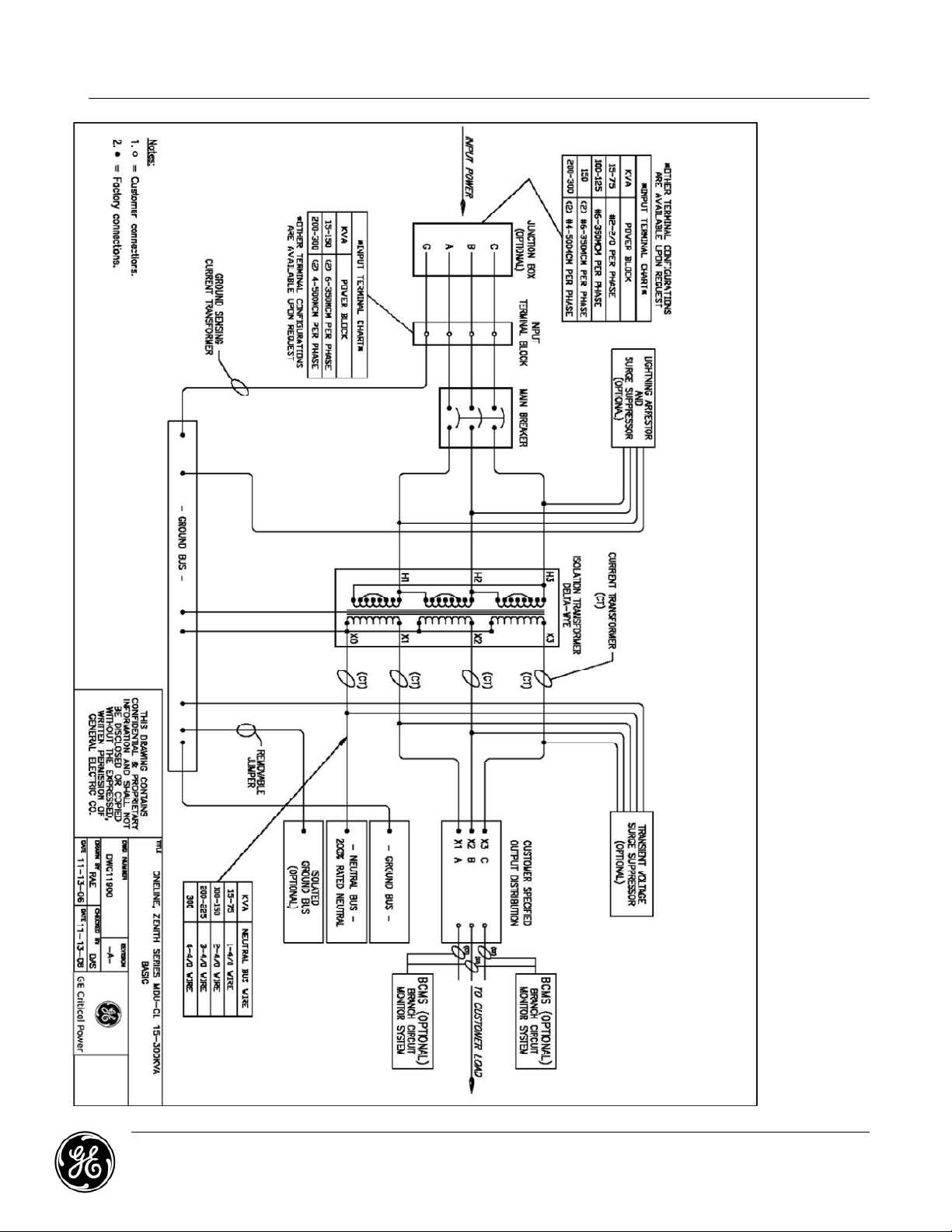
Figure 2: Typical MDU Oneline Diagram (15kVA – 300kVA)
Installation Procedures
GE ZENITH CONTROLS MDU Owner’s Manual
601 SHILOH ROAD January 2013
Plano, TX 75074 Page 10
Page 11
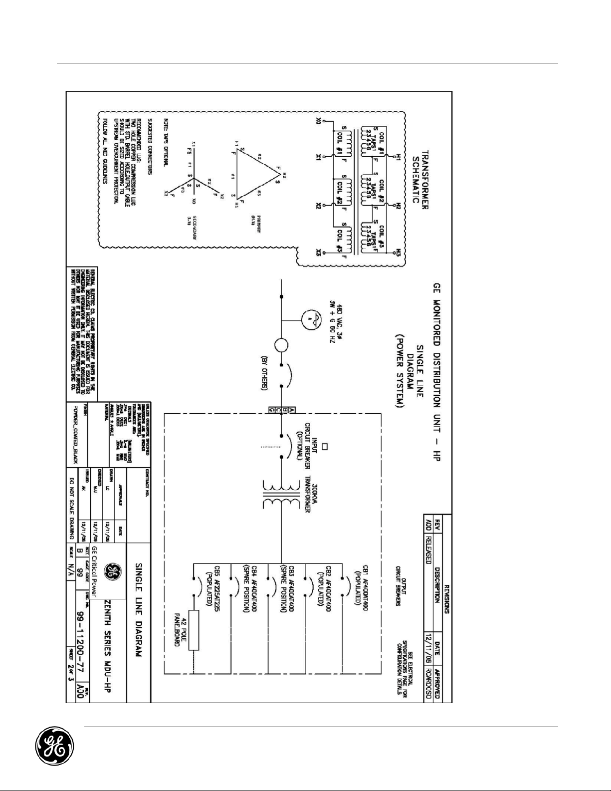
Figure 2: Typical MDU Oneline Diagram (400kVA – 750kVA)
Installation Procedures
GE ZENITH CONTROLS MDU Owner’s Manual
601 SHILOH ROAD January 2013
Plano, TX 75074 Page 11
Page 12
3.3. Internal Wire Sizing
Circuit Breaker
Installation Procedures
Protective
or Actual
Amperage
25 #10 #14 #10 #12 #10
30 #10 #12 #8 #10 #10
40 #8 #10 #8 #10 #10
50 #8 #10 #6 #10 #10
60 #8 #8 #4 #8 #10
70 #8 #8 #3 #8 #8
80 #6 #8 #3 #8 #8
90 #6 #8 #2 #6 #8
100 #4 #8 #1 #6 #8
110 #4 #8 #1 #4 #6
125 #4 #8 1/0 #4 #6
150 #2 #6 2/0 #3 #6
175 #1 #6 3/0 #2 #6
200 1/0 #4 3/0 #1 #6
225 1/0 #4 4/0 1/0 #4
250 2/0 #3 250MCM 1/0 #4
300 3/0 #2 350MCM 2/0 #4
350 4/0 #1 400MCM 3/0 #3
400 250MCM 1/0 500MCM 4/0 #3
500 350MCM 2/0 750MCM 300MCM #2
600 500MCM 3/0 1000MCM 400MCM #1
700 700MCM 4/0 1500MCM 500MCM 1/0
800 800MCM 250MCM N/A 700MCM 1/0
1000 1000MCM 350MCM N/A 1000MCM 2/0
Phase Wire,
Single
3,4
1,3,4,6
Phase Wire,
Two
Parallel
Internal Conductors
Neutral
Wire,
1,3,4,6
Single
1,3,4,6
Neutral Wire,
Two
Parallel
1,3,4,6
Ground
Wire,
Single
1,3,4,6
Notes:
1. Conductor ratings are based on NEC Table 310.17.
2. Deleted.
3. All wires must be UL listed.
4. Conductors must be separated for air circulation – not bundled
5. Parallel conductor lengths must be equal within 2% (e.g. two parallel conductors 10 feet
long must match in length within 2.4”).
6. For components like circuit breakers, the 75°C column in NEC Table 310.17 must be used.
7. For components like bus bars that allow 90°C connections, the 90°C column in NEC Table
310.17 can be used.
GE ZENITH CONTROLS MDU Owner’s Manual
601 SHILOH ROAD January 2013
Plano, TX 75074 Page 12
Page 13

Installation Procedures
3.4. High Frequency (RF) Grounding (computer rooms)
In addition to the power grounding system, a reference grounding system for high frequency noise is
desirable (with the two systems being bonded together for the same reference potential). A grid
made up of (2) two foot squares will provide an effective signal reference grounding system. The
raised floor can be utilized if it has firmly connected metal stringers providing good electrical
connections. If this type of floor is not available, a grid can be fabricated by laying a mesh (2 foot
square) of braided copper strap directly on the concrete sub floor (electrically connected at each
intersection point). The frames of all the data processing equipment, including the MDU, should be
connected (by the shortest possible distance) to the reference grid with braided copper. Finally, the
reference grid should be bonded to the MDU for a single point potential ground reference.
For optimum performance all distances for power and high frequency grounding should be kept to
an absolute minimum. To summarize, a radial grounding of this type (utilizing a single ground point)
will ensure that your facility is electrically safe, complies with all code requirements, and will be
essentially free of ground caused computer noise and problems.
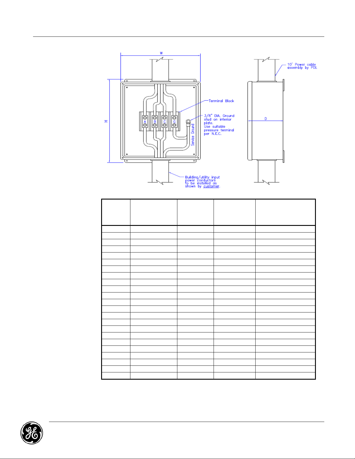
3.5. Input Power Junction Box and Cable Assembly (Optional)
Warning: Verify that incoming high voltage circuits are not energized before making any
connections in the input junction box.
If the MDU is equipped with an input junction box, then the input junction box (power J box) and
power cable assembly must be installed in accordance with all applicable electrical codes. The
power J box should be installed only by a qualified electrical contractor.
The location of the power J box in relation to the MDU is a critical relationship. The power J box must
be located within (6) six feet of the MDU. It must be positioned so as to allow accessibility after the
MDU has been installed. Extreme care should be taken so as not to restrict the positioning of any
power cabling. If the MDU is positioned with its rear panel up against a wall, the power J box must
be installed at least 36 inches (3 feet) from the wall and in a position that will allow future
accessibility. Do not obstruct the floor tiles located directly above the power J box.
It is recommended that the power J box location allows the input power cables to enter the unit
through the floor tile cutouts.
If a junction box is not furnished, the input power feeder should be connected to the main input
landings internal to the MDU.
GE ZENITH CONTROLS MDU Owner’s Manual
601 SHILOH ROAD January 2013
Plano, TX 75074 Page 13
Page 14
3.6. Torque Specifications
3.6.1. Structural Fasteners
Structural fasteners are typically used for fastening the MDU to a supplied floor stand or
concrete slab. If structural fasteners are required per assembly instructions, refer to the
table below for typical torque values. Tighten steel hardware parts (except electrical
connections) to the values given in the following table.
Bolt Diameter Tightening Torque (in-lb)
#8 (5/32”) 15
#10 (3/16”) 20
3.6.2. MCCB’s, MCSW’s, Contactors, and Other Electrical Components
Always tighten electrical component (CBs, contactors, etc.) connections to the
manufacturer’s torque specifications furnished with the component. There are some
guidelines for electrical components if no manufacturer data is available. Tighten
connections using Belleville type (spring) washers until washers are flat.
Installation Procedures
1/4” 120
5/16” 228
3/8” 396
7/16” 648
1/2” 936
3.7. Torque Value Quick Reference
Use the following as a reference only. Always check the breaker or component labeling and/or
instructions for proper torque values. DO NOT OVER TORQUE!
Always use the manufacturer’s hardware on CBs, contactors, etc. Once connections are torqued and
sealed, make sure that removable lug covers are reinstalled,
3.7.1. Standard Circuit Breakers (Mains & Sub-feeds)
Manufacturer Breaker Frame / Bolt Required Torque (ft-lb)
Square D
Cutler Hammer
ABB ISOMAX
Rear Lug Mounting Bolt
requires
Rear Lug Mounting Bolt 9.2
F Frame 6.7
K Frame 20.9
L Frame 31.3
M Frame 25.0
F Frame 10.0
J Frame 22.9
K Frame 22.9 (Wire Smaller than 250 MCM)
K Frame 31.3 (Wire 250 MCM or larger)
S3 22.9
S4 22.9
S5 22.9
GE ZENITH CONTROLS MDU Owner’s Manual
601 SHILOH ROAD January 2013
Plano, TX 75074 Page 14
Page 15

3.7.2. Transformer Lugs
1/8”4535
5/32”
100
80
3/16”
120
100
7/32”
150
120¼”200
150
5/16”
275
225
3/8”
375
300½”500
400
9/16”
600
500
Wire Size (Awg or MCM) Required Torque (ft-lb)
3.7.3. Fasteners
Installation Procedures
2/0 4.2
250 22.9
350 31.3
500 31.3
Wire Size
installed,
AWG or
MCM
SLOTTED HEAD SCREWDRIVER TORQUE VALUE (in-lb)
Slot width up to 3/64”
Slot length up to ¼”
Slot width over 3/64”
Slot length over ¼”
SCREW CONNECTOR
TORQUE VALUE (in-
#14 15 in-lb 25 in-lb
#12 15 in-lb 25 in-lb
#10 15 in-lb 25 in-lb
#8 20 in-lb 25 in-lb
#6 25 in-lb 35 in-lb
#4 N/A 35 in-lb
#3 N/A 40 in-lb N/A
#2 N/A 40 in-lb
#1 N/A 40 in-lb
1/0 N/A 40 in-lb
2/0 N/A 40 in-lb
3/0 N/A 40 in-lb N/A
4/0 N/A 40 in-lb N/A
Hex Socket Size
SOCKET HEAD SCREW CONNECTOR
TORQUE VALUE (in-lb)
HEX SOCKET ALLEN SCREW
TORQUE VALUE (in-lb)
lb)
35
35
35
40
45
45
50
50
50
50
3.7.4. Terminal Blocks and Distribution Breakers
Torque ratings vary depending on item in use. Please refer to label on the item.
3.0 ft-lb of torque is typically required for Distribution Breakers. There is a wide variation of
torque requirements for terminal blocks with various sizes.
GE ZENITH CONTROLS MDU Owner’s Manual
601 SHILOH ROAD January 2013
Plano, TX 75074 Page 15
Page 16
3.7.5. Junction Box and Power Cable Sizing Chart
Main Input
Size (Amps)
Input Power Cable
(#-Size)
Input Power
(#-Size)
Installation Procedures
Circuit
Breaker
25 1 - 8 AWG 1 - 1" 12" x 10" x 5" 4 Pole - # 12 - 2/0
30 1 - 6 AWG 1 - 1" 12" x 10" x 5" 4 Pole - # 12 - 2/0
40 1 - 6 AWG 1 - 1" 12" x 10" x 5" 4 Pole - # 12 - 2/0
50 1 - 6 AWG 1 - 1" 12" x 10" x 5" 4 Pole - # 12 - 2/0
60 1 - 6 AWG 1 - 1" 12" x 10" x 5" 4 Pole - # 12 - 2/0
70 1 - 4 AWG 1 - 1 1/4" 12" x 10" x 5" 4 Pole - # 12 - 2/0
80 1 - 4 AWG 1 - 1 1/4" 12" x 10" x 5" 4 Pole - # 12 - 2/0
90 1 - 3 AWG 1 - 1 1/4" 12" x 10" x 5" 4 Pole - # 12 - 2/0
100 1 - 3 AWG 1 - 1 1/4" 12" x 10" x 5" 4 Pole - # 12 - 2/0
110 1 - 2 AWG 1 - 1 1/4" 12" x 10" x 5" 4 Pole - # 12 - 2/0
125 1 - 1 AWG 1 - 1 1/2" 12" x 10" x 5" 4 Pole - # 12 - 2/0
150 1 - 1/0 AWG 1 - 1 1/2" 12" x 10" x 5" 4 Pole - # 12 - 2/0
175 1 - 2/0 AWG 1 - 2" 16" x 14" x 6" 4 Pole - # 6 - 350 MCM
200 1 - 3/0 AWG 1 - 2" 16" x 14" x 6" 4 Pole - # 6 - 350 MCM
225 1 - 4/0 AWG 1 - 2" 16" x 14" x 6" 4 Pole - # 6 - 350 MCM
250 1 - 250 MCM AWG 1 - 2 1/2" 24" x 18" x 6" 4 Pole - # 6 - 350 MCM
300 2 - 3/0 AWG 1 - 3" 24" x 18" x 6" 4 Pole - # 6 - 350 MCM
350 2 - 4/0 AWG 2 - 2" 24" x 18" x 6" 4 Pole - # 4 - 500 MCM
400 2 - 4/0 AWG 2 - 2" 24" x 18" x 6" 4 Pole - #4 - 500 MCM
500 2 - 250 MCM AWG 2 - 2 1/2" 24" x 18" x 6" 4 Pole - #4 - 500 MCM
600 2 - 350 MCM AWG 2 - 3" 24" x 18" x 6" 4 Pole - #4 - 500 MCM
700 2 - 500 MCM AWG 2 - 3" 24" x 18" x 6" 4 Pole - #4 - 500 MCM
800 3 - 300 MCM AWG 3 - 2 1/2" Special Special
Wire Size Per
Phase & Ground
Cable
Conduit Size
Input Junction
Box Size
(H x W x D)
Input Junction Box
Terminal Block Size
(# Poles - Wire Range)
GE ZENITH CONTROLS MDU Owner’s Manual
601 SHILOH ROAD January 2013
Plano, TX 75074 Page 16
Page 17

3.7.6. System Power-Up Procedure
Note: Before applying utility power to the unit, the electrician performing the
installation and/or a factory authorized representative should be present to
verify that the following steps have been performed properly.
1. Confirm that the MDU’s main input circuit breaker is in the “off” position.
2. Ensure that all of the MDU’s output circuit breakers or sub-feed breakers are in the “off
“position.
3. The installing contractor should now verify that the input voltage to the unit matches
the input voltage rating of the unit as identified on the system’s legend label found on
the interior of the front door. The input voltage rating also appears on the transformer
label located on the top of the high isolation transformer positioned at the rear of the
unit.
4. Ensure that the power J box has been installed correctly (i.e. proper phase rotation and
safe grounding practices as indicated above).
Warning: Ensure that the above conditions are met before applying incoming power to
the MDU.
5. Apply Power to the unit
6. Measure for the proper MDU input voltage. This should match the units rating (+ 5% to
-10% from nominal rating).
7. Check the phase rotation (clockwise) and voltage at the power J box.
8. Check to ensure the emergency power off (EPO) light is on.
Installation Procedures
9. Energize the MDU main breaker by setting the toggle to the “on” position.
Note: If the main breaker trips to the “off” position when energized, contact GE ’s
service division at (800)637-1738 as this is an indication of a fault in the unit.
10. Perform an EPO check by depressing the EPO button and assuring that the main
breaker shunt trips.
11. Manually reset the main breaker to the “on” position. This may require that you
manually trip the lever all the way to the “off” position.
12. Check the output voltages. If the output voltages are not within acceptable limits, it
may require the taps on the transformer be changed. Each transformer is labeled with
the tap connections. All tap changes must be done with the input power turned off.
13. The MDU is now ready to sequentially energize the branch circuit breakers.
14. Units equipped with monitoring can be activated by depressing the monitor on/off
button located to the left of the LCD display. See System Monitoring on page 23 of this
manual for monitor operation.
Note: Equipment attached to the MDU may require special start up procedures. Please
consult the individual manufacturers for these requirements.
GE ZENITH CONTROLS MDU Owner’s Manual
601 SHILOH ROAD January 2013
Plano, TX 75074 Page 17
Page 18
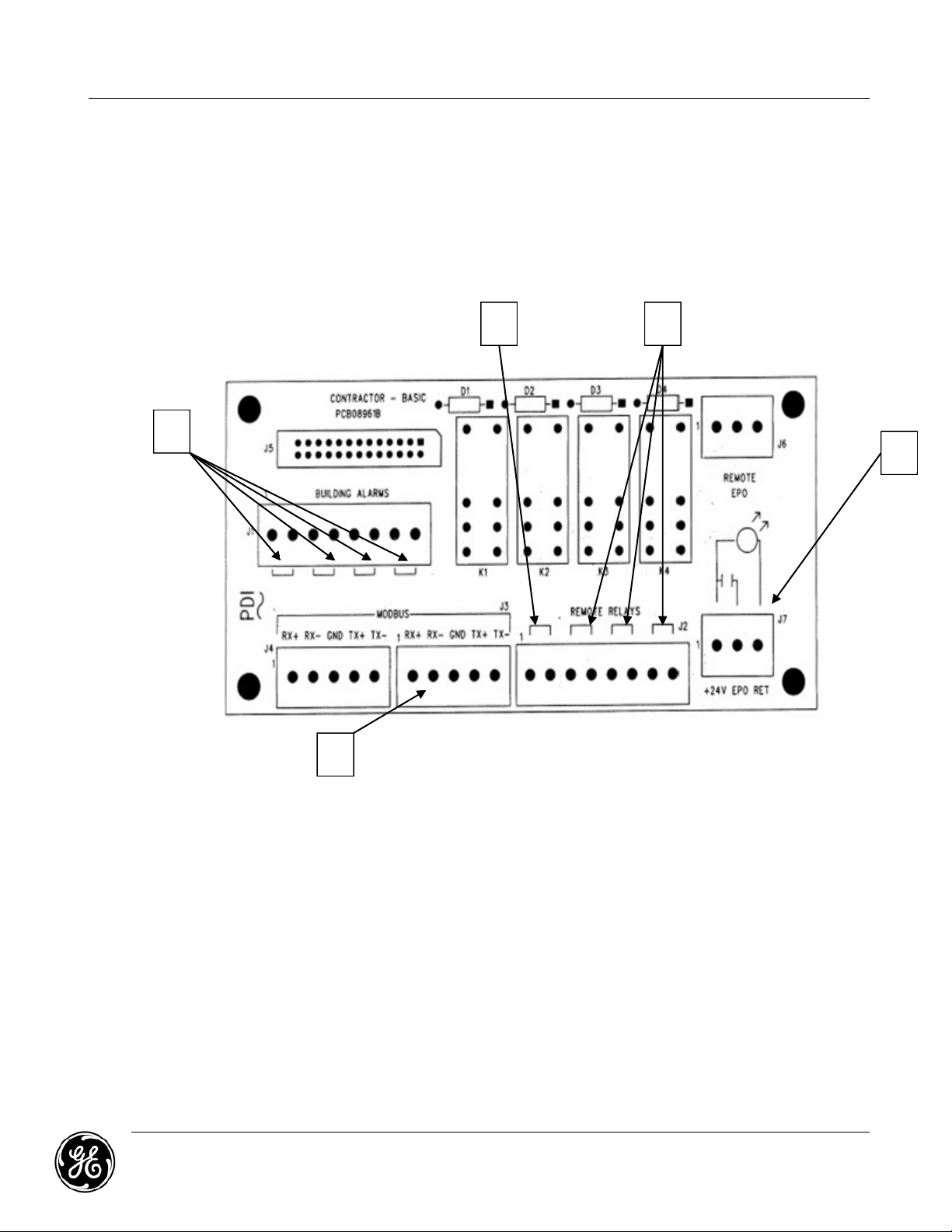
3.8. Customer Connections: Low Voltage Interface Board
2
Customer connections for remote monitoring or controls are found on the MDU’s Low Voltage
Interface Board (contractor board). This board is mounted internally within the MDU and is located
behind the safety cover between the output distribution panels in the lower front of the unit. All
interface wiring should be run within the cabinet for termination on the contractor board. All
interface wiring (building alarms, AC alarms, halon alarms, remote power off systems, etc.) and
contacts are to be provided by others.
3.8.1. GE Zenith Series Monitoring Package
1
4
Installation Procedures
5
3
1. Summary Alarm: Dry Contact point to advise when unit is in alarm.
2. Dry Contact Remote Relays: Programmable dry contacts for external output of
specific internal alarms
3. ModBus Connection: 4-wire configuration connection is located on the Customer
connection terminal block
4. Building Alarm: Input terminal block to provide unit with input on four (4) external
building alarms
5. Remote EPO: Connection point for input of remote EPO signal to system. This is a dry
contact connection point. Connection of voltage to this point can cause damage to the
unit. Connect external dry contacts to terminals marked +24v and EPO for EPO circuit. The
return position is if there is also a light for the remote EPO button.
GE ZENITH CONTROLS MDU Owner’s Manual
601 SHILOH ROAD January 2013
Plano, TX 75074 Page 18
Page 19

3.8.2. M4 Monitoring Package
Installation Procedures
GE ZENITH CONTROLS MDU Owner’s Manual
601 SHILOH ROAD January 2013
Plano, TX 75074 Page 19
Page 20

Installation Procedures
GE ZENITH CONTROLS MDU Owner’s Manual
601 SHILOH ROAD January 2013
Plano, TX 75074 Page 20
Page 21

3.8.3. Optional Low Voltage Junction Box
An optional Low Voltage Junction Box may be provided with your MDU, and is an extension
of the Low Voltage Interface Board for Customer connections external to the MDU. This
provides a convenient access to the MDU’s interface terminals without exposing the
internal components of the MDU. The box is wall-mountable, and houses a contractor
board that is connected to the MDU via 10-ft long interface cables.
3.8.4. Output Distribution Cable(s) Installation
Warning: The MDU should be de-energized before attempting to install any output
cables or assemblies. Power distribution cables and assemblies should be
installed by a qualified electrical contractor and/or a factory authorized GE
representative. For assistance call GE at (800) 637-1738.
The MDU should be in its permanent position with all input power cables properly
connected before going any further. If the unit is resting on raised floor tiles, verify the
proper cutouts have been made before continuing. Be careful not to remove an excessive
amount of floor tiles that could cause the flooring to become unstable.
Note: Special care must be taken when assigning circuit breaker positions for proper
load balancing.
Optional output distribution cables may have been shipped already attached to the unit. If
this is the case, they should be removed from the pallet and uncoiled. After they are
uncoiled, they should be inspected before installation. Remove necessary floor tiles and lay
out the cables to their respective equipment. After the cables have been properly laid out,
replace all removed floor tiles.
Installation Procedures
Note: Output cables on k-rated units must have a neutral wire that is twice the size of
the phase wires.
With the output cables unattached and the unit in its permanent position, the following
procedures should be followed:
1. Open and remove the access door to the distribution panel board or sub-feed breaker.
2. Remove dead front cover panel exposing branch circuits or sub-feed breaker(s).
3. Remove cable entry cover panel.
4. Install the appropriate circuit breakers, if not factory-installed
5. Locate an appropriate sized pre-punched conduit knock out.
6. Remove locknut from distribution cable end.
7. Feed cable conductor up through knock out and re-install locknut.
8. Tighten locknut securely.
9. Remove the necessary floor tiles and route the cable to its respective equipment.
Note: Care should be taken when placing the output cables in the units to properly
align and lace these due to the limited area for placing cables. This will be
especially true for 400kVA-750kVA rated MDU’s when the maximum number of
sub-feeds are utilized. Please call the GE factory for any assistance needed to
insure the placement of these cables.
10. Replace floor tiles.
11. Strip insulation approximately 1/2 inch from the end of the cable.
12. Connect phase wires to the output circuit breaker terminals according to the chart
below:
GE ZENITH CONTROLS MDU Owner’s Manual
601 SHILOH ROAD January 2013
Plano, TX 75074 Page 21
Page 22

Installation Procedures
Country Color coding (Phase A,B,C)
United States (US) Black, Red Blue
Canada Red, Black, Blue
United Kingdom (UK) Red, Blue, Yellow
13. Connect the ground wire (green or green with yellow tracer) to the distribution panel
ground bus.
14. If the cable requires a neutral wire (white), connect this wire to the distribution panel
neutral bus.
15. Checks to make sure all connections are securely tightened.
16. Remove the blank fillers from the distribution cover panels for the required circuit
breakers.
17. Reinstall and properly align all panels previously removed.
18. Mark (with pencil) installed breakers on the distribution cover panel identification card.
19. Check for proper phase rotation and voltage before attaching the other end of cable
to its associated equipment.
GE ZENITH CONTROLS MDU Owner’s Manual
601 SHILOH ROAD January 2013
Plano, TX 75074 Page 22
Page 23

4.0 System Monitoring
5
2
If all the previous instructions have been properly completed, it is time to activate the monitor display panel.
The monitor display panel has its own power on/off switch located in the lower left hand corner of the display
panel. Depress the on/off button and the LCD display window will illuminate indicating that power is being
supplied to the monitor. The MDU will either be equipped with a GE Zenith Series or an M4 monitoring
package. Refer to the Bill of Materials to verify your specific model
4.1. GE Zenith Series MDU Monitor
GE’s GE Zenith Series MDU Monitor features a graphic LCD panel accessible from the front of the
MDU. The monitor is part of a microprocessor based Operator Interface Module that monitors
analog power points within the MDU unit.
4.1.1. LCD Monitor Layout
System Monitoring
1. LED Status Indicator
2. Graphics Display
3. Esc/Setup
4. Navigation Controls
5. Enter/Toggle Screen
GE ZENITH CONTROLS MDU Owner’s Manual
601 SHILOH ROAD January 2013
Plano, TX 75074 Page 23
Page 24

4.1.2. GE Zenith Series Monitor Features
Feature Std / Optional
Mod Bus; RS485/RS422 Communication ports Std.
SNMP Communication Optional
LCD Graphic Display 40x16 char
Standard Contractor Board:
2A Building Alarm contacts – Qty (4)
5A Relay Contacts (summary alarm) – Qty (4)
Standard Contractor Board:
2A Building Alarm contacts – Qty (8)
5A Relay Contacts (summary alarm) – Qty (8)
Remote EPO Contacts Std.
Customized Application Specific Display Optional
Audible Alarm annunciation Std.
System Monitoring
Std
Optional
Guarded "Emergency Power off" (EPO) Pushbutton (may be disabled
at customer request)
Std.
Monitor On/Off Switch Std.
Monitor mounted on a draw-out mechanism (ease of service) Std.
BCMS for panel board branch circuits and/or sub-feed breakers Std.
Output KVA Std.
Output KW Std.
Output KWH Std.
Power Factor Std.
Synchronous Clock Std.
Date and time of day Std.
Accepts Standard CT inputs Std.
600 Volt Direct Connection on Voltage Inputs (for 600V MDU) Optional
Accuracy: ±2% current and voltage readings Std.
Min/Max Readings of metered data for BCMS Screens Std.
Password Protected Std.
Set-point controlled alarm logging Std.
Operating Range -25C - +70C
GE ZENITH CONTROLS MDU Owner’s Manual
601 SHILOH ROAD January 2013
Plano, TX 75074 Page 24
Std.
Page 25

System Monitoring
Feature Std / Optional
1-Vin: 1-V
1-Vin: 2-V
2-Vin: 1-V
out
out
out
, 1-I
, 2-I
, 1-I
out
out
out
Std.
Optional
Optional
Input Voltage THD Std.
Input Ground Current Std.
Neutral Current Std.
Phase Loss Std.
Ground Fault Alarm Std.
Time & Date Stamp for alarms Std.
Alarm Conditions
Input Frequency (Hz) (Frequency Deviation) Std.
Input Phase Rotation (Phase Rotation Error) Std.
Low Transformer Temperature alarm 180 C
High Transformer Temperature alarm 200 C
Std.
Std.
High Temperature Shutdown (may be disabled at customer request) Std.
True RMS Metering Std.
Input Voltage - Line to Line (High/Low alarm) Std.
Output Voltage - Line to Line (High/Low alarm) Std.
Output Voltage - Line to Neutral (High/Low alarm) Std.
THD - Input Voltage Std.
Output Current - A,B & C phases (phase loss and high current alarm) Std.
Current - Output neutral (High Current Alarm) Std.
Ground Current (Ground Fault Alarm) Std.
Over-Voltage / Under-Voltage Shutdown Optional
Ground Fault Shutdown Optional
Phase Rotation / Phase Loss Shutdown Optional
GE ZENITH CONTROLS MDU Owner’s Manual
601 SHILOH ROAD January 2013
Plano, TX 75074 Page 25
Page 26

4.1.3. Control Functions
The control and monitoring functions are maintained as separate circuits to prevent a
monitor malfunction from affecting equipment operation. Only excessively high
temperature in the transformer will automatically shut down the MDU system. If your MDU
is equipped with any other internal automatic shutdown system, it will be a separate
device located in the monitor tray area.
Note: GE strongly advises against any other automatic shutdown devises except
remote EPO functions.
Computer room air handling/conditioning equipment may be connected to the control
interface board (contractor board) for automatic shutdown of this equipment during
emergencies.
The emergency power off push-button and/or remote emergency power off switches will
cause the unit to shut down.
1. Emergency Power Off
A guarded and illuminated EPO push-button is interfaced to the shunt trip mechanism
of the main circuit breaker. Activation of this momentary contact push-button causes
the main circuit breaker to trip, thus removing all connected loads from the electrical
service.
System Monitoring
2. LED Indicator
A simple red light/green light display is provided for non-technical personnel. Any
monitored parameter outside of the threshold limits will illuminate a red light above
the display for identification of the fault condition. When all parameters are nominal, a
green light will illuminate.
3. Horn
The display has a horn that will sound if an alarm is present. The horn can be enabled
and disabled in the setup options.
4. LCD Display Panel
The LCD panel displays all analog inputs, digital inputs, calculated points, and alarm
indications. The LCD provides alpha-numeric display capabilities to insure correct
interpretation of the unit’s monitoring functions.
5. Front Panel Buttons
The front panel has (6) six buttons that allow navigation through the different screens
on the display. Pressing any button will turn the backlight on. After the backlight is on,
you can use them to navigate through the screens.
GE ZENITH CONTROLS MDU Owner’s Manual
601 SHILOH ROAD January 2013
Plano, TX 75074 Page 26
Page 27

4.1.4. Monitor Screens
1. Banner/Alarm Screen
The display will revert to the banner screen after some time. This screen shows the banner
and any alarms on the unit. The up and down arrow buttons will scroll through the alarms
on the screen designated by the “>” on the left side of the screen. Any alarms with “> to
clear” on the right side can be cleared by pressing the right arrow button when the alarm
is selected. There can be several pages of alarms, and scrolling down will take you to the
next page.
System Monitoring
2. MDU Device Screen
Several different devices can be connected to the display. Pressing “Enter” on the banner
screen will take you to the first device. This is the main MDU device page showing analog
parameters. Pressing the “Enter” button will switch you to other devices (if available) and
then back to the Banner Screen. Other devices can include Branch Circuit Monitoring,
Temperature Monitoring, etc. The up and down arrow buttons are used to navigate
through the different pages.
.
GE ZENITH CONTROLS MDU Owner’s Manual
601 SHILOH ROAD January 2013
Plano, TX 75074 Page 27
Page 28

System Monitoring
3. Setup Screen
The Setup Screen can be reached from the Banner Screen or any Device Screen by
pressing the “Esc” button. Once in the Setup Screen, you will have to enter the password to
continue. The default password is “GE”. The password can be changed in the Setup
Screen. Once the password is entered correctly, the lock symbol located in the top right
corner of the display will appear opened. After the lock appears opened, you can change
parameters. It will automatically lock back after a set period of time with no button
presses. The up and down arrow buttons are used to select the items to be changes. The
selected item is designated by the “>” on the left side of the screen. The left and right arrow
keys are used to change the information. For the options where text is changed (banner,
password, etc.), the “>” will be replaced by a “–“and an underscore will appear under the
letter or number to be changed. The up and down arrow buttons will change the letter or
number. When you are finished, you must scroll back to the beginning. The “–” will return to
a “>” and you can scroll to the next setup option.
Typical Setup Options
1 Banner
2 Devices
Upstream
3
Modbus
Downstream
4
Modbus
5 Password Allows the user to set or change the password (up to six-characters).
6 Time and Date
7 Horn Used to enable or disable the horn.
8 Devices
GE ZENITH CONTROLS MDU Owner’s Manual
601 SHILOH ROAD January 2013
Plano, TX 75074 Page 28
User-customizable banner that shows on the main banner/alarm
screen. This can be changed while in setup mode.
Specifies the number of devices connected to the monitor via
ModBus Protocol. Each device connected to the display must have a
different modbus address.
This is used to change the modbus settings of the port that the
customer uses to connect to read modbus information. The address,
baud rate, and parity can all be changed.
This is used to change the modbus settings of the port that connects
to the devices in the unit to read modbus information. The baud rate
and parity can all be changed. GE does not recommend changing the
ModBus settings as communication problems may occur.
This is used to set the time and date. To change AM and PM you
have to roll the hour past 12. When you have the information
entered correctly move to the “SET” and hit enter.
The next screen is used for device setup. A device such as BCMS can
be set up to disable certain alarms that are not desired. You can also
change the panel board size for trending info.
Page 29

System Monitoring
For SNMP or Web enabled MDU’s, the last screen is used to change
all the SNMP information.
a. IP – The IP address of the unit
b. SNM – Subnet Mask
9 SNMP/WEB
c. DGW – The Default Gateway
d. DNS – The Domain Name Server
e. TDS – The Trap Destination Server
f. Trap Enable – Specifies whether or not you want traps sent
out.
More information is available in the SNMP section of this manual.
Note: There can be several pages of options as a result of special project
requirements
GE ZENITH CONTROLS MDU Owner’s Manual
601 SHILOH ROAD January 2013
Plano, TX 75074 Page 29
Page 30

4.1.5. Contractor Connections
1. Printed Circuit Boards (PCB)
A low voltage control junction box shall not be included on this equipment. All Remote
Emergency Power Off, building alarms, output relays, communication ports and other
control wiring shall be terminated onto a Contractor Interface Board which is an integral
component within the MDU system itself.
Standard Interface Board
a. Remote Emergency Power Off interconnect positions
b. Four (4) Relay Contacts (NO contacts) rated 5 amps (summary alarm)
c. Four (4) Building alarm contacts rated 5 amps
d. Remote monitoring connection ports (ModBus RTU Protocol, RS-422/485)
Advanced Interface Board (optional)
a. Remote emergency power off interconnect positions
b. Eight (8) Relay Contacts (NO contacts) rated 5 amps (summary alarm)
c. Eight (8) Building alarm contacts rated 2 amps
d. Remote monitoring connection ports (ModBus RTU Protocol, RS-422/485)
e. Local monitoring of GE approved devices (ModBus RTU Protocol, RS-422/485)
Note: The Tx+ and Tx- are transmission points, and should be connected to the
receiver of the monitoring system. The Rx- and Rx+ are receiving points.
System Monitoring
4.1.6. Communications
1. ModBus RTU
a. Hardware
The GE Zenith™ Series MDU monitor has a 4 or 2 wire plus ground, RS-422/RS-485
compatible interface. The communications parameters for the interface are 9600
baud, 8 bit, even parity, and 1 stop bit as standard with options for odd and no parity
and 2400, 4800 and 19200 baud. For (4) four wire all commands are sent to the
monitor on (1) one pair and all replies from the monitor are on the other pair. The pair
on which an M4 sends will be in a high impedance state until an M4 responds to a
command. For (2) two wire all commands are sent to a GE ZENITH™ SERIES and all
replies from a GE ZENITH™ SERIES are sent on the same pair. The pair will be in a high
impedance state until an M4 responds to a command. For (2) two wire
communications the transmit + and receive + must be jumped together as well as the
transmit - and receive -. You must also verify that the packet is complete before
another transmit is initiated. The interface is isolated.
b. Packets
The monitor never initiates communications, rather it responds to command packets
sent to it. Each command packet sent to the monitor has an address byte that
includes the address of the destination of that monitor. It does not respond to packets
addressed to “0”.
GE ZENITH CONTROLS MDU Owner’s Manual
601 SHILOH ROAD January 2013
Plano, TX 75074 Page 30
Page 31

System Monitoring
c. Registers
Most of the analog values are 2 byte integers representing a parameter such as input
voltage, current, etc. KWH takes 2 of the 2-byte integers. Some parameters require
scaling, and are noted in the points list.
d. Prerequisites
Each connected monitor must have a unique address between 1 and 255. The Setup
screen is used to set up the address of the monitor. It also uses additional sequential
address for each device. The number of devices is also in the setup screen.
Note: improper configuration of a GE Zenith Series Monitor may block other
monitors or devices on the chain.
e. Biasing and Termination
Since there is only one master, the master can and should drive its transmit pair
continuously. But slaves do not drive the master’s receive pair until they send the
master a response. As soon as they are finished, they stop driving the master’s receive
pair. This is necessary since other slaves may need to send responses on the master’s
receive pair. Therefore, most of the time the master’s receive pair is just floating. The
master’s adapter SHOULD drive its transmit pair continuously and, of course, never
drive the receive line, except in an effort to be 2 wire compatible. Most adapters do not
drive the transmit pair until the start of the first character sent, and only continue to
drive the transmit pair a few milliseconds after the last character (meaning the
master’s transmit pair is usually just floating most of the time).
f. Wiring
RS485/RS422 cable length can be up to 4000ft if the proper cable is used. To achieve
this you need to have a shielded cable with 2 twisted pairs and shield/ground. The two
transmit lines need to be in one twisted pair and the two receive lines need to be in the
other twisted pair. The cable resistance should be 27 ohms/1000ft @ 1 kHz or less and
the mutual capacitance should be 14pf/ft @ 1 kHz or less. RS422 is typically (4) four
wire, and RS485 is typically (2) two wire and is slower than RS422.
g. Supported Commands and Replies
Note that these are typical for the product. See the point list for specifics.
a. Report slave ID
Sent Hex: 01 11 C0 2C
Reply Hex: 01 11 0D EA FE 52 50 50 20 44 69 73 70 6C 61 79 A3 A6
b. Read holding registers
Sent Hex: 01 03 00 00 00 01 84 0A
Reply Hex: 01 03 02 00 00 B8 44
c. Write single register
Sent Hex: 01 06 00 00 00 00 89 CA
Reply Hex: 01 06 00 00 00 00 89 CA
The flag and data numbers shown here are in “human” numbers. The first analog
channel is numbered 1 but, in software, it is accessed by an index value of 0. It is
common for a system to be one register off due to this situation, so it is important to
verify that the registers are correct early in the configuration procedure. As similar
readings are in adjacent registers, being one register off is not necessarily apparent.
GE ZENITH CONTROLS MDU Owner’s Manual
601 SHILOH ROAD January 2013
Plano, TX 75074 Page 31
Page 32

2. SNMP
a. Hardware
The GE Zenith Series Monitor has an expansion board that can be used to provide
SNMP. The expansion board plugs into the main display board. The SNMP parameters
are configured in the setup menu on the third page. See the setup menu for more
information about configuring the SNMP. SNMP version 1 is supported.
b. Prerequisites
Each connected monitor must have a unique address. The Setup screen is used to set
up the address of the monitor.
Note: improper configuration of a GE Zenith Series Monitor may conflict with
other monitors or devices on the network.
c. Wiring
The connection to the SNMP expansion board is made with a standard Ethernet cable.
d. Supported Commands
Note that these are typical for the product. See the mib file associated with your MDU
configuration for specifics.
a. snmpget
b. snmp
c. write single register
System Monitoring
GE ZENITH CONTROLS MDU Owner’s Manual
601 SHILOH ROAD January 2013
Plano, TX 75074 Page 32
Page 33

5.0
Branch Circuit Monitoring System (BCMS)
Your
the Plus version as an
An installed BCMS
currents. The total currents a
Plus
calculations.
Parameters are displayed locally on the
5.1.
GE
601
Plano, TX 75074
option
Calibration and Set
Panelboard #2 Even
Panelboard #2 Odd
Panelboard #1 Even
ENITH
S
MDU
option
Ribbon cable connection for
Ribbon cable connection for
Ribbon cable connection for
Ribbon cable connection for
Panelboard #1 Odd
HILOH
may be equipped with
BCMS Components
5.1.1.
ONTROLS
OAD
in addition to current monitoring,
24 VAC Connection
-
Basic
Acquisition Module
The Acquisition module consists of a fuse, small control transformer and a printed circuit
board (Figure 1 in Appendix A) mounted on a plate. There can be up to 4 CT modules
connected to this board, for a to
digital points. There are also eight terminals for Power CT’s to enable the BCMS to monitor
total current. It sends this information out via ModBus RTU to the local display or customer
supplie
-
up Port (J16)
(2,
(J5
(1, 3, 5…)
(J4
(J3
(J2
added feature to the
option renders the capability to
4, 6…)
PB2B)
PB2A)
(2, 4, 6…)
—
(1, 3, 5…)
—
d monitoring system.
PB1B)
PB1A)
re a summation of the branch circuit breakers on each panel board
GE’sBranch
GE Zenith Series
MDU Owner’
MDU
Circuit Monitoring System
system
measures and monitors source voltages
system
tal of 84 CT’s. There are terminals for six voltages and four
s Manual
measure
MDU
Monitor.
and monitor panel board and/or sub
Branch Circuit Monitoring System (BCMS)
(
BCMS
BCMS
) in either the
TB1
Ground Input
Neutral Input
120 VAC Input
Source 1 Voltage (J9)
RetRXRX+ (TX+)
TX
TX+
Source 2 Voltage (J10)
Source Breaker Closed (J1)
Neutral and Grd. CT Currents (J11)
Panel board 2 CT Currents (J13)
Panel board 1 CT Currents (J12)
Factory Programming Port
(TX
and determines
)
Basic
.
RS485
(J14)
January 2013
Page
version or
The BCMS
feed
power
33
.
-
,
-
-
-
—
—
Z
C
R
Page 34

GE
601
Plano, TX 75074
ENITHSHILOH
5.1.2.
5.1.3.
ONTROLS
OAD
Current Transformers (
The current transformers are
each branch breaker is then run through the appropriate current transformer before being
connected to the breaker. These are mounted to a printed circuit board with the solid
core solution for
ea
Current Transformers (CT’s)
When attaching solid
white wire should face the load. Always remember “label faces load”. The label can be
identified from the imprinted “H” and Manufacture date.
ch have two wires for existing p
new installation applications and individually mounted split core CT’s that
-
core CTs for sub
MDU Owner’
core CTs for sub
Panel
normally placed on both sides of a panel board. The wire to
normally placed on both sides of a panel board. The wire to
board
anel
s Manual
board
board applications are available.
feed monitoring
feed monitoring
CT’s)
Bran
ch Circuit Monitoring System (BCMS)
purposes make sure the label and
January 2013
Page
34
-
Z
C
R
Page 35

Branch Circuit Monitoring System (BCMS)
5.2. BCMS Local Monitoring via GE Zenith Series MDU Monitor
5.2.1. BCMS Device Setup
Prior to this setup, ensure that all devices have been connected to the monitor via ModBus.
Each BCMS device being added the monitor needs to be assigned a unique ModBus
address. The MDU device is typically assigned address “1”, while subsequent devices are
assigned “2…, 3”, etc.
Device List:
To add a BCMS device, navigate to the main monitor setup screen as described on page
28. While on the main monitor setup, position the cursor “>” on “DEVICES” (using the up or
down keys) and press “ENTER”. This will take the user to the Device List illustrated on this
page. Based on detected connections, the GE Zenith Series Monitor automatically
generates this list.
Device Settings:
Position the cursor on the desired device in the list and
Press “ENTER” to modify settings for that particular device on the next screen (illustrated in
bottom-right section of this page). Once settings are configured, return to the Banner
Screen described on page 27 by pressing “ESC”.
GE ZENITH CONTROLS MDU Owner’s Manual
601 SHILOH ROAD January 2013
Plano, TX 75074 Page 35
Page 36

5.2.2. Panel board Information
While at the main MDU device screen, press “ENTER” each time to navigate the user
through the various connected devices that have been activated. Once in the BCMS device
summary screen, use the up or down arrow keys to navigate through branch circuit
parameters for each panel board.
Panel board Load Summary:
Displays percentage load per branch circuit on the panel.
Branch Circuit Monitoring System (BCMS)
Panel board Branch Circuits:
Displays currents and alarm status for each branch circuit on the panel. The user scrolls
through the 42-circuits using the up or down arrow keys.
GE ZENITH CONTROLS MDU Owner’s Manual
601 SHILOH ROAD January 2013
Plano, TX 75074 Page 36
Page 37

Branch Circuit Monitoring System (BCMS)
Panel board Main Parameters:
Shows total currents and voltages for the panel board.
Panel board Power Calculations:
Displays true RMS kW, kVA, kVAR, and also shows kWH.
Panel board Current Trending:
Displays current trends for the panel board over a period of time
GE ZENITH CONTROLS MDU Owner’s Manual
601 SHILOH ROAD January 2013
Plano, TX 75074 Page 37
Page 38

Branch Circuit Monitoring System (BCMS)
1. ModBus Data Interface
The normal data protocol is ModBus RTU and uses a 4-wire plus shield, multi-point
EIA/TIA-422-B (RS-422) interface. The default communications parameters for the
interface are 9600 baud, 8 bit, even parity, and 1 stop bit. Parity can be changed.
Optionally, the BCMS data interface can be strapped for 2 wire plus shield RS-485, and
2 wire plus ground RS-232. Note that RS-232 is only possible if there is only one BCMS
(there is no multi-point or daisy chain) and the distance to the computer is less than 20
ft. The communications parameters remain the same. Address 1 is the default base
address. It is changed from the service port.
GE ZENITH CONTROLS MDU Owner’s Manual
601 SHILOH ROAD January 2013
Plano, TX 75074 Page 38
Page 39

6.0 System Troubleshooting
S
P
R
6.1. System Safety Precautions
DANGER: There is high voltage equipment inside the MDU cabinet. Always use extreme
caution and follow all recommended safety precautions.
DO NOT operate the MDU without all exterior panels properly in place.
DO NOT allow unauthorized personnel to perform any services on your MDU. Please contact
GE’s field support division at (800) 637-1738 for your authorized service agent and for
assistance.
DO NOT touch any printed circuit board without consulting GE’s field support division.
Improper handling of circuitry could cause damage to your MDU and void the
warranty.
If following the troubleshooting procedures below does not repair your MDU, contact GE’s
Service Team at (800) 637-1738 for scheduling service.
6.1.1. Troubleshooting guidelines (GE Zenith Series Monitoring Package)
System Troubleshooting
YMPTOM
No power to unit Unit not connected to
Individual output
circuit has no
power.
No output from unit
but indicators are
on
No upstream
communication
No audible
indication
No able to scroll
thru screens
Not able to see
MDU output
readings
Unable to see BCMS
(optional) panels on
front panel
ROBABLECAUSE
power J box. Main
Breaker not enabled
Output circuit breaker
and or cable is not
connected to MDU.
Main breaker is
turned off or has
tripped
Not able to remotely
communicate to the
monitor
No audible when an
alarm occurs
Cannot see panel
information
No output voltages or
currents are
displayed
No BCMS currents are
displayed on monitor
screens.
EMEDY
Connect unit to Power J box.
Turn on or reset main circuit breaker
Connect output circuit to MDU and
energize circuit.
Check LCD Display for active alarms,
then reset main breaker.
Press the ESC key and verify remote
upstream address, baud rate, & parity
are set correctly.
Press the ESC key and verify the horn is
enabled.
Press the enter button firmly to view
MDU information
Once on the input screen, use the Up
or down arrows to access output
screens.
Verify a BCMS is connected to the
downstream port and press the esc
key to setup the number of additional
Panel boards added.
GE ZENITH CONTROLS MDU Owner’s Manual
601 SHILOH ROAD January 2013
Plano, TX 75074 Page 39
Page 40

GE Zenith Series Monitor Alarm Description
7.0 GE Zenith Series Monitor Alarm Description
ALARM NAME ALARM MESSAGE ALARM DESCRIPTION
Input Phase Rotation "PHASE ROTATION" If the phase rotation is incorrect on the unit's input, the
unit will alarm.
High Temperature Transformer "THERM OVERTEMP” If the 180oC thermal switches located in the windings of
the transformer reach their rating or better, the unit
will alarm. First part of a two stage high transformer
temperature alarm system.
High Temperature Transformer
Shutdown
Input Voltage Phase A-B High “INPUT VOLT AB HIGH" If the input voltage on phase A-phase B goes above the
Input Voltage Phase B-C High “INPUT VOLT BC HIGH" If the input voltage on phase B-phase C goes above the
Input Voltage Phase C-A High "INPUT VOLT CA HIGH" If the input voltage on phase C-phase A goes above the
Input Voltage Phase A-B Low “INPUT VOLT AB LOW" If the input voltage on phase A-phase B goes below the
Input Voltage Phase B-C Low “INPUT VOLT BC LOW" If the input voltage on phase B-phase C goes below the
Input Voltage Phase C-A Low "INPUT VOLT CA LOW" If the input voltage on phase C-phase A goes below the
Output Voltage Line A-B High “OUTPUT VOLT AB HIGH" If the output voltage on line A-line B goes above the
Output Voltage Line B-C High " OUTPUT VOLT BC HIGH" If the output voltage on line B-line C goes above the
Output Voltage Line C-A High " OUTPUT VOLT CA HIGH" If the output voltage on line C-line A goes above the
Output Voltage Line A-B Low " OUTPUT VOLT AB LOW" If the output voltage on line A-line B goes below the
Output Voltage Line B-C Low "OUTPUT VOLT BC LOW” If the output voltage on line B-line C goes below the
Output Voltage Line C-A Low "OUTPUT VOLT CA LOW" If the output voltage on line C-line A goes below the
Output Voltage Line
A - Neutral High
Output Voltage Line
B - Neutral High
Output Voltage Line
C - Neutral High
"THERM HIGHTEMP" If the 200
the transformer reach their rating or better, the unit's
main circuit breaker will shunt trip, shutdown the unit.
Second part of a two stage high transformer
temperature alarm system.
preset level line to line, the unit will alarm.
preset level line to line, the unit will alarm.
preset level line to line, the unit will alarm.
preset level line to line, the unit will alarm.
preset level line to line, the unit will alarm.
preset level line to line, the unit will alarm.
preset level line to line, the unit will alarm.
preset level line to line, the unit will alarm.
preset level line to line, the unit will alarm.
preset level line to line, the unit will alarm.
preset level line to line, the unit will alarm.
preset level line to line, the unit will alarm.
“OUTPUT VOLT AN HIGH" If the output voltage on line A-Neutral goes above the
preset level line to Neutral, the unit will alarm.
“OUTPUT VOLT BN HIGH" If the output voltage on line B-Neutral goes above the
preset level line to Neutral, the unit will alarm.
“OUTPUT VOLT CN HIGH" If the output voltage on line C-Neutral goes above the
preset level line to Neutral, the unit will alarm.
o
C thermal switches located in the windings of
GE ZENITH CONTROLS MDU Owner’s Manual
601 SHILOH ROAD January 2013
Plano, TX 75074 Page 40
Page 41

GE Zenith Series Monitor Alarm Description
Output Voltage Line
A - Neutral Low
Output Voltage Line
B - Neutral Low
Output Voltage Line
C - Neutral Low
Output Current Line A High "OUTPUT CURR A HIGH" If the output current on line A goes above the preset
Output Current Line B High "OUTPUT CURR B HIGH" If the output current on line B goes above the preset
Output Current Line C High "OUTPUT CURR C HIGH" If the output current on line 3 goes above the preset
Ground Current High "OUTPUT CURR GND
Neutral Current High "OUTPUT CURR NEU
Total System kVA High "KVA TOTAL HIGH" If the total system kVA goes above the preset level, the
Output Phase A kVA High "KVA A HIGH" If the output kVA on Phase "A" goes above the preset
Output Phase B kVA High "KVA B HIGH" If the output kVA on Phase "B" goes above the preset
Output Phase C kVA High "KVA C HIGH" If the output kVA on Phase "C" goes above the preset
Total System kW High "KW TOTAL HIGH" If the total system kW goes above the preset level, the
Output Phase A kW High "KW A HIGH" If the output kW on Phase "A" goes above the preset
Output Phase B kW High "KW B HIGH" If the output kW on Phase "B" goes above the preset
Output Phase C kW High "KW C HIGH" If the output kW on Phase "C" goes above the preset
Emergency Power Off "EPO" This alarm can be activated in by pushing the unit's EPO
Remote Emergency Power Off "REMOTE EPO" This alarm can be activated in by closing the contacts
“OUTPUT VOLT AN LOW" If the output voltage on line A-Neutral goes below the
preset level line to Neutral, the unit will alarm.
“OUTPUT VOLT BN LOW" If the output voltage on line B-Neutral goes below the
preset level line to Neutral, the unit will alarm.
“OUTPUT VOLT CN LOW" If the output voltage on line C-Neutral goes below the
preset level line to Neutral, the unit will alarm.
level, the unit will alarm.
level, the unit will alarm.
level, the unit will alarm.
If the ground current goes above the preset level of 10
HIGH"
HIGH"
Amps, the unit will alarm.
If the neutral current goes above the preset level, the
unit will alarm.
unit will alarm.
level, the unit will alarm.
level, the unit will alarm.
level, the unit will alarm.
unit will alarm.
level, the unit will alarm.
level, the unit will alarm.
level, the unit will alarm.
button. When EPO button is pushed, the alarm is
activated and he unit’s main input circuit breaker will
then be shunt tripped off line.
on the contractor board. When Remote EPO button is
activated, the alarm is activated and he unit’s main
input circuit breaker will then be shunt tripped off line.
GE ZENITH CONTROLS MDU Owner’s Manual
601 SHILOH ROAD January 2013
Plano, TX 75074 Page 41
Page 42

8.0 Special Instructions
8.1. Output Panel boards
MDUs that are supplied with output panel boards should have all the output loads balanced at the
panel boards. The objective is to place equivalent current wave forms and magnitude on each
output. With most (3) three phase loads containing a full wave bridge rectifier, distributing the 3 pole
breakers (by ampacity) evenly across matched Panel boards provides optimum balancing. Duty
cycle, if available, should also be considered. Single phase loads with high third harmonics should
also be evenly balanced across the Panel boards. Below are the steps to follow for proper balancing
of circuits.
A. Divide all output into (3) three categories by breaker pole position (1 pole, 2 pole, 3 pole).
B. Subdivide the 3 categories by breaker size (ampacity).
C. Assign the largest 3 pole breaker to panel board #1.
D. If there is an even number of the larger 3 pole breakers, assign them evenly between the panel
boards. If you are unable to assign them evenly, then assign smaller 3 pole breakers to the
panel having fewer breakers.
E. Perform steps c) and d) in regards to the next size down, 3 pole breakers. Continue with this
procedure until all 3 pole breakers are installed.
F. Repeat this process with all 2 pole and 1 pole breakers respectively. Units that are equipped
with four (4) or six (6) Panel boards should first divide the circuits into groups of two (for 4 Panel
boards) and groups of three (for 6 Panel boards). Once the circuits are evenly divided, proceed
with the above steps.
Special Instructions
Note: Do not assign only single pole or two pole breakers to an individual panel board.
8.1.1. Panel board manufacturers
When choosing the proper distribution breakers for use on a specific panel board within
your MDU, be sure to use only distribution breakers that are compatible with associated
panel board. Below is a list of compatible distribution breakers for specific Panel boards. If
you need any assistance in choosing the proper breakers please contact GE’s field support
division at (800) 637-1738.
1. General Electric Panel boards: Use only General Electric (type AQL3422AT) type THQB,
THHQB, TXQB, or THQL breakers.
If another brand panel board not mentioned above is placed in your MDU, then be sure and
only use a distribution breaker that is compatible with that manufacturer. You may need to
contact the panel board manufacturer to ensure compatibility.
GE ZENITH CONTROLS MDU Owner’s Manual
601 SHILOH ROAD January 2013
Plano, TX 75074 Page 42
Page 43

8.2. Output Dedicated Circuit Breakers (Sub-Feeds)
Certain MDUs will be designed for a specific application such as a large mainframe. These units may
be equipped with individual molded case output circuit breakers that should be sized for these
specific applications. For these applications, please consult your submittal package for proper power
connections. Consult GE’s field support division at (800) 637-1738 before installing any additional
output breakers to these units.
8.3. Low Voltage Interface Board (Contractor Board)
All low voltage connections for HVAC shutdown, Remote Emergency Power Off (REPO), etc. are made
on the Low Voltage Interface Board generally located behind the MDU’s front upper interior cover on
the front of the logic /monitor plate. Included on the Low Voltage Interface Board are:
1. Connections for one DPDT relay that activates whenever the EPO circuit is activated.
2. Two sets of connections for a REPO system.
3. Connections for (1) one DPDT relay that will change state when power is either on or off.
4. Four sets of customer contacts for building and/or environmental alarms.
Refer to the specifications/drawings section of this manual for detailed drawings of the customer
interface board.
Special Instructions
GE ZENITH CONTROLS MDU Owner’s Manual
601 SHILOH ROAD January 2013
Plano, TX 75074 Page 43
Page 44

9.0 Warranty, Maintenance and Terms
9.1. GE Service Department
The GE Service Department is proud to provide support for its broad range of power quality
products. GE Zenith, Static Switch, Computer Shield, Site Monitoring, and Line Conditioning series
products all are manufactured, sold, and serviced under the GE umbrella. Our commitment to
servicing these products begins with our START UP service, and continues with our factory Warranty
and is continuously maintained through our Preventative Maintenance Contracts.
9.1.1. GE’s Standard Warranty
GE’s Standard Warranty is good for all products for 18 months following shipment or 12
months after START UP, whichever comes first. After the warranty period is over, customer
is on Time & Material basis unless a Preventative Maintenance contract is in effect.
9.1.2. Start Up
GE START UP is mandatory for all MDU’s purchased, and is a sure way of getting your
power quality equipment up and running as you need it. By following our standard START
UP procedures, you can be assured that you power quality equipment will perform to your
requirements. Some of the features and benefits are:
GE START UP services provide a factory-trained customer support engineer to oversee
visual inspection of the installation and system calibration.
GE START UP service also provides factory-trained customer support engineers to
assist with operational training.
Warranty, Maintenance and Terms
9.1.3. Maintenance Contracts
GE Maintenance contracts help to ensure that the reliability of your critical power systems
is intact. By following our stringent maintenance procedures, GE’s factory trained customer
support engineers provide extra insurance for the availability of critical systems, and
maximize the company’s profitability.
9.1.4. Time and Materials
In most cases the customer will be covered by START UP service or Maintenance Contracts,
however, there may be times when the customer needs GE service and lacks the benefits
that these two packages provide. Therefore, GE provides Time and Material coverage for
those in need of our customer support engineers.
GE ZENITH CONTROLS MDU Owner’s Manual
601 SHILOH ROAD January 2013
Plano, TX 75074 Page 44
Page 45

9.2. GE Maintenance Contracts
9.2.1. Features & Benefits
A GE maintenance contract helps ensure that the reliability of your critical power systems
remain intact.
1. A promise of prompt courteous service.
With factory-trained technicians in nearly every major city in North America, GE is able to
respond within four hours of a support call and provide on-site assistance in emergency down
time situations.
GE provides 24 hours a day, 7 days a week direct line to Service (800-637-1738).
There are no added costs for weekends, nights or holidays.
2. Two comprehensive Preventative Maintenance visits annually.
Factory trained service engineers will visit your site twice annually using the state of the art
diagnostics systems.
Infrared Scanner provides information that can determine impending failures on
connections and busing before they become a catastrophic problem.
Harmonic Analyzer provides real time information on the effects harmonic currents are
having on your power distribution system (performed on an annual PM visit).
Other services include:
Thorough visual inspection of all parts (bulbs, displays, missing hardware, cleanliness,
and corrections as required).
Verification of monitor calibration and correction.
Check load balance, kVA usage and building alarms.
Complete hard copy report summarizing all tests and analysis.
Warranty, Maintenance and Terms
3. GE provides Flexibility and Commitment.
GE can customize your service to meet your needs (number of PM visits per year, scope
of coverage (e.g. parts not included), length of contract, etc.).
GE provides nationwide factory trained and authorized service engineers ready to meet
your demands.
Guaranteed parts availability. GE ensures that all parts needed to service your equipment
or the latest technology will be available to you.
GE ZENITH CONTROLS MDU Owner’s Manual
601 SHILOH ROAD January 2013
Plano, TX 75074 Page 45
Page 46

10.3 Warranty Validation Request
(If different from above)
Serial #
Location
Contact
Contact Phone
Thank you for your recent purchase of GE equipment. The warranty for your equipment becomes
effective from the date of commissioning by a GE Authorized Technician. Please complete the
information below and return to GE by fax at (804) 737-1549. We will activate the warranty and
return the warranty agreement for your records.
Customer Information
Customer:
Location:
Contact:
Contact Phone:
Contact E-mail:
Equipment Information
Warranty, Maintenance and Terms
GE use only
Commissioning Date:
Warranty Commencement:
Warranty Completion Date:
GE ZENITH CONTROLS MDU Owner’s Manual
601 SHILOH ROAD January 2013
Plano, TX 75074 Page 46
Page 47

9.4. Warranty Agreement
Serial #: Model #:
Equipment Location Address:
Contact Name:
Seller warrants to Buyer that, unless otherwise stated by the Seller, any products or services furnished
hereunder will be free from defects in material, workmanship and title, under normal use and services and
quality specified in Seller’s quotation. This warranty shall apply to failure to meet said warranties (excluding
any defects in title) which appear within twelve (12) months from date of startup or eighteen (18) months
from the date of shipment, whichever occurs first.
The conditions of any tests shall be mutually agreed upon and Seller shall be notified of, and may be
represented at, all tests that may be made. The warranties and remedies set forth herein are conditioned
upon (a) proper transportation, handling, storage, installation, commissioning, operation, use and
maintenance, and conformance with any applicable recommendations of Seller and any applicable laws,
regulations or codes (b) Buyer promptly notifying Seller of any defects and, if required, promptly making the
product available for correction. This warranty shall not apply (a) if Customer or any other unauthorized
person has made any modifications, alterations, or repairs to the Product not authorized by Seller, including
Customer’s use of parts in conjunction with the Product not admitted or delivered by Seller, (b) to a Product
with removed or altered serial numbers, (c) to a Product damaged by acts of God, sources external to the
Product, misuse, accident, abuse, neglect, negligence, or use beyond rated capacity, and (d) if GE authorized
field service technician does not commission the Product.
Warranty, Maintenance and Terms
(_____)_
If any product or service fails to meet the foregoing warranties (except title), Seller shall thereupon correct
any such failure either, at Seller’s option, (i) by repairing any defective or damaged part or parts of the
products, and/or re-performing any defective service, or (ii) making available any necessary repaired or
replacement parts or necessary service which will be performed during normal working hours on a straight
time basis. Repaired or replaced products will be returned FCA (INCOTERMS 2000) the Seller’s plant or other
mutually agreed upon point of shipment. If re-performance is not practicable, Seller will furnish without
charge services in an amount essentially equal to those that, in the sole judgment of Seller, would have
been required for re-performance. Where a failure cannot be corrected by Seller’s reasonable efforts, the
parties will negotiate an equitable adjustment in price.
This Paragraph sets forth the exclusive remedies for claim (except title) based on defect, failure or
nonconformity of the products or services supplied, whether claim is in contract or tort (including
negligence) or otherwise and however instituted. Upon the expiration of this warranty, all such liability shall
terminate. Except as set forth in “Patents” the foregoing warranties are exclusive and in lieu of all other
warranties or conditions whether written, oral, implied or statutory. No implied or statutory warranties or
conditions of merchantability or fitness for particular purpose shall apply. Seller does not warrant any
products or services of others, which Buyer has designated.
This agreement shall be effective from ______________to _______________.
GE ZENITH CONTROLS MDU Owner’s Manual
601 SHILOH ROAD January 2013
Plano, TX 75074 Page 47
Page 48

10.0 Appendices
T
10.1. Appendix A – MDU Input Breaker Sizing Chart
Main Breaker Amperage Rating Chart
Appendices
INPUT VOLTAGE
RANSFORMER LESS
GE ZENITH
kVA 208/120 Vac 208 Vac 480 Vac 600 Vac
15 60 Amp 60 Amp 30 Amp 20 Amp
30 110 Amp 110 Amp 50 Amp 40 Amp
50 175 Amp 200 Amp 80 Amp 70 Amp
75 300 Amp 300 Amp 125 Amp 100 Amp
100 350 Amp 400 Amp 175 Amp 125 Amp
125 500 Amp 500 Amp 200 Amp 175 Amp
150 600 Amp 600 Amp 250 Amp 200 Amp
200 700 Amp 800 Amp 350 Amp 250 Amp
225 800 Amp 800 Amp 400 Amp 300 Amp
300 N/A N/A 500 Amp 450 Amp
400 N/A N/A 700 CF
500 N/A N/A 800 Amp CF
625 N/A N/A 1000 CF
750 N/A N/A 1200 CF
GE ZENITH CONTROLS MDU Owner’s Manual
601 SHILOH ROAD January 2013
PLANO, TX 75074 Page 48
Page 49

10.2. Appendix B - Class A Computing Device: Information To User
The following warning or similar statement shall be provided in a conspicuous location in the
operation manual so that the user of a class a computing device is aware of its interference
potential. Additional information about corrective measures may also be provided to the user at the
manufactures option.
Warning: This equipment generates, uses, and can radiate radio frequency energy, and if not
installed and used in accordance with the instruction manual, may cause
interference to radio communications. It has been tested and found to comply with
the limits for a class A computing device pursuant to subpart B of part 15 of FCC
rules, which are designed to provide reasonable protection against such
interference when operated in a commercial environment. Operation of this
equipment in a residential area is likely to cause interference, in which case the
user, at his own expense, will be required to take whatever measures may be
required to correct the interference.
Appendices
GE ZENITH CONTROLS MDU Owner’s Manual
601 SHILOH ROAD January 2013
PLANO, TX 75074 Page 49
Page 50

11.0 Spare Parts
The following is the recommended spare parts requirements for GE’s standard Monitored Distribution Units.
GE recommends that (1) one complete spare parts kit be kept for every (5) units at one site.
Some MDU’s are manufactured to meet a special application and/or a special configuration. These units may
require that a customized spare parts kit be ordered. If you require a special spare part kit, please contact
GE’s Local Representative for assistance.
The parts contained in a spare parts kit are OEM parts and have been tested to assure reliability and
functionality. GE recommends that only OEM parts be replaced in its MDU’s. Failure to do so could result in
the unit’s warranty being voided.
All parts should be replaced by a GE factory authorized engineer only. Some parts may require special
calibration and/or installation procedures.
It is recommended that spare parts kits be stored in a properly controlled storage area that is easily
accessible with 24 hour access in case of emergency requirements.
Spare Parts
The following are details for available Kit Options for your MDU.
For pricing and availability of spare parts kits please contact GE's Local Representative.
GE ZENITH CONTROLS MDU Owner’s Manual
601 SHILOH ROAD January 2013
PLANO, TX 75074 Page 50
Page 51

Spare Parts
11.1. Spare Parts Kits - GE Zenith MDU with M4 Monitoring Package
11.2. Spare Parts Kits - GE Zenith MDU with GE Zenith Series Monitoring
Package
11.2.1. GE Zenith Series MDU - “Option A” Kit
Qty Description Part #
5 Assorted Fuses
1 Control Power Transformer XMR06314
5 South-co Panel Retainer FAS-12-11014-12
5 South-co Panel Clip FAS-12-11017-11
5 South-co Panel Fastener FAS-121120511
5 South-co Panel Washer FAS-85-46-10141
1 GE Zenith Series Data Acquisition Card PCB09647
11.2.2. GE Zenith Series MDU - “Option B” Kit
Qty Description Part #
GE Zenith MDU GE Zenith Series Spare Parts Kit (Option
1
A)
1 Audible Alarm Horn HRN00001
5 Emergency Power Off Indicating Light SWT00027
1 Emergency Power Off Switch SWT00005
1 Emergency Power Off Switch Guard SWT00006
1 GE Zenith Series MDU Monitor PCB09507
1 GE Zenith Series Contractor Board PCB08961
1 Complete Set of Ribbon Cables (6)
11.2.3. GE Zenith Series MDU w/ BCMS - “Option C” Kit
Qty Description Part #
GE Zenith MDU (with MDU GE Zenith Series Monitor)
1
Spare Parts Kit (Option B)
1 BCMS Board PCB08674
1 Data Module Transformer XMR04668
1 Split Core Hot Fix Board with 6 CT’s PCB08504 / XMR08001
GE ZENITH CONTROLS MDU Owner’s Manual
601 SHILOH ROAD January 2013
PLANO, TX 75074 Page 51
Page 52

12.0 Drawings
Drawings
GE ZENITH CONTROLS MDU Owner’s Manual
601 SHILOH ROAD January 2013
PLANO, TX 75074 Page 52
Page 53

12.1. Typical Outline, 30kVA-150kVA MDU
Drawings
lGE ZENITH CONTROLS MDU Owner’s Manual
601 SHILOH ROAD January 2013
PLANO, TX 75074
Page 54

12.2. Typical Outline, 200kVA-300kVA MDU
Drawings
lGE ZENITH CONTROLS MDU Owner’s Manual
601 SHILOH ROAD January 2013
PLANO, TX 75074
Page 55

12.3. Typical Outline, 400kVA – 750kVA MDU
Drawings
lGE ZENITH CONTROLS MDU Owner’s Manual
601 SHILOH ROAD January 2013
PLANO, TX 75074
Page 56

12.4. Typical 30kVA–300kVA MDU Floor stand (11”–76” Heights)
Drawings
lGE ZENITH CONTROLS MDU Owner’s Manual
601 SHILOH ROAD January 2013
PLANO, TX 75074
Page 57

12.5. Typical 400kVA–750kVA MDU Floor stand (60” Height Shown)
Drawings
lGE ZENITH CONTROLS MDU Owner’s Manual
601 SHILOH ROAD January 2013
PLANO, TX 75074
Page 58

13.0 Notes
Notes
GE ZENITH CONTROLS. MDU Owner’s Manual
601 SHILOH ROAD January 2013
PLANO, TX 75074 Page 58
Page 59

 Loading...