

Page 1

GE Zenith™ Series DPB
Distributed Power Busway
INSTALLATION & OPERATION
MANUAL
Page 2

Series DPB Busway Installation & Operation Manual
©2013 General Electric Company. All rights reserved. This product or document is protected by copyright and distributed
under licenses restricting its use, copying, distribution and recompilation. No part of this product or document may be
reproduced in any form, by any means, without the prior written authorization of General Electric Company and its
licensors, if any.
TRADEMARKS
GE Zenith™ Series DBP Distrubuted Power Busway and other marks in this document may be trademarks or registered
trademarks of General Electric Company.
All other products, services, or company names mentioned herein are claimed as trademarks and trade names by their
respective companies.
THIS PUBLICATION IS PROVIDED “AS IS” WITHOUT WARRANTY OF ANY KIND, EITHER EXPRESS OR IMPLIED, INCLUDING,
BUT NOT LIMITED TO, THE IMPLIED WARRANTIES OF MERCHANTABILITY, FITNESS FOR A PARTICULAR PURPOSE, OR NON-
INFRINGEMENT. THIS PUBLICATION COULD INCLUDE TECHNICAL INACCURACIES OR TYPOGRAPHICAL ERRORS. CHANGES ARE
PERIODICALLY ADDED TO THE INFORMATION HEREIN, THESE CHANGES WILL BE INCORPORATED IN NEW EDITIONS OF THE
PUBLICATION. GENERAL ELECTRIC COMPANY MAY MAKE IMPROVEMENTS AND/OR CHANGES IN THE PRODUCT(S) AND/OR
THE PROGRAM(S) DESCRIBED IN THIS PUBLICATION AT ANY TIME.
Contact information:
GE Critical Power
2501 Pecan Street
Bonham, TX 75418
www.geindustrial.com/criticalpower
Series DPB Bus System Installation & Operation Manual
March 2013
Installation & Operation Manual, GE Series DPB Busway
March 25, 2013, Rev 0
GE Confidential
Page 3

TABLE OF CONTENTS
Installation Guide ................................................................................................................................1
Introduction ................................................................................................................................................................ 2
Safety Warning ......................................................................................................................................................... 3
Receiving, Handling, & Storage ......................................................................................................................... 4
RECEIVING ���������������������������������������������������������������������������������������������������������������������������������������������������������������������������������������������� 4
HANDLING ���������������������������������������������������������������������������������������������������������������������������������������������������������������������������������������������� 4
STORAGE ............................................................................................................................................................................................... ...........................4
Installation ..................................................................................................................................................................5
PRE-INSTALLATION REVIEW �������������������������������������������������������������������������������������������������������������������������������������������������������������� 5
INSTALLATION HAZARD ���������������������������������������������������������������������������������������������������������������������������������������������������������������������� 6
VERTICAL BUSWAY INSTALLATION ........................................................................................................................................... ...........................6
HORIZONTAL BUSWAY INSTALLATION �������������������������������������������������������������������������������������������������������������������������������������������� 7
BUSWAY SYSTEM MOUNTING ������������������������������������������������������������������������������������������������������������������������������������������������������������ 8
MOUNTING THE END FEED ���������������������������������������������������������������������������������������������������������������������������������������������������������������� 9
VERTICAL END FEED SUPPORT������������������������������������������������������������������������������������������������������������������������������������������������� 9
HORIZONTAL END FEED SUPPORT ������������������������������������������������������������������������������������������������������������������������������������������ 9
MOUNTING THE BUSRAIL ����������������������������������������������������������������������������������������������������������������������������������������������������������������� 10
SUPPORT �������������������������������������������������������������������������������������������������������������������������������������������������������������������������������������� 10
NEUTRALS ALIGNMENT ������������������������������������������������������������������������������������������������������������������������������������������������������������ 10
INSTALLATION OF THE SPLICE CONNECTOR – 160 - 250 AMP �����������������������������������������������������������������������������������������������11
INSTALLATION OF OPTIONAL "C-CLIPS" FOR 35kAIC RATED 400A BUSWAY ����������������������������������������������������������������������15
END FEED C-CLIP INSTALLATION �������������������������������������������������������������������������������������������������������������������������������������������15
BUSRAIL AND SPLICE JOINT C-CLIP INSTALLATION ���������������������������������������������������������������������������������������������������������15
INSTALLATION OF THE SPLICE CONNECTOR – 400 AMP ����������������������������������������������������������������������������������������������������������17
INSTALLATION OF THE END CAP CLOSURE PLATE ���������������������������������������������������������������������������������������������������������������������20
CABLE TERMINATIONS TO THE END FEED BOX ���������������������������������������������������������������������������������������������������������������������������21
TAP OFF BOX INSTALLATION ������������������������������������������������������������������������������������������������������������������������������������������������������������23
INSTALLATION WARNING �������������������������������������������������������������������������������������������������������������������������������������������������������23
TAP OFF BOX MOUNTING ��������������������������������������������������������������������������������������������������������������������������������������������������������24
Before Energizing The Busway Checklist ....................................................................................................25
Energizing The Busway System ......................................................................................................................26
Maintenance ............................................................................................................................................................27
Installation & Operation Manual, GE Series DPB Busway
March 25, 2013, Rev 0
GE Confidential
Page 4

TABLE OF CONTENTS, CONTINUED
Branch Circuit Monitoring System (BCMS) ............................................................................ 29
Safety Warning .......................................................................................................................................................30
Scope ...........................................................................................................................................................................31
System Description ...............................................................................................................................................32
Power Monitoring System Overview .............................................................................................................32
Option 1 - TAP OFF BOX MONITORING ONLY ������������������������������������������������������������������������������������������������������������������������������ 33
SAFETY WARNING ��������������������������������������������������������������������������������������������������������������������������������������������������������������������� 33
END FEED BOX COMPONENTS ���������������������������������������������������������������������������������������������������������������������������������������������� 33
ACCUMULATOR PCB������������������������������������������������������������������������������������������������������������������������������������������������������������������34
POWER INSERTER PCB ������������������������������������������������������������������������������������������������������������������������������������������������������������� 34
SAFETY WARNING ��������������������������������������������������������������������������������������������������������������������������������������������������������������������� 35
TAP OFF BOX MONITORING COMPONENTS ������������������������������������������������������������������������������������������������������������������������ 35
COMMUNICATIONS CABLE CONNECTION ��������������������������������������������������������������������������������������������������������������������������� 35
Option 2 - END FEED MONITORING ONLY ������������������������������������������������������������������������������������������������������������������������������������ 36
SAFETY WARNING ��������������������������������������������������������������������������������������������������������������������������������������������������������������������� 36
END FEED BOX COMPONENTS ���������������������������������������������������������������������������������������������������������������������������������������������� 36
ACCUMULATOR PCB������������������������������������������������������������������������������������������������������������������������������������������������������������������37
POWER INSERTER PCB ������������������������������������������������������������������������������������������������������������������������������������������������������������� 37
INPUT PM PCB ���������������������������������������������������������������������������������������������������������������������������������������������������������������������������� 38
Option 3 - TAP OFF BOX AND END FEED MONITORING CONCURRENTLY ����������������������������������������������������������������������������39
SAFETY WARNING ��������������������������������������������������������������������������������������������������������������������������������������������������������������������� 39
END FEED BOX COMPONENTS ���������������������������������������������������������������������������������������������������������������������������������������������� 39
ACCUMULATOR PCB������������������������������������������������������������������������������������������������������������������������������������������������������������������40
POWER INSERTER PCB ������������������������������������������������������������������������������������������������������������������������������������������������������������� 40
INPUT PM PCB ���������������������������������������������������������������������������������������������������������������������������������������������������������������������������� 41
SAFETY WARNING ��������������������������������������������������������������������������������������������������������������������������������������������������������������������� 41
TAP OFF BOX MONITORING COMPONENTS ������������������������������������������������������������������������������������������������������������������������ 41
COMMUNICATIONS CABLE CONNECTION ��������������������������������������������������������������������������������������������������������������������������� 42
Communications ....................................................................................................................................................43
CONNECTING THE END FEED BOX TO LOCAL DISPLAYS OR BMS / DCIM SOLUTIONS ���������������������������������������������������� 44
RS 485 FOUR-WIRE CONNECTION ���������������������������������������������������������������������������������������������������������������������������������������� 44
RS 485 TWO-WIRE CONNECTION ����������������������������������������������������������������������������������������������������������������������������������������� 45
Installation & Operation Manual, GE Series DPB Busway
March 25, 2013, Rev 0
GE Confidential
Page 5

TABLE OF CONTENTS, CONTINUED
ACCUMULATOR BOARD CONNECTIONS ��������������������������������������������������������������������������������������������������������������������������������������� 46
BCMS SETUP DOCUMENTATION ����������������������������������������������������������������������������������������������������������������������������������������������������� 47
REQUIRED MATERIAL ����������������������������������������������������������������������������������������������������������������������������������������������������������������47
STARTUP ��������������������������������������������������������������������������������������������������������������������������������������������������������������������������������������� 47
USING THE ACCUMULATOR SETUP PROGRAM ������������������������������������������������������������������������������������������������������������������48
COMMON PROCEDURES ���������������������������������������������������������������������������������������������������������������������������������������������������������� 50
DATA TAB �������������������������������������������������������������������������������������������������������������������������������������������������������������������������������������� 51
WINDOW TAB �����������������������������������������������������������������������������������������������������������������������������������������������������������������������������52
CUSTOMER CONNECTIONS TO 7" LOCAL DISPLAY �������������������������������������������������������������������������������������������������������������������� 53
PRODUCT INTRODUCTION ������������������������������������������������������������������������������������������������������������������������������������������������������ 53
COMPONENT IDENTIFICATION �����������������������������������������������������������������������������������������������������������������������������������������������55
POWER CONNECTIONS ������������������������������������������������������������������������������������������������������������������������������������������������������������ 56
MODBUS CONNECTION �����������������������������������������������������������������������������������������������������������������������������������������������������������57
MODBUS CONNECTIONS ON IX DISPLAY INTERFACE BOARD ���������������������������������������������������������������������������������������� 58
MODBUS TO 7" LOCAL DISPLAY WIRING SCHEMATIC ������������������������������������������������������������������������������������������������������ 59
CHANGE MODBUS RTU FROM RS422 TO VIA ETHERNET ������������������������������������������������������������������������������������������������ 60
Appendix A: Tap Off Box Monitoring Specifications ...............................................................................62
MONITORED PARAMETERS ���������������������������������������������������������������������������������������������������������������������������������������������������������������62
ALARM PARAMETERS ������������������������������������������������������������������������������������������������������������������������������������������������������������������������� 63
PERSONALIZATION �����������������������������������������������������������������������������������������������������������������������������������������������������������������������������64
Appendix B: End Feed (Input PM PCB) Monitoring Specifications ....................................................65
MONITORED PARAMETERS ���������������������������������������������������������������������������������������������������������������������������������������������������������������65
ALARM PARAMETERS ������������������������������������������������������������������������������������������������������������������������������������������������������������������������� 66
PERSONALIZATION �����������������������������������������������������������������������������������������������������������������������������������������������������������������������������67
Appendix C: Bus Monitoring System Schematic Diagrams ................................................................68
BRANCH CIRCUIT MONITORING SYSTEM BOARD INTERCONNECTION �������������������������������������������������������������������������������� 68
INPUT POWER MONITOR BOARD TO END FEED CURRENT TRANSFORMERS CONNECTIONS ����������������������������������������69
Appendix D: Points List for the End Feed Input PM PCB.......................................................................71
Appendix E: Points List for the Tap Of Box IntelliBUS Board ..............................................................78
Appendix F: Specifications .................................................................................................................................86
GENERAL ����������������������������������������������������������������������������������������������������������������������������������������������������������������������������������������������� 86
INPUT PM BOARD SPECIFICATIONS ����������������������������������������������������������������������������������������������������������������������������������������������� 86
INTELLIBUS BOARD SPECIFATIONS ������������������������������������������������������������������������������������������������������������������������������������������������ 86
Installation & Operation Manual, GE Series DPB Busway
March 25, 2013, Rev 0
GE Confidential
Page 6

TABLE OF CONTENTS, CONTINUED
NETWORK COMMUNICATIONS �������������������������������������������������������������������������������������������������������������������������������������������������������87
LISTINGS �����������������������������������������������������������������������������������������������������������������������������������������������������������������������������������������������87
Appendix G: Service ..............................................................................................................................................88
STANDARD WARRANTY ��������������������������������������������������������������������������������������������������������������������������������������������������������������������� 88
START UP ����������������������������������������������������������������������������������������������������������������������������������������������������������������������������������������������� 88
TRAINING ���������������������������������������������������������������������������������������������������������������������������������������������������������������������������������������������� 88
EXTENDED WARRANTY ��������������������������������������������������������������������������������������������������������������������������������������������������������������������� 88
TIME AND MATERIALS ������������������������������������������������������������������������������������������������������������������������������������������������������������������������88
SPARE PARTS ���������������������������������������������������������������������������������������������������������������������������������������������������������������������������������������� 89
Appendix H: Quick Install Sheets ....................................................................................................................90
160A - 400A SPLICE QUICK INSTALL SHEET ���������������������������������������������������������������������������������������������������������������������������������90
TAP OFF BOX QUICK INSTALL SHEET ��������������������������������������������������������������������������������������������������������������������������������������������� 92
Installation & Operation Manual, GE Series DPB Busway
March 25, 2013, Rev 0
GE Confidential
Page 7

LIST OF FIGURES
Figure 1 - Vertical Busway Installation ����������������������������������������������������������������������������������������������������6
Figure 2 - Horizontal Busway Installation �����������������������������������������������������������������������������������������������7
Figure 3 - Vertical End Feed Support ��������������������������������������������������������������������������������������������������������9
Figure 4 - Horizontal End Feed Support ���������������������������������������������������������������������������������������������������9
Figure 5 - Busrail Mounting Support around Splice Point ����������������������������������������������������������������10
Figure 6 - Busrail Neutrals Alignment ����������������������������������������������������������������������������������������������������10
Figure 7 - Splice Installation Overview 160 - 250 Amp ����������������������������������������������������������������������11
Figure 8 - Splice Installation Detail 160 - 250 Amp�����������������������������������������������������������������������������12
Figure 8�1 - Cam Spacers in Locked Position����������������������������������������������������������������������������������������13
Figure 8�2 - Dowel Pin ���������������������������������������������������������������������������������������������������������������������������������13
Figure 8�5 - Dowel Pin O-Ring Inside "E" Clip ����������������������������������������������������������������������������������������14
Figure 8�3 - Positioning of Dowel Pins ����������������������������������������������������������������������������������������������������14
Figure 8�4 - Insertion of Dowel Pin ����������������������������������������������������������������������������������������������������������14
Figure 9 - End Feed C-Clip Installation - 400 Amp ������������������������������������������������������������������������������15
Figure 10 - Busrail C-Clip Installation - 400 Amp ��������������������������������������������������������������������������������15
Figure 11 - Busrail C-Clip Profile View - 400 Amp �������������������������������������������������������������������������������16
Figure 12 - Busrail Cam Spacers ��������������������������������������������������������������������������������������������������������������16
Figure 13 - Busrail C-Clip Splice and E-Clip Location - 400 Amp ����������������������������������������������������16
Figure 14 - Splice Installation Overview - 400 Amp����������������������������������������������������������������������������17
Figure 15 - Splice Installation Detail 400 Amp �������������������������������������������������������������������������������������18
Figure 15�1 - Cam Spacers in Locked Position �������������������������������������������������������������������������������������18
Figure 15�2 - Dowel Pin �������������������������������������������������������������������������������������������������������������������������������19
Figure 15�3 - Positioning of Dowel Pins ��������������������������������������������������������������������������������������������������19
Figure 15�4 - Insertion of Dowel Pin ��������������������������������������������������������������������������������������������������������19
Figure 15�5 - Dowel Pin O-Ring Inside "E" Clip �������������������������������������������������������������������������������������20
Figure 16 - Busrail End Cap Installation ������������������������������������������������������������������������������������������������20
Figure 17 - Standard End Feed Cable Terminations ���������������������������������������������������������������������������21
Figure 18 - Branch Circuit Monitoring (BCMS) End Feed Cable Terminations �����������������������������21
Figure 19 - End Feed Current Transformer (CT) Orientation ������������������������������������������������������������22
Figure 20 - Tap Off Box Connections ������������������������������������������������������������������������������������������������������24
Figure 21 - Tap Off Box Mounting and Energizing ������������������������������������������������������������������������������24
Figure 22 - Branch Circuit Monitoring System Overview ������������������������������������������������������������������32
Figure 23 - Option 1 - Branch Circuits via BCMS-Equipped Tap Off Boxes ����������������������������������33
Figure 24 - Option 1 - End Feed Box Monitoring Components ��������������������������������������������������������33
Figure 25 - Accumulator PCB ��������������������������������������������������������������������������������������������������������������������34
Installation & Operation Manual, GE Series DPB Busway
March 25, 2013, Rev 0
GE Confidential
Page 8

LIST OF FIGURES, CONTINUED
Figure 26 - Power Inserter PCB ����������������������������������������������������������������������������������������������������������������34
Figure 28 - Tap Off Box Communication Interface Into Busrail ������������������������������������������������������35
Figure 27 - Tap Off Box with Branch Circuit Monitoring Installed ��������������������������������������������������35
Figure 29 - Option 2 - Busway Input Feeder Monitoring �������������������������������������������������������������������36
Figure 30 - Option 2 - End Feed Box Bus Monitoring Components ������������������������������������������������36
Figure 31 - Accumulator PCB ��������������������������������������������������������������������������������������������������������������������37
Figure 32 - Power Inserter PCB ����������������������������������������������������������������������������������������������������������������37
Figure 33 - Input PM Board ������������������������������������������������������������������������������������������������������������������������38
Figure 34 - Option 3 - End Feed Power and Tap Off Branch Circuits Monitoring �����������������������39
Figure 35 - Option 3 - End Feed Box Monitoring Components ��������������������������������������������������������39
Figure 36 - Accumulator PCB ��������������������������������������������������������������������������������������������������������������������40
Figure 37 - Power Inserter PCB ����������������������������������������������������������������������������������������������������������������40
Figure 38 - Input PM PCB ���������������������������������������������������������������������������������������������������������������������������41
Figure 39 - Tap Off Box with Branch Circuit Monitoring Installed ��������������������������������������������������41
Figure 40 - Tap Off Box Communication Interface Into Series DPB Busrail���������������������������������42
Figure 41 - RS485 Four-Wire Connection Scheme ������������������������������������������������������������������������������44
Figure 42 - RS485 Two-Wire Connection Scheme �������������������������������������������������������������������������������45
Figure 43 - End Feed Accumulator Board ���������������������������������������������������������������������������������������������46
Figure 44 - BCMS Setup Startup Screen �������������������������������������������������������������������������������������������������47
Figure 45 - BCMS Setup Tab ����������������������������������������������������������������������������������������������������������������������48
Figure 46 - BCMS Setup Tab Detail ����������������������������������������������������������������������������������������������������������49
Figure 47 - BCMS Setup Data Tab Window �������������������������������������������������������������������������������������������51
Figure 48 - 7" Series DPB Bus Systems Local Display ������������������������������������������������������������������������53
Figure 49 - 7" Local Display End Feed Screenshot ������������������������������������������������������������������������������54
Figure 50 - 7" Local Display Tap Off Box Screenshot �������������������������������������������������������������������������54
Figure 51 - 7" Series DPB Local Display Primary Components �������������������������������������������������������55
Figure 52 - IX Display Interface Board ��������������������������������������������������������������������������������������������������56
Figure 53 - Modbus Wiring Diagram ������������������������������������������������������������������������������������������������������57
Figure 54 - Connections on IX Display Interface Board ��������������������������������������������������������������������58
Figure 55 - Modbus to 7" Local Display Wiring Schematic ���������������������������������������������������������������59
Figure 56 - Branch Circuit Monitoring System Board Interconnection �����������������������������������������68
Figure 57 - Input Power Monitor Board to End Feed Current Transformers Schematic ����������69
Figure 59 - End Feed Current Transformer (CT) Orientation ������������������������������������������������������������70
Figure 58 - End Feed Input Power Monitor Board �������������������������������������������������������������������������������70
Installation & Operation Manual, GE Series DPB Busway
March 25, 2013, Rev 0
GE Confidential
Page 9

INSTALLATION GUIDE
160, 225, 250, 400 AMP
Installation & Operation Manual, GE Series DPB Busway
March 25, 2013, Rev 0
GE Confidential
1
Page 10

Series DPB Busway Installation & Operation Manual
INTRODUCTION
This manual details the fundamental instructions required for the proper handling, storage, installation and maintenance of
the Series DPB Busway manufactured by GE Critical Power.
Installers shall familiarize themselves with this document and become familiar with the design and specific characteristics of
each Series DPB Busway component and run. Proper planning and coordination between trades is important for an efficient
installation.
Every component shall be tested, inspected and packaged at the assembly plant. Manufacturing details are checked and
tested regarding the mechanical and electrical specification of the system. After factory inspection, the busway is boxed and
crated for shipment to the job site. The catalogue number and job number will be clearly marked on each shipping package
and individual item.
Installation & Operation Manual, GE Series DPB Busway
March 25, 2013, Rev 0
GE Confidential
2
Page 11

Series DPB Busway Installation & Operation Manual
SAFETY WARNING
DANGER
HAZARD OF ELECTRIC SHOCK, BURN, OR EXPLOSION
Only qualied electrical maintenance personnel should install, operate, service and maintain
this busway system and associated equipment. This document should not be viewed as
sufcient for those who are not otherwise qualied to operate, service, or maintain the
equipment discussed.
Turn off power to the busway before installing, removing, or working on this equipment.
CONFIRM THAT ALL POWER IS OFF
Always use a properly rated voltage sensing device to conrm that all power is off. Always
wear proper protection.
The accurate operation of this equipment depends upon proper handling, installation,
operation, and maintenance.
Failure to follow these instructions may result in serious injury or death
Installation & Operation Manual, GE Series DPB Busway
March 25, 2013, Rev 0
GE Confidential
3
Page 12

Series DPB Busway Installation & Operation Manual
RECEIVING, HANDLING, & STORAGE
WARNING
HAZARD OF ELECTRIC SHOCK, BURN, OR EXPLOSION
Protect this equipment from containments such as water, salt, concrete dust and other corrosive
environments before and during installation.
Equipment and packing are not weather resistant and shall not be stored outside or exposed to
the environment
Do not sit, walk or stand on this equipment.
RECEIVING
HANDLING
Failure to follow these instructions may result in equipment damage, serious
injury or death.
Upon receipt, check the packing list against the equipment received to ensure the order and shipment are
complete. Claims for shortages or other errors must be made in writing to GE Corp within 30 days after the
receipt of your shipment.
Upon receipt, inspect the busway packaging components and sections for any damage that may have
occurred during shipping. If damage is found, immediately make a claim with the carrier and notify
GE Critical Power.
Cut the banding that secures the package with band cutters.
Exercise care when unpacking.
Handle these products with care, avoid damage to the components, do not drop, bend, pierce or mishandle in
any manner the system as this may lead to a faulty installation
Avoid denting or mishandling that may cause damage. Ensure the handling personnel and equipment at the
job site is adequate for handling the busway.
Use the correct tools to remove the packing at each busway end. Take care not to damage the housing,
which could result in a failure of the busway. Avoid using objects with sharp edges to lift the busway.
STORAGE
Most packaging is recyclable dispose of all packing appropriately.
If the busway is not installed and energized immediately, store the busway in its original packaging in a clean,
dry space.
Busway should not be stored outdoors.
Busway should not be stored in a moist environment.
Protect against moisture.
Installation & Operation Manual, GE Series DPB Busway
March 25, 2013, Rev 0
GE Confidential
4
Page 13

Series DPB Busway Installation & Operation Manual
INSTALLATION
PRE-INSTALLATION REVIEW
PROPER INSTALLATION OF THE SERIES DPB BUSWAY IS
ESSENTIAL TO THE BUSWAY OPERATION.
Before installing the busway:
1) Conduct an insulation resistance test on each busway device to check for possible
damage during shipment or storage. Ensure the phase-to-phase, phase-to-neutral,
and phase-to-ground isolation.
2) Confirm that the ambient temperature range is within acceptable limits –10°C through +40°C.
If not, please consult the factory for possible de-rating.
3) Ensure that there is sufficient clearance from the walls, ceilings, and load devices.
4) Ensure that the factory-manufactured mounting supports will conform to the recommended
spacing guidelines as detailed in the section titled "Mounting the Busrail".
5) Ensure that all splice connections, end feed units, and tap off boxes will be accessible after
installation.
6) After determining the clearances and the mounting method (vertical or horizontal) for the busway
system, level and align the end feeds and busrails before the final tightening and alignment of all
supporting members.
7) Align the busbar ends of adjoining sections, verifying proper busbar alignment, phasing,
and spacing.
8) Verify that the incoming system phasing, and voltage match the busway system phasing and
rated voltage.
Installation & Operation Manual, GE Series DPB Busway
March 25, 2013, Rev 0
GE Confidential
5
Page 14
Series DPB Busway Installation & Operation Manual
INSTALLATION HAZARD
Depending on the installation orientation of the busways, the following WARNING should always be considered.
CAUTION
HAZARD OF EQUIPMENT DAMAGE
Always maintain the minimum required clearance distance as shown below.
Failure to follow these instructions may result in equipment damage or personal
injury.
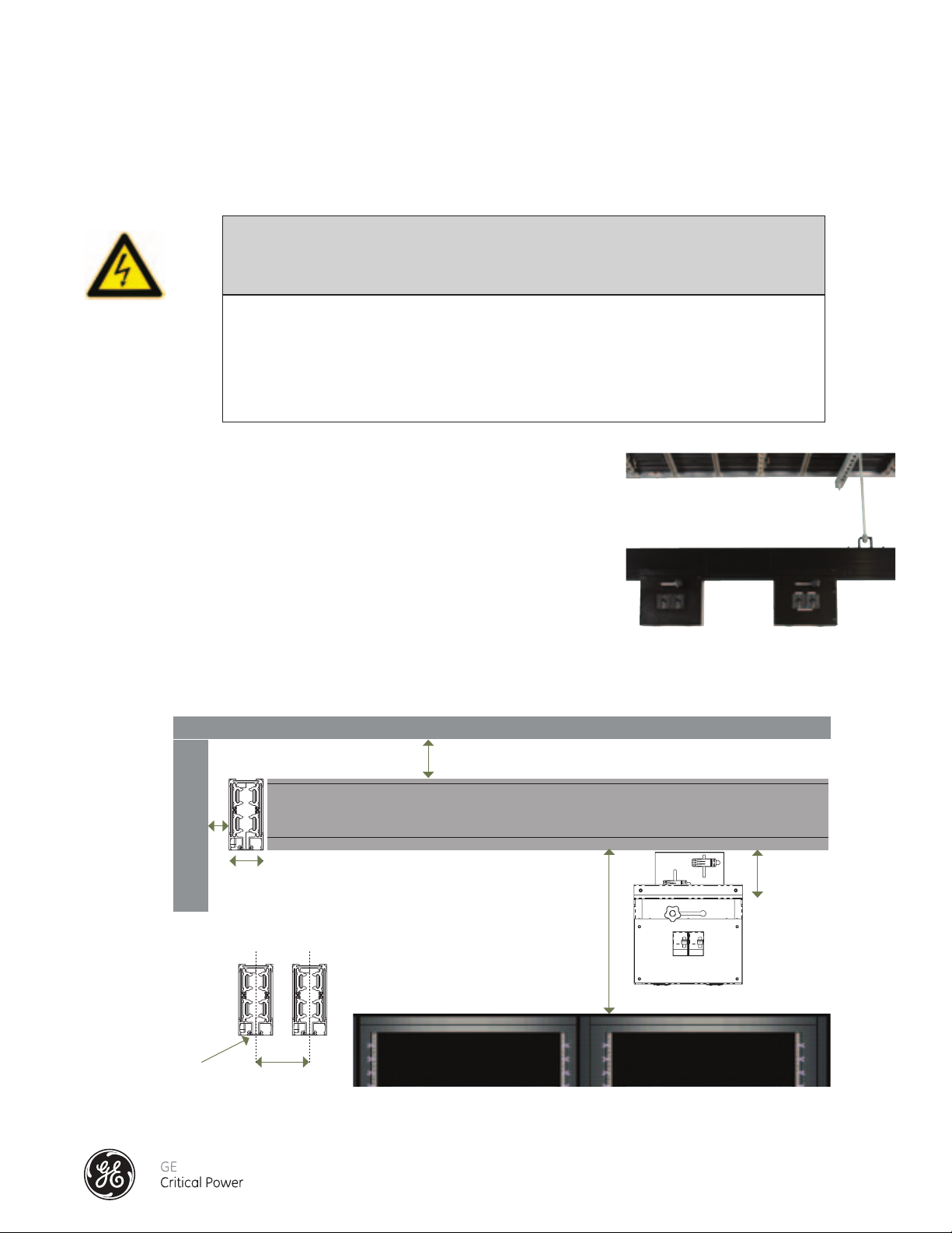
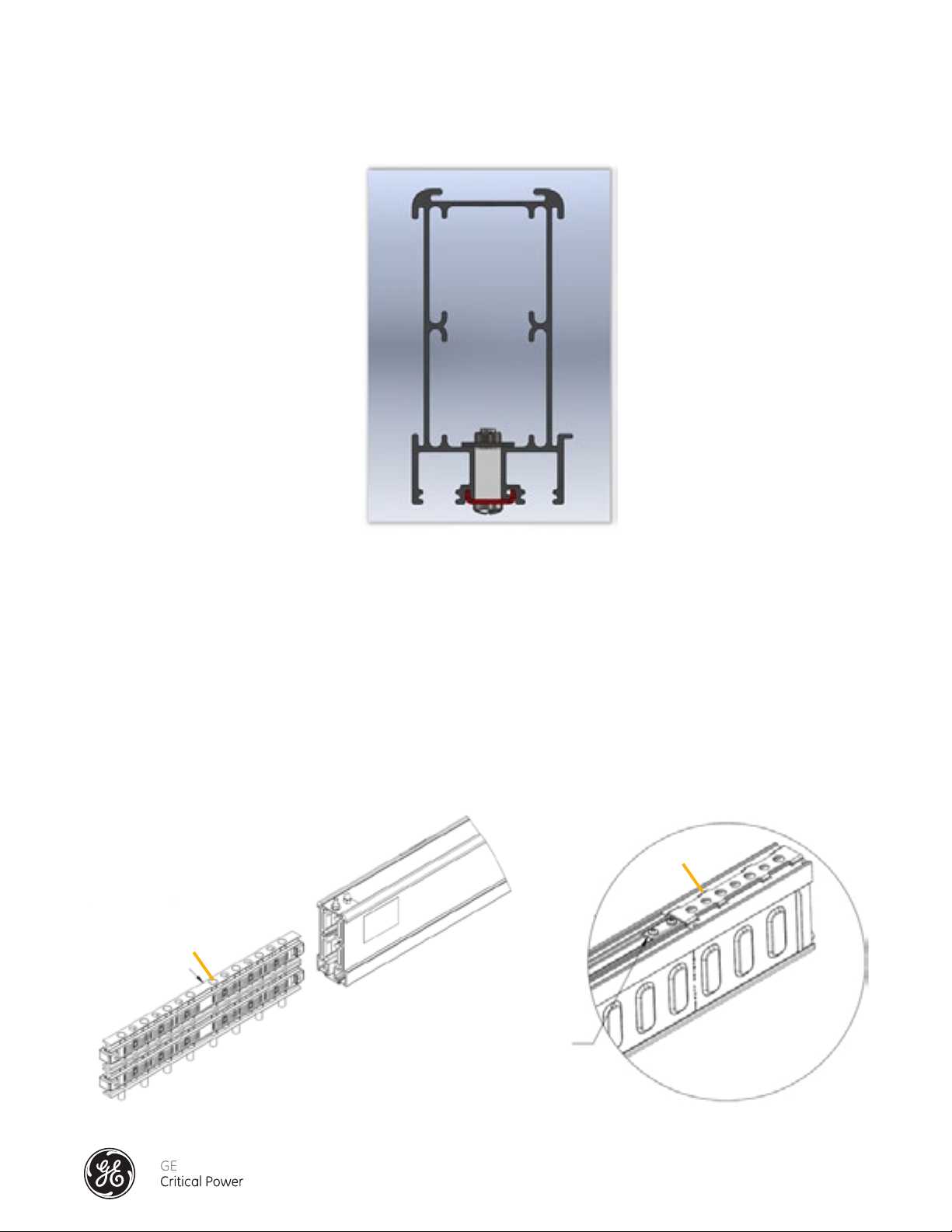
VERTICAL BUSWAY INSTALLATION
See Figure 1. For busways installed vertically with channel opening down,
always maintain:
A minimum clearance distance of 6 inches (153 mm) from the top of the
busways to the ceiling and 1 inch (26mm) from the wall.
Parallel runs for two systems mounted in the same area shall have the following
clearances between the systems.
A minimum clearance distance of 6 inches (153 mm) from the center-point of
busway run A to the next run B.
ceiling
6"
wall
1"
2.5"
bus rail A
underside of busway
bus rail B
18" minimum
Top of Server Cabinet
or Equipment
5"
underside of busway
6"
Figure 1 - Vertical Busway Installation
Installation & Operation Manual, GE Series DPB Busway
March 25, 2013, Rev 0
GE Confidential
6
Page 15
Series DPB Busway Installation & Operation Manual
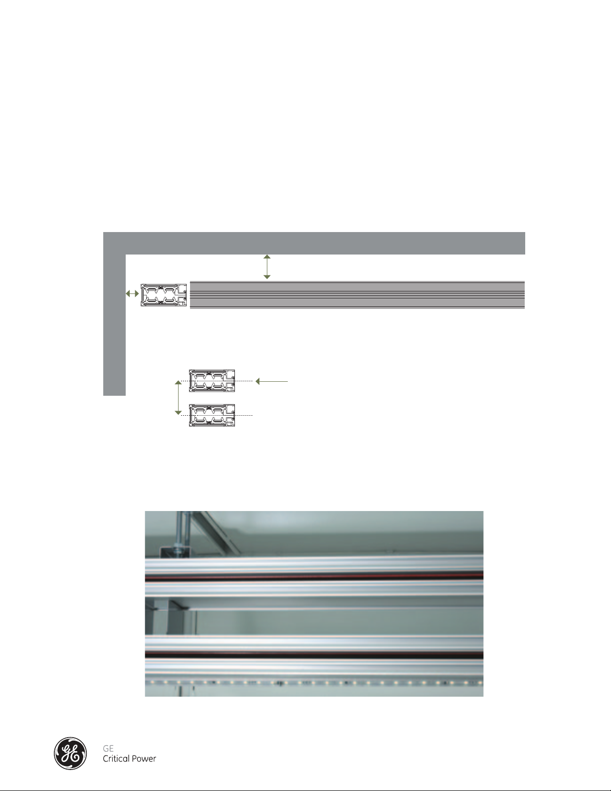
HORIZONTAL BUSWAY INSTALLATION
See Figure 2. For busways installed flat wise or horizontally, maintain the following clearances.
A minimum clearance of 6 inches (153mm) from top of bus to ceiling.
A minimum clearance distance of 1 inch (26 mm) from the back of the busways to the edge of the wall.
A minimum clearance distance of 6 inches (153 mm) from the center-point of one busway run to
the next when mounted in a stacked configuration, one above the other.
ceiling
6"
1.0"
underside of busway
wall
bus rail A
Tap Off box insertion
6"
bus rail B
Figure 2 - Horizontal Busway Installation
Example A/B Horizontal Busway Installation
Installation & Operation Manual, GE Series DPB Busway
March 25, 2013, Rev 0
GE Confidential
7
Page 16

Series DPB Busway Installation & Operation Manual
BUSWAY SYSTEM MOUNTING
SPECIFIED AND SAFE OPERATION OF THE SERIES DPB BUSWAY IS DEPENDENT ON ITS
PROPER INSTALLATION. MISALIGNMENT OF THE BUSWAY COMPONENTS, (END FEEDS,
BUS RAILS, AND SPLICES) WILL COMPROMISE ITS PERFORMANCE.
1) End Feed enclosures must be securely mounted so that they are completely level (side-to-side and front-to-back).
2) Bus Rails must be securely installed so that they are level and completely aligned to the End Feed enclosures and with
adjoining Bus Rail sections.
3) When each Busway run is properly supported / mounted, leveled , and aligned, all Splices must be verified to be
"un-cammed" (not actuated with Cam Actuator Tool).
4) The Splice units must be able to move freely and fully into both sections of adjoining sections of bus before the Splices can
be "cammed" (actuated).
5) Once the free movement of the Splice units is verified, the Splice can be actuated. The installation of Dowel Pins completes
the correct installation of the Splices.
Installation & Operation Manual, GE Series DPB Busway
March 25, 2013, Rev 0
GE Confidential
8
Page 17
Series DPB Busway Installation & Operation Manual
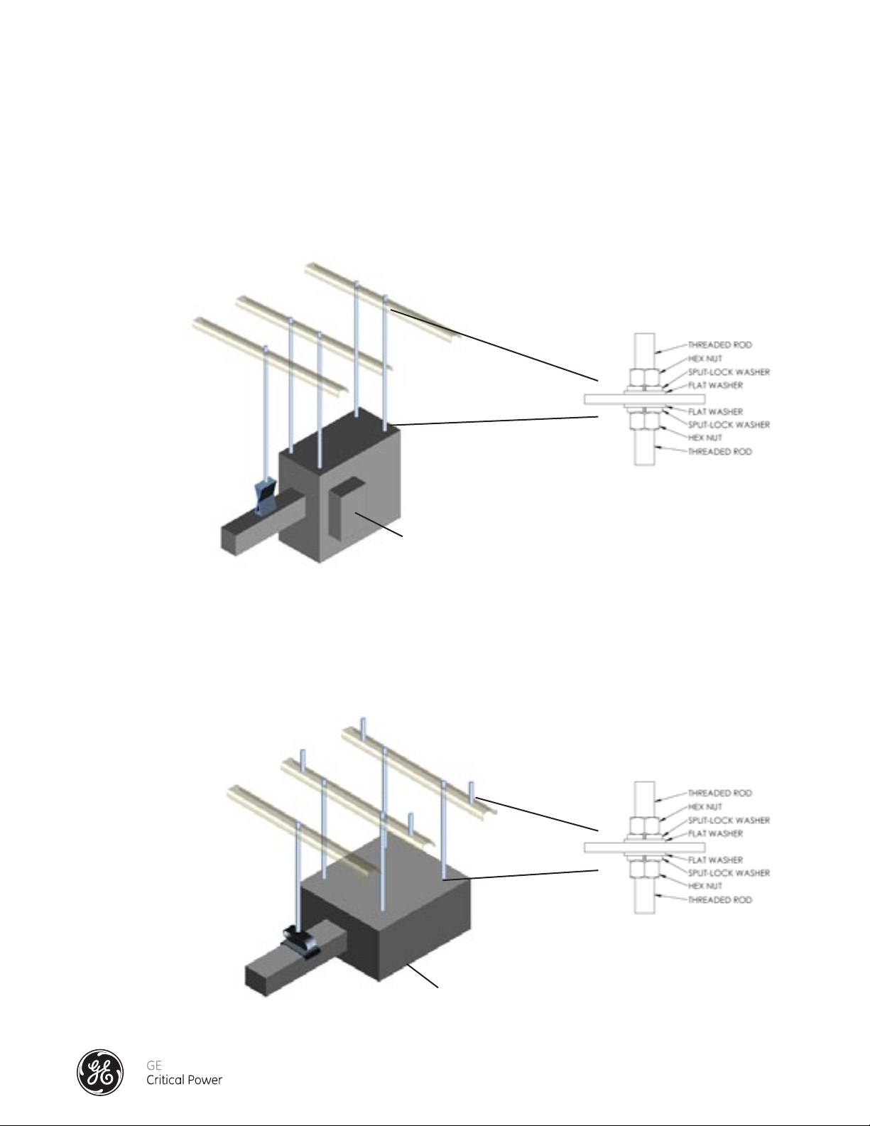
MOUNTING THE END FEED
VERTICAL END FEED SUPPORT
Series DPB End Feed enclosures can be mounted in a number of ways. The recommended method for mounting Series DPB
End Feed enclosures is as shown in Figure 3. Four 3/8" threaded rods (see Figure 3A) secure the enclosure to the ceiling or to
UnistrutTM, and a standard busway hanger supports the Splice Extension. These need to be aligned and leveled to each other
so that the End Feed is completely level after installation.
UNISTRUT
TM
Figure 3A
THREADED ROD
END FEED
VERTICAL BUSRAIL HANGER
END FEED OR
CEILING / UNISTRUT
TM
OPTIONAL BCMS
MONITORING MODULE
Figure 3 - Vertical End Feed Support
HORIZONTAL END FEED SUPPORT
Series DPB End Feed enclosures can be horizontally mounted. The recommended method is similar to the vertical mounting
method and is shown in Figure 4 below. The enclosure is supported by four 3/8" threaded rods (see Figure 4A) secure the
enclosure to the ceiling or to UnistrutTM, and a standard busway hanger supports the Splice Extension. These need to be
aligned and leveled to each other so that the End Feed is completely level after installation.
UNISTRUT
TM
HORIZONTAL BUSRAIL HANGER
THREADED ROD
END FEED
OPTIONAL BCMS
MONITORING MODULE
ON BOTTOM OF END FEED
Figure 4 - Horizontal End Feed Support
Installation & Operation Manual, GE Series DPB Busway
March 25, 2013, Rev 0
Figure 4A
END FEED OR
CEILING / UNISTRUT
GE Confidential
TM
9
Page 18
Series DPB Busway Installation & Operation Manual
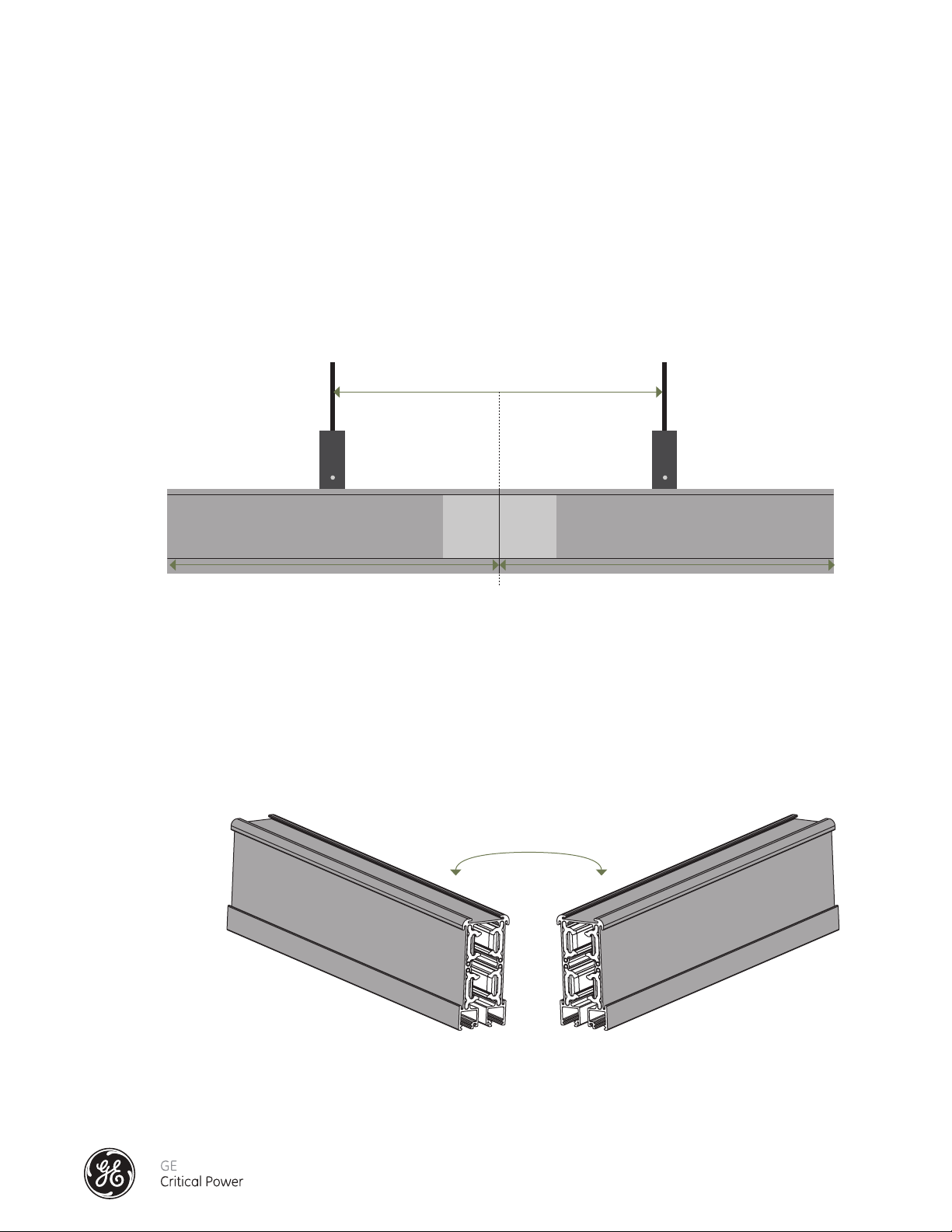
MOUNTING THE BUSRAIL
SUPPORT
When mounting the bus rail please use the supplied hangers that are designed to fit into the top and or side channels found
on each section of bus rail. Each section of bus rail should have at least one hanger and threaded rod assembly with the
maximum span being 5' on centers. 10' and 12' bus rail sections should have a minimum of two hanger and threaded rod
assemblies. Bus Rail lengths longer than 12' should have a minimum of three hangers and threaded rod assemblies. The
span of the hanger and threaded support at a Splice point should be a maximum of 6' on center. Each section of bus rail
needs to be aligned and level. See Figure 5.
Threaded Rod and
Hanger Assembly
6'
X
Figure 5 - Busrail Mounting Support around Splice Point
NEUTRALS ALIGNMENT
Our busway system is designed so that it is NOT possible to mount the busways if the neutral conductor is not in phase with
one another from section to section. The neutral conductor of each element MUST be aligned on the same side of the system. Clear markings are also made on the busway system to ensure proper phasing. See Figure 6.
Threaded Rod and
Hanger Assembly
X
X = 10' to 12'
neutral to neutral
neutral
NA
Figure 6 - Busrail Neutrals Alignment
Installation & Operation Manual, GE Series DPB Busway
March 25, 2013, Rev 0
A
C
CB
neutral
N
B
GE Confidential
10
Page 19

Series DPB Busway Installation & Operation Manual
INSTALLATION OF THE SPLICE CONNECTOR – 160 - 250 AMP
All busway sections are shipped from the factory with one splice pack assembly. As each busway section is
mounted on its hanger supports, the abutting end of the splice section can be installed to
the adjoining busway section.
Connection of Busway Sections and Fittings: (See Figure 7)
1) Each section of busway will come with one Splice Pack assembly (D) and two "E" Clips (E) one at each
end of the bus section. Make sure the “E” Clips are always installed on each end of each rail.
2) Bus sections are phase-keyed to maintain proper circuit phasing of the run.
3) Section 2 (with the splice) and Section 1 (without splice) will be aligned on their respective supports. Slide
Section 1 forward on the splice pack.
4) Slide Splice Joint Covers (B & C) and "E" Clip (E) into place positioning them equally across the bus.
5) Slide Grounding Plate (A) into place and secure the four grounding screws to the busway.
Torque values for the set screws is 60 in-lbs minimum and a maximum of 85 in-lbs.
6) Slide the Splice Pack Assembly so that it is positioned equally on either side of the bus section joint.
Allen-head screws
1 2
A Top Grounding Plate with set screws
E E
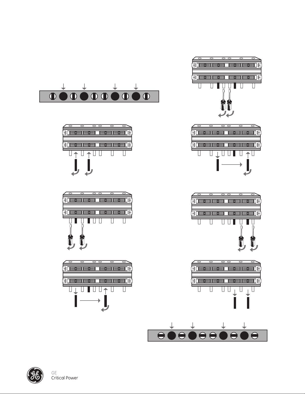
7) Starting from one end of the Splice Pack (Figure 8), only use the steel cam-actuator tools supplied to
expand the splice joint contact assemblies into contact with bus sections bus bars.
i) Insert one tool into the first cam port #1; the second cam-actuator tool into the adjacent cam port
#2. Rotate each tool ¼ turn to expand the contact plates.
ii) Rotate the adjacent, non-metallic cam spacers (a & b), ¼ turn to hold the expanded contact plate
in place. DO NOT ATTEMPT TO USE THE NON-METALLIC CAMSPACERS TO EXPAND THE CONTACT
PLATE ASSEMBLIES.
iii) Rotate and remove the cam actuator tool in cam port #1, and insert it into cam port #3. Rotate the
steel tool in cam port #3, 1/4 turn clockwise to expand the contact plates.
iv) Rotate the adjacent, non-metallic cam spacers (c & d), 1/4 turn clockwise.
v) Rotate and remove the cam actuator tool in cam port #2, and insert it into cam port #4. Rotate the
steel tool in cam port #4 to expand the contact plates.
vi) Rotate the adjacent, non-metallic cam spacers (e & f), 1/4 turn clockwise.
vii) Rotate and remove the cam actuator tools.
B Side Cover Support Plate
C Side Cover Support Plate
D Splice Pack Assembly
E “E” clip
Figure 7 - Splice Installation Overview 160 - 250 Amp
B
A
D
C
1 Bus Section
2 Bus Section
Splice Pack
Installation & Operation Manual, GE Series DPB Busway
March 25, 2013, Rev 0
GE Confidential
11
Page 20
Series DPB Busway Installation & Operation Manual
a
b
cd
ef
a
Cam
Port #1
Cam Spacers
Cam
Port #2
b
cd
ef
Cam
Port #3
Cam
Port #4
12 34
rotate Spacers
c & d
rotate Spacers e & f
move from
Cam 2 to Cam 4
a
Cam
Port #1
Cam Spacers
Cam
Port #2
b
cd
cd
ef
ef
Cam
Port #3
Cam
Port #4
a
Cam
Port #1
Cam Spacers
Cam
Port #2
bcde f
Cam
Port #3
Cam
Port #4
1/4 turn
clockwise
1/4 turn
clockwise
1/4 turn
clockwise
12 34
12 34
Figure 8 - Splice Installation Detail 160 - 250 Amp
cd
Step 4
Cam
bottom view
Port #1
12 34
Cam
Port #2
Step 1
1/4 turn
clockwise
1/4 turn
clockwise
ab
Step 2
Cam
Port #3
Cam
Port #4
cam spacer alignment before installation
insert tool into
Cam 1 & 2
Step 5
Step 6
1/4 turn
clockwise
move from
Cam 2 to Cam 4
rotate Spacers
c & d
1/4 turn
clockwise
1/4 turn
clockwise
ef
1/4 turn
clockwise
1/4 turn
clockwise
Step 3
1/4 turn clockwise
rotate Spacers a & b
move from
Cam 1 to Cam 3
rotate Spacers e & f
1/4 turn clockwise 1/4 turn clockwise
Step 7
remove Cam tools
Cam
Port #1
Cam
Port #2
Cam
Port #3
Cam
Port #4
12 34
a
cam spacer position - splice installation complete as seen from bottom
bcde f
Installation & Operation Manual, GE Series DPB Busway
March 25, 2013, Rev 0
GE Confidential
12
Page 21
Series DPB Busway Installation & Operation Manual
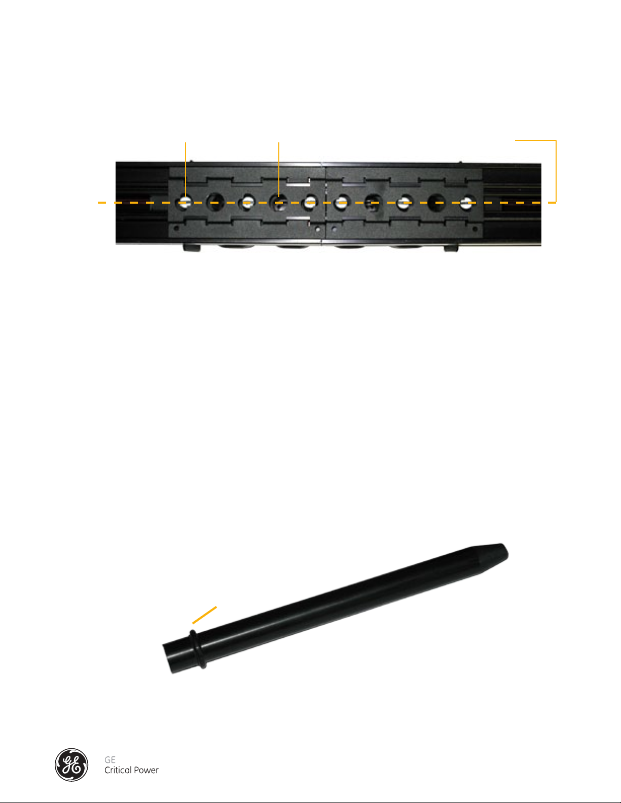
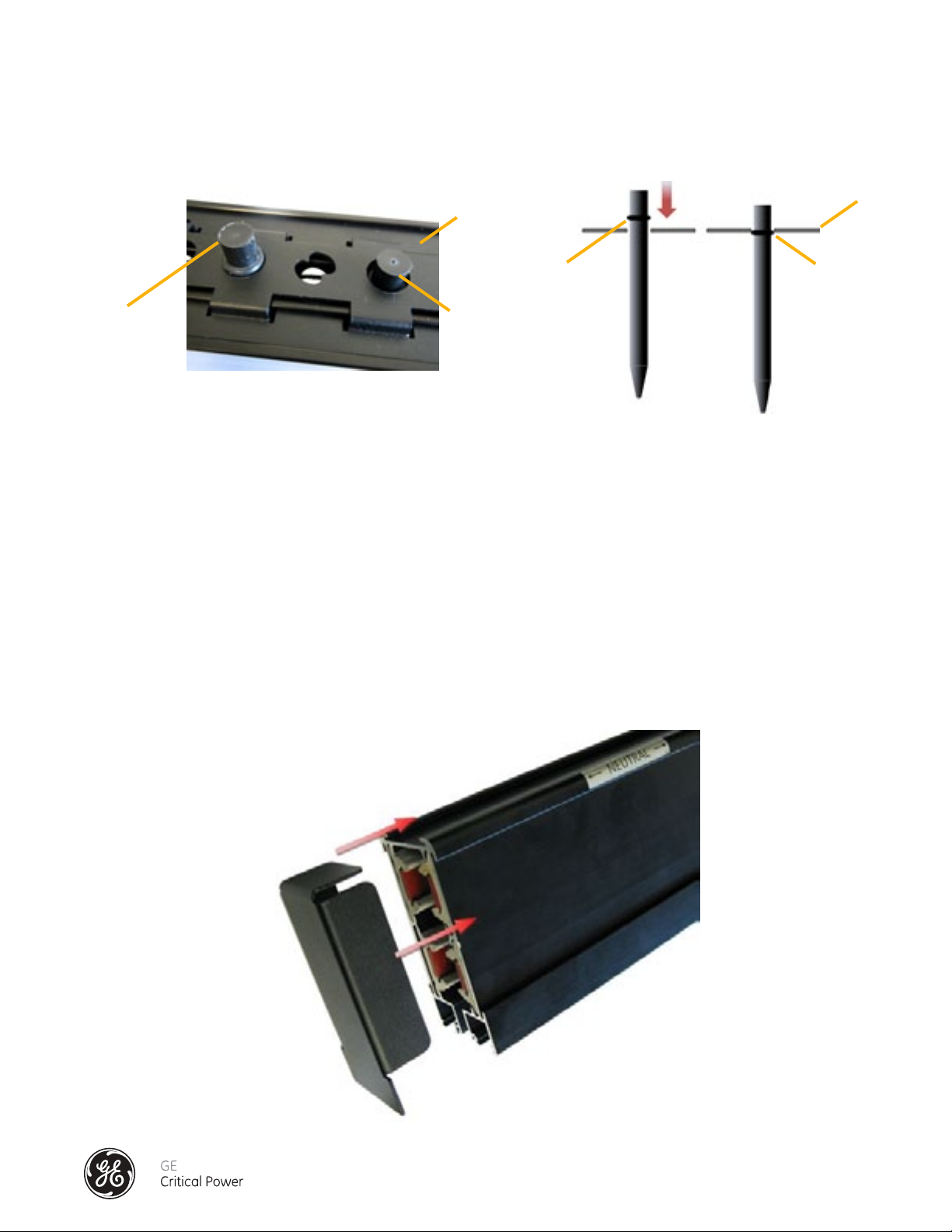
8.) CAUTION: DO NOT proceed to 9) Installation of the Dowel Pin Devices until the Cam Spacers are
verified to be in the locked position. A properly installed Splice, when viewed from the bottom (open
channel) of the joined bus sections will show the Cam Spacers in the Locked Position as show in
Figure 8.1 below.
Cam Spacer Cam Actuator Tool Port
Cams in Locked Position
Figure 8.1 - Cam Spacers in Locked Position
9.) Installation Of The Dowel Pin Devices
The Dowel Pins are used to secure open Cam Actuator Tool ports and add Cam Spacer functionality.
Material Required for Initial Installation (before busway is energized*):
Four Dowel Pin Devices
10) Inspect the busway, and verify that the splice connections of the busway have been installed correctly
per INSTALLATION OF THE SPLICE CONNECTOR – 160 to 250 AMP.
1. Verify no gaps between the bus connections
2. Verify the E-clips are positioned properly.
3. Verify the Cam Spacers (white-tipped, slotted lock pins) are positioned properly.
*please contact factory service for dowel pin installation procedure when working on an energized
busway (800-225-4838)
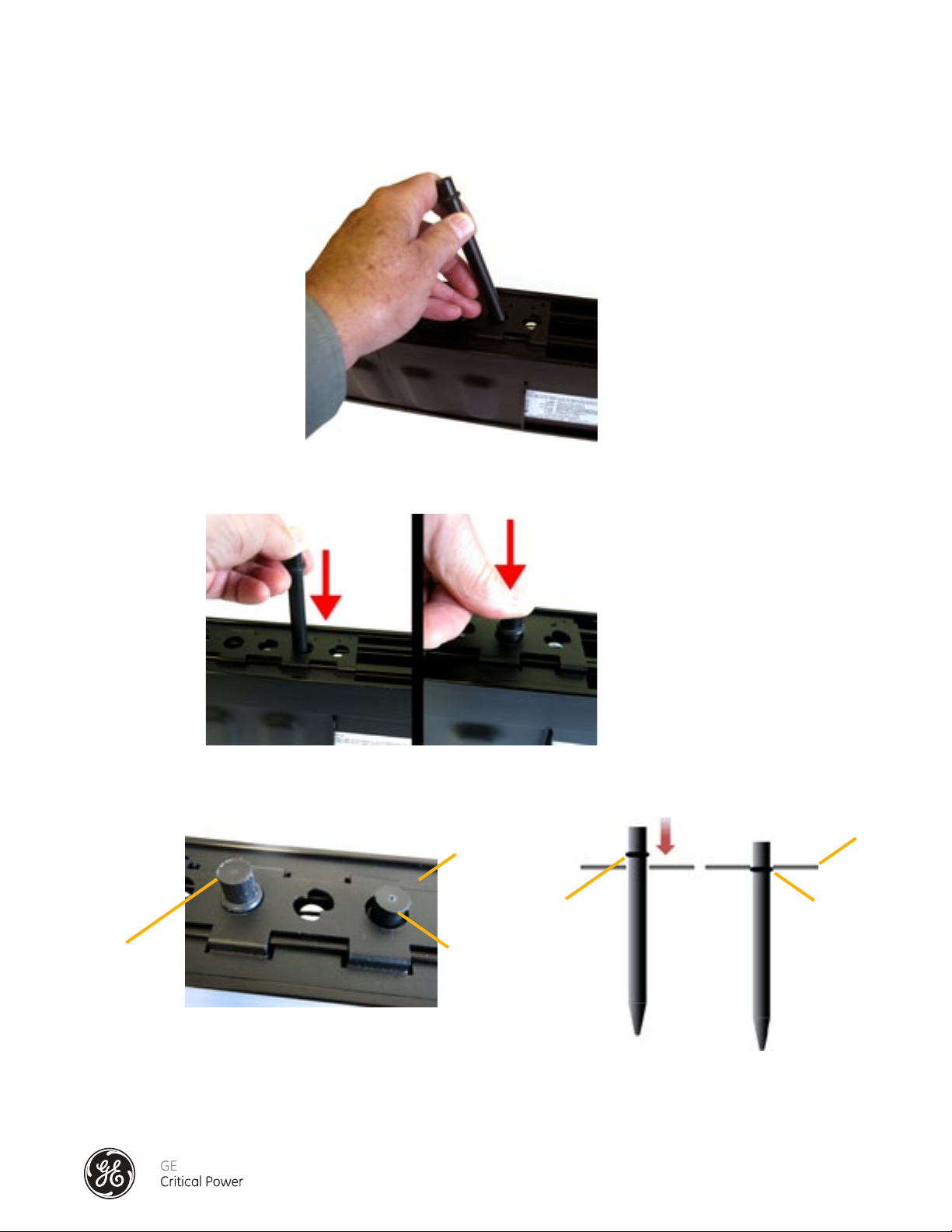
11.) Each Dowel Pin has an O-ring set into a small groove on the insertion end of the dowel pin.
(See Figure 8.2).
O-Ring
Figure 8.2 - Dowel Pin
Installation & Operation Manual, GE Series DPB Busway
March 25, 2013, Rev 0
GE Confidential
13
Page 22
Series DPB Busway Installation & Operation Manual
12.) Position the Dowel Pin into the round port between the first pair (viewed left-to-right, or right-to-left) of
installed white-tipped, slotted Cam Spacers. The conical pointed end is inserted first, and the end with
the O-ring inserted last. (See Figure 8.3)
Figure 8.3 - Positioning of Dowel Pins
13.) Using pressure push the Dowel Pin so that it is inserted completely into the Cam Actuator Tool Hole.
(See Figure 8.4)
Figure 8.4 - Insertion of Dowel Pin
14.) Make sure that the O-ring on the dowel is inside the E-clip. (See Figure 8.5)
E Clip
Before
Before
After
Figure 8.5 - Dowel Pin O-Ring Inside "E" Clip
15.) Repeat Step 13 until all four (4) vacant Cam-Actuator Tool Ports have Dowel Pins in them.
16.) Repeat the process for each splice in the bus run until complete.
E Clip
After
Installation & Operation Manual, GE Series DPB Busway
March 25, 2013, Rev 0
GE Confidential
14
Page 23
Series DPB Busway Installation & Operation Manual
INSTALLATION OF OPTIONAL "C-CLIPS" FOR 35kAIC RATED 400A BUSWAY
The 35 kAIC rated 400A Busway utilizes a C-Clip to control tolerances in the busrail channel opening. Detailed below are the
modified installation instructions to install these C-Clips on End Feeds and Busrails.
END FEED C-CLIP INSTALLATION
See Figure 9 - End Feed C-Clip Installation - 400 Amp
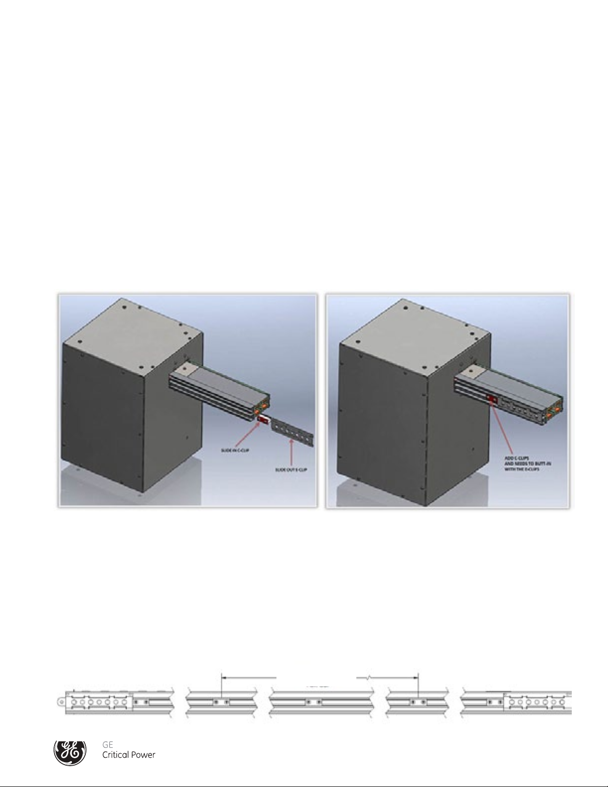
1.) Locate the C-clip
2.) Remove E-clip by sliding it off the bus rail of the End Feed
3.) Install the C-clip by sliding into place between the walls of the open channel.
4.) Reinstall the E-clip.
5.) Position C-clip so that that it butts up against the E-clip.
6.) Tighten screws on C-clip.
NOTE: Loosen, do not remove, the two screws of the C-clip assembly.
Figure 9 - End Feed C-clip Installation - 400 Amp
BUSRAIL AND SPLICE JOINT C-CLIP INSTALLATION
Install C-clips at the prescribed locations on the bus rail. (See Figure 10 - Busrail C-Clip Installation - 400 Amp).
1.) A C-clip should be placed approximately every 31.5" along the busrail or 2 x 31.5" (63") Pitch Location For Clip. If Tap Off
Boxes are installed in the busrail and meet the 31.5" requirement then a C-clip is not required. If a 31.5" opening exists along
the busrail then a C-clip will need to be installed.
NOTE: Loosen, do not remove, the two screws of the C-clip assembly.
2x31.5" (63")
Pitch Location For Clip
Figure 10 - Busrail C-Clip Installation - 400 Amp
Installation & Operation Manual, GE Series DPB Busway
March 25, 2013, Rev 0
GE Confidential
15
Page 24
Series DPB Busway Installation & Operation Manual
2.) Slide the C-clip into bus rail positioning the C-clip as shown in (Figure 11 - Busrail C-Clip Profile View - 400 Amp). NOTE: Do
not tighten the screws yet.
Figure 11 - Busrail C-Clip Profile View - 400 Amp
3.) Position a Splice Connector into the bus rail that has been properly mounted and supported (leveled, aligned).
NOTE: When the busway is mounted horizontally, make sure the Cam Spacers are flush with the top of the Splice Connector
before positioning the assembly. (See Figure 12 - Cam Spacers)
4.) Bring the ends of busrails to be spliced together, position the Splice Pack equally across the joint, position the E-clips, Side
Support Plates, and Grounding plate ready for Splice cam actuation. (See Figure 13 - Busrail C-Clip Splice and E-Clip Location - 400 Amp).
5.) Install the Splice per section "INSTALLATION OF THE SPLICE CONNECTOR - 400 AMP".
6.) Position and tighten the two screws of each C-clip.
E-clip
Cam Spacer
Figure 12 - Busrail Cam Spacers
Installation & Operation Manual, GE Series DPB Busway
March 25, 2013, Rev 0
C-clip
Figure 13 - Busrail C-Clip Splice and E-Clip Location - 400 Amp
GE Confidential
16
Page 25

Series DPB Busway Installation & Operation Manual
INSTALLATION OF THE SPLICE CONNECTOR – 400 AMP
All busway sections will come from the factory with one splice connection.
As the busways section is mounted on its hanger supports, the abutting end of the splice section can be
installed to the adjoin busway section.
Connection of Busway Sections and Fittings: (See Figure 14)
1) Each section of busway will come with one Splice Pack assembly (D) and two "E" Clips (E) one at each
end of the bus section. Make sure the “E” Clips are always installed on each end of each rail.
2) Bus sections are phase-keyed to maintain proper circuit phasing of the run.
3) Section 2 (with the splice) and Section 1 (without splice) will be aligned on their respective supports.
Slide Section 1 forward on the splice pack.
4) Slide Splice Joint Covers (B & C) and "E" Clip (E) into place positioning them equally across the bus.
5) Slide Grounding Plate (A) into place and secure the four grounding screws to the busway. Tighten each
nut to a torque value of 85 in-lbs.
6) Slide the Splice Pack Assembly so that it is positioned equally on either side of the bus section joint.
Grounding Stud Nut
diagram 7
A
B
D
Splice Pack
C
A Top Grounding Plate
E E
7) See Figure 8 for Splice Installation reference. Starting from one end of the Splice Pack (Figure 15),
only use the steel cam-actuator tools supplied to expand the splice joint contact assemblies into
contact with bus sections bus bars.
i) Insert one tool into the first cam port #1; the second cam-actuator tool into the adjacent cam port
#2. Rotate each tool ¼ turn to expand the contact plates.
ii) Rotate the adjacent, non-metallic cam spacers (a & b), ¼ turn to hold the expanded contact plate
in place. DO NOT ATTEMPT TO USE THE NON-METALLIC CAMSPACERS TO EXPAND THE CONTACT
PLATE ASSEMBLIES.
iii) Rotate and remove the cam actuator tool in cam port #1, and insert it into cam port #3. Rotate the
steel tool in cam port #3, ¼ turn to expand the contact plates.
iv) Rotate the adjacent, non-metallic cam spacers (c & d), ¼ turn.
v) Rotate and remove the cam actuator tool in cam port #2, and insert it into cam port #4. Rotate
and remove the cam actuator tool in cam port #3, and insert it into cam port #5. Rotate the steel
tools in cam ports #4 and #5 to expand the contact plates.
vi) Rotate the adjacent, non-metallic cam spacers (e & f), ¼ turn.
B Side Cover Support Plate
C Side Cover Support Plate
D Splice Pack Assembly
E “E” clip
Figure 14 - Splice Installation Overview - 400 Amp
1 Bus Section
2 Bus Section
Installation & Operation Manual, GE Series DPB Busway
March 25, 2013, Rev 0
GE Confidential
17
Page 26

Series DPB Busway Installation & Operation Manual
Cam
Cam
Cam
Cam
Cam
Cam
a
Cam
Port #1
Cam Spacers
bottom view
Cam
Port #2
bcdefgh
Cam
Port #3
Cam
Port #4
Cam
Port #5
Cam
Port #6
123 456
vii) Rotate and remove the cam actuator tool in cam port #4, and insert it into cam port #6. Rotate the
steel tool in cam port #6 to expand the contact plates.
viii) Rotate the adjacent, non-metallic cam spacers (g & h), ¼ turn.
ix) Rotate and remove the cam actuator tools.
Port #1
123 456
a
bottom view
Cam
Port #1
123 456
a
Port #2
Port #3
Port #4
Port #5
Port #6
bcdefgh
cam spacer alignment before installation
Cam
Port #2
Cam
Port #3
Cam
Port #4
Cam
Port #5
Cam
Port #6
bcdefgh
cam spacer position - splice installation complete as seen from bottom
Figure 15 - Splice Installation Detail 400 Amp
8.) CAUTION: DO NOT proceed to 9) Installation of the Dowel Pin Devices until the Cam Spacers are
verified to be in the locked position. A properly installed Splice, when viewed from the bottom (open
channel) of the joined bus sections will show the Cam Spacers in the Locked Position as show in Figure
15.1 below.
Cam Spacer Cam Actuator Tool Hole
Cams in Locked Position
Figure 15.1 - Cam Spacers in Locked Position
9.) Installation Of The Dowel Pin Devices
The Dowel Pins are used to secure open Cam Actuator Tool ports and add Cam Spacer functionality.
Material Required for Initial Installation (before busway is energized*):
10) Inspect the busway, and verify that the splice connections of the busway have been installed correctly
Six Dowel Pin Devices
per INSTALLATION OF THE SPLICE CONNECTOR – 400 AMP.
1. Verify no gaps between the bus connections
2. Verify the E-clips are positioned properly.
3. Verify the Cam Spacers (white-tipped, slotted lock pins) are positioned properly.
* please contact factory service for dowel pin installation procedure when working on an energized
busway (800-225-4838)
Installation & Operation Manual, GE Series DPB Busway
March 25, 2013, Rev 0
GE Confidential
18
Page 27

Series DPB Busway Installation & Operation Manual
11.) Each Dowel Pin has an O-ring set into a small groove on the insertion end of the dowel pin.
(See Figure 15.2).
O-Ring
Figure 15.2 - Dowel Pin
12.) Position the Dowel Pin into the round port between the first pair (viewed left-to-right, or right-to-left) of
installed white-tipped, slotted Cam Spacers. The conical pointed end is inserted first, and the end with
the O-ring inserted last. (See Figure 15.3)
Figure 15.3 - Positioning of Dowel Pins
13.) Using pressure push the Dowel Pin so that it is inserted completely into the Cam Actuator Tool Hole.
(See Figure 15.4)
Figure 15.4 - Insertion of Dowel Pin
Installation & Operation Manual, GE Series DPB Busway
March 25, 2013, Rev 0
GE Confidential
19
Page 28
Series DPB Busway Installation & Operation Manual
14.) Insert another Dowel into the next empty port on the splice. (Six empty tool ports per 400A splice
connection). Make sure that the O-ring on the dowel is inside the black bracket (E-clip) (See Figure 15.5)
E Clip
Before
Before
After
Figure 15.5 - Dowel Pin O-Ring Inside "E" Clip
15.) Repeat Step 13 until all the vacant Cam-Actuator Tool ports have Dowel Pins in them.
16.) Repeat the process for each splice in the bus run until complete.
16) Repeat the process for each splice in the bus run until complete.
INSTALLATION OF THE END CAP CLOSURE PLATE
Always terminate each busway run with an end cap in order to prevent any contact with live
conductors or internal components inside the extruded aluminum busrail housing. See Figure 16.
E Clip
After
To install, align side and top tabs with channels on busrail and tap in using a rubber mallet until flush.
The method of installation of the end caps is common for all mounting positions.
Figure 16 - Busrail End Cap Installation
Installation & Operation Manual, GE Series DPB Busway
March 25, 2013, Rev 0
GE Confidential
20
Page 29
Series DPB Busway Installation & Operation Manual
CABLE TERMINATIONS TO THE END FEED BOX
STANDARD END FEED
Run all conduit fittings and supports;
attach cable to the listed lugs on the
termination pad.
Ensure that phasing is correct
(see Figure 17).
Once complete, torque all connections
with a torque wrench to the values
specified on the label located inside the
End Feed Box.
ØC
N
ØA
ØB
GROUND
Figure 17 - Standard End Feed Cable Terminations
BRANCH CIRCUIT MONITORING (BCMS)
END FEED
Run all conduit fittings and supports;
attach cable to the listed lugs on the
termination pad.
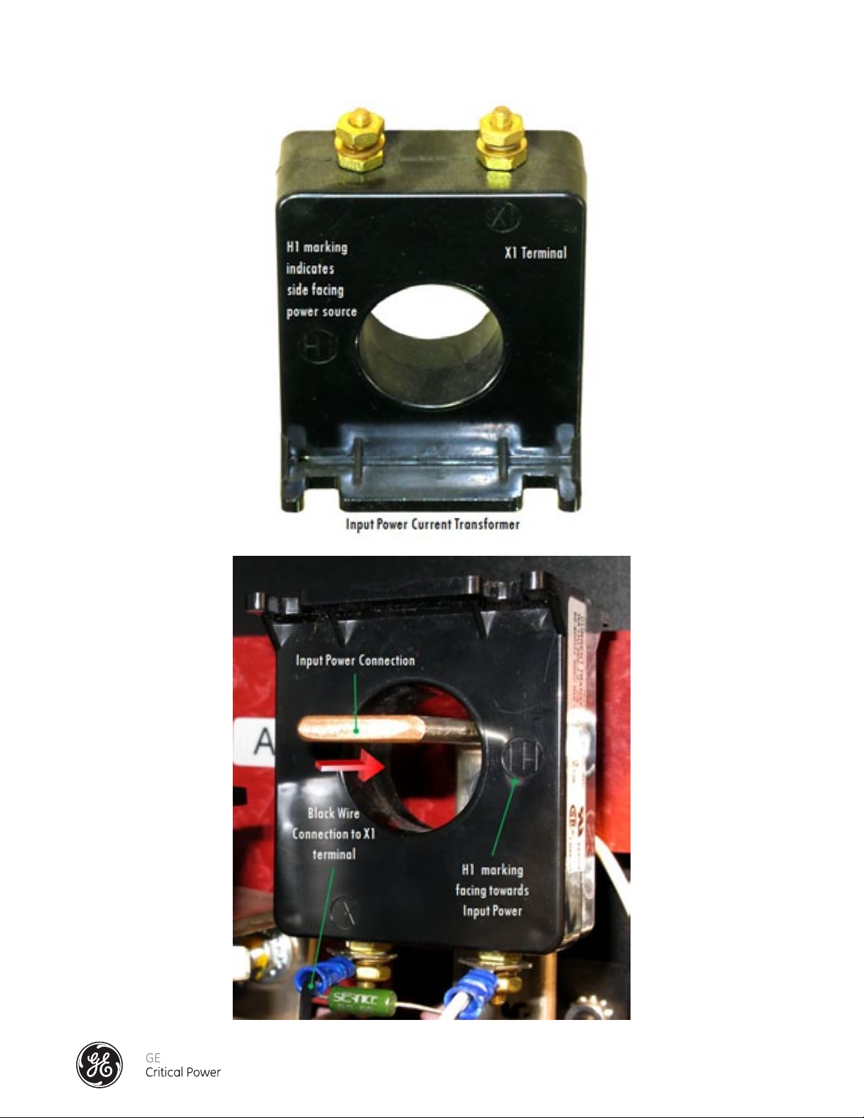
Ensure that phasing is correct (see Figure
18) and that Current Transformers (CT)
are facing in the correct direction (see
Figure 19). The H1 notation on the CT
should be facing the input power source.
Once complete, torque all connections
with a torque wrench to the values
specified on the label on the End Feed Box.
N
ØA
ØB
ØC
CT
GROUND
Figure 18 - Branch Circuit Monitoring (BCMS) End Feed Cable Terminations
Installation & Operation Manual, GE Series DPB Busway
March 25, 2013, Rev 0
GE Confidential
21
Page 30
Series DPB Busway Installation & Operation Manual
Figure 19 - End Feed Current Transformer (CT) Orientation
Installation & Operation Manual, GE Series DPB Busway
March 25, 2013, Rev 0
GE Confidential
22
Page 31

Series DPB Busway Installation & Operation Manual
TAP OFF BOX INSTALLATION
INSTALLATION WARNING
Depending on the installation orientation of the busways, the following WARNING should always be exercised when
mounting and energizing the Tap Off Boxes:
CAUTION
HAZARD OF EQUIPMENT DAMAGE
Always maintain the minimum required clearance distance as shown below.
Ensure sufcient clearance for the doors of the Tap Off Units to open or close without obstruction
Ensure sufcient access to the switch or circuit breaker of the tap off units
Failure to follow these instructions may result in equipment damage or personal injury.
Installation & Operation Manual, GE Series DPB Busway
March 25, 2013, Rev 0
GE Confidential
23
Page 32

Series DPB Busway Installation & Operation Manual
TAP OFF BOX MOUNTING
Busway Tap Off Boxes have cam-actuated connections to the busway system as shown in Figure 20. As a safety feature
the insertion of the Tap Off Box cannot be made into the busway system if the cam knob is in the ON position and the tap off
contacts are extended. In the same way a Tap Off Box cannot be removed from the busway system while it is in the ON
position. The contacts will not pass through the opening until fully retracted and the bus insulation will keep the contacts
from passing through the bus until they are fully disengaged and closed. As a further safety feature the contacts are spring
activated to the OFF position to ensure that they fully retract.
Contacts
Cam Knob
Tap Off
Box
CAM OFF
Tap Off
Box
CAM ON
isolated ground connection (optional)
Cam Knob
Contacts
Retracted
Contacts
Contacts
Extended
TOP VIEW
OFF
Figure 20 - Tap Off Box Connections
Insertion and phase control are part of the safety built into every Tap Off Box. A lip is designed into the busrail that will
not allow the Tap Off Box to be inserted backwards. The Tap Off Box is inserted to the busway as shown in Figure 21. The
ground connection will be made and the phasing will be aligned in step 3 when the Tap Off Box is fully seated against the
busrail, and hold-down screws are screwed in over top of the side channel lip. NOTE: Do not tighten the hold down screws
so that they penetrate the busrail. To enegize the Tap Off Box, slide the cam knob to the ON position engaging the Contacts
to the bus Phasing and Neutral bus bars. As a safety feature the ground connection is always made first.
TOP VIEW
ON
STEP 1 STEP 2 STEP 3
neutral neutral neutral neutral
OFF
OFF
OFF
Figure 21 - Tap Off Box Mounting and Energizing
Installation & Operation Manual, GE Series DPB Busway
March 25, 2013, Rev 0
HOLD DOWN SCREWS
GE Confidential
STEP 4
ON
CAM KNOB
24
Page 33

Series DPB Busway Installation & Operation Manual
BEFORE ENERGIZING THE BUSWAY CHECKLIST
Before energizing the busway, some precautionary inspections and reviews are necessary.
1. Perform a complete visual inspection of all end feed connections (See Figure 12 (Standard) and
13 (BCMS)), splice couplings (See Figure 8 (160-250A) and Figure 10 (400A)) and tap off boxes
(See Figure 16).
2. Ensure that all protective devices are correctly rated with respect to the loads supplied,
or in accordance with project specifications, and that they are in the OFF position.
3. Check that all the Tap Off Boxes protective devices are in the OFF position.
4. Conduct a Resistance Test between A: busrail-to-busrail assembly, and B: busrail-to-tap off box.
A: Value shall be < 0.005 ohms
B: Value shall be < 0.006 ohms
5. Check the grounding connections of all devices are secure and tightened. Note: A Torque
Specification label can be found inside each End Feed.
Lug Torque (End Feed) Record: ______________________
6. 6. Verify the phase of the busway matches the system phasing before re-connecting.
a) Verify that all Tap Off Units are facing forward to the front (neutral) of the busway
b) Verify that all connection phasing is correct
c) Verify that all incoming power feeds are phased correctly to the bus system
Installation & Operation Manual, GE Series DPB Busway
March 25, 2013, Rev 0
GE Confidential
25
Page 34

Series DPB Busway Installation & Operation Manual
ENERGIZING THE BUSWAY SYSTEM
DANGER
HAZARD OF ELECTRIC SHOCK, BURN, OR EXPLOSION
Only qualied electrical technicians or personnel should install, operate, service or maintain the
structured busway system and connected devices. This document is not sufcient for those who
are not qualied to operate, service, or maintain the electrical equipment.
The successful operation of this equipment depends upon proper handling, installation, operation, and maintenance.
Failure to follow these instructions may result in serious injury or death
When the equipment is energized for the first time, qualified personnel should be present. Care should be taken
because if there are any short-circuits and/or ground faults caused by damage or poor installation practices
that are not detected during the "BEFORE ENERGIZING" checklist procedures, serious damage can result when
the power is applied.
The busway should have no electrical load connected or in the ON position when initially energized. Prior to
energization ensure that all devices connected to the busway system are in their OFF position.
Energize the equipment in sequence by starting at the source end and working towards the load.
Energize the main devices, and then the branch-circuit devices. Turn the devices to the ON position.
After all protective devices have been turned on, loads may be turned on.
Occurrence of sparking at any point along the busway is not normal condition. De-energize the
busway immediately. Correct the cause of the sparking condition. Then, conduct an insulation
resistance test before attempting to energize again.
Installation & Operation Manual, GE Series DPB Busway
March 25, 2013, Rev 0
GE Confidential
26
Page 35

Series DPB Busway Installation & Operation Manual
MAINTENANCE
DANGER
HAZARD OF ELECTRIC SHOCK, BURN, OR EXPLOSION
Only qualied electrical maintenance personnel should install, operate, service or maintain this
equipment. This document should not be viewed as sufcient for those who are not otherwise
qualied to operate, service, or maintain the equipment discussed.
Turn off power to the busway before installing, removing, or working on this equipment.
Always use a properly rated voltage sensing device to conrm power is off.
The successful operation of this equipment depends upon proper handling, installation, operation, and maintenance.
Failure to follow these instructions may result in serious injury or death
CAUTION
CLEANING - HAZARD OF EQUIPMENT DAMAGE
Wipe down busway with a dry cloth.
Spray propellants and cleaning or compounds may cause degradation of certain components of
the busway system. Ensure that all cleaning liquids are rated for use on electrical equipment.
Before using products to clean, dry or lubricate components during installation or maintenance,
consult GE.
Failure to follow these instructions may result in equipment damage or personal
injury.
Installation & Operation Manual, GE Series DPB Busway
March 25, 2013, Rev 0
GE Confidential
27
Page 36

Series DPB Busway Installation & Operation Manual
MAINTENANCE
Series DPB Bus Systems™ require only nominal maintenance. Inspect the busway annually or after any short circuit or
ground fault. Perform the following maintenance procedures:
Carefully inspect all the system. Verify that all Splice Cams (See Figure 8 (160-250A) and Figure 15 (400A)) and are properly
installed and in the locked position. Using a thermal scanning device to record the thermal rise of each termination in each end
feed (See Figure 17 (Standard) and 18 (BCMS)). Record this information for comparison for year over year reviews. Changes in
excess of 5°C should be inspected more carefully; however the monitoring of more than 5 degrees could be due to change on
the loads and not the performance of the busway components.
Check the torque on all power connections using a torque wrench. The tightening torque is specified on the label found in
the End Feed Box (See Figures 17 & 18).
If any busrails, splices, end feed terminations or tap off box contacts are badly discolored, corroded or pitted the devices
must be replaced with new devices.
Ensure that all mechanisms and mechanical interlocks are in satisfactory operational condition.
Check the insulation resistance before re-energizing the busway. Keep a permanent record of resistance readings. Conduct
the insulation resistance test according to the section "Before Enegizing the Busway Checklist".
Energize the equipment again following the instructions in the section "Energizing the Busway System".
After performing all the above inspections and necessary repairs, it may be desirable to perform an infrared temperature
test on all the electrical connections. Conduct this test after the busway is re-energized and reaches a stabilized operating
temperature.
For additional maintenance services please see Appendix H: Service.
Installation & Operation Manual, GE Series DPB Busway
March 25, 2013, Rev 0
GE Confidential
28
Page 37

BRANCH CIRCUIT MONITORING SYSTEM
(BCMS)
INSTALLATION GUIDE
Installation & Operation Manual, GE Series DPB Busway
March 25, 2013, Rev 0
GE Confidential
29
Page 38

Series DPB Busway Installation & Operation Manual
SAFETY WARNING
DANGER
SEVERE INJURY OR DEATH CAN RESULT FROM ELECTRICAL SHOCK DURING
CONTACT WITH HIGH VOLTAGE CONDUCTORS, MONITORING PCBS, OR RELATED
EQUIPMENT.
DISCONNECT AND LOCK OUT ALL POWER SOURCES DURING INSTALLATION AND
SERVICE.
APPLICATIONS SHOWN AND DESCRIBED ARE SUGGESTED MEANS OR INSTALLATION.
IT IS THE RESPONSIBILITY OF THE INSTALLER TO ENSURE THAT THE INSTALLATION
IS IN COMPLIANCE WITH ALL NATIONAL AND LOCAL CODES.
INSTALLATION SHOULD BE ATTEMPTED ONLY BY INDIVIDUALS FAMILIAR WITH
CODES, STANDARDS, AND PROPER SAFETY PROCEDURES FOR HIGH-VOLTAGE
INSTALLATIONS.
TO REDUCE THE RISK OF FIRE OR ELECTRIC SHOCK, INSTALL IN A TEMPERATURE
AND HUMIDITY CONTROLLED INDOOR AREA FREE OF CONDUCTIVE CONTAMINANTS.
THE PRODUCT IS NOT INTENDED FOR INSTALLATION IN HAZARDOUS LOCATIONS.
READ INSTRUCTIONS THOROUGHLY PRIOR TO INSTALL.
Installation & Operation Manual, GE Series DPB Busway
March 25, 2013, Rev 0
GE Confidential
30
Page 39

Series DPB Busway Installation & Operation Manual
SCOPE
This manual includes user operation and installation information for the GE Series DPB Busway Branch Circuit Monitoring
System. It is intended to aid the user in the safe handling and use of the system. It is recommended that a copy of this
document be kept in a safe place for easy review. Each section of this manual may contain bold type notes in a rectangle
box, warnings and cautions that pertain to your Series DPB Busway Branch Circuit Monitoring system.
Installation & Operation Manual, GE Series DPB Busway
March 25, 2013, Rev 0
GE Confidential
31
Page 40

Series DPB BuswayInstallation & Operation Manual
SYSTEM DESCRIPTION
This monitoring system is designed for use with the GE Series DPB Busway to provide detailed power parameter information
for the busway input feeders (End Feed Boxes) and branch circuits of the power distribution boxes (Tap Off Boxes). The system
consists of a Communications Hub module located on the End Feed Box which can acquire power information from the
busway input feeders and the branch circuits of Tap Off Boxes equipped with the Branch Circuit Monitoring System (BCMS). The
system is capable of monitoring the power infrastructures of Mission Critical, Industrial and Commercial facilities.
The Series DPB Busway busrail is equipped with an integrated communication cable inside a channel along the bottom of
the rail section. Communication connectors (see Figure 22) are distributed equally along the span of a bus rail to enable
interconnection to each Tap Off Box.. This allows a BCMS-equipped Tap Off Box to communicate with the Input PM /
Accumulator PCBs of the communication hub via a communication receptacle and the interface cable. (see Figure 22 Series DPB Branch Circuit Monitoring System Overview)
Information collected by the Input PM / Accumulator is outputted via Modbus™ RTU through a serial port which can be
routed to a local display as well as via an Ethernet gateway and/or to a customer-supplied monitoring system.
There are two different levels of firmware available – BCMS Basic -Current only, and BCMS Plus – Current Plus Voltage.
See Appendix A, TAP OFF BOX MONITORING SPECIFICATIONS, and Appendix B, END FEED (INPUT PM BOARD) MONITORING
SPECIFICATIONS.
Figure 22 - Branch Circuit Monitoring System Overview
POWER MONITORING SYSTEM OVERVIEW
The power monitoring capabilities of the system may be configured as follows,
Option 1 - Tap Off Box Monitoring Only (see pages 30-32)
Option 2 - End Feed Monitoring Only (see pages 33-35)
Option 3 - Tap Off Box and End Feed Monitoring Concurrently (see pages 36-39)
Installation & Operation Manual, GE Series DPB Busway
March 25, 2013, Rev 0
GE Confidential
32
Page 41

Series DPB Busway Installation & Operation Manual
Option 1 - TAP OFF BOX MONITORING ONLY
SAFETY WARNING
CAUTION
SEVERE INJURY OR DEATH CAN RESULT FROM ELECTRICAL SHOCK DURING CONTACT WITH
HIGH VOLTAGE CONDUCTORS, MONITORING PCBS, OR RELATED EQUIPMENT. DISCONNECT
AND LOCK OUT ALL POWER SOURCES DURING INSTALLATION AND SERVICE.
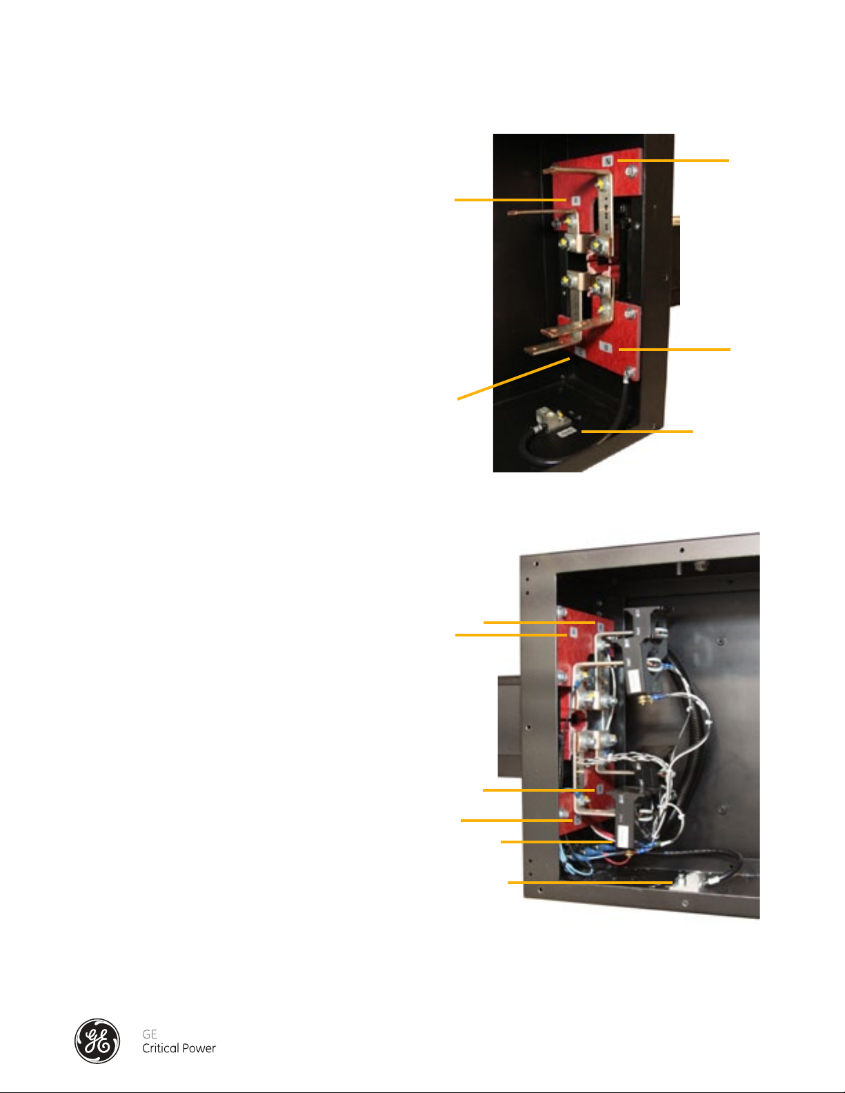
END FEED BOX COMPONENTS
The OPTION 1 configuration (Figure 23) enables power monitoring of the branch circuit loads connected to each BCMSEquipped Tap Off Box. Busway source power input monitoring is not available since the Input Power Monitor board is not
installed in the End Feed.
The Option 1 configured End Feed Box contains the data acquisition system consisting of an Accumulator PCB, and a Power
Inserter PCB (Figure 24). The power disconnects for the circuit boards are the readily accessible fuses mounted on the
outside of the End Feed Box. Ingress to these circuit boards is by removing the cover on the restricted-access Bus Monitor
Housing. This should only be done by a qualified electrical technician as removing the cover will expose high voltage
connections on the circuit boards. If the system logic PCBs have been purchased separately, they must be mounted in an
access-restricted, grounded metal box and a readily accessible appropriate upstream power disconnect must be provided.
For details on the circuit board parameters reference Appendix A: Tap Off Box Monitoring Specifications.
End Feed
Communications Cable
Busrail
Tap Off Box Tap Off Box Tap Off Box Tap Off Box
Figure 23 - Option 1 - Branch Circuits via BCMS-Equipped Tap Off Boxes
Bus Monitor Module (Cover
Removed)
Power Inserter PCB
Accumulator PCB
Bus Monitor Fuse Access
Figure 24 - Option 1 - End Feed Box Monitoring Components
Installation & Operation Manual, GE Series DPB Busway
March 25, 2013, Rev 0
GE Confidential
33
Page 42

Series DPB Busway Installation & Operation Manual
Option 1 - TAP OFF BOX MONITORING ONLY
ACCUMULATOR PCB
J8 USB Port
All communications (power data) from the
Tap Off Boxes are transmitted through the
Accumulator Board (Figure 25). The board
is equipped with a RS-485 serial Modbus
communications serial interface capable of
two-wire or four-wire communications. Refer to
Section "Communications" for details on how to
interface with the serial port for connection to
Building Management Systems (BMS),
Data Center Infrastructure Solutions (DCIM) or
Local Displays.
J6 Modbus
Serial Output
J5 Modbus
Serial Input
Figure 25 - Accumulator PCB
Jumper Pins
POWER INSERTER PCB
DC power for all related circuit boards of the Bus
Monitoring System is supplied through the Power
Inserter Board (Figure 26) located inside the BCMS
Monitoring Module on the End Feed Box. The Power
Inserter Board acquires AC power via a readily accessible
disconnect device directly from the End Feed main AC
input bus. It provides a 24 VDC source along the bus rail
communications cable to power the intelliBUS (Branch
Monitoring) circuit boards in Tap Off Boxes. It is important
that the Power Inserter be configured for the correct
AC input voltage. See Table 1. For the correct jumper
configuration for jumper J2 and J5 located on the Power
Inserter Board.
1234
J2 Voltage
Configuration
J5 Voltage
Configuration
12345
Jumper Pins
Figure 26 - Power Inserter PCB
The input power inserter is always fused with Type KTK-R fuses rated at 0.5A.
480 VAC 380VAC 240VAC 208VAC
J2
J5
2 to 3 2 to 3 1 to 2 and 3 to 4 1 to 2 and 3 to 4
2 to 3 1 to 2 and 3 to 4 2 to 3 1 to 2 and 3 to 4
Table 1 - Power Supply Input Voltage Configuration
Installation & Operation Manual, GE Series DPB Busway
March 25, 2013, Rev 0
GE Confidential
34
Page 43

Series DPB Busway Installation & Operation Manual
Option 1 - TAP OFF BOX MONITORING ONLY
SAFETY WARNING
CAUTION
ALL VOLTAGE CONNECTIONS MUST BE FUSED!
TAP OFF BOX MONITORING COMPONENTS
Each Tap Off Box is BCMS-equipped (Figure 27)
and interconnected with the Accumulator Board
via the Communications Cable Connection
scheme (Figure 23).
Branch Monitor Sensor Board (intelliBUS): This
board monitors 3- phase current (phases A, B,
C) for each branch circuit. Depending on the
configuration of the system, not all current
sensors may be employed.
Fuses
Fusing: The Branch Circuit Monitoring system uses
three fuses (one per phase) to protect the voltage
sensing circuits. Fuses are located on the side of
the Tap Off Box (Figure 27) in screw-type safety
fuses holders. Fuses are Type KTK-R rated at 0.5A.
Note that the state of a fuse on the sensing circuit
will not affect the electrical performance of the
Series DPB Bus System™.
COMMUNICATIONS CABLE CONNECTION
The intelliBUS PCB is located inside the Tap Off
Box. Once the Tap Off Box has been secured to the
bus rail, (refer to section Tap Off Box Installation)
insert the communications cable from the Branch
Monitor Connector on the Tap Off Box into the
nearest open connector on the busrail (Figure 28).
Ensure that the barbed connector lock is in place
to maintain connection integrity.
In the event all communication connectors are
utilized where a Tap Off Box is located, longer
cables or connector splitters are available from
the factory. Once energized, the Status LED will
NOT be lighted as it is used for Alarm purposes
only. Note that the source power for the branch
monitor is via the communications cable link.
IntelliBUS PCB
Figure 27 - Tap Off Box with Branch Circuit Monitoring Installed
Busrail Connector
Tap Off Box
Connector
Communications Cable
Fuses
Status LED
Figure 28 - Tap Off Box Communication Interface Into Series DPB Busrail
Installation & Operation Manual, GE Series DPB Busway
March 25, 2013, Rev 0
GE Confidential
35
Page 44
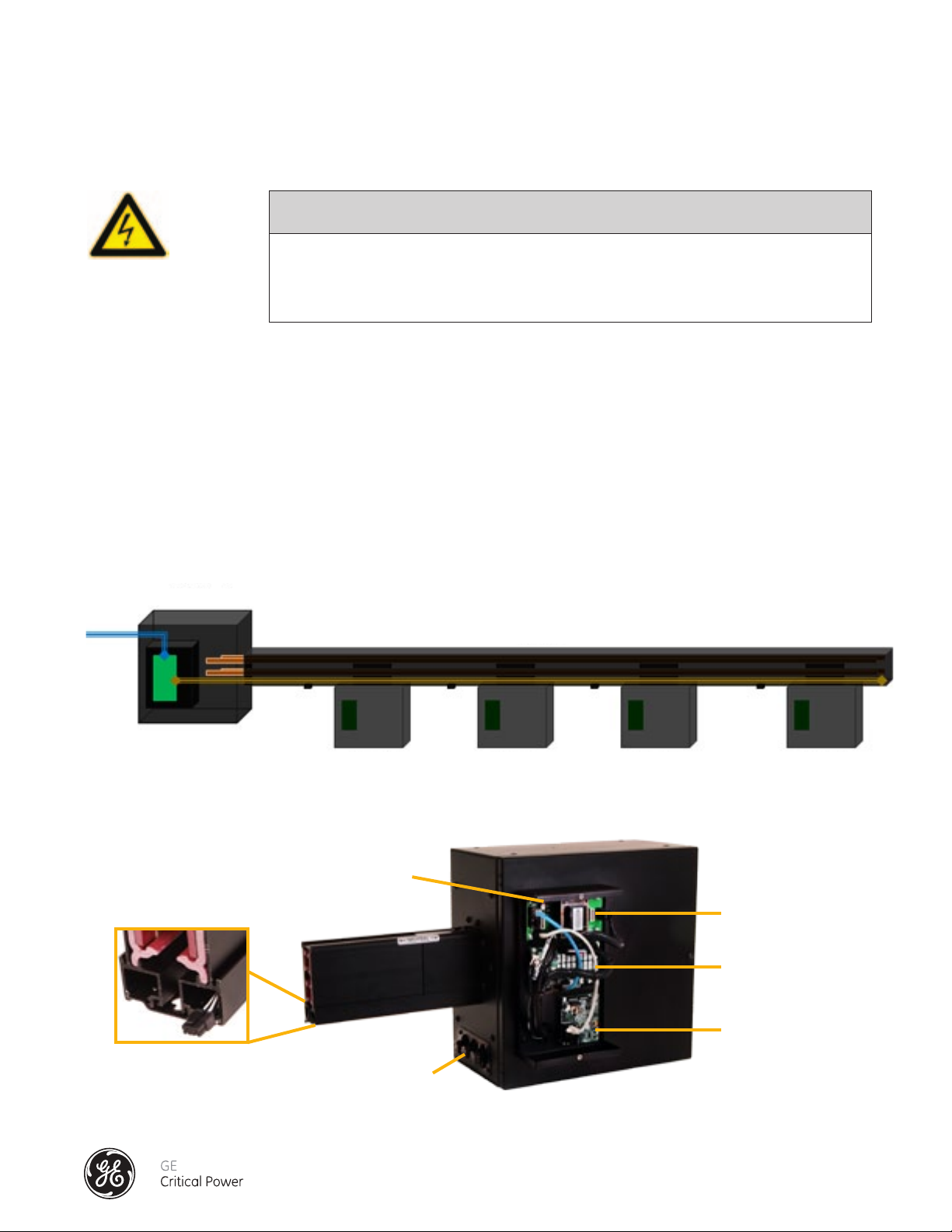
Series DPB Busway Installation & Operation Manual
Option 2 - END FEED MONITORING ONLY
SAFETY WARNING
CAUTION
SEVERE INJURY OR DEATH CAN RESULT FROM ELECTRICAL SHOCK DURING CONTACT WITH
HIGH VOLTAGE CONDUCTORS, MONITORING PCBS, OR RELATED EQUIPMENT. DISCONNECT
AND LOCK OUT ALL POWER SOURCES DURING INSTALLATION AND SERVICE.
END FEED BOX COMPONENTS
The Option 2 configuration (Figure 29) is intended for monitoring of the busway power input only. Only the data acquisition
boards located in the End Feed are utilized for the Busway Input Feeder monitoring.
The End Feed Box contains the main data acquisition system consisting of an Accumulator PCB, a Power Inserter PCB, and
an Input PM PCB (Figure 30). The power disconnects for the circuit boards are the readily accessible fuses mounted on the
outside of the End Feed Box. Ingress to these circuit boards is by removing the cover on the restricted-access Bus Monitor
Housing. This should only be done by a qualified electrical technician as removing the cover will expose high voltage
connections on the circuit boards. If the system logic PCBs have been purchased separately, they must be mounted in an
access-restricted, grounded metal box and a readily accessible appropriate upstream power disconnect must be provided.
For details on the circuit board parameters reference Appendix B: End Feed (Input PM Board) Monitoring Specifications.
End Feed
Communications Cable
Busrail
Tap Off Box Tap Off Box Tap Off Box Tap Off Box
Figure 29 - Option 2 - Busway Input Feeder Monitoring
Bus Monitor Module (Cover
Removed)
Power Inserter PCB
Input PM PCB
Accumulator PCB
Bus Monitor Fuse Access
Figure 30 - Option 2 - End Feed Box Bus Monitoring Components
Installation & Operation Manual, GE Series DPB Busway
March 25, 2013, Rev 0
GE Confidential
36
Page 45
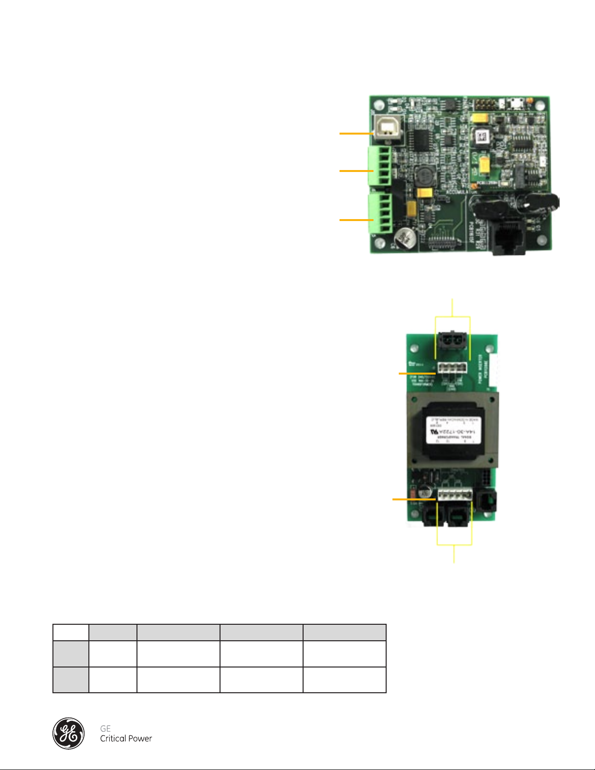
Series DPB Busway Installation & Operation Manual
Option 2 - END FEED MONITORING ONLY
ACCUMULATOR PCB
J8 USB Port
All communications (power data) from the End
Feed Input PM PCB are transmitted through
the Accumulator Board (Figure 31). The board
is equipped with a RS-485 serial Modbus
communications serial interface capable of
two-wire or four-wire communications. Refer to
Section "Communications" for details on how to
interface with the serial port for connection to
Building Management Systems (BMS),
Data Center Infrastructure Solutions (DCIM) or
Local Displays.
POWER INSERTER PCB
DC power for all related circuit boards of the Bus Monitoring
System is supplied through the Power Inserter Board (Figure
32) located inside the Bus Monitor Housing on the End Feed
Box. The Power Inserter Board acquires AC power via a
readily accessible disconnect device directly from the End
Feed main AC input bus. It is important that the Power
Inserter be configured for the correct AC input voltage. See
Table 2. For the correct jumper configuration for jumper J2
and J5 located on the Power Inserter Board.
J6 Modbus
Serial Output
J5 Modbus
Serial Input
Figure 31 - Accumulator PCB
Jumper Pins
1234
J2 Voltage
Configuration
J5 Voltage
Configuration
The input power inserter is always fused with Type KTK-R fuses rated at 0.5A.
480 VAC 380VAC 240VAC 208VAC
J2
J5
2 to 3 2 to 3 1 to 2 and 3 to 4 1 to 2 and 3 to 4
2 to 3 1 to 2 and 3 to 4 2 to 3 1 to 2 and 3 to 4
Table 2 - Power Supply Input Voltage Configuration
Installation & Operation Manual, GE Series DPB Busway
March 25, 2013, Rev 0
12345
Jumper Pins
Figure 32 - Power Inserter PCB
GE Confidential
37
Page 46

Series DPB Busway Installation & Operation Manual
Option 2 - END FEED MONITORING ONLY
INPUT PM PCB
Input Power Monitor (PM) Board: (Figure 33):
this board monitors two separate 3- phase
power sources including voltage, phase
current and neutral, and ground current as
well as four contact alarm inputs.
J2 Voltage
Configuration
J5 Voltage
Configuration
J10 Input
Current 1
(A, B, C)
J13 Input
Current 2
(N, G)
Figure 33 - Input PM Board
J7 External
Contacts
J3 CanBUS
Modbus Power
J11 Input
Current 2
(A, B, C)
J12 Input
Current 2
(N, G)
Installation & Operation Manual, GE Series DPB Busway
March 25, 2013, Rev 0
GE Confidential
38
Page 47

Series DPB Busway Installation & Operation Manual
Option 3 - TAP OFF BOX AND END FEED MONITORING CONCURRENTLY
SAFETY WARNING
CAUTION
SEVERE INJURY OR DEATH CAN RESULT FROM ELECTRICAL SHOCK DURING CONTACT WITH
HIGH VOLTAGE CONDUCTORS, MONITORING PCBS, OR RELATED EQUIPMENT. DISCONNECT
AND LOCK OUT ALL POWER SOURCES DURING INSTALLATION AND SERVICE.
END FEED BOX COMPONENTS
The Option 3 configuration (Figure 34) combines monitoring of the busway power input and power monitoring of the branch
circuit loads connected to each BCMS-Equipped Tap Off Box.
The End Feed Box contains the main data acquisition system consisting of an Accumulator PCB, a Power Inserter PCB, and
an Input PM PCB (Figure 35). The power disconnects for the circuit boards are the readily accessible fuses mounted on the
outside of the End Feed Box. Ingress to these circuit boards is by removing the cover on the restricted-access Bus Monitor
Housing. This should only be done by a qualified electrical technician as removing the cover will expose high voltage
connections on the circuit boards. If the system logic PCBs have been purchased separately, the PCBs must be mounted
in an access-restricted, grounded metal box and a readily accessible appropriate upstream power disconnect must be
provided. For details on the circuit board parameters reference Appendix A: Tap Off Box Monitoring Specifications and
Appendix B: End Feed (Input PM Board) Monitoring Specifications..
End Feed
Figure 34 - Option 3 - End Feed Power and Tap Off Branch Circuits Monitoring
Communications Cable
Busrail
Tap Off Box Tap Off Box Tap Off Box Tap Off Box
Bus Monitor Module (Cover
Removed)
Power Inserter PCB
Input PM PCB
Accumulator Board
Bus Monitor Fuse Access
Figure 35 - Option 3 - End Feed Box Monitoring Components
Installation & Operation Manual, GE Series DPB Busway
March 25, 2013, Rev 0
GE Confidential
39
Page 48

Series DPB Busway Installation & Operation Manual
Option 3 - TAP OFF BOX AND END FEED MONITORING CONCURRENTLY
ACCUMULATOR PCB
All communications (power data) from the
Tap Off Boxes and End Feed Input PM PCB
are transmitted through the Accumulator
Board (Figure 36). The board is equipped with
a RS-485 serial Modbus communications
serial interface capable of two-wire or fourwire communications. Refer to Section
"Communications" for details on how to interface
with the serial port for connection to Building
Management Systems (BMS), Data Center
Infrastructure Solutions (DCIM) or Local Displays.
POWER INSERTER PCB
DC power for all related circuit boards of the Bus Monitoring
System is supplied through the Power Inserter Board (Figure
37) located inside the Bus Monitor Housing on the End Feed
Box. The Power Inserter Board acquires AC power via a readily
accessible disconnect device directly from the End Feed main
AC input bus. It provides a 24 VDC source along the bus rail
communications receptacles to power the intelliBUS (Branch
Monitoring) circuit boards in Tap Off Boxes. It is important
that the Power Inserter be configured for the correct AC input
voltage. See Table 3. For the correct jumper configuration for
jumper J2 and J5 located on the Power Inserter Board.
J8 USB Port
J6 Modbus
Serial Output
J5 Modbus
Serial Input
Figure 36 - Accumulator PCB
Jumper Pins
1234
J2 Voltage
Configuration
J5 Voltage
Configuration
The input power inserter is always fused with Type KTK-R fuses rated at 0.5A.
480 VAC 380VAC 240VAC 208VAC
J2
J5
2 to 3 2 to 3 1 to 2 and 3 to 4 1 to 2 and 3 to 4
2 to 3 1 to 2 and 3 to 4 2 to 3 1 to 2 and 3 to 4
Table 3 - Power Supply Input Voltage Configuration
Installation & Operation Manual, GE Series DPB Busway
March 25, 2013, Rev 0
12345
Jumper Pins
Figure 37 - Power Inserter PCB
GE Confidential
40
Page 49

Series DPB Busway Installation & Operation Manual
Option 3 - TAP OFF BOX AND END FEED MONITORING CONCURRENTLY
INPUT PM PCB
Input Power Monitor (PM) Board: (Figure 38):
this board monitors two separate 3- phase
power sources including voltage, phase
current and neutral, and ground current as
well as four contact alarm inputs.
SAFETY WARNING
CAUTION
J9 Voltage
Configuration
J8 Voltage
Configuration
J10 Input
Current 1
(A, B, C)
J13 Input
Current 2
(N, G)
Figure 38 - Input PM PCB
J7 External
Contacts
J3 CanBUS
Modbus Power
J11 Input
Current 2
(A, B, C)
J12 Input
Current 2
(N, G)
ALL VOLTAGE CONNECTIONS MUST BE FUSED!
TAP OFF BOX MONITORING COMPONENTS
Each Tap Off Box is BCMS-equipped (Figure 39)
and interconnected with the Accumulator Board
via the Communications Cable Connection
scheme (Figure 40).
Branch Monitor Sensor Board (intelliBUS): This
board monitors 3- phase current (phases A, B,
C) for each branch circuit. Depending on the
configuration of the system, not all current
sensors may be employed.
Fusing: The Branch Circuit Monitoring system uses
three fuses (one per phase) to protect the voltage
sensing circuits. Fuses are located on the side of
the Tap Off Box (Figure 34) in screw-type safety
fuses holders. Fuses are Type KTK-R rated at 0.5A.
Note that the state of a fuse on the sensing circuit
will not affect the electrical performance of the
Series DPB Bus System.
Fuses
IntelliBUS PCB
Figure 39 - Tap Off Box with Branch Circuit Monitoring Installed
Installation & Operation Manual, GE Series DPB Busway
March 25, 2013, Rev 0
GE Confidential
41
Page 50

Series DPB Busway Installation & Operation Manual
Option 3 - TAP OFF BOX AND END FEED MONITORING CONCURRENTLY
COMMUNICATIONS CABLE CONNECTION
The intelliBUS PCB is located inside the Tap Off
Box. Once the Tap Off Box has been secured to the
bus rail, (refer to section Tap Off Box Installation)
insert the communications cable from the Branch
Monitor Connector on the Tap Off Box into the
nearest open connector on the busrail (Figure 23).
Ensure that the barbed connector lock is in place
to maintain connection integrity.
Busrail Connector
Fuses
In the event all communication connectors are
utilized where a Tap Off Box is located, longer
cables or connector splitters are available from
the factory. Once energized, the Status LED will
NOT be lighted as it is used for Alarm purposes
only. Note that the source power for the branch
monitor is via the communications cable link.
Figure 40 - Tap Off Box Communication Interface Into Series DPB Busrail
Tap Off Box
Connector
Communications Cable
Status LED
Installation & Operation Manual, GE Series DPB Busway
March 25, 2013, Rev 0
GE Confidential
42
Page 51

Series DPB Busway Installation & Operation Manual
COMMUNICATIONS
The Series DPB Busway BCMS is capable of providing remote communications information in four-wire or two-wire
serial configurations via Modbus™ RTU protocol. It is always suggested to use a shielded twisted pair cable for the
communications interface.
The standard communication setup is through RS422/RS485, four-wire interface with the Tx and Rx on separate pairs due to
the ability to have increased speed on the communications with the Tx and Rx separated. However, it is possible to connect
the Remote Communications to a two-wire network.
The default communications parameters for the interface are 9600 baud, 8 bit, even parity, and 1 stop bit.
There are two different levels of firmware available – BCMS Basic -Current only, and BCMS Plus – Current Plus Voltage.
See Appendix A: TAP OFF BOX MONITORING SPECIFICATIONS, and Appendix B: END FEED (INPUT PM BOARD) MONITORING
SPECIFICATIONS.
Installation & Operation Manual, GE Series DPB Busway
March 25, 2013, Rev 0
GE Confidential
43
Page 52

Series DPB Busway Installation & Operation Manual
CONNECTING THE END FEED BOX TO LOCAL DISPLAYS OR BMS / DCIM SOLUTIONS
Practical operational limits of Modbus are thirty-two devices on a chain which means thirty-two Accumulators can be
connected together. Each device has its own address that limits the number of Accumulators you can have on any Modbus
chain.
There are two communications ports on the Accumulator Board in the End Feed Box for customer communications, J5 and
J6. They are both in parallel, so the End Feeds can be connected in a Modbus daisy chain up to the limits detailed above. The
first port (J6) is dedicated to supplying data to an upstream device acquiring the information. The second port (J5) is used to
link additional acquisition circuit boards to allow a single communications port for multiple boards. Refer to Figure 38 for the
location of the serial port terminal blocks. Be sure to observe polarities and connection points marked on the circuit board
when connecting to the serial port.
The Input Power Monitoring Board in the End Feed and the iBus Board in the Tap Off Boxes have the capability to monitor
multiple sources. The End Feed can monitor two independent three phase sources so designed for a dual bus End Feed.
The iBus Board can monitor 6 currents, two of each phase.
The USB communications port is reserved for factory programming and customization of module parameters. Consult the
External Interface Manual for details.
RS 485 FOUR-WIRE CONNECTION
The four-wire configuration is connected as shown
in Figure 41. When daisy chaining additional
accumulator boards, the output from the first
board (J5) is connected to the input of the second
board (J6). The output going to the serial port of the
external acquisition device, i.e. Modbus™ gateway,
is always connected to J5 of the last board in the
series of boards.
Note(s): Up to 18 boards may be connected on one
string. Jumpers on J9 and J10 must be removed.
If you require a Ground connection, then you
can hook up the Ground connection, but it is not
required.
Customer Building
Management System
Accumulator or
BCMS Hub
Figure 41 - RS485 Four-Wire Connection Scheme
Installation & Operation Manual, GE Series DPB Busway
March 25, 2013, Rev 0
GE Confidential
44
Page 53

Series DPB Busway Installation & Operation Manual
RS 485 TWO-WIRE CONNECTION
The two-wire configuration is connected as shown in
Figure 42. Jumpers placed across J10 and J9 on the
Accumulator PCB.
Customer Building
Management System
Accumulator or
BCMS Hub
Figure 42 - RS485 Two-Wire Connection Scheme
Installation & Operation Manual, GE Series DPB Busway
March 25, 2013, Rev 0
GE Confidential
45
Page 54

Series DPB Busway Installation & Operation Manual
ACCUMULATOR BOARD CONNECTIONS
MODBUS CONNECTION
Upstream connections (connects to customer’s Building Monitoring System). See Figure 43 - End Feed Accumulator Board.
a. Transmit + is J5 OR J6 pin 1
b. Transmit - is J5 OR J6 pin 2
c. Receive + is J5 OR J6 pin 3
d. Receive - is J5 OR J6 pin 4
e. Ground is J5 OR J6 pin 5
J11
J10
J9
J8
J7
5 4 3 2 1 5 4 3 2 1
J6 J5
Figure 43 - End Feed Accumulator Board
Installation & Operation Manual, GE Series DPB Busway
March 25, 2013, Rev 0
GE Confidential
46
Page 55

Series DPB Busway Installation & Operation Manual
BCMS SETUP DOCUMENTATION
REQUIRED MATERIAL
1� USB cable (Male A to Male B)
2� Accumulator_Setup�exe application
3� FTDI Drivers for USB (www�ftdichip�com)
4� Microsoft DotNet (www�microsoft�com/net)
STARTUP
Connect the USB cable to the Accumulator PCB� Wait for it to connect, and then open the Accumulator_Setup�exe file�
You should get a screen that looks similar to Figure 44�
Figure 44 - BCMS Setup Startup Screen
Note: you will not have the same devices listed in the main part of the screen�
If you do not see “USB <-> Accumulator” in the top box, This means you have not connected� Press the “Search” button�
If the name appears press the “Open” button� If not, you need to make sure you have the FTDI drivers installed�
If you get any DLL error, Make sure you have Microsoft DotNet installed�
Installation & Operation Manual, GE Series DPB Busway
March 25, 2013, Rev 0
GE Confidential
47
Page 56

Series DPB Busway Installation & Operation Manual
USING THE ACCUMULATOR SETUP PROGRAM
Main Window (See Figure 45):
Search – Will search for the Accumulator board� When you open the program it will automatically search for an
Accumulator board� If the search is successful “USB <-> Accumulator” should appear in the box beside the search button�
Open – This will open the connection to the Accumulator board� It will automatically open a connection on startup if the
Accumulator board is found�
Close – This will close the connection to the Accumulator board� It will automatically close the connection when the
program is closed�
Version – This is the version of the software in the Accumulator board� This may be helpful if you have issues and need to
contact GE for assistance�
Setup Tab:
The Setup tab is where most of the setup steps will be done� Pressing the “Update” button on the right column will
update the data on this page�
Open
Close
Search
Version
Update
Find Devices
Add
Remove
Swap
Reserve
Insert
Selected On
All Off
Default
Figure 45 - BCMS Setup Tab
At the top is the Modbus setup� You can change the address, parity and baud rate� The addresses are sequential
starting with the base address� To change the address put the desired address in the box and press “Set”� You will see
the addresses of the devices change in the list below� Use the pull-down box beside parity to change it� You can select
even, odd or none� Press “Set” to set the parity� Use the pull- down box beside baud to change it� You can select 9600 or
19200� Press “Set” to set the parity�
Installation & Operation Manual, GE Series DPB Busway
March 25, 2013, Rev 0
GE Confidential
48
Page 57

Series DPB Busway Installation & Operation Manual
In the main part of the window is where the connected devices are shown� In Figure 40 there is one “INP PM” and
two “IBUS” boards� INP PM is short for Input Power Monitor, which is the monitoring for the End Feed Box� IBUS is the
monitoring in the Tap Off boxes� Each device has a Unique Identification Number� This number is shown after the ID tag�
Next is the Modbus address for the device� The Comm: Good/Bad indicates if the Accumulator board is communicating
with the device�
It is important when you setup up the busway to know which box is which� Since all the devices are on a bus, it is
impossible to know one from another� It is recommended that you plug them in one at a time� This will allow you to put
them in the order you desire� Each device has a unique identification number, so once the devices are known, they will
remain in the order you put them in� When a device is found, it will be placed in the next available address shown by “No
Device”, not necessarily at the end of the list�
Figure 46 image shows some more options when setting up the devices:
Figure 46 - BCMS Setup Tab Detail
In Figure 41 we added two more devices� The second device is a reserved spot� The fourth device is a “No Device” or free
device� If another device were added it would be placed in the fourth spot, since the second is reserved� If there were
not free devices, it would be added to the end of the list�
Note: You can have a maximum of 32 devices connected to an Accumulator. This includes free or reserved devices.
The following are a list of the buttons on the right which are used to set up the devices in the list�
Update – This button will get the latest update from the Accumulator� There is a check box under it, when if checked, will
automatically update the data every two seconds�
Find Device – This will go out on the bus and search for new devices� The is done automatically every thirty seconds, but
during setup this will find them faster if needed�
Add – This will Add a reserved device� If you know you will be adding more Tap Off Boxes in the future, or want to leave a
gap for another reason, you can add a reserved spot� No new device will be added in this address� If you want to remove
the reserve, you can use the remove feature�
Remove – To use Remove you must use the check boxes beside the device you wish to remove� This will remove the
device from the list, and put a “No Device” in its place� If you remove the last device on the list it will not add a no device�
It will remove the device all together�
Swap – To use Swap you must use the check two boxes beside the devices you wish to swap� It swaps the locations and
addresses of the two devices�
Reserve – To use Reserve you must use the check box beside the device you wish to reserve� Only a “No Device” spot can
be reserved� This will reserve the spot so new devices will not use this spot� It can be un-reserved by using the remove
on the reserved spot�
Insert – To use Insert you must use the check box beside the device you wish to insert� Insert will insert a “No device”
spot before the selected item� Note: this will change the addresses of every device including and after the checked box�
Installation & Operation Manual, GE Series DPB Busway
March 25, 2013, Rev 0
GE Confidential
49
Page 58

Series DPB Busway Installation & Operation Manual
LED Control – This is used to help find devices on the chain� To use led control you must use the check box beside the
iBus device you wish to find� The “Selected On“ will turn the led on the box on solid for the allotted time in the box below
(in minutes)� The “All Off will turn all the lights back to their current state� Blinking for alarm and off for no alarm�
Default – This will Default the board� Defaulting the board will remove all the setup and convert back to a default state�
You will lose all the Modbus setup, device setup and locations� This is not recommended unless you are moving or
reconfiguring the entire busway�
COMMON PROCEDURES
Removing a Tap Off Box:
If you wish to remove a Tap Off Box you must physically disconnect the Communications Cable from the Tap Off Box and
Busrail Connector� Use “Remove” to remove it from the list� It should now be a “No Device” and the Accumulator will not
look for it anymore� If you do not plan to use this location anymore, you may want to use the “Reserve” and reserve this
spot so any new boxes will be added to the end and not the spot where this box was�
Replacing a Tap Off Box:
If you wish to replace a Tap Off Box and put a new one in its place you must disconnect the old Tap Off Box - see section
Tap Off Box Mounting� Use “Remove” to remove it from the list� Install the new Tap Off Box - see section Tap Off Box
Mounting� As long as it is the first “No Device” in the list is where you want it, it will be added back to the same address�
If not, use the “Swap” command to move it to the previous location�
Adding a Tap Off Box:
If you wish to add a Tap Off Box in the first “No Device” spot or at the end, install the new Tap Off Box - see section Tap
Off Box Mounting� Connect the Communications Cable to the Tap Off Box and and an available Busrail Communications
Connector� If you wish to add it to a reserved spot, you will need to remove the reserved by using the “Remove”
command before installation�
Installation & Operation Manual, GE Series DPB Busway
March 25, 2013, Rev 0
GE Confidential
50
Page 59

Series DPB Busway Installation & Operation Manual
DATA TA B
The Data tab can be used to see the data for any connected device� It can also be used to setup the parameters for any
specific device�
Figure 47 - BCMS Setup Data Tab Window
The Pull-Down box at the top-left of the page can be used to change the device you wish to see� The Update box will get
the current data from the device� Any time you change devices it will automatically update the data�
All of the points in the Points List are shown on the main window� You can scroll down to see all of them� The selected
point can be seen on the right side in the “Write to Modbus” area�
In the “Write to Modbus” area you will see the data for the selected point on the left� If you can change the data, the set
button will be active� If it is an alarm register the set button will be replaced by a clear button�
In the “Unit Name” area is the name� This is derived from the last 8 points in the points list� You can change the name of
the device, up to 16 characters, to make it easier to identify� The ‘Set” button will change the registers for the name�
Under the “Unit Name” area is a box which will decode several of the alarm and setup registers� It will not show up until
you have selected one of these registers� Alarm registers will show you a list of the current alarms� Setup boxes will
show a list of setup options which you can check or uncheck� Changing the setup will change the data in the box at the
top of the page� This will not be set unless you press the “Set” button in the “Write to Modbus” area�
At the Bottom of the page are the “Save Memory”, “Load Memory”, and “Load Default” buttons� Making changes to the
setup will make these changes on the board, but will not save them in the on board EEPROM� The “Save Memory” will save
any changes you have made to the on board EEPROM� “Load Memory” will read the values from EEPROM into the board in
case you make unwanted changes� “Load Default” will load default values, which should only be done on initial program�
Installation & Operation Manual, GE Series DPB Busway
March 25, 2013, Rev 0
GE Confidential
51
Page 60

Series DPB Busway Installation & Operation Manual
On the right of the page are several buttons which will take you to alarm and setup parameters� All they do is change
the location of the points on the left of the page�
WINDOW TAB
This window is just a direct link into the USB commands� This window does not need to be used by the customer� All the
commands on this page can be done on the previous pages with buttons to make it easier to do�
Installation & Operation Manual, GE Series DPB Busway
March 25, 2013, Rev 0
GE Confidential
52
Page 61

Series DPB Busway Installation & Operation Manual
CUSTOMER CONNECTIONS TO 7" LOCAL DISPLAY
PRODUCT INTRODUCTION
Figure 48 - 7" Series DPB Bus Systems Local Display
The 7” Local Monitor Display is a high-performance, 800 x 480 pixel LED backlit color LCD display with a resistive touch
screen interface.
It is used with the Series DPB Busway to provide a graphic display of the detailed power parameter data for the busway
power source input (End Feed Boxes) and the branch circuits of the power distribution units (Tap Off Boxes).
The local monitor can be configured to display the power parameters of up to six End Feeds each with up to fifteen Tap Off
Boxes – a total of 96 device addresses.
POWER PARAMETERS MONITORED
End Feeds: (See Figure 49)
Voltage - (L-L, L-N, THD%, Freq.)
Current – (3 phases, N, G, Max., Demand, Crest Factor)
Power – (kW, kVA, kVAR, PF, kWH[A], kWH[B], kWH[C])
Percent Load – ( 3 phases)
Tap Off Boxes: (See Figure 50)
Voltage - (L-L, L-N, THD%, Freq.)
Current – (3 phases, N, G, Max., Demand, Crest Factor, for all poles)
Power – (kW, kVA, kVAR, PF, kWH[A], kWH[B], kWH[C] for all poles)
Percent Load – ( 3 phases for all poles)
Installation & Operation Manual, GE Series DPB Busway
March 25, 2013, Rev 0
GE Confidential
53
Page 62

Series DPB Busway Installation & Operation Manual
Figure 49 - 7" Local Display End Feed Screenshot
Figure 50 - 7" Local Display Tap Off Box Screenshot
Installation & Operation Manual, GE Series DPB Busway
March 25, 2013, Rev 0
GE Confidential
54
Page 63

Series DPB Busway Installation & Operation Manual
COMPONENT IDENTIFICATION
See Figure 51 - 7" Series DPB Local Display Primary Components
The 7" Series DPB Local Display has the following primary components:
1.) Wall Mountable Housing
2.) 7" Touchscreen Display
3.) Power Supply Board
4.) IX Display Inferface Board
1.) Wall Mountable Housing
4.) IX Display Interface Board
Figure 51 - 7" Series DPB Local Display Primary Components
3.) Power Supply Board
2.) 7" IX Display Connections
Installation & Operation Manual, GE Series DPB Busway
March 25, 2013, Rev 0
GE Confidential
55
Page 64

Series DPB Busway Installation & Operation Manual
POWER CONNECTIONS
See Figure 52 - IX Display Interface Board for connection points.
120Vac
1.) Phase Voltage connects to TB1 pin 3
2.) Neutral Voltage connects to TB1 pin 1
3.) Ground connects to TB2 pin 3
24Vdc
1.) +24V connects to TB2 pin 1
2.) 24V return connects to TB2 Pin 2
3.) Ground connects to TB2 pin 3
1 2 3 1 2 3
TB1 TB2
Figure 52 - IX Display Interface Board
Installation & Operation Manual, GE Series DPB Busway
March 25, 2013, Rev 0
GE Confidential
56
Page 65

Series DPB Busway Installation & Operation Manual
MODBUS CONNECTION
Connecting the Local Display to the busway is achieved by daisy-chaning up to 6 End Feed Accumulator PCBs via
Connection TB3 (see Figures 53). A total of 15 Tap Off Boxes per End Feed can be addressed on the display providing a
maximum of 96 power points that can be monitored. Connecting the Series DPB Local Display to a building management
system utilizes Connector TB4.
End Feed Accumulator PCB
Series DPB Bus Systems
TB3
Building
Management
System
TB4
Series DPB Bus Systems
7" Local Display
Figure 53 - Modbus Wiring Diagram
Installation & Operation Manual, GE Series DPB Busway
March 25, 2013, Rev 0
GE Confidential
57
Page 66

Series DPB Busway Installation & Operation Manual
MODBUS CONNECTIONS ON IX DISPLAY INTERFACE BOARD
See Figure 54 for MODBUS Connections on IX Display Interface Board
Downstream Connection utilize Connector TB3 - Connects to End Feed Daisy Chain
1.) Transmit + is TB3 pin 1
2.) Transmit - is TB3 pin 2
3.) Receive + is TB3 pin 3
4.) Receive - is TB3 pin 4
5.) Ground is TB3 pin 5
Upstream Connections utilize Connector TB4 - Connects to customer's building management system.
1.) Transmit + is TB4 pin 1
2.) Transmit - is TB4 pin 2
3.) Receive + is TB4 pin 3
4.) Receive - is TB4 pin 4
5.) Ground is TB4 pin 5
1 2 3 4 5 1 2 3 4 5
TB3 TB4
Figure 54 - Connections on IX Display Interface Board
Installation & Operation Manual, GE Series DPB Busway
March 25, 2013, Rev 0
GE Confidential
58
Page 67

Series DPB Busway Installation & Operation Manual
MODBUS TO 7" LOCAL DISPLAY WIRING SCHEMATIC
COM3/COM4
Connection
24 VDC
OUTPUT
ETHERNET
Connection
INPUT
85-264VAC
COM1/COM2
Connection
7" Display
24 VDC
Connection
INTERFACE
BOARD
OPTIONAL
POWER SUPPLY
85-264VAC
INPUT
TO RESET
24VDC INPUT RS422/485 RS422/485
SWITCH
Figure 55 - Modbus to 7" Local Display Wiring Schematic
Installation & Operation Manual, GE Series DPB Busway
March 25, 2013, Rev 0
GE Confidential
59
Page 68

Series DPB Busway Installation & Operation Manual
CHANGE MODBUS RTU FROM RS422 TO VIA ETHERNET
1.) On the SETUP screen press the “Modbus Setup” button.
2.) Enter User ID and Password, and press the “Modbus Setup” button again.
3.) From the CHANGE ACTIVE CONTROLLER screen, Select “ModbusMaster”
so it is highlighted, and press “Settings” buton.
4.) The settings should look like the following:
Modbus Mode Via Rs422 Via etheRnet
Settings
- Communication Mode Serial Serial
- Default Station 1 1
- Modbus Protocol RTU RTU
- 32bit Work Mapping Motorola Motorola
- Addressing Decimal Decimal
- Start Address 1-based 1-based
- Max Block Size (words) 16 16
- Force Function Code 0x10 Disabled Disabled
- String Swap Disabled Disabled
- Silent Time (ms) 1 1
- Clock Register 0 0
- Serial
- Port Com2 Com2
- Baud 9600 9600
- Parity Even Even
- Data bits 8 8
- Stop bits 1 1
Advanced
- Enable Unicode False False
- Byte Order Intel Intel
- Timeout 400 400
- Retries 3 3
- Offline station retry time 10 10
- Hide Comm. Error False False
- Command Line Option
Installation & Operation Manual, GE Series DPB Busway
March 25, 2013, Rev 0
GE Confidential
60
Page 69

Series DPB Busway Installation & Operation Manual
Modbus Mode Via Rs422 Via etheRnet
Routing
- Communication
- Mode Transparent Transparent
- Timeout 5s 5s
- Serial Port Com4 Com4
- Baud 9600 9600
- Parity Even Even
- Data bits 8 8
- Stop bits 1 1
- Ethernet Port 502 502
5.) To change from RS422 to Ethernet, change the “Communication” box under Routing
from “Serial” to “TCP” or vice versa.
6.) Press “OK” on the PROPERTIES box. You may need to drag the box up to see the “OK” button.
7.) Press “OK” on the CHANGE ACTIVE CONTROLLER box.
8.) Press “OK” on the PROJECT MUST RESTART box.
9.) Press the “Reset” button. The reset button is recessed in a small hold on the left side
of the bottom of the enclosure
10.) Wait for the unit to reboot.
Serial TCP
Installation & Operation Manual, GE Series DPB Busway
March 25, 2013, Rev 0
GE Confidential
61
Page 70

Series DPB Busway Installation & Operation Manual
APPENDIX A: TAP OFF BOX MONITORING SPECIFICATIONS
BCMS Basic = Current Only
BCMS Plus = Current + Voltage
MONITORED PARAMETERS
PARAMETER DESCRIPTION RESOLUTION NOTES
Current (A):
Maximum Current (A):
Minimum Current (A):
Percent Load (% Max):
A, B, C (circuit breaker 1);
A, B, C (circuit breaker 2)
A, B, C (circuit breaker 1);
A, B, C (circuit breaker 2)
A, B, C (circuit breaker 1);
A, B, C (circuit breaker 2)
A, B, C (circuit breaker 1);
A, B, C (circuit breaker 2)
0.1 A Input source current
1
0.1 A Maximum input current detected
1
0.1 A Minimum input current detected
1
0.1%
1
Requires personalization of circuit
breaker current rating
Voltage (VAC): A, B, C Phase (L-L, L-N) 0.1 VAC Input source voltage
Crest Factor
(Peak A RMS):
Real Power (kW):
Apparent Power (kVA):
Reactive Power: (kVAR):
Power Factor (PF):
Energy Usage (kWh):
Total Harmonic
Distortion (%THD):
Frequency (Hz): A phase (40 – 70 Hz) 0.1 Hz
Circuit Temperature
Range (°C):
Bus Junction
Temperature Range
(°C):
1
Neutral and Ground currents may be monitored in addition to phase currents; see note on neutral and ground current monitoring
A, B, C (circuit breaker 1);
A, B, C (circuit breaker 2)
A, B, C (circuit breaker 1);
A, B, C (circuit breaker 2)
A, B, C (circuit breaker 1);
A, B, C (circuit breaker 2)
A, B, C (circuit breaker 1);
A, B, C (circuit breaker 2)
A, B, C (circuit breaker 1);
A, B, C (circuit breaker 2)
A, B, C (circuit breaker 1);
A, B, C (circuit breaker 2)
0.001 A
1
0.01 kW kW (real power) per circuit breaker
1
0.01 kVA
1
0.01 kVAR
1
0.01 PF
1
1 kW
1
A, B, C Phase 0.1%
Circuit Board Temperature
(Min. / Max.)
Temperature Sensors Min. /
Max. (1, 2, 3, 4)
1°C Utilizes on board sensor
1°C
Peak waveform current divided by
RMS current of the waveform
kVA (apparent power) per circuit
breaker
kVAR (reactive power) per circuit
breaker
Load Power Factor per circuit
breaker
Energy consumption per circuit
breaker
Total Harmonic Distortion (load) per
phase measured to 3rd, 5th, 7th, 9th,
11th, 13th harmonics.
Source frequency as measured from
phase A.
Utilizes remote sensors located on
bus junction; may not be present in
all cases.
BCMS
BASIC
a a
a a
a a
a a
BCMS
PLUS
a
a
a
a
a
a
a
a
a
a
a
Installation & Operation Manual, GE Series DPB Busway
March 25, 2013, Rev 0
GE Confidential
62
Page 71

Series DPB Busway Installation & Operation Manual
BCMS Basic = Current Only
BCMS Plus = Current + Voltage
ALARM PARAMETERS
ALARM DESCRIPTION NOTES
Current Loss /
Zero Current:
Current Warning Alarm:
Current High Alarm:
Global Alarms:
A,B,C (circuit breaker 1),
A,B,C (circuit breaker 2)
A,B,C (circuit breaker 1),
A,B,C (circuit breaker 2)
A,B,C (circuit breaker 1),
A,B,C (circuit breaker 2)
Current Warning Alarm Indicates if any current warning alarm is active
High Current Alarm Indicates if any high current alarm is active
Zero Current Alarm
Overvoltage Alarm Indicates if any over voltage alarm is active
Activated when current goes above 1.5 A then to zero
Amps; can signify tripped or open circuit breaker or loss of
input current
User defined based on a percentage of circuit breaker
rating; default is 70%
Alarms when current exceeds threshold after time delay
(default is zero seconds )
User defined based on a percentage of circuit breaker
rating(default is 85%); alarms when current exceeds
threshold after time delay; default is 10 seconds
Typically used to indicate when circuit approached trip
threshold
Indicates if any zero current alarm is active (indicates
breaker trip or breaker open or loss of source)
BCMS
BASIC
a a
a a
a a
a a
a a
a a
BCMS
PLUS
a
Undervoltage Alarm Indicates if any under voltage alarm is active
Over Temperature Alarm Indicates if any over temperature alarm is active
Under Temperature Alarm Indicates if any under temperature alarm is active
Overvoltage Alarm: (L-N Voltage) User defined; default is 200 VAC; no time delay
Undervoltage Alarm: (L-N Voltage) User defined; default is 120 VAC
a
a
a
a
a
Installation & Operation Manual, GE Series DPB Busway
March 25, 2013, Rev 0
GE Confidential
63
Page 72

Series DPB Busway Installation & Operation Manual
BCMS Basic = Current Only
BCMS Plus = Current + Voltage
PERSONALIZATION
PARAMETER DESCRIPTION RESOLUTION NOTES
Circuit Breaker Size: Output circuit breaker rating 1 A.
Warning Time Delay:
Alarm Time Delay:
Demand Average Time:
Current Warning Alarm:
Current High Alarm:
Voltage Range: Source voltage 0.1 V
Frequency: Source frequency 0.1 Hz Defines frequency (60 Hz or 50 Hz)
Board Name Personalization:
Overvoltage Alarm:
Undervoltage Alarm:
Time (seconds) before warning alarm activates
Time (seconds) before alarm
activates
Time (seconds) to
determine average current
Circuit breaker current first
level alarm
Circuit breaker current
second level alarm
User defined device name Alphanumeric
High voltage detected on
source
Low voltage detected on
source
0-60 seconds
0-60 seconds
1 second
40-100%
50-100%
0.1V
0.1V
Defines output circuit breaker ratings;
default is 20 A ; (20-100 A range)
Defines duration current must
exceed threshold before activating
a current warning alarm; default is 0
seconds
Defines duration current must
exceed threshold before activating
a high current alarm; default is 10
seconds
Defines time by which average
current is determined; default is 15
seconds. Range is 15 - 60 seconds
Defines threshold based on a
percentage of circuit breaker rating
(default is 70%) to activate current
warning alarm after a time delay
(default is zero seconds)
Defines threshold based on a
percentage of circuit breaker rating
(default is 85%) to activate high current alarm after a time delay (default
is 10 seconds)
Defines monitored voltage (208, 480,
600 VAC)
Device name; 16 Character maximum
Defines voltage to activate over voltage alarm .(default is 200 VAC)
Defines voltage to activate under
voltage alarm (default is 60 VAC)
BCMS
BASIC
a a
a a
a a
a a
a a
a a
BCMS
PLUS
a
a
a
a
a
Installation & Operation Manual, GE Series DPB Busway
March 25, 2013, Rev 0
GE Confidential
64
Page 73

Series DPB Busway Installation & Operation Manual
APPENDIX B: END FEED (INPUT PM PCB) MONITORING
SPECIFICATIONS
BCMS Basic = Current Only
BCMS Plus = Current + Voltage
MONITORED PARAMETERS
PARAMETER DESCRIPTION
Current (A):
Maximum Current (A):
Minimum Current (A):
Current (A):
Percent Load Utilization (%):
Voltage Source 1 and
2 (VAC):
Crest Factor
(Peak A RMS):
Real Power (kW):
Apparent Power (kVA):
Reactive Power (kVAR):
Power Factor (PF):
Energy Usage (kWh):
Total Harmonic
Distortion (%THD):
Frequency (Hz): A phase (40 – 70 Hz) 0.1 Hz
1
Neutral and Ground currents may be monitored in addition to phase currents; see note on neutral and ground current monitoring.
A, B, C (circuit breaker 1);
A, B, C (circuit breaker 2)
A, B, C (circuit breaker 1);
A, B, C (circuit breaker 2)
A, B, C (circuit breaker 1);
A, B, C (circuit breaker 2)
A, B, C (circuit breaker 1);
A, B, C (circuit breaker 2)
A, B, C (circuit breaker 1);
A, B, C (circuit breaker 2)
A, B, C Phase (L-L, L-N) –
source 1;
A, B, C Phase (L-L, L-N) –
source 2
A, B, C (circuit breaker 1);
A, B, C (circuit breaker 2)
A, B, C (circuit breaker 1);
A, B, C (circuit breaker 2)
A, B, C (circuit breaker 1);
A, B, C (circuit breaker 2)
A, B, C (circuit breaker 1);
A, B, C (circuit breaker 2)
A, B, C (circuit breaker 1);
A, B, C (circuit breaker 2)
A, B, C (circuit breaker 1);
A, B, C (circuit breaker 2)
A, B, C Phase (source1);
A, B, C Phase (source2);
RESO-
LUTION
0.1 A
1
0.1 A Maximum input current detected per phase
1
0.1 A Minimum input current detected per phase
1
0.1 A
1
0.1%
0.1 VAC Input source voltage(s)
0.001 A
0.01 kW kW (real power) per phase
0.01 kVA kVA (apparent power) per phase
0.01
kVAR
0.01 PF Load Power Factor per phase
0.01 kW Energy consumption per phase
0.1%
Input source current(s); neutral and ground
current optional
Average input current monitored over 15-60
minutes rolling average (user defined)
Percentage of maximum circuit breaker
current utilization. Requires personalization
of circuit breaker current rating
Peak waveform current divided by average
RMS current of the waveform; per phase
kVAR (reactive power) per phase
Total Harmonic Distortion (load) per phase
measured to 3rd, 5th, 7th, 9th, 11th, 13th
harmonics
Source frequency as measured from phase
A
NOTES
BCMS
BASIC
a a
a a
a a
a a
a a
BCMS
PLUS
a
a
a
a
a
a
a
a
a
Installation & Operation Manual, GE Series DPB Busway
March 25, 2013, Rev 0
GE Confidential
65
Page 74

Series DPB Busway Installation & Operation Manual
BCMS Basic = Current Only
BCMS Plus = Current + Voltage
ALARM PARAMETERS
PARAMETER DESCRIPTION NOTES
Indicates current exceeds user defined threshold (expressed as a percentage of circuit breaker rating).
Default rating is 70% of breaker capacity.
Alarm activates after a user defined time limit (default is
0 seconds)
Indicates current exceeds user defined threshold (expressed as a percentage of circuit breaker rating).
Default rating is 85% of breaker capacity.
Alarm activates after a user defined time limit (default is
10 seconds)
Current Warning Alarm:
Current High Alarm:
Global Alarms:
A, B, C (circuit breaker 1),
A, B, C (circuit breaker 2)
A, B, C (circuit breaker 1),
A, B, C (circuit breaker 2)
Current Warning Alarm Indicates if any current warning alarm is active.
High Current Alarm Indicates if any high current alarm is active
Overvoltage Alarm Indicates if any over voltage alarm is active
BCMS
BASIC
a a
a a
a a
a a
BCMS
PLUS
a
Undervoltage Alarm Indicates if any under voltage alarm is active
Overvoltage Alarm: (L-N Voltage) Indicates voltage exceeds user defined threshold
Undervoltage Alarm: (L-N Voltage) Indicates voltage is below user defined threshold
Digital Input Alarm: Digital inputs 1, 2, 3, 4
Indicates closed status of dry contact digital inputs (for
customer use)
a
a
a
a
Installation & Operation Manual, GE Series DPB Busway
March 25, 2013, Rev 0
GE Confidential
66
Page 75

Series DPB Busway Installation & Operation Manual
BCMS Basic = Current Only
BCMS Plus = Current + Voltage
PERSONALIZATION
PARAMETER DESCRIPTION RESOLUTION NOTES
Defines source circuit breaker
Circuit Breaker Size: Source circuit breaker rating 1 A
Warning Time Delay:
Alarm Time Delay:
Demand Average Time:
Current Warning Alarm:
Current High Alarm:
Frequency: Source frequency 0.1 Hz Defines frequency (60 Hz or 50 Hz)
Board Name Personalization
Overvoltage Alarm:
Undervoltage Alarm:
Time (seconds) before warning alarm activates
Time (seconds) before alarm
activates
Time (seconds) to determine
average current
Circuit breaker current first
level alarm threshold
Circuit breaker current second level alarm threshold
User defined device name 16 Char
High voltage detected on
source
Low voltage detected on
source
0-60 seconds
0-60 seconds
1 second
40-100%
50-100%
0.1V
0.1V
rating; default is 250 A (1 A increments); 50-600 A range
Defines duration current must
exceed threshold before activating a current default is 0 seconds
warning alarm;
Defines duration current must
exceed threshold before activating
a high current alarm; default is 10
seconds
Defines time by which average
current is determined; default is 15
seconds; range is 15-60 seconds
Defines threshold based on a
percentage of circuit breaker rating
(default is 70%) to activate current
warning alarm after a time delay
(default is zero seconds).
Defines threshold based on a
percentage of circuit breaker rating
(default is 85%) to activate high
current alarm after a time delay
(default is 10 seconds).
Device name; 16 Character maximum
Defines voltage to activate over
voltage alarm
Defines voltage to activate under
voltage alarm
BCMS
BASIC
a a
a a
a a
a
a a
a a
BCMS
PLUS
a
a
a
a
a
Installation & Operation Manual, GE Series DPB Busway
March 25, 2013, Rev 0
GE Confidential
67
Page 76

Series DPB Busway Installation & Operation Manual
APPENDIX C: BUS MONITORING SYSTEM SCHEMATIC DIAGRAMS
BRANCH CIRCUIT MONITORING SYSTEM BOARD INTERCONNECTION
Figure 56 - Branch Circuit Monitoring System Board Interconnection
Installation & Operation Manual, GE Series DPB Busway
March 25, 2013, Rev 0
GE Confidential
68
Page 77

Series DPB Busway Installation & Operation Manual
INPUT POWER MONITOR BOARD TO END FEED CURRENT TRANSFORMERS CONNECTIONS
See Figure 57 - Input Power Monitor Board to End Feed Current Transformers Schematic
See Figure 58 - End Feed Input Power Monitor Board for Connector Locations.
J10 Connector
J12 Connector
J13 Connector
J11 Connector
Figure 57 - Input Power Monitor Board to End Feed Current Transformers Schematic
Installation & Operation Manual, GE Series DPB Busway
March 25, 2013, Rev 0
GE Confidential
69
Page 78

Series DPB Busway Installation & Operation Manual
J10
J12
J13
Figure 58 - End Feed Input Power Monitor Board
J11
The Black wire goes to X1 on CT. The White wire to other CT terminal (X2).
H1 marking on CT faces customer power source (See Figure 59 Below).
Figure 59 - End Feed Current Transformer (CT) Orientation
Installation & Operation Manual, GE Series DPB Busway
March 25, 2013, Rev 0
GE Confidential
70
Page 79

Series DPB Busway Installation & Operation Manual
APPENDIX D: POINTS LIST FOR THE END FEED INPUT PM PCB
All Modbus variables are stored in 16-bit integer format.
# R/W NV Description
These registers show the Main voltages and are in tents of a volt (1215 = 121.5 Amps)
1. R/W Main Voltage1, phase AB
2. R/W Main Voltage1, phase BC
3. R/W Main Voltage1, phase CA
4. R/W Main Voltage1, phase AN
5. R/W Main Voltage1, phase BN
6. R/W Main Voltage1, phase CN
7. R/W Main Voltage2, phase AB
8. R/W Main Voltage2, phase BC
9. R/W Main Voltage2, phase CA
10. R/W Main Voltage2, phase AN
11. R/W Main Voltage2, phase BN
12. R/W Main Voltage2, phase CN
An Over Voltage Alarm occurs if the Any L-N voltage is greater than this threshold register at any time and is
given in tenths of a volt (1200 = 120.0 Volts). For Defaults see the Voltage Type register.
13. R/W NV Over Voltage Alarm Threshold Main
An Under Voltage Alarm occurs if the Any L-N voltage is less than this threshold register at any time and is given
in tenths of a volt (1200 = 120.0 Volts) For Defaults see the Voltage Type register.
14. R/W NV Under Voltage Alarm Threshold Main
Frequency is measured from the phase A voltage input. Range is 40.0-70.0Hz: This register will read as 0xFFFF if
frequencies outside of this range or if sufficient voltage is not present on phase A for an accurate determination.
15. R Frequency
These registers show Total Harmonic Distortion (THD) calculations and are given in tenth of a percent (01 = 0.1%).
16. R Main Voltage1, phase A THD
17. R Main Voltage1, phase B THD
18. R Main Voltage1, phase C THD
19. R Main Voltage2, phase A THD
20. R Main Voltage2, phase B THD
21. R Main Voltage2, phase C THD
Installation & Operation Manual, GE Series DPB Busway
March 25, 2013, Rev 0
GE Confidential
71
Page 80

Series DPB Busway Installation & Operation Manual
This register shows what Voltage values that are being read by this board�
Note Maximum Minimum Default Limits for each Voltage Type are:
208 Phase to Phase High 239 Low 177
Neutral High 138 Low 102
380 Phase to Phase High 437 Low 323
Phase to Neutral High 252 Low 186
400 Phase to Phase High 460 Low 340
Phase to Neutral High 265 Low 196
415 Phase to Phase High 518 Low 383
Neutral High 299 Low 221
480 Phase to Phase High 552 Low 408
Phase to Neutral High 319 Low 236
600 Phase to Phase High 690 Low 510
Phase to Neutral High 398 Low 295
If your voltage is between the limits, pick the Higher Limit�
22� R/W NV Voltage Type (208, 380, 400, 415, 480, 600)
This register shows the setting for the Voltage monitoring setup� A set bit indicated active value�
23� R/W NV Voltage Option Setting
bit 0: Voltage option side 1 set
bit 1: Voltage option side 2 set
bit 2: Set for 50 Hz
bit 3: Auto Adjust Gain�
bits 4 – 15: Not Used Always read as 0
These registers show the phase currents and are given in tenth of amps (100 = 10�0 Amps)
Note: For Neutral and Ground options see Current Options and read the note with these options�
24� R/W Current, Phase 1A
25� R/W Current, Phase 1B
26� R/W Current, Phase 1C
27� R/W Current, Side 1 Neutral (option)
28� R/W Current, Side 1 Ground (option)
29� R/W Current, Phase 2A
30� R/W Current, Phase 2B
31� R/W Current, Phase 2C
32� R/W Current, Side 2 Neutral (option)
33� R/W Current, Side 2 Ground (option)
34� R Current, Phases 1A & 2A
35� R Current, Phases 1B & 2B
36� R Current, Phases 1C & 2C
These registers show the minimum phase currents and are in tenth of amps (100 = 10�0 Amps)
37� R Minimum Current, Phase 1A
38� R Minimum Current, Phase 1B
39� R Minimum Current, Phase 1C
40� R Minimum Current, Phase 1N
41� R Minimum Current, Phase 1G
42� R Minimum Current, Phase 2A
43� R Minimum Current, Phase 2B
Installation & Operation Manual, GE Series DPB Busway
March 25, 2013, Rev 0
GE Confidential
72
Page 81

Series DPB Busway Installation & Operation Manual
44� R Minimum Current, Phase 2C
45� R Minimum Current, Phase 2N
46� R Minimum Current, Phase 2G
47� R Minimum Current, Phases1A & 2A
48� R Minimum Current, Phases 1B & 2B
49� R Minimum Current, Phases 1C & 2C
These registers show the maximum phase currents and are in tenth of amps (100 = 10�0 Amps)
50� R Maximum Current, Phase 1A
51� R Maximum Current, Phase 1B
52� R Maximum Current, Phase 1C
53� R Maximum Current, Phase 1N
54� R Maximum Current, Phase 1G
55� R Maximum Current, Phase 2A
56� R Maximum Current, Phase 2B
57� R Maximum Current, Phase 2C
58� R Maximum Current, Phase 2N
59� R Maximum Current, Phase 2G
60� R Maximum Current, Phases 1A & 2A
61� R Maximum Current, Phases 1B & 2B
62� R Maximum Current, Phases 1C & 2C
Writing this register will reset the current Min and Max registers to the current value�
63� W Min/Max Reset
These registers set the capacity of full load allowed for the alarms� Units are in Amps (125 = 125 Amps)� The
Values that are written must be between 100 and 650� The Default is 250 Amps
64� R/W NV Full Load Side One
65� R/W NV Full Load Side Two
These registers show current demand per phase and are in tenth of amps (262 = 26�2 Amps)� Values are the
average current over the time given in the Demand Register�
66� R Demand phase 1A
67� R Demand phase 1B
68� R Demand phase 1C
69� R Demand phase 2A
70� R Demand phase 2B
71� R Demand phase 2C
The Demand Register is time that the demand is averaged over in minutes� It must be between 10 to 60
minutes� The Default is 15 minutes�
72� R/W NV Demand time
These registers show Percent load and is given in tenth of a percent (753 = 75�3%)� These percents are the
Amps per phase divided by the full load of that side�
73� R Percent load phase 1A
74� R Percent load phase 1B
75� R Percent load phase 1C
76� R Percent load phase 2A
77� R Percent load phase 2B
Installation & Operation Manual, GE Series DPB Busway
March 25, 2013, Rev 0
GE Confidential
73
Page 82

Series DPB Busway Installation & Operation Manual
78� R Percent load phase 2C
These registers show crest factor per phase� Values are peak current/rms current with three decimal places
(1412 = 1�412)�
79� R Crest Factor phase 1A
80� R Crest Factor phase 1B
81� R Crest Factor phase 1C
82� R Crest Factor phase 2A
83� R Crest Factor phase 2B
84� R Crest Factor phase 2C
The following Warning Register sets a bit for every channel, which reads a current above the Warning
Threshold for at least the Warning Time-Delay� All warnings are latching and must be reset by the controller�
To reset any alarm, read the register and the write the register with the desired alarm bit cleared�
85� R/W NV Warning Register (Latching)
bit 0: Phase 1A
bit 1: Phase 1B
bit 2: Phase 1C
bit 3: Phase 2A
bit 4: Phase 2B
bit 5: Phase 2C
bits 6 – 15: Not Used Always read as 0
The following Alarm Register sets a bit for every channel, which reads a current above the Alarm Threshold for
at least the Alarm Time-Delay� All alarms are latching and must be reset by the controller� To reset any alarm,
read the register and then write the register with the desired alarm bit cleared�
86� R/W NV Alarm Register (Latching)
bit 0: Phase 1A
bit 1: Phase 1B
bit 2: Phase 1C
bit 3: Phase 2A
bit 4: Phase 2B
bit 5: Phase 2C
bits 6 – 15: Not Used Always read as 0
The following Warning Threshold register sets the thresholds for the Warning alarms� A Warning alarm is
given in percent of the Full load registers (75 = 75%)� A Warning alarm will occur if the measured current is
above the Warning Threshold for at least the Warning Time Delay� Default for the Warning thresholds is 70%�
The Values that are written to the Warning Threshold must be between 40 and 100 and always below the
corresponding Alarm Threshold�
87� R/W NV Warning Threshold
The following Alarm Threshold registers set the thresholds for the Alarms� A Alarm Threshold register is given
in percent of the Full Load registers (85 = 85%)� An Alarm will occur if the measured current is above the Alarm
Threshold for at least the Alarm Time Delay� Default for the Alarm thresholds is 80%� The Values that are
written to the Alarm Threshold must be between 50 and 100 and always above the corresponding Warning
Threshold�
88� R/W NV Alarm Threshold
Installation & Operation Manual, GE Series DPB Busway
March 25, 2013, Rev 0
GE Confidential
74
Page 83

Series DPB Busway Installation & Operation Manual
The Warning Time Delay register set the minimum time required for the current to exist above the Warning
Threshold before the Warning alarm in set� Units are in seconds� The Values that are written to the Warning
Time Delays must be between 0-60� The Default is 0 (zero) which means that there is no delay for the Warning
alarm�
89� R/W NV Warning Time Delay
The Alarm Time Delay register set the minimum time required for the current to exist above the alarm
Threshold before the Alarm is set� Units are in seconds� The Values that are written to the Alarm Time Delays
must be between 0-60� The Default is 10 which means that there is ten seconds before an Alarm is given�
90� R/W NV Alarm Time Delay
This register provides a quick status of alarms for the unit� A bit in this register is set if any bit in the indicated
register is set�
91� R NV Global Warning/Alarm Register
bit 0: Warning Register
bit 1: Alarm Register
bit 2: Over Voltage Side 1
bit 3: Under Voltage Side 1
bit 4: Over Voltage Side 2
bit 5: Under Voltage Side 2
bits 4 – 15: Not Used Always read as 0
These alarms are latching and must be cleared by the user� To reset any alarm, read the register and then
write the register with the desired alarm bit cleared� Writing a 1 to any bit has no effect�
92� R/W NV Meter Alarm Status (Latching)
bit 0: Over Voltage Phase A Side 1
bit 1: Over Voltage Phase B Side 1
bit 2: Over Voltage Phase C Side 1
bit 3: Under Voltage Phase A Side 1
bit 4: Under Voltage Phase B Side 1
bit 5: Under Voltage Phase C Side 1
bit 6: Over Voltage Phase A Side 2
bit 7: Over Voltage Phase B Side 2
bit 8: Over Voltage Phase C Side 2
bit 9: Under Voltage Phase A Side 2
bit 10: Under Voltage Phase B Side 2
bit 11: Under Voltage Phase C Side 2
bits 10 – 15: Not Used Always read as 0
This register is the four Digital alarm that can be used by the customer�
93� R Digital alarm status
bit 0: Digital alarm 1
bit 1: Digital alarm 2
bit 2: Digital alarm 3
bit 3: Digital alarm 4
bits 4 – 15: Not Used Always read as 0
Installation & Operation Manual, GE Series DPB Busway
March 25, 2013, Rev 0
GE Confidential
75
Page 84

Series DPB Busway Installation & Operation Manual
129� R Power Factor, Phase 1B & 2B
130� R Power Factor, Phase 1C & 2C
These registers are circuit Phase Kilowatt Hours per phase� Values are in kilowatts hours (90 = 90kwh) For
KWH 32-bit value multiply High-word integer by 2^16 (65536) and add Low-word integer�
131� R NV KWH High-word integer, Phase 1A
132� R NV KWH Low-word integer, Phase 1A
133� R NV KWH High-word integer, Phase 1B
134� R NV KWH Low-word integer, Phase 1B
135� R NV KWH High-word integer, Phase 1C
136� R NV KWH Low-word integer, Phase 1C
137� R NV KWH High-word integer, Phase 2A
138� R NV KWH Low-word integer, Phase 2A
139� R NV KWH High-word integer, Phase 2B
140� R NV KWH Low-word integer, Phase 2B
141� R NV KWH High-word integer, Phase 2C
142� R NV KWH Low-word integer, Phase 2C
143� R NV KWH High-word integer, Phase 1A & 2A
144� R NV KWH Low-word integer, Phase 1A & 2A
145� R NV KWH High-word integer, Phase 1B & 2B
146� R NV KWH Low-word integer, Phase 1B & 2B
147� R NV KWH High-word integer, Phase 1C & 2C
148� R NV KWH Low-word integer, Phase 1C & 2C
Writing this register will reset all KWH registers to zero�
149� W KWH Reset
150� R Board Voltage
This register shows whether this Modbus address is communicating�
151� R Communication Error
These registers show the PM Input Board name as sixteen characters long and are compacted into eight
integers or two characters per integer�
152� R/W NV PM Input Board Name
bit 0-7 Char 2
bit 8-15 Char 1
153� R/W NV PM Input Board Name
bit 0-7 Char 4
bit 8-15 Char 3
154� R/W NV PM Input Board Name
bit 0-7 Char 6
bit 8-15 Char 5
155� R/W NV PM Input Board Name
bit 0-7 Char 8
bit 8-15 Char 7
156� R/W NV PM Input Board Name
bit 0-7 Char 10
bit 8-15 Char 9
157� R/W NV PM Input Board Name
bit 0-7 Char 12
bit 8-15 Char 11
Installation & Operation Manual, GE Series DPB Busway
March 25, 2013, Rev 0
GE Confidential
76
Page 85

Series DPB Busway Installation & Operation Manual
158� R/W NV PM Input Board Name
bit 0-7 Char 14
bit 8-15 Char 13
159� R/W NV PM Input Board Name
bit 0-7 Char 16
bit 8-15 Char 15
Note: The value of any option that is not selected will be given as a -1 (65535)
Installation & Operation Manual, GE Series DPB Busway
March 25, 2013, Rev 0
GE Confidential
77
Page 86

Series DPB Busway Installation & Operation Manual
APPENDIX E: POINTS LIST FOR THE TAP OF BOX INTELLIBUS BOARD
All Modbus variables are stored in 16-bit integer format�
# R/W NV Description
These registers show the Main voltages and are in tents of a volt (1215 = 121�5 Amps)
1� R/W Main Voltage, phase A-B
2� R/W Main Voltage, phase B-C
3� R /W Main Voltage, phase C-A
4� R /W Main Voltage, phase A-N
5� R /W Main Voltage, phase B-N
6� R /W Main Voltage, phase C-N
An Over Voltage Alarm occurs if the Any L-N voltage is greater than this threshold register at any time and is
given in tenths of a volt (1200 = 120�0 Volts)� Default is 200�0 VAC
7� R/W NV Over Voltage Alarm Threshold Main
An Under Voltage Alarm occurs if the Any L-N voltage is less than this threshold register at any time and is
given in tenths of a volt (1200 = 120�0 Volts) Default is 60�0 Volts�
8� R/W NV Under Voltage Alarm Threshold Main
Frequency is measured from the phase A voltage input� Range is 40�0-70�0Hz: This register will read as
0xFFFF if frequencies outside of this range or if sufficient voltage is not present on phase A for an accurate
determination.
9� R Frequency
These registers show Total Harmonic Distortion (THD) calculations and are given in tenth of a percent (01 =
0�1%)�
10� R Main Voltage1, phase A THD
11� R Main Voltage1, phase B THD
12� R Main Voltage1, phase C THD
This register shows what Voltage values that are being read by this board�
Note Maximum Minimum Default Limits for each Voltage Type are:
208 Phase to Phase High 239 Low 177
Neutral High 138 Low 102
380 Phase to Phase High 437 Low 323
Phase to Neutral High 252 Low 186
400 Phase to Phase High 460 Low 340
Phase to Neutral High 265 Low 196
415 Phase to Phase High 518 Low 383
Neutral High 299 Low 221
480 Phase to Phase High 552 Low 408
Phase to Neutral High 319 Low 236
600 Phase to Phase High 690 Low 510
Phase to Neutral High 398 Low 295
Installation & Operation Manual, GE Series DPB Busway
March 25, 2013, Rev 0
GE Confidential
78
Page 87

Series DPB Busway Installation & Operation Manual
If your voltage is between the limits, pick the Higher Limit�
13� R/W NV Voltage Type (208, 380, 400, 415, 480, 600)
This register shows the setting for the Voltage monitoring setup� A set bit indicated active value�
14� R/W NV Voltage Option Setting
bit 0: Voltage option set
bit 1: Set for 50 Hz
bit 2: External LED blink
bit 3: Auto Adjust Gain�
bits 4 – 15: Not Used Always read as 0
These registers show the phase currents and are given in tenth of amps (100 = 10�0 Amps)
NOTE: If there are three two phase breakers, the center breaker’s current will be showed as Current, Breaker
1C & 2A.
15� R/W Current, Breaker 1A
16� R/W Current, Breaker 1B
17� R/W Current, Breaker 1C
18� R/W Current, Breaker 2A
19� R/W Current, Breaker 2B
20� R/W Current, Breaker 2C
21� R Current, Breakers 1A & 2A
22� R Current, Breakers 1B & 2B
23� R Current, Breakers 1C & 2C
These registers show the minimum phase currents and are in tenth of amps (100 = 10�0 Amps)� For three two
phase breakers, see Note on the Current Points above�
24� R Minimum Current, Breaker 1A
25� R Minimum Current, Breaker 1B
26� R Minimum Current, Breaker 1C
27� R Minimum Current, Breaker 2A
28� R Minimum Current, Breaker 2B
29� R Minimum Current, Breaker 2C
30� R Minimum Current, Breakers 1A & 2A
31� R Minimum Current, Breakers 1B & 2B
32� R Minimum Current, Breakers 1C & 2C
These registers show the maximum phase currents and are in tenth of amps (100 = 10�0 Amps)� For three
two phase breakers, see Note on the Current Points above�
33� R Maximum Current, Breaker 1A
34� R Maximum Current, Breaker 1B
35� R Maximum Current, Breaker 1C
36� R Maximum Current, Breaker 2A
37� R Maximum Current, Breaker 2B
38� R Maximum Current, Breaker 2C
39� R Maximum Current, Breakers 1A & 2A
40� R Maximum Current, Breakers 1B & 2B
41� R Maximum Current, Breakers 1C & 2C
Writing to this register will reset all Min and Max registers to currents present value�
Installation & Operation Manual, GE Series DPB Busway
March 25, 2013, Rev 0
GE Confidential
79
Page 88

Series DPB Busway Installation & Operation Manual
42� W Min/Max Reset
The following Breaker Size Registers set the capacity of each breaker for the alarms� Units are in Amps (20
= 20 Amps)� The values that can be written are between 15 and 100� The Default value is -1 (65535)� If the
breaker is -1 (65535) then no alarm for this breaker will be given� This can be done by giving the breaker a size
0� For three two phase breakers, see Note on the Current Points above�
43� R/W NV Breaker Size 1A
44� R/W NV Breaker Size 1B
45� R/W NV Breaker Size 1C
46� R/W NV Breaker Size 2A
47� R/W NV Breaker Size 2B
48� R/W NV Breaker Size 2C
Writing to this register will set all the Breakers size registers to the value written� The Values that are written
to the Breaker sizes must be either zero or between 15 and 100� To remove all breakers, give a value of 0� This
register should always read 0�
49� W Global Breaker Size
These registers show current demand per phase and are in tenth of amps (260 = 26�0 Amps)� Values are the
average current over the time given in the Demand Register�
50� R Demand phase 1A
51� R Demand phase 1B
52� R Demand phase 1C
53� R Demand phase 2A
54� R Demand phase 2B
55� R Demand phase 2C
The Demand Register is time that the demand is averaged over in minutes� It must be between 15 to 60
minutes� The Default is 15 minutes�
56� R/W NV Demand time
These registers show Percent load and is given in tenth of a percent (753 = 75�3%)� These percents are the
Amps per phase divided by the breaker size of the same phase�
57� R Percent load Breaker 1A
58� R Percent load Breaker 1B
59� R Percent load Breaker 1C
60� R Percent load Breaker 2A
61� R Percent load Breaker 2B
62� R Percent load Breaker 2C
These registers show crest factor per phase� Values are peak current/rms current with three decimal places
(1412 = 1�412)�
63� R Crest Factor Breaker 1A
64� R Crest Factor Breaker 1B
65� R Crest Factor Breaker 1C
66� R Crest Factor Breaker 2A
67� R Crest Factor Breaker 2B
68� R Crest Factor Breaker 2C
Installation & Operation Manual, GE Series DPB Busway
March 25, 2013, Rev 0
GE Confidential
80
Page 89

Series DPB Busway Installation & Operation Manual
The following Zero Current Registers set a bit for every channel, which reads a current that has gone to zero�
All alarms are active until reset by the controller, or the current returns to the channel� To reset any alarm,
read the register and then write the register with the desired alarm bit cleared�
Note: Current Loss is when the current goes above 1�5 Amps and then goes to zero an alarm is set for that
branch breaker� If bit 15 on the Current Option Setting is set the alarm will be active on the loss of current�
69� R/W NV Zero Current Register
bit 0: Breaker 1A
bit 1: Breaker 1B
bit 2: Breaker 1C
bit 3: Breaker 2A
bit 4: Breaker 2B
bit 5: Breaker 2C
bits 6 – 15: Not Used Always read as 0
The following Warning Register sets a bit for every channel, which reads a current above the Warning
Threshold for at least the Warning Time-Delay� All warnings are latching and must be reset by the controller�
To reset any alarm, read the register and the write the register with the desired alarm bit cleared�
70� R/W NV Warning Register (Latching)
bit 0: Breaker 1A
bit 1: Breaker 1B
bit 2: Breaker 1C
bit 3: Breaker 2A
bit 4: Breaker 2B
bit 5: Breaker 2C
bits 6 – 15: Not Used Always read as 0
The following Alarm Register sets a bit for every channel, which reads a current above the Alarm Threshold for
at least the Alarm Time-Delay� All alarms are latching and must be reset by the controller� To reset any alarm,
read the register and then write the register with the desired alarm bit cleared�
71� R/W NV Alarm Register (Latching)
bit 0: Breaker 1A
bit 1: Breaker 1B
bit 2: Breaker 1C
bit 3: Breaker 2A
bit 4: Breaker 2B
bit 5: Breaker 2C
bits 6 – 15: Not Used Always read as 0
The following Warning Threshold register sets the thresholds for the Warning alarms� A Warning alarm
is given in percent of the breaker size registers for each phase (75 = 75%)� A Warning alarm will occur if
the measured current is above the Warning Threshold for at least the Warning Time Delay� Default for the
Warning thresholds is 70%� The Values that are written to the Warning Threshold must be between 40 and
100 and always below the corresponding Alarm Threshold�
72� R/W NV Warning Threshold
The following Alarm Threshold registers set the thresholds for the Alarms� A Alarm Threshold register
is given in percent of the breaker size registers for each phase (85 = 85%)� An Alarm will occur if the Series
Installation & Operation Manual, GE Series DPB Busway
March 25, 2013, Rev 0
GE Confidential
81
Page 90

Series DPB Busway Installation & Operation Manual
measured current is above the Alarm Threshold for at least the Alarm Time Delay� Default for the Alarm
thresholds is 80%� The Values that are written to the Alarm Threshold must be between 50 and 100 and
always above the corresponding Warning Threshold�
73� R/W NV Alarm Threshold
The Warning Time Delay register set the minimum time required for the current to exist above the Warning
Threshold before the Warning alarm in set� Units are in seconds� The Values that are written to the Warning
Time Delays must be between 0-60� The Default is 0 (zero) which means that there is no delay for the Warning
alarm�
74� R/W NV Warning Time Delay
The Alarm Time Delay register set the minimum time required for the current to exist above the alarm
Threshold before the Alarm is set� Units are in seconds� The Values that are written to the Alarm Time Delays
must be between 0-60� The Default is 10 which means that there is ten seconds before an Alarm is given�
75� R/W NV Alarm Time Delay
This register provides a quick status of alarms for the unit� A bit in this register is set if any bit in the indicated
register is set�
76� R NV Global Alarm Register
bit 0: Warning Register
bit 1: Alarm Register
bit 2: Zero Current Register
bit 3: Over Voltage
bit 4: Under Voltage
bit 5: Over Temperature
bit 6: Under Temperature
bits 7 – 15: Not Used Always read as 0
These alarms are latching and must be cleared by the user� To reset any alarm, read the register and then
write the register with the desired alarm bit cleared� Writing a 1 to any bit has no effect�
77� R/W NV Meter Alarm Status (Latching)
bit 0: Over Voltage Phase A
bit 1: Over Voltage Phase B
it 2: Over Voltage Phase C
bit 3: Under Voltage Phase A
bit 4: Under Voltage Phase B
bit 5: Under Voltage Phase C
bit 6: Over Temperature Board
bit 7: Over Temperature 1
bit 8: Over Temperature 2
bit 9: Over Temperature 3
bit 10: Over Temperature 4
bit 11: Under Temperature Board
bit 12: Under Temperature 1
bit 13: Under Temperature 2
bit 14: Under Temperature 3
Installation & Operation Manual, GE Series DPB Busway
March 25, 2013, Rev 0
GE Confidential
82
Page 91

Series DPB Busway Installation & Operation Manual
bit 15: Under Temperature 4
This register shows the setting for the Temperature and Current monitoring setup� A set bit indicated active value�
78� R/W NV Current Option Setting
bit 0: Flip Current for Strip 1
bit 1: Flip Current for Strip 2
bit 2: Temperature in Fahrenheit
bits 3 – 14: Not Used Always read as 0
bit 15 Current Loss
These registers show the KW and are in hundredth of KW (500 = 5�00 KW)
79� R KW, Breaker 1A
80� R KW, Breaker 1B
81� R KW, Breaker 1C
82� R KW, Breaker 2A
83� R KW, Breaker 2B
84� R KW, Breaker 2C
85� R KW, Breakers 1A & 2A
86� R KW, Breakers 1B & 2B
87� R KW, Breakers 1C & 2C
KVA Registers 88-96 are in hundredth of KVA (500 = 5�00 KVA)
88� R KVA, Breaker 1A
89� R KVA, Breaker 1B
90� R KVA, Breaker 1C
91� R KVA, Breaker 2A
92� R KVA, Breaker 2B
93� R KVA, Breaker 2C
94� R KVA, Breakers 1A & 2A
95� R KVA, Breakers 1B & 2B
96� R KVA, Breakers 1C & 2C
KVAR Registers 97-105 are in hundredth of KVAR (500 = 5�00 KVAR)
97� R KVAR, Breaker 1A
98� R KVAR, Breaker 1B
99� R KVAR, Breaker 1C
100� R KVAR, Breaker 2A
101� R KVAR, Breaker 2B
102� R KVAR, Breaker 2C
103� R KVAR, Breakers 1A & 2A
104� R KVAR, Breakers 1B & 2B
105� R KVAR, Breakers 1C & 2C
Power Factor Registers 106-114 are in hundredth of PF (98 = 0�98 PF)
106� R Power Factor, Breaker 1A
107� R Power Factor, Breaker 1B
108� R Power Factor, Breaker 1C
109� R Power Factor, Breaker 2A
110� R Power Factor, Breaker 2B
111� R Power Factor, Breaker 2C
112� R Power Factor, Breaker 1A & 2A
Installation & Operation Manual, GE Series DPB Busway
March 25, 2013, Rev 0
GE Confidential
83
Page 92

Series DPB Busway Installation & Operation Manual
113� R Power Factor, Breaker 1B & 2B
114� R Power Factor, Breaker 1C & 2C
These registers are circuit Phase Kilowatt Hours per phase� Values are in kilowatts hours (90 = 90kwh) For
KWH 32-bit value multiply High-word integer by 2^16 (65536) and add Low-word integer�
115� R NV KWH High-word integer, Breaker 1A
116� R NV KWH Low-word integer, Breaker 1A
117� R NV KWH High-word integer, Breaker 1B
118� R NV KWH Low-word integer, Breaker 1B
119� R NV KWH High-word integer, Breaker 1C
120� R NV KWH Low-word integer, Breaker 1C
121� R NV KWH High-word integer, Breaker 2A
122� R NV KWH Low-word integer, Breaker 2A
123� R NV KWH High-word integer, Breaker 2B
124� R NV KWH Low-word integer, Breaker 2B
125� R NV KWH High-word integer, Breaker 2C
126� R NV KWH Low-word integer, Breaker 2C
127� R NV KWH High-word integer, Breaker 1A & 2A
128� R NV KWH Low-word integer, Breaker 1A & 2A
129� R NV KWH High-word integer, Breaker 1B & 2B
130� R NV KWH Low-word integer, Breaker 1B & 2B
131� R NV KWH High-word integer, Breaker 1C & 2C
132. R NV KWH Low-word integer, Breaker 1C & 2C
Writing this register will reset all KWH registers to zero�
133� W KWH Reset
Bus connection temperature given in degrees Celsius (24 = 24 ºC) or Fahrenheit (75 = 75 ºF)�
134� R Temperature Board
135� R Temperature 1
136� R Temperature 2
137� R Temperature 3
138� R Temperature 4
139� R Max Temperature Board
140� R Max Temperature 1
141� R Max Temperature 2
142� R Max Temperature 3
143. R Max Temperature 4
144. R Min Temperature Board
145. R Min Temperature 1
146. R Min Temperature 2
147. R Min Temperature 3
148. R Min Temperature 4
This register gives the over temperature threshold for the board given in degrees Celsius (24 = 24 ºC) or
Fahrenheit (75 = 75 ºF)� Default for Temperature threshold for board is 80 ºC and for the Bus Temperature
thresholds is 120 ºC�
149� R/W Over Temperature threshold
150� R/W Under Temperature threshold
Installation & Operation Manual, GE Series DPB Busway
March 25, 2013, Rev 0
GE Confidential
84
Page 93

Series DPB Busway Installation & Operation Manual
This register shows the IBus board sources voltage
151� R IBus Board Voltage
This register shows whether this Modbus address is communicating�
152� R Communication Error
These registers show the IBus unit name as sixteen characters long and are compacted into eight integers or
two characters per integer�
153� R/W NV IBus Board Name
bit 0-7 Char 2
bit 8-15 Char 1
154� R/W NV IBus Board Name
bit 0-7 Char 4
bit 8-15 Char 3
155� R/W NV IBus Board Name
bit 0-7 Char 6
bit 8-15 Char 5
156� R/W NV IBus Board Name
bit 0-7 Char 8
bit 8-15 Char 7
157� R/W NV IBus Board Name
bit 0-7 Char 10
bit 8-15 Char 9
158� R/W NV IBus Board Name
bit 0-7 Char 12
bit 8-15 Char 11
159� R/W NV IBus Board Name
bit 0-7 Char 14
bit 8-15 Char 13
160� R/W NV IBus Board Name
bit 0-7 Char 16
bit 8-15 Char 15
Note: The value of any option that is not selected will be given as a -1 (65535)
Installation & Operation Manual, GE Series DPB Busway
March 25, 2013, Rev 0
GE Confidential
85
Page 94

Series DPB Busway Installation & Operation Manual
APPENDIX F: SPECIFICATIONS
GENERAL
Operating Temp. Range: -10° to 60° C at 95% Relative Humidity (Non-Condensing)
Storage Temp. Range: -40° C to 70° C
Input Power (Power Supply Input): Maximum Ratings @ 50/60 Hz
Input VAC Input Amps
480 220 mA
380 270 mA
240 430 mA
208 500 mA
120 860 mA
Output Power (Power Supply Output): Maximum Output Ratings - 3A @ 24 VDC
INPUT PM BOARD SPECIFICATIONS
AC Current Channels: 2 X 3 Phase
(A,B,C,N,G) ; CT determines current
AC Voltage Channels: 2 X 3 Phase
(A,B,C,) 480 VAC max input
Frequency: 50 / 60 Hz
Outputs: 2 X Form C Contacts (5A)
INTELLIBUS BOARD SPECIFATIONS
Current Channels: 1 X 3 Phase (A,B,C)
Frequency: 50 / 60 Hz
Temperature Inputs: 4 remote temperature probes
Current Accuracy: 1%
Voltage Measurement Range: 0 – 480 VAC
Voltage Accuracy: 1%
Installation & Operation Manual, GE Series DPB Busway
March 25, 2013, Rev 0
GE Confidential
86
Page 95

Series DPB Busway Installation & Operation Manual
NETWORK COMMUNICATIONS
Type: Modbus™ RTU (RS 485 4 Wire)
Upstream Connection: 1 Terminal Block (16-22 AWG)
Downstream Connection: 1 Terminal Block (16-22 AWG)
Device Address: Selectable via Commission Software (1 To 247)
Baud Rate: 9600 Baud
Parity: Even
Communication Format: 8 Data Bits, 1 Start Bit, 1 Stop Bit
LISTINGS
ETL Listings:
UL/CSA C22.2 – #60950-1, Issue: 03/27/2007, Ed: 2nd
EN 60950-1, Issued: 04/01/2006, Ed: 2,AMD 11 2009/03/01, AMD 1 2010/03/01
EN -61000-6-4-2007, Emission Standard for Industrial Environments
EN-61000-6-2-2005, Immunity Standard for Industrial Environments
Installation & Operation Manual, GE Series DPB Busway
March 25, 2013, Rev 0
GE Confidential
87
Page 96

Series DPB Busway Installation & Operation Manual
APPENDIX G: SERVICE
The GE Service Department is proud to provide support for its broad range of power quality products. Our commitment to
servicing these products begins with our START UP service, and continues with our factory Warranty and is continuously
maintained through our Preventative Maintenance Contracts.
GE’s STANDARD WARRANTY
GE’s Standard Warranty is good for all products for 18 months following shipment or 12 months after
START UP, whichever comes first. After the warranty period is over, customer is on Time & Material basis
unless a Preventative Maintenance contract is in effect.
•U.S.–FullCoverageofPartsandLabor
•International–PartsOnlyCoverage
START UP
GE START UP is recommended for all Series DPB Bus purchased, and is a sure way of getting your power quality
equipment up and running as you need it. By following our standard START UP procedures, you can be assured that
you power quality equipment will perform to your requirements. Some of the features and benefits are:
•GESTARTUPservicesprovideafactory-trainedcustomersupportengineertooverseevisualinspectionof
the installation and system calibration.
•Startuptimingavailable
One Week Normal Business Hours
(M-F 8AM-5PM)– U.S.
One Week Overtime Business Hours
(M-F 5PM-8AM)– U.S.
TRAINING
GE Training is recommended for every installation and is an optional service that can be provided as an
introduction to the Series DPB Bus. The training class will encompass installation, configuration of BCMS and
maintenance of the Series DPB Bus in a classroom setting and hands on field demonstrations.
EXTENDED WARRANTY
GE extended warranty program provides several benefits for the Series DPB Bus.
U.S. – Full Coverage of Parts and Labor; 24 hour phone support; preferred customer rates
International – Parts Only Coverage; 24 hour phone support; preferred customer rates
TIME AND MATERIALS
In most cases the customer will be covered by START UP service or Maintenance Contracts, however, there may be
times when the customer needs GE service and lacks the benefits that these two packages provided. Therefore, GE
provides Time and Material coverage for those in need of our customer support engineers.
These rates will be at a preferred rate for contract customers and include GE trained technicians and
engineering support.
Installation & Operation Manual, GE Series DPB Busway
March 25, 2013, Rev 0
GE Confidential
88
Page 97

Series DPB Busway Installation & Operation Manual
SPARE PARTS
GE provides a spare parts list based upon customer replaceable units and field replaceable units for each Series
DPB Bus solution. GE considers a spare parts inventory a vital component to the sustainability of the Series DPB
Bus solution.
Qty Spare Parts Kit Components Option
6 Side Plate
6 Ground Plate
2 Splice
2 End Cap
2 Cam Tool Set
6 Hangers
2 Hot Stick
2 E-Clip
2 GP IO Board
2 Power Inserter Board
2 Input Monitor Board
2 Accumulator
2 End Feed Harness with Terminating Resistor
12 Fuses
2 Communications Cable
2 GP IO Board
2 CT Board
2 IBus Board
4 Communication Connectors
A
C
B
D
C
A. No BCMS
B. BCMS in End Feed Only
C. BCMS in Tap off Box Only
D. BCMS in End Feed and Tap Off Box
Installation & Operation Manual, GE Series DPB Busway
March 25, 2013, Rev 0
GE Confidential
89
Page 98

Series DPB Busway Installation & Operation Manual
APPENDIX H: QUICK INSTALL SHEETS
160A - 400A SPLICE QUICK INSTALL SHEET
Installation & Operation Manual, GE Series DPB Busway
March 25, 2013, Rev 0
GE Confidential
90
Page 99

Series DPB Busway Installation & Operation Manual
Installation & Operation Manual, GE Series DPB Busway
March 25, 2013, Rev 0
GE Confidential
91
Page 100
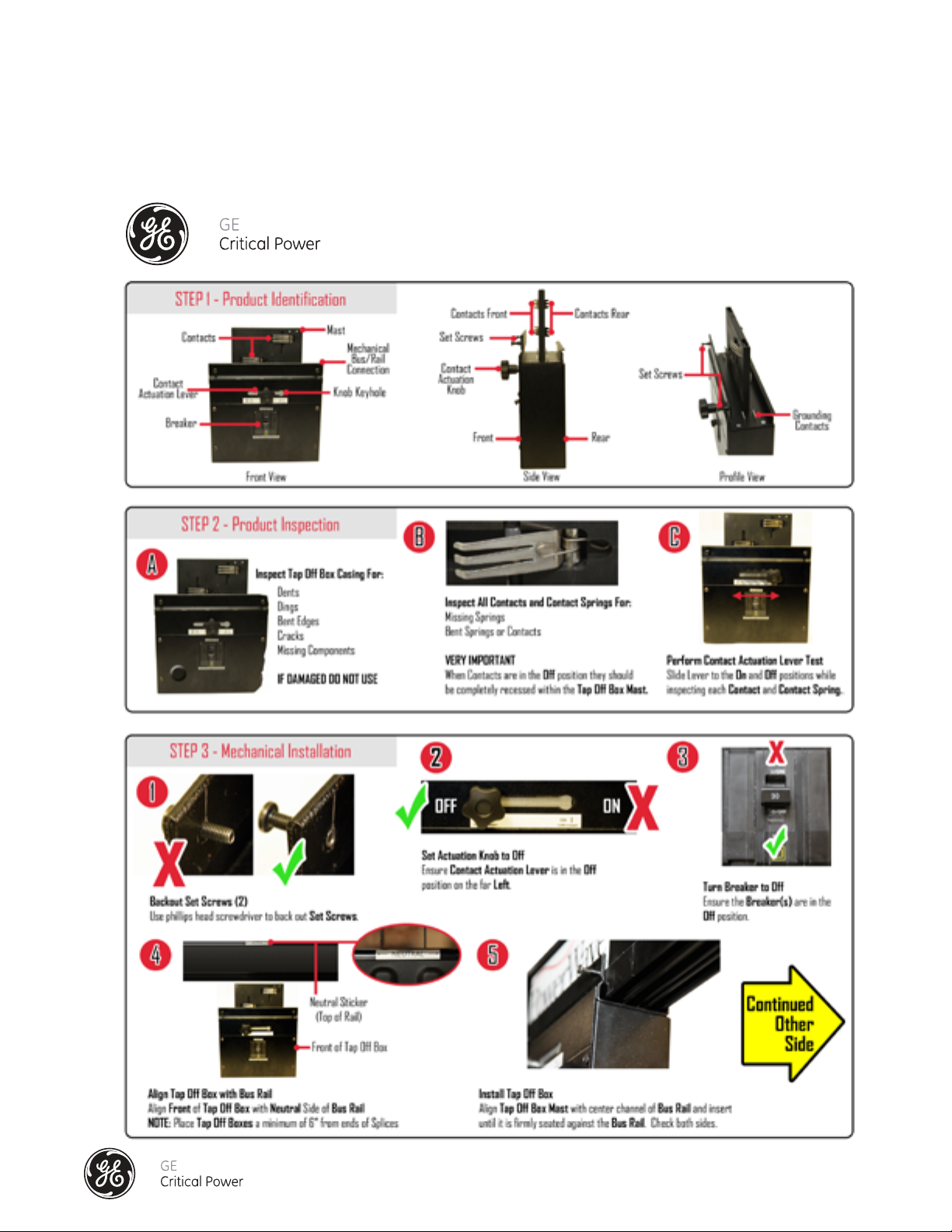
Series DPB Busway Installation & Operation Manual
TAP OFF BOX QUICK INSTALL SHEET
Installation & Operation Manual, GE Series DPB Busway
March 25, 2013, Rev 0
GE Confidential
92
 Loading...