

Page 1
GE Energy
Digital Energy
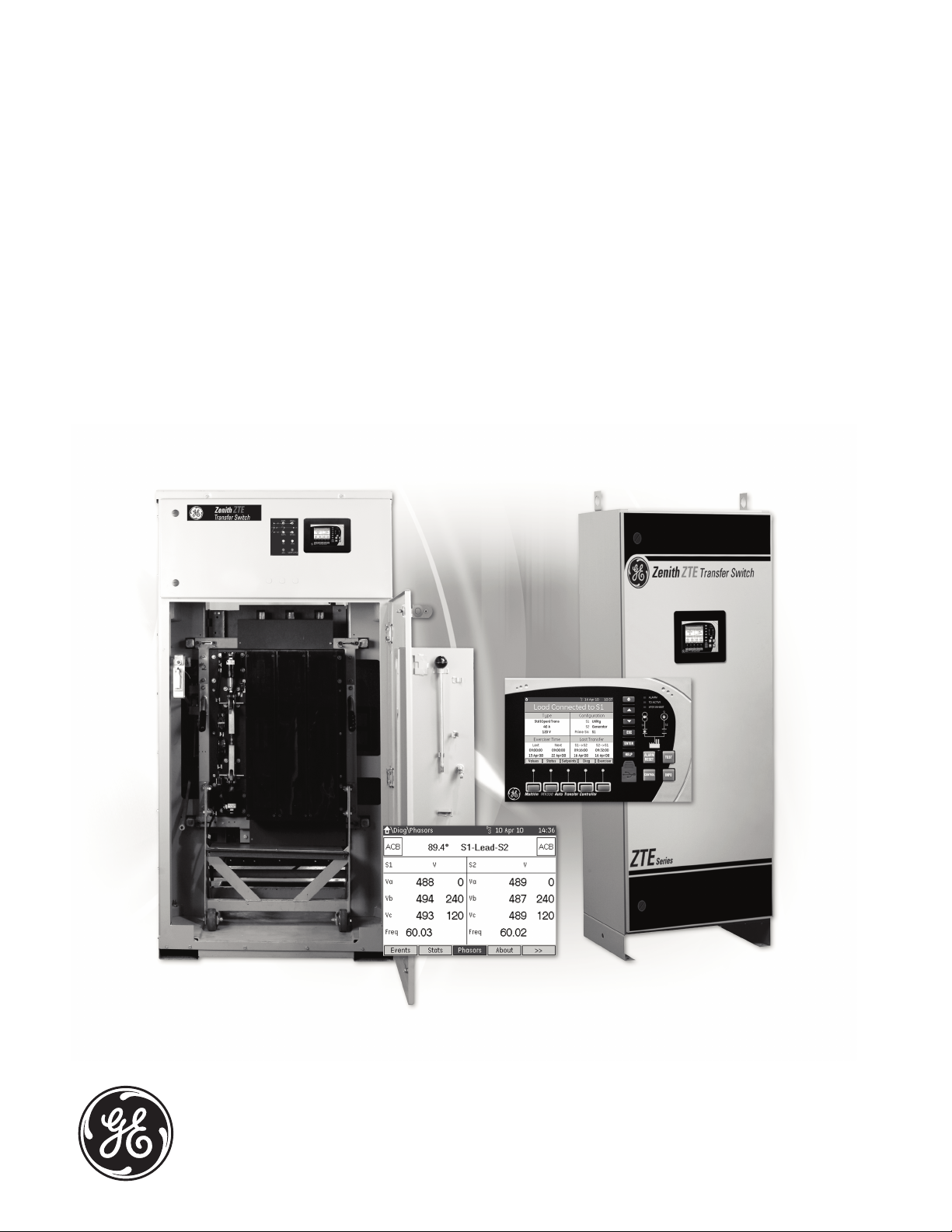
Zenith
ZTE/ZBTE Series
Transfer Switches
40-4000 Amps
Operation & Maintenance Manual
Page 2

Authorized Service
For GE parts and service call: 1 + 800 637-1738, option #3 or 1 + 773 299-6600
Table of Contents
Introduction, Safety & Storage . . . . . . . . . . . . . . . . . . . . . . . . . . . . . . . . . . . . . . . . . . . . . . . . . . . . . . . . . . . . . . . 1
Installation
Mounting . . . . . . . . . . . . . . . . . . . . . . . . . . . . . . . . . . . . . . . . . . . . . . . . . . . . . . . . . . . . . . . . . . . . . . . . . . . . . . . 2
Inspection Prior to Initial Energization . . . . . . . . . . . . . . . . . . . . . . . . . . . . . . . . . . . . . . . . . . . . . . . . . . . . 2
Initial Testing & Energization of the Switch
Manual Testing of Mechanism . . . . . . . . . . . . . . . . . . . . . . . . . . . . . . . . . . . . . . . . . . . . . . . . . . . . . . . . . . . 4
Electrical Testing of the Switch (Source 1 = utility, Source 2 = generator) . . . . . . . . . . . . . . . . . . . 5
The Control Connections . . . . . . . . . . . . . . . . . . . . . . . . . . . . . . . . . . . . . . . . . . . . . . . . . . . . . . . . . . . . . . . . . . . . . 5
The MX350 Controller
The MX350 Graphical Display & Keypad . . . . . . . . . . . . . . . . . . . . . . . . . . . . . . . . . . . . . . . . . . . . . . . . . . 7
Switch Exerciser. . . . . . . . . . . . . . . . . . . . . . . . . . . . . . . . . . . . . . . . . . . . . . . . . . . . . . . . . . . . . . . . . . . . . . . . . 9
Controller Power Supply (UTA – Universal Transformer Assembly) . . . . . . . . . . . . . . . . . . . . . . . . . . . . . . 9
Sequence of Operation . . . . . . . . . . . . . . . . . . . . . . . . . . . . . . . . . . . . . . . . . . . . . . . . . . . . . . . . . . . . . . . . . . . . . . 12
Sequence of Operation for Bypass/Isolation Transfer Switch . . . . . . . . . . . . . . . . . . . . . . . . . . . . . . . . . . 12
Troubleshooting & Diagnostics . . . . . . . . . . . . . . . . . . . . . . . . . . . . . . . . . . . . . . . . . . . . . . . . . . . . . . . . . . . . . . . 15
Maintenance & Testing . . . . . . . . . . . . . . . . . . . . . . . . . . . . . . . . . . . . . . . . . . . . . . . . . . . . . . . . . . . . . . . . . . . . . . 16
Notes . . . . . . . . . . . . . . . . . . . . . . . . . . . . . . . . . . . . . . . . . . . . . . . . . . . . . . . . . . . . . . . . . . . . . . . . . . . . . . . . . . . . . . . 17
Information subject to change without notice.
Please verify all details with
GE.
Page 3
Zenith ZTE/ZBTE Series Operation & Maintenance Manual
Page
1
91R-1000
Introduction, Safety & Storage
GE transfer switches are used to provide a continuous
source of power for mission, process and healthcare
critical loads by automatically transferring from a preferred source of power Source 1 (or Normal Source) to a
non-preferred alternate Source 2 (or Emergency) power
source (typically a generator) in the event that Source 1
operational parameters fall outside preset limits.
Voltage and current sensing and system controls are
performed via a state-of-the-art microcontroller located
on the cabinet door. It is designed to give highly accurate
control of the transfer switch system.
All GE transfer switches are designed for use on emergency
or standby systems and are rated for total system or motor
loads. Transfer switches are UL listed under Standard
1008 and CSA certified under Standard C22.2 No. 178.
The safe operation of your switch at all times is GE’s focus.
It must be recognized that hazardous voltages and
currents can exist during normal operation and any
maintenance on the transfer switch must be performed
utilizing appropriate safety measures. Installation,
adjustment, maintenance or removal of the switch must
only be carried out by qualified personnel with all power
to the switch turned off. It is recommended that only
qualified electricians be allowed to install or provide
maintenance on the switch.
Regarding the switch itself, proper storage, installation,
operation and maintenance will help increase its operational
life. Upon initial receipt of the transfer switch, inspect for
any damage. This includes damage to the enclosure, power
panel, control panel and wiring harnesses. If any damage
is found or suspected, file a claim as soon as possible
with the carrier and notify the nearest GE representative,
or call 1 + 800 637-1738 or 1 + 773 299-6600.
Prior to installation store the transfer switch in a clean dry
location, protected from dirt and water. Provide ample air
circulation and heat, if necessary, to prevent condensation.
See Table 1 for recommended storage and ambient
operating temperatures.
NOTE
A protective device such as a molded case circuit breaker or
fused disconnect switch MUST be installed on both sources of
incoming power for circuit protection and as a disconnect device.
All references made within this manual about the terms
“Source 1”, “S1” or “Preferred Source” relate to a “Normal”
power source (typically from a utility source). References made to
“Source 2”, “S2”, “Non-preferred Source” or “Alternate Source”
relate to an Emergency Source (many times a generator).
Table 1
Storage and Operating Ambient Temperatures
5% to 95%
(non-condensing)
-30°C to +75°C
(-22°F to +167°F)
40-400 AMP
(molded shell)
-20°C to +65°C
(-4°F to +149°F)
40-4000 AMP
(all other frame
and panel types)
-20°C to +60°C
(-4°F to +140°F)
Storage
Temperature
Humidity
Operating
Temperature
(Ambient)
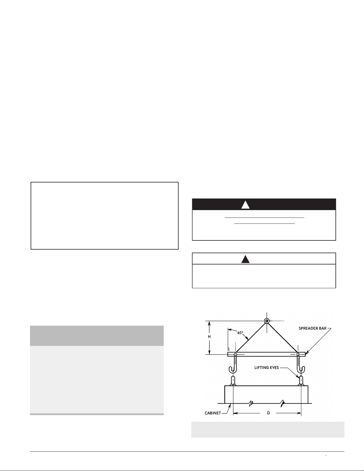
Figure 1
Method of Moving Transfer Switch
NOTE: When lifting the switch using a spreader bar, height H
must be equal to half of distance D.
!
DANGER
HAZARDOUS VOLTAGE CAN CAUSE
SEVERE INJURY OR DEATH
Turn OFF all power before installation, adjustment or
removal of transfer switch or any of its components.
!
CAUTION
Due to hazardous voltages and currents, GE recommends
that a GE Certified technician or a qualified electrician
perform the installation and maintenance of the switch.
Page 4
91R-1000 Page
2 Zenith ZTE/ZBTE Series Operation & Maintenance Manual
Installation
When preparing to install the transfer switch, review the
documentation included with the unit. Each GE transfer
switch is factory wired and tested. A complete documentation package is furnished with each switch, providing
descriptions and schematics for the following:
a. Standard and non-standard control interface
signals and options.
b. Sequence of operations.
c. Standard indicators, pushbuttons and annunciators.
d. Controller failure and return settings and time delays.
e. Description of the programmable engine exerciser.
f. Standard programmable control of switch operation.
g. User-configurable input and output.
h. System schematics:
1. Overall switch system.
2. Universal transformer assembly (UTA) power supply.
3. Transfer switch device layout.
4. Transfer switch power panel layout.
5. Interconnect plugs.
6. Customer connection wiring.
Mounting
Adequate lifting means must be used to mount the
transfer switch into place. The recommended method
for moving the ATS using lifting eyes, where supplied, and
a spreader bar is illustrated in Figure 1. Enough room
should be allowed to open the cabinet door(s) fully for
inspection and servicing of the switch per NEC and
local codes.
Inspection Prior to Initial Energization
Prior to energizing the transfer switch, perform the following:
1. With a vacuum, remove any debris collected on
the switch during shipment or installation.
2. Check engine start connections. The engine-start
terminals are located on terminal block positions
1 through 3 (see Figures 2 and 3). The E contact
provides the engine start signal from the automatic
transfer switch controller to the genset. The terminal
block has two sets of A3 (Source 2 position) normally
open contacts (NO) and two sets of A4 (Source 1
position) NO contacts.
3. Verify the correct connection of all control wires.
4. Check settings of all timers and adjust as necessary.
5. Adjust any optional accessories as required.
6. Verify that all Source 1, Source 2 and Load cables
are correctly connected to the clearly marked
terminals on the unit.
7. Verify from Table 2 the number and sizes of cable
lugs, which are supplied as standard per the switch
amperage rating. Most transfer switches are supplied with UL listed solderless screw-type terminals
as standard for the Source 1, Source 2 and Load
power connections.
8. Verify equipment ground cable(s) are installed per
NEC and/or local codes.
9. Verify that all cable lug connections are tightened
in accordance with torque values in Table 3.
10. Remove surface oxides from cables by cleaning
with a wire brush.
11. Make sure that all covers and barriers are installed
and properly fastened.
NOTE
Power panels ship from GE connected to Source 1.
NOTE
All control wires (18-12 AWG) must be
torqued to 19 in/lbs (1.6 lb-ft) (2.2 N-m)
Table 2
Power Connections: Screw Type Terminals for External Power Connections
Switch Size (Amps)
Source 1, Source 2 & Load Terminals Neutral Bar (When Required)
Cable Per Pole Range of Wire Sizes No. of Cables per lug Range of Wire Sizes
40 1 #8 AWG to 1/0 3 #8 AWG to 1/0
80 1 #8 AWG to 1/0 3 #8 AWG to 1/0
100 1 #8 AWG to 1/0 3 #8 AWG to 1/0
150 1 #8 AWG to 3/0 3 #8 AWG to 300 MCM
225 1 #6 AWG to 250 MCM 3 #6 AWG to 300 MCM
260, 400 1 #4 AWG to 600 MCM 3 #4 AWG to 300 MCM
600 2 #2 AWG to 600 MCM 8 #2 AWG to 600 MCM
800, 1000, 1200 4 #2 AWG to 600 MCM 12 #2 AWG to 600 MCM
1600, 2000, 3000, 4000 Line, Load and Neutral terminals are located in the rear of switch and arranged with bare bus bar
!
CAUTION
Before drilling conduit entry holes or any accessory mounting
holes, cover and protect the switch and control panel to
prevent dirt and metal fragments from entering the
mechanical and electrical components of the switch.
Failure to do so may result in damage and
malfunction of the switch and void the warranty.
Page 5
Zenith ZTE/ZBTE Series Operation & Maintenance Manual
Page
3
91R-1000
Table 3
Tightening Torque for Lugs
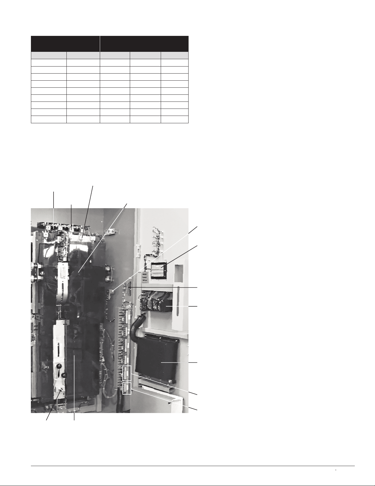
Figure 2
Typical Switch Component Arrangement Inside Enclosure
1200-1600A Bypass Shown Below
Terminal Block (
TB)
(Engine start contact terminals,
source 1 and 2 position contacts)
Input Relay (typ.)
Universal Transformer
Assembly (
UTA) Power Supply
ATS
Power
Panel
Backside of MX350
Graphical Control Panel
MX350 Modular Controller (
CPU, power
supply, sensing CT card, I/O cards, etc.)
Disconnect
Switch (DS)
Load
Current
Transformer (CT)
Block
Source 2
Source 1
Socket Size Across Flats Torque
in mm lb-in lb-ft N-m
1/8 3 45 4 5
5/32 4 100 8 11
3/16 5 120 10 14
7/32 5.5 150 12 17
1/4 6 200 17 23
5/16 8 275 23 31
3/8 10 375 31 42
1/2 13 500 42 56
9/16 14 600 50 68
Bypass Isolation
ATS Power Panel
Output Relay (typ.)
Page 6
91R-1000 Page
4 Zenith ZTE/ZBTE Series Operation & Maintenance Manual
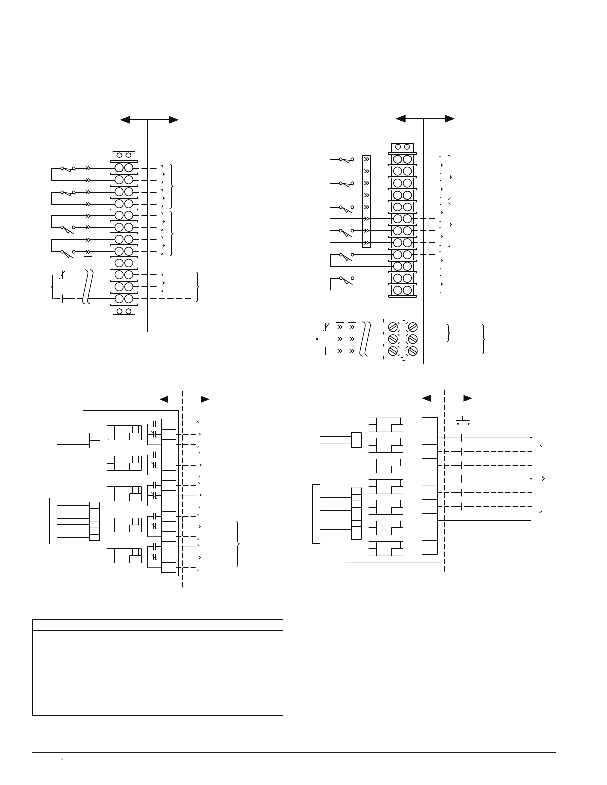
Figure 3
Representative Schematic of Terminal Board, Output Strip and Input Strip
Refer to Electrical Schematic Drawing for additional details
CUSTOMER USE
A1
OUT5
11
MX350 CONTROLLER
TO L-CARD SLOT “G” ON
G OUTPUT STRIP
OUTPUT-5
12A214
5-3
5-2
L5
L6
L4
L3
L2
L1
G2
G6
G4
G5
G3
J8
G1
800
802
J7
21-
+
OUTPUT-4
FACTORY USED (FOR ALARM)
FOR CUSTOMER USE
STATUS OUTPUT CONTACT
SHUNT TRIP EMERG. BKR.
LOAD SHED
STATUS OUTPUT CONTACT
FOR CUSTOMER USE
GE ZENITH
12
12
OUT4
A1
A2
OUT3
A1
A2
14
11
11
14
CONTROLS
12
12
A1
OUT1
OUT2
A2
A1
A2
11
14
11
14
802
4-2
4-3
5-1
4-1
3-3
3-2
2-3
3-1
1-3
2-2
1-2
2-1
1-1
(-)
OUTPUT
CONTACTS FOR
CONFIGURABLE
OTHERS
G INPUT STRIP
L9
MX350 CONTROLLER
TO L-CARD SLOT “G” ON
L13
L14
L12
L11
L10
G9
G13
G14
G12
G10
G11
L7
L8
802
800
J6
G8
G7
1
2
J5
-
+
(SUPPLIED BY OTHERS)
(SUPPLIED BY OTHERS)
(SEE NOTE 3)
(SEE NOTE 4)
(SEE NOTE 8)
CC
NO
12
12
12
IN7
A2
A1
IN5
IN6
A2
A1
A2
A1
14
11
14
11
14
11
COM
13
12
25ZA
NO
NO
CC
CC
IN1
11
A1
12
12
12
12
IN3
A1
IN4
A1
A2
A2
IN2
A1
A2
A2
11
11
14
14
11
14
14
GE ZENITH
CONTROLS
11
10
9
7
8
R15
NO
NO
CC
CC
Q2
DS
NO
C
FOR CUSTOMER USE
CONFIGURABLE INPUTS OPTION PACKAGE
OTHERS
COM
COM
CONNECTIONS OF THE TRANSFER SWITCH.
COMPONENTS DRAWN IN DASHED LINES ARE OPTION PACKAGE AND CUSTOMER
Q2 (TEST WITH LOAD) IS PROVIDED AS STANDARD (PRE-CONFIGURED) FEATURE.
R15 (LOAD SHED) IS PROVIDED AS AN OPTION (PRE-CONFIGURED) FEATURE.
ATS SHOWN IN SOURCE-1 POSITION WITH NO POWER AVAILABLE.
UNLESS OTHERWISE SPECIFIED ALL CUSTOMER CONNECTION WIRES TO BE #14 AWG.,
OUTPUT STRIP CONTACTS ARE RATED 10 AMPS AT 30VDC/250VAC.
ENGINE START CONTACT IS RATED 10 AMPS AT 28VDC/120VAC.
600V.
6.
7.
5.
4.
3.
2.
1.
NOTES
8. ENGINE START CONTACT MAY BE ON SEPARATE TERMINAL BLOCK FOR BYPASS
SWITCHES. REFER TO ELECTRICAL SCHEMATIC FOR TERMINAL LOCATION.
GE OTHERS
A4-1
A3-1
A3-2
CARD
8
K
8
C
C
C
7
9
E12
E11
E13
NO
NO
NO
A3-2
CA3-1
A3-1
CA4-1
A4-1
CA3-2
A4-2
C
AUX
NO
CA4-2
A4-2
CLOSED IN SOURCE 2 POSITION.
(2) NORMALLY OPEN CONTACTS.
FOR CUSTOMER USE.
FOR CUSTOMER USE
CONTACT
E
ENGINE START CONTACT
(2) NORMALLY OPEN CONTACTS
TB
FOR CUSTOMER USE.
HELD CLOSED IN SOURCE 1 POSITION
Non-Bypass ATS
Bypass ATS
8
K
CARD
8
9
7
A4-2
C
A4-1
C
A3-2
C
A3-1
C
AB4-5
C
AB3-6
C
PA3 T P1
GE OTHERS
TB
AUX
A4-2
NO
CA4-2
A4-1
NO
CA4-1
A3-2
NO
CA3-2
A3-1
NO
CA3-1
101
NO
100
99
NO
98
ENG. START
E11
E12
E13
(2) NORMALLY OPEN
CONTACTS, HELD CLOSED IN
SOURCE 1 POSITION FOR
CUSTOMER USE. SEE NOTE 1
(2) NORMALLY OPEN
CONTACTS, CLOSED IN
SOURCE 2 POSITION
FOR CUSTOMER USE.
CONTACT CLOSED WHEN BYPASS
IS IN SOURCE 1 POSITION.
FOR CUSTOMER USE.
CONTACT CLOSED WHEN BYPASS
IS IN SOURCE 2 POSITION.
FOR CUSTOMER USE.
E
CONTACT
ENGINE START CONTACT
FOR CUSTOMER USE
Page 7

Zenith ZTE/ZBTE Series Operation & Maintenance Manual
Page
5
91R-1000
Initial Testing and Energization of the Switch
Manual Testing of Mechanism
A manual operator handle is provided with the transfer
switch for maintenance purposes only. Manual operation
of the switch must be checked before it is operated
electrically. All power sources must be disconnected
before manual operation of the switch is attempted.
Insert the handle and operate the transfer switch between
the Source 1 and Source 2 positions. The transfer switch
should operate smoothly without binding. After insuring
the switch mechanically transfers adequately, return
the switch to Source 1 position, remove the handle
and return it to the holder provided.
Before proceeding, refer to the information package
supplied with the ATS. Read and understand the
information on all accessories installed.
Figure 4
Transfer Switch Equipment Rating Nameplate (Typical)
AUTOMATIC TRANSFER SWITCH FOR
USE
IN
EMERGENCY SYSTEMS
Model Number: Z3003S1AA50XXXXXXX
Serial Number: 1598248-2
BOM Number: ZB1SD20031-05A600X
RATING
Volts: 480 Hz: 60
Amps: 2000 Phase: 03
LISTED
382
H
E
23911
Electrical Testing of the Switch
(Source 1 = utility, Source 2 = generator)
To verify the electrical system and proper automatic
operation of the switch, perform the following steps:
CHECKING SOURCE 1 (PREFERRED SOURCE)
1. Check to make sure the switch is connected to
Source 1 position.
2. Turn the Disconnect Switch (DS) to INHIBIT. This
prevents the switch from transferring or sending a
start signal to the Source 2 generator unintentionally.
3. Verify that the switch rating is the same as the
system voltage from Source 1 supply power.
The equipment rating nameplate on the transfer
switch lists the voltage (see Figure 4).
4. Close the Source 1 input circuit breaker.
5. Confirm that the MX350 controller is sensing
Source 1 voltage. The S1 LED should be illuminated.
Electrical parameters (including phase rotation)
can be viewed on the MX350 Graphical Control
Panel on the \Value\Summary and \Diag\Phasor
screens. Verify that the system voltage is correct for
the rating of the switch.
CHECKING SOURCE 2 (NON-PREFERRED OR
ALTERNATE SOURCE)
6. Close the Source 2 input circuit breaker.
7. Manually start Source 2 via controls on the generator
itself. Note that with the DS in INHIBIT position, the
generator cannot be started by the MX350 controller.
8. Confirm that the MX350 controller is sensing
Source 2 voltage. The S2 LED should be illuminated.
Electrical parameters (including phase rotation)
can be viewed on the Graphical Control Panel on
the \Value\Summary and \Diag\Phasor screens.
9. Verify that the phase rotation of Source 1 is the
same as the phase rotation of Source 2.
10. Manually shut down the generator via controls on
the generator itself.
!
CAUTION
Due to hazardous voltages and currents, GE recommends
that a GE Certified technician or a qualified electrician
perform the installation and maintenance of the switch.
!
WARNING
All power sources must be disconnected
before manual operation of the switch.
!
CAUTION
Energizing a transfer switch with dissimilar
system voltage from that which the ATS
is rated may cause equipment damage.
Page 8

91R-1000 Page
6 Zenith ZTE/ZBTE Series Operation & Maintenance Manual
CHECKING THE SWITCH’S ABILITY TO TRANSFER
11. Turn the DS to AUTO position. This allows the MX350
controller to send a start signal to the generator.
12. Perform a System Test. The options available are
(a) Fast Test (test with load without time delays),
(b) Xfer Load and (c) No Xfer (test without load, gen-
erator start only). The test(s) can be initiated by the
green TEST button on the Graphical Control Panel.
13. After completing electrical tests, close and lock the
enclosure, including all small quarter-turn locks on
the enclosure door.
Electrical testing of the switch is further discussed in
the manual MX350 Automatic Transfer Control System
(Publication Number 1601-9071-A1).
The Control Connections
The ZTE and ZBTE lines of transfer switches are designed for
maximum flexibility and ease of installation. As illustrated in
Figure 2, the MX350 controller input/output and metering
modules, graphical control panel and power supplies
are mounted on the enclosure door. All terminal connections for the engine start, switch position contacts, input
and output relays are typically just inside the cabinet on
the right side for ease of accessibility. Configurable
input and output relays are PCB board mounted on DIN
rail in combinational arrays of 5 inputs and 7 outputs. A
“Field Connection Diagram” (see the example in Figure
5) is affixed on the cover of the universal transformer
assembly (
UTA) power supply for easy reference. This
diagram provides the factory-supplied terminal board
connections as well as dry contact inputs and outputs
identified by terminal number as defined in the MX350
controller. The terminal board and I/O connections are
schematically shown in Figure 3. Close-up photographs
of an input and output PCB with terminal connections
are shown in Figures 6 and 7.
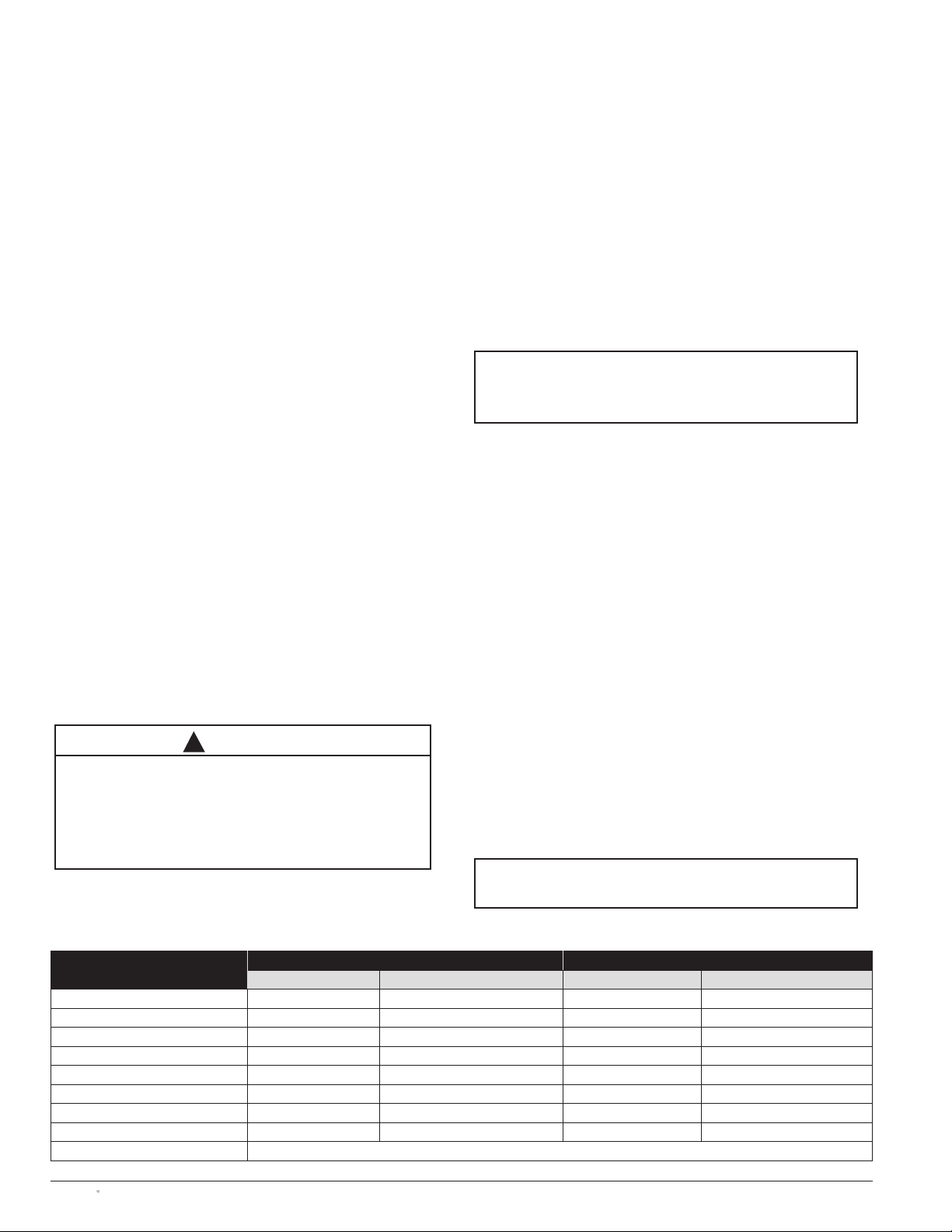
The number of PCB-mounted input and output relay
assemblies equals the number of “L cards” on the
microcontroller, more formally termed “IO_L modules.”
The assembly of output relays is GE part number 50P-3042.
The input relay assembly is GE part number 50P-3041. If
the microcontroller has one L card, then there will be
one pair of
GE Part Number 50P-3041 and 50P-3042 PCB
combinations mounted on the DIN rail inside the enclosure.
For two L cards, there will be two sets of input and output
strips. The maximum combination is three pairs of I/O
strips (that is, a total of six relay DIN rail mounted PCBs).
The controller automatically recognizes the physical
location of the input or output relays via an alpha-numeric
identification system. The first set of output relays are
named G1 through G5 while the input relays are identified
as G7 through G13. If a second L card exists in the microcontroller, the second PCB-mounted assembly output relays
are named H1 through H5; the outputs are H7 through
H13. Similarly, a third IO_L module is related to inputs
I1 through I5 and outputs I7 through I13 (see Table 4).
NOTE
A periodic test of the transfer switch under load conditions
is recommended to insure proper operation.
(See National Electric Code articles 700 and 701)
Terminal Terminal Terminal Type
G1 H1 I1 Output
G2 H2 I2 Output
G3 H3 I3 Output
G4 H4 I4 Output
G5 H5 I5 Output
G6 H6 I6 Common for outputs
G7 H7 I7 Input
G8 H8 I8 Input
G9 H9 I9 Input
G10 H10 I10 Input
G11 H11 I11 Input
G12 H12 I12 Input
G13 H13 I13 Input
G14 H14 I14 Common for inputs
Table 4
IO_L Module Connections
Terminals G7 and G8 are always used for DS and Q2 functions, respectively, and cannot
be adjusted. Depending on the type of switch and features ordered, Terminals G1 through
G5 as well as G9 through G13 may not be available for customer configuration. See
electrical schematic.
!
CAUTION
Certain accessories, per specific schematics, can inhibit
automatic transfer. Engine Genset could start when engine
control wires are attached.
Page 9

Zenith ZTE/ZBTE Series Operation & Maintenance Manual
Page
7
91R-1000
Figure 5
Example of Field Connection Diagram
Notes: 1. See Field connection wiring diagram for additional wiring details.
2. Controller inputs and outputs are field reconfigurable. “Factory Settings: indicate configuration at time of shipment.
3. From MX350 Display, go to \HOME\INPUTS or \HOME\OUTPUTS to see current configuration.
4. Record user configuration in “Field Setting” area below.
Name Term # Description
TB Strip 15 Connected to Source 1 (NO)
14 Connected to Source 1 (Common)
13 Connected to Source 1 (NO)
12 Connected to Source 1 (Common)
11 Connected to Source 2 (NO)
10 Connected to Source 2 (Common)
9 Connected to Source 2 (NO)
8 Connected to Source 2 (Common)
7
6
5
4
3 Engine Start – NC
2 Engine Start – Common
1 Engine Start – NO
G Input
Strip
G 7 Disconnect Switch (DS)
Factory Use
Only
G 8 Test with Load (Q2)
Factory Use
Only
G 9 Load Shed from S2 (R15)
Factory Use
Only
G 10 Bypass Xfer Time Delay to S1
G 11 Inhibit Xfer to S2 (Q3)
G 12 Inhibit Xfer to S1 (Q7)
G 13 Engine Start (SW1)
Com +24VDC
Factory Use
Only
Name Term # Factory Setting Field Setting
G Output
Strip
G 1 (NO/NC/
Common)
Load Shed from S2 (R15)
Factory Use
Only
G 2 (NO/NC/
Common)
Alternative Source Fail to Start
G 3 (NO/NC/
Common)
S1 Failure
G 4 (NO/NC/
Common)
S2 Failure to Connect
G 5 (NO/NC/
Common)
Load Control 1
Name Term # Description
TB Strip 12 Connected to Source 1 (NO)
11 Connected to Source 1 (Common)
10 Connected to Source 1 (NO)
9 Connected to Source 1 (Common)
8 Connected to Source 2 (NO)
7 Connected to Source 2 (Common)
6 Connected to Source 2 (NO)
5 Connected to Source 2 (Common)
4 Bypass in Source 1 (NO)
3 Bypass in Source 1 (Common)
2 Bypass in Source 2 (NO)
1 Bypass in Source 2 (Common)
3 Engine Start – NC
2 Engine Start – Common
1 Engine Start – NO
Non-Bypass ATS
Bypass ATS
Page 10

Input 7
Position 1
Input 8
Position 2
Input 9
Position 3
Input 10
Position 4
Input 11
Position 5
Input 12
Position 6
Input 13
Position 7
Common
Position 8
Common
Position 9
Common
Position 10
91R-1000 Page
8 Zenith ZTE/ZBTE Series Operation & Maintenance Manual
Output 1
1 = NO
2 = NC
3 = common
Output 2
4 = NO
5 = NC
6 = common
Output 3
7 = NO
8 = NC
9 = common
Output 4
10 = NO
11 = NC
12 = common
Output 5
13 = NO
14 = NC
15 = common
Figure 7
Input Strip and Connections (GE Part Number 50P-3041)
Figure 6
Output Strip and Connections (GE Part Number 50P-3042)
Page 11

Zenith ZTE/ZBTE Series Operation & Maintenance Manual
Page
9
91R-1000
Figure 8
MX350 Graphical Display Components
The MX350 Controller
The MX350 microcontroller is a modular control and
monitoring system designed specifically for low-voltage
transfer switch applications. The MX350 provides the
following key benefits:
• Flexible control and communication options to suit
any low-voltage transfer switch application.
• Small footprint.
• Modular design, which reduces the number of spare
components for maintenance and testing.
• Integrated pushbuttons and LED indicators which
reduce required external components and wiring
• Multiple communication protocols which permit simple
integration into monitoring and control systems.
• A graphical control panel that provides local control
and access to system information.
Detailed technical information on the MX350 controller
is described in the manual MX350 Automatic Transfer
Control System (Publication Number 1601-9071-A1).
The MX350 Graphical Display and Keypad
The MX350 controller features a ¼ VGA color graphical
display with status LEDs, an USB programming port and
menu-driven soft keys (see Figure 8) as well as dedicated
control and navigational keys. Each display page, in
turn, consists of three components: (1) a header bar,
(2) the selected page and (3) soft-key labels (Figure 8).
The header bar displays the hierarchical path name, the
date and time and the current password access level.
The soft-key labels are indicated on the bottom line.
Soft-keys are used for navigation, performing functions
and for acknowledgement transactions. Soft-keys labels
change to show relevant selections for the displayed
screen. The color of each soft-key label indicates its
functionality. Soft-keys are highlighted for the displayed
page, unauthorized keys are “greyed-out”, and unused
keys are not displayed.
The control panel LEDs summarize the status of the
transfer switch, including the following indications:
• ALARM: indicates that there is a problem with the ATS
or that a user configurable alarm condition is active.
• TD DELAY: indicates that the controller is timing before
taking the next control action.
• XFER INHIBIT: indicates that the controller will not
automatically transfer to the other source and that
operator intervention is required to allow transfer.
• S1 (Source 1) Available LED: indicates that S1 power
is present and within user defined limits.
• S2 (Source 2) Available LED: indicates that S2 power
is present and within user defined limits.
• S1 (Source 1) Status LED: indicates that the load is
connected to S1 power.
• S2 (Source 2) Status LED: indicates that the load is
connected to S2 power.
The MX350 controller page hierarchy is shown in Figure 9.
Operation Setpoints and
User-Configurable Inputs and Outputs
Operation setpoints define the acceptable electrical and
time limits for both Source 1 and Source 2. These setpoints define dropout and restore values for over and
undervoltage, over and under frequency, as well as the
associated time delays. Tables 7 and 8 provide typical
parameter settings for operation setpoints and timers.
Page 12

91R-1000 Page
10 Zenith ZTE/ZBTE Series Operation & Maintenance Manual
Figure 9
MX350 Graphical Display Page Hierarchy
Values
Status
Setpoints
Summary
Amps
Volts
Power
PQ
Message
Inputs
Outputs
System
Flex
Config
Reset
Summary
V1 Harm
V1 Harm
V2 Harm
V2 Harm
IHarm
IHarm
Summary
V Inputs
V Outputs
Phase A
Phase B
Phase C
Phase A
Phase B
Phase C
Phase A
Phase B
Phase C
ATS
Diag
Exerciser
Operation
Control
Security
Events
Stats
Phasors
About
Report
Waveform
Datalog
Info
Setup
Reset
S1 Setting
S2 Setting
Timers
General
Interlock
Alarms
CT-VT
Inputs
Outputs
Comms
System
Events
Zenith
Waveform
Datalog
Alarms
Faults
Control
Virtual
Main menu
Test
ExerCancel
Level 3Level 2Level 1
Page 13

Zenith ZTE/ZBTE Series Operation & Maintenance Manual
Page
11
91R-1000
Switch Exerciser
The MX350 controller has a built-in exerciser that can
be enabled and set up from the \Exerciser\Info screen.
This feature allows the user to test the system periodically or to setup a schedule for operating the system
periodically in order to minimize utility costs.
From the \Exerciser\Info screen the operator can access
all required setup parameters for scheduling exercises.
It also indicates as to when the last exercise took place
and when the next exercise will be performed.
The \Home\Exerciser\Setup page displays the MX350
Exerciser parameters as shown in Figure 10. Exercise type
and schedule are user-defined here for starting time,
duration of exercise and whether or not the switch is to
transfer the load. The mode of operation of the exerciser
function can be selected with a time base of 1 day, 1 week,
14 days, 28 days, or 365 days. With a time base of 365
days, up to 24 events can be scheduled. With all other
time bases, the number of exercise events is limited to 7.
Figure 10
Exerciser Values on Home\Exerciser\Setup Page
For each exercising event, the operator enters a start time
as well as a time of duration. In addition, the operator can
select the type of exercise as ‘Genstart and Transfer’ or
as ‘Genstart only’. When the ‘Gen Start only’ mode is
selected, the controller will start the engine, but does not
actually transfer the load. In this mode, the readiness for
the engine generator set is tested. It does not test the
functionality of the Automatic Transfer Switch itself. In
the ‘Gen Start and Transfer’ mode, the controller starts
the engine and actually transfers the load to the alternative source. This mode can be used to test the integrity
of the emergency power system. It can also be used to
setup a schedule for times of operation when the switch
load will run on an alternative power supply. This could
be done, e.g., to avoid demand charges from a utility
company. If the operator chooses to abort an ongoing test,
there is a ‘Test Cancel’ button on the \Exerciser\Info
screen. This screen also contains a ‘Test’ button that
will take the user directly to the Test screen.
The \Home\Exerciser\Test page displays the MX350
system test choices, as shown in Figure 11. From the
Test screen the user can perform the same operations
as performed by the exerciser. Whereas exercises are
performed automatically, a Test always has to be
initiated by the user.
Figure 11
System Test Choices on Home\Exerciser\Test Page
There are three types of tests: Fast Test, Xfer Load, and
No Xfer. The screen also provides an END button to abort
any of the three test types. To test the functionality of
the switch the operator can use the Fast Test option.
With this kind of test, the engine generator will start
and the load will transfer without going through any
time delays. In order to simulate a load transfer as if an
outage was occurring, the operator can select the Xfer
Load test. With this test type, the engine will start up
and the load will transfer according the time delay of
the W timer. When the test is ended (by depressing the
END button), the switch will go through the U timer
delay before actually transferring back to the utility.
Controller power supply
(UTA – universal transformer assembly)
System line voltage is transformed to 170Vdc to power
the MX350 controller and 24Vdc ungrounded to power
relays via the universal transformer assembly (UTA).
The power supply is termed “universal” because the same
unit handles all line voltages from 120Vac through
600Vac via an internal six-position jumper array. Figure 12
shows the external connections points for the UTA. The
UTA also features a 120Vac uninterruptible power supply
input and 24Vdc input battery options. 120Vac and
24Vdc (ungrounded) must be supplied together from an
uninterrupted power source. In addition, test terminals
are included for transformer voltage monitoring (see
Figure 13 for connection point definitions and Figure 14
for the UTA schematic).
Page 14

91R-1000 Page
12 Zenith ZTE/ZBTE Series Operation & Maintenance Manual
Figure 12
Connection Points for Universal Transformer Assembly (UTA)
Figure 13
Connection Points on Test Plug for Universal Transformer Assembly (UTA)
120VAC Aux Input
(customer supplied) (not obligatory)
(See Note 1)
24VDC output from
UTA to I/O relays
170VDC output
from UTA to
MX350 controller
Source 1
voltage input
Test points
Source 2
voltage input
24VDC Aux Input (ungrounded)
(customer supplied) (not obligatory)
(See Note 1)
Plug position
Test point
Plug position
Test point
20
TP1
19 18
TP3
17 16
TP5
15 14
TP7
13 12
TP9
11
10 9
TP2
8 7
TP4
6 5
TP6
4 3
TP8
2 1
TP10
Plug position Test point Test Connection Points Value Measured
1 TP10 TP1-TP2 Line AC voltage input from Source 1
2 — TP2-TP3 Voltage drop across R1
3 TP8 TP4-TP5 24 VAC to output from Source 1 to input/output relays
4 — TP6-TP7 Line AC voltage input from Source 2
5 TP6 TP7-TP8 Voltage drop across R2
6 — TP9-TP10 24 VAC to output from Source 2 to input/output relays
7 TP4
8—
9 TP2
10 —
11 —
12 TP9
13 —
14 TP7
15 —
16 TP5
17 —
18 TP3
19 —
20 TP1
View looking into plug
UTA
metal
cover
UTA PC board
Note 1: Both Aux inputs must be supplied from an uninterrupted power
source. Supplying only one Aux input may result in malfunction.
Page 15

Zenith ZTE/ZBTE Series Operation & Maintenance Manual
Page
13
91R-1000
Figure 14
Universal Transformer Box Assembly (UTA) Schematic
J1
V_A
20
1
REFER TO
ELECTRICAL
SCHEMATIC DWG.
SHEET 4
TEST POINTS
FOR SERVICE
TROUBLESHOOTING
Source 1
AC Voltage
Source 2
AC Voltage
3
V_B
21
J2
V_A
30
1
3
31
V_B
J3
20
10
20
9
18
7
16
5
14
3
12
1
1
11
TO TP1
TO TP2
TO TP3
TO TP4
TO TP5
TO TP6
TO TP7
TO TP8
TO TP9
TO TP10
MOV1
MOV2
120VAC
120VAC
17VDC
120VAC
120VAC
17VDC
TP2
TP1
TP5
D25
TP4
TP3
R1
~
D1
D5
D2
D6
+
-
D7
D3
D8
D4
TP10
3
1
JP6
TP1
TP2
TP1
TP3
TP2
0
TP3
TP4
TP5
TP6
TP7
TP6
TP8
TP7
0
TP8
TP9
TP10
JP5
JP4
JP3
JP2
JP1
12
10
T1
7
6
5
4
3
2
1
7
9
7
11
12
T2
9
FROM
CUSTOMER
UPS (120VAC)
OPTIONAL FOR KEEPING
THE MX350 CPU ACTIVE
WITH LOSS OF SOURCE 1
OR SOURCE 2 POWER
(SEE NOTE 1)
170-
TO MX350
CONTROLLER
POWER SUPPLY (PS)
170+
802
FROM
TO MX350
CONTROLLER
I/O’S
800
FROM
CUSTOMER
BATTERY
(24VDC)
(UNGROUNDED)
J12
J9
J4
6
D17
J6
1
3
R5
V_A
MOV3
V_B
-
2
+
4
-
1
+
2
D21
D18
D22
+
-
D23
D19
D24
D20
R3
R4
5
4
3
2
1
7
TP7
R2
TP9
TP8
~
D9
D10
D25
D13
D14
+
-
D16
11
12
TP6
C2
C1
D12
D4
D8
MOV4
MOV5
D26
+
1
-
2
OPTIONAL FOR KEEPING THE INPUT AND OUTPUT STRIPS ACTIVE WITH
LOSS OF SOURCE 1 OR SOURCE 2 POWER (SEE NOTE 1)
NOTE 1: MUST BE SUPPLIED TOGETHER FROM AN UNINTERRUPTED POWER SOURCE
Page 16

91R-1000 Page
14 Zenith ZTE/ZBTE Series Operation & Maintenance Manual
Sequence of Operation
Automatic transfer switches transition from one source
to a second source in three different ways: standard
(also referred to as open), delayed and closed transition.
Delayed transition switches have an intermediary midpoint location where the switch is not connected to either
source when transferring to the non-preferred source
after a preferred source failure. For closed transition, both
sources are connected momentarily. Timers are utilized
to insure that sources are stable before transferring or
to prevent a hurried, ultimately unnecessary transfer
when the apparently failed source was actually not in
a state of failure.
When transferring with two good sources (either a
retransfer back to Source 1 or a system test transfer),
closed transition switches are momentarily connected
to both sources for a period of less than 100 ms. The
controller prevents transfer until Source 2 is in electrical
synchronism with the utility.
Sequence of Operation for
Bypass/Isolation Transfer Switch
An automatic transfer switch equipped with a bypass/
isolation switch provides the ability to withdraw the
automatic transfer switch for testing and/or maintenance
purposes without interrupting the served load. The bypass
manual switch is the upper power panel while the
automatic switch is housed in the lower panel (see
Mimic Bus and Indicator Lights Schematic in Figure 15).
Operation of the unit is quick and convenient, requiring
only one operator and less than one minute to complete.
Instructions are mounted on the front of each isolation
switch door along with a mimic panel providing indication
of power source availability and bypass/ATS switch
positions.
The manual bypass switch is normally open on both
sources with the ATS feeding the system load. During
operation, the bypass switch is closed, paralleling the
ATS contacts which then allows withdrawal of the ATS to
the TEST or ISOLATE position. Mechanical and electrical
interlocks are included to prevent cross-sourcing or
bypassing to a dead source.
In the TEST position, the ATS is disconnected from the
load (which is instead powered through the bypass
panel). However, control power is available to the ATS
to permit operational testing through the control panel
of the transfer switch while removed from Source 1
and Source 2.
In the ISOLATE position, the ATS is completely withdrawn
and may be removed from the enclosure, if desired, for
maintenance.
After the isolation operation, if the bypass is closed into
Source 1 and this source happens to fail, an auxiliary
contact on the bypass control will automatically start
the alternate generator source (Source 2). The manual
handle of the bypass may then be operated to transfer
the load to Source 2. Interlocks guard against inadvertent
manual connection to an opposite source if the ATS is in
the circuit. Also, the reconnection of the ATS is prevented
via interlocks if the source positions don’t match.
Comparative sequences of operation for bypass/isolation
transfer switch as a function of rated amperage are
shown in Figure 16.
Figure 15
Bypass/Isolation
Transfer Switch
Mimic Bus and
Indicator Lights
Schematic
!
WARNING
While the bypass switch is out of the AUTO position/mode, the
ATS is INHIBITED from automatic operation. Make certain the
ATS is left in automatic after completion of any service.
Page 17

Zenith ZTE/ZBTE Series Operation & Maintenance Manual
Page
15
91R-1000
Vertical Vertical Horizontal Vertical Horizontal
Vertical
100-400A 600-1200A 1600-3000A
4000A Switch Position Switch Position
1.
Configuration
for
Automatic
Operation
• Manually operated Bypass Switch
contacts (BN/BE) are open
• ATS is supplying load
• Disconnect switch (DS) is in AUTO
• Manually operated Bypass Switch contacts
(BN/BE) are open
• ATS is supplying load
• Disconnect switch (DS) is in AUTO
• Manually operated Bypass Switch
contacts (BN/BE) are open and ATS
is supplying load
• Disconnect Switch (DS) is in Auto
• Manually operated Bypass Switch
contacts (BN/BE) are open
• ATS is supplying load
• Disconnect switch (DS) is in AUTO
2.
To Bypass
ATS
• Open bottom cabinet door
• Turn Disconnect Switch (DS)
to INHIBIT
• Position manual bypass handle (MBH)
to same power source at ATS
• Open bottom cabinet door
• Turn Disconnect Switch (DS) to INHIBIT
• Turn Bypass Selector Switch (BSS) to same
power source as ATS
• Turn DS to Inhibit
• Open Bypass Isolation Access panel
• Turn Bypass Selector Switch (BSS) to
same power source as ATS
• Position Manual Bypass Handle
(MBH) upward
• Open bottom cabinet door
• Turn Disconnect Switch (DS) to INHIBIT
• Position manual bypass handle (MBH)
upward
3.
To Test
ATS
• Bypass per instruction #2 above
• Move ATS location handle (ALH)
to TEST location
• Turn DS to AUTO
• Test switch (TS) on bottom
cabinet door will allow
electrical operation of ATS
• Bypass per instruction #2 above
• Rotate crank mechanism counter-clockwise
until ATS TEST light is illuminated
• Turn DS to AUTO
• Test switch (TS) on bottom cabinet door
will allow electrical operation of ATS
• Bypass per above instructions
• Rotate crank mechanism counter-clock-
wise until ATS TEST light is illuminated
• Turn DS to Auto
• Test Switch (TS) on microprocessor
controller will allow electrical
operation of ATS
• Bypass per instruction #2 above
• Rotate crank mechanism counter-clock-
wise until ATS TEST light is illuminated
• Turn DS to AUTO
• Test switch (TS) on bottom cabinet door
will allow electrical operation of ATS
4.
To Isolate
ATS
• Bypass per instruction #2 above
• Move ATS location handle (ALH)
to ISOLATE position
• Bypass per instruction #2 above
• Rotate crank mechanism counter-clockwise
until ATS ISOLATED light is illuminated
(See Figure 15)
• Bypass per above instructions
• Rotate crank mechanism counter-
clockwise until ATS
ISOLATED light is illuminated
• Bypass per instruction #2 above
• Rotate crank mechanism counter-
clockwise until ATS ISOLATED light
is illuminated (See Figure 15)
5.
To Remove
ATS
• Bypass per instruction #2
and isolate per #4 above
• Move ATS location handle (ALH)
to RELEASE position
• Disconnect multipin plugs
• Lift ATS out of drawer
• Bypass per instruction #2 and isolate per #4 above
• Disconnect multipin plugs & external
connections to ATS
• Rotate four (4) power panel latches to vertical
position, slide ATS forward & lock mechanism
in place
• Remove ATS from cabinet
• Bypass and isolate per above
instructions
• Open Automatic Transfer Switch
access panel
• Slide four corner latches of ATS to
innermost position
• ATS can now be removed from cabinet
• Bypass per instruction #2 and isolate
per #4 above
• Disconnect multipin plugs & external
connections to ATS
• Slide for (4) corner latches of ATS to
innermost position
• Remove ATS from cabinet
6.
To Reconnect
ATS After
Removal
• Place ATS into drawer slots
(front rollers first)
• Turn Disconnect Switch (DS) to INHIBIT
• Manually position ATS into same
source as bypass switch
• Reconnect multipin plugs & external
connections to ATS
• Push ATS inward to engage carriage
• Move ATS location handle (ALH) to
TEST location (as indicated by light)
• Turn Disconnect Switch (DS) to
AUTO & use Test Switch (TS) to
electrically operate ATS
• Turn Disconnect Switch (DS) to INHIBIT
• Move ATS location handle (ALH) to
AUTO location
• Turn DS to AUTO & open bypass
with MBH
• ATS is now fully automatic
• Place ATS in slide mechanism
• Unlock slide mechanism
• Slide ATS over power panel latches &
rotate latches to horizontal position
• Turn Disconnect Switch (DS) to INHIBIT
• Manually position ATS into same source as
bypass switch
• Reconnect multipin plugs & external
connections to ATS
• Rotate crank mechanism clockwise until
ATS TEST light is illuminated (See Figure 15)
• Turn Disconnect Switch (DS) to AUTO & use
Test Switch (TS) to electrically operate ATS
• Turn Disconnect Switch (DS) to INHIBIT
• Rotate crank mechanism clockwise until ATS
location pointer is aligned with AUTO mark on location
indicator. (ATS must be in same source as bypass)
• Turn DS to AUTO & open bypass with manual
bypass handle (MBH)
• ATS is now fully automatic
• Roll cart back into cabinet
• Slide four corner latches of
ATS to outermost position
• Turn DS to Inhibit
• Manually position ATS into
same source as Bypass Switch
• Close Automatic Transfer Switch
access panel
• Rotate crank mechanism clockwise
until ATS Test light is illuminated
• Turn DS to Auto and use TS to
electrically operate ATS
• Turn DS to Inhibit
• Rotate crank mechanism clockwise
until ATS location pointer is aligned
with Auto mark on location indicator.
(ATS must be in same source as Bypass)
• Turn DS to Auto and open
Bypass with MBH
• ATS is now fully automatic
• Roll ATS cart back into cabinet
• Slide four (4) corner latches of ATS to
outermost position
• Turn Disconnect Switch (DS) to INHIBIT
• Manually position ATS into same source
as bypass switch
• Reconnect multipin plugs & external
connections to ATS
• Rotate crank mechanism clockwise until
ATS TEST light is illuminated (See Figure 15)
• Turn Disconnect Switch (DS) to AUTO & use
Test Switch (TS) to electrically operate ATS
• Turn Disconnect Switch (DS) to INHIBIT
• Rotate crank mechanism clockwise until
ATS location pointer is aligned with AUTO
mark on location indicator. (ATS must be
in same source as bypass)
• Turn DS to AUTO & open bypass with
manual bypass handle (MBH)
• ATS is now fully automatic
7.
To Operate
the Bypass
Switch When
the ATS is in
TEST or
ISOLATE
• Move the manual bypass
handle (MBH) to the available
power source
• (1) Move manual bypass handle (MBH) downward
to open the bypass power panel contacts,
• (2) turn the bypass selector switch (BSS) to the
opposite power source, and
• (3) move the MBH upward to close into the
selected power source
• (1) Move manual bypass handle
(MBH) downward to open the
bypass power panel contacts,
• (2) turn the bypass selector switch (BSS)
to the opposite power source, and
• (3) move the MBH upward to close
into the selected power source
• (1) Move manual bypass handle (MBH)
downward to open the bypass power
panel contacts,
• (2) turn the bypass selector switch (BSS)
to the opposite power source, and
• (3) move the MBH upward to close
into the selected power source
Notes:
• Disconnect Switch (DS) in INHIBIT prevents the electrical operation of the ATS.
• Do not use excessive force on mechanical handles.
• Figures depict bypass operations relative to Source 1. Sequences are the same for bypass operations relative to Source 2.
• When ATS is in TEST or ISOLATE, the bypass switch operates as a manual transfer switch to either available source, which is indicated on the light panel. (See Figure 15)
FIG. 1 BP IS OPEN WITH ATS IN SOURCE 1
ATS
BN
BE
SOURCE 1
LOAD
SOURCE 2
FIG. 2 BP IN SOURCE 1 WITH ATS IN SOURCE 1
ATS
BN
BE
SOURCE 1
LOAD
SOURCE 2
FIG. 3 BP IN SOURCE 1 WITH ATS IN TEST
(LOAD CONNECTIONS ARE OPEN)
ATS
BN
BE
SOURCE 1
LOAD
SOURCE 2
FIG. 4 BP IN SOURCE 1 WITH ATS ISOLATED
ATS
BN
BE
SOURCE 1
LOAD
SOURCE 2
Figure 16
Sequence of Operation for Bypass/Isolation Switches
Page 18

91R-1000 Page
16 Zenith ZTE/ZBTE Series Operation & Maintenance Manual
Symptom Possible Cause(s) Corrective Action
Engine does not start
Engine start wires not terminated properly Check engine start connections
Generator is in OFF position
Investigate why Engine Control Switch was
turned off
Engine does not stop
U timing cycle not complete Check U timer setting
Engine start wires not terminated properly Check engine start connections
Generator in MANUAL Place generator in AUTO
Source 1 not within proper parameters
Check Source 1 voltage, frequency values,
and Source 1 circuit breaker
ATS will not transfer
to Source 2
Mechanical or electrical connections problem
Check all connections to SCR modules, check DS
for proper operation & wire connections, check limit
switches for proper operation
Remote active inhibit signal Check for remote inhibit signal
Source 2 voltage or frequency not with acceptable
parameters
Check engine start connections, generator breaker,
generator output & engine control switch
Power supply connector unplugged Plug in connector
W timing cycle not complete Check W timer setting
ATS will not transfer
to Source 1
Mechanical or electrical connections problem
Check all connections to SCR modules, check DS
for proper operation & wire connections, check limit
switches for proper operation
Remote inhibit active Check for remote inhibit signal
DW timing cycle not complete Check DW timer setting
Source 1 voltage or frequency not within
acceptable parameters
Check utility & utility breakers
Power supply connector unplugged Plug in connector
T timing cycle not complete Check T timer setting
Troubleshooting & Diagnostics
The following troubleshooting guide may be used to recognize and determine basic faults.
If you go through all of the suspected faults and still require assistance, call a GE technical representative.
Table 5
Basic Troubleshooting Guide for Automatic Transfer Switches
!
DANGER
HAZARDOUS VOLTAGE CAN CAUSE
SEVERE INJURY OR DEATH
Turn OFF all power before installation, adjustment or
removal of transfer switch or any of its components.
Page 19

Zenith ZTE/ZBTE Series Operation & Maintenance Manual
Page
17
91R-1000
Maintenance and Testing
A preventive maintenance program will insure high reliability and long life for the transfer switch. A preventive
maintenance program should including the following:
Inspection and Cleaning
The switch should be inspected for any accumulation
of dust, dirt or moisture and should be cleaned by vacuuming or wiping with a dry cloth or soft brush. Do not
use a blower since debris may become lodged in the
electrical and mechanical components of the switch
and can potentially cause damage.
Remove the transfer switch barriers and check the
condition of the contacts. Any surface deposits must
be removed with a clean cloth (do not use emery cloth
or a file). Pitted or excessively worn contacts should be
replaced. General inspection of the general mechanical
integrity of the switch should be made to identify and
correct loose, broken or badly worn parts.
Servicing
All worn or inoperative parts must be replaced using
genuine GE recommended replacement parts. Contact
GE Technical Services for replacement parts information.
The operating mechanism of the transfer switch is
lubricated with Lubriplate 105. The lubricant applied
at the factory will provide adequate lubrication for the
lifetime of the switch. Should debris contaminate the
mechanism, clean and apply additional Lubriplate.
GE can provide complete preventative maintenance
services. For additional information contact GE Technical
Services at 1 + 800 637-1738 or 1 + 773 299-6600.
Electrical testing of the switch is discussed in the “Testing”
section of this manual. A periodic test of the transfer
switch under load conditions is recommended to insure
proper operation. (See National Electric Code articles
700 and 701)
!
CAUTION
Due to hazardous voltages and currents, GE recommends
that a GE Certified technician or a qualified electrician
perform the installation and maintenance of the switch.
Page 20

91R-1000 (8/10)
GE Energy – Digital Energy
830 W 40th Street, Chicago, IL 60609
USA
800 637 1738 www.gepowerquality.com
Information subject to change without notice. Please verify all details with
GE.
© 2010 General Electric Company All Rights Reserved
Extensive Customer Service and Support
Supported by a worldwide network of factory-trained Authorized Service
Centers, our Technical Service Representatives can provide you with
field service, equipment parts and preventive maintenance.
Because emergency power systems are required to operate under the
most adverse circumstances, site personnel may be called upon at any
time to make decisions regarding the operation of the system, therefore
training of these personnel is critical to the future of any installation.
GE offers a variety of training options including on-site classes for project
personnel, factory instruction on your equipment prior to shipment and
service schools covering transfer switches and switchgear systems.
Product Overview
When you purchase emergency power equipment, reliability and quality
are a necessity.
GE is committed to providing the highest level of quality
demanded by the industry. Our complete product line will allow you to
specify a total power management system while maintaining overall
compatibility and the most comprehensive warranty in the industry.
Commitment to the Customer
All team members at GE are aware of the critical situations in which
our products are called upon to perform. With that understanding
comes an obligation beyond merely fulfilling an order or turning out
a product. Serving that obligation is our mission at
GE.
GE’s team works with you from the first phone call through completed
start-up. Then, working hand in hand with the consulting engineer, the
contractor and the facility owner/operator, we’ll ensure that the system
fulfills both current and future needs.
“Commitment to our customer” has been
GE’s driving force for more than
100 years in the power control industry. This same sense of purpose and
responsibility will continue as we address future power control challenges.
 Loading...