

Page 1
g
DEH–178
MicroVersaTrip Plus™ and
MicroVersaTrip PM™ Trip Units
for WavePro™ Low-Voltage Power Circuit Breakers
User’s Guide
Page 2
MicroVersaTrip Plus™ and MicroVersaTrip PM™ Trip Units
Getting Started
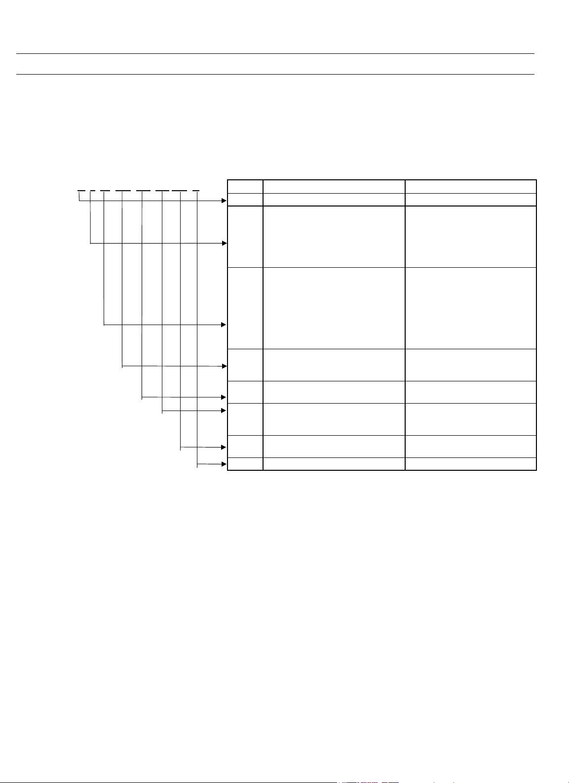
Since this Trip Unit is available in a variety of
configurations, please take a moment to compare the
catalog number of your purchased Trip Unit with the
catalog number key below.
Example
K 3 32 LSI GD Z1 PM R Code Description Function
K WavePro Breaker Family
8
800 A
1
1600 A
2
2000 A
3
3200 A
4
4000 A
5
5000 A
01
150 A
04
400 A
08
800 A
16
1600 A
20
2000 A
32
3200 A
40
4000 A
50
5000 A
L
Long-time
S
Short-time
I
Instantaneous
GGDGround Fault
Ground Fault (user defeatable) Ground fault protection
Z1
GF Zone-Selective Interlock
Z2
GF & ST Zone-Selective Interlock
X
Switchable Inst, ST, and GF
PMProtective Relays & Comm
Metering & Comm
R Replacement unit Ordered as Replacement
Frame Size
Installed CT
Overcurrent Protection
Optional protection
Optional features
Example – a Trip Unit with catalog number K332LSIGDZ1PMR has the following features:
• WavePro circuit breaker
• 3200 A frame
• 3200 A installed CT
• Long-time, short-time, and instantaneous overcurrent protection
• Defeatable ground-fault protection
• Ground-fault zone-selective interlock
• Protective relays, metering, and communication
• Trip Unit was ordered as a replacement
Page 3

WARNINGS
CAUTIONS
NOTES
DEH–178
WARNINGS, CAUTIONS, AND NOTES
AS USED IN THIS PUBLICATION
Warning notices are used in this publication to emphasize that hazardous voltages, currents, or
other conditions that could cause personal injury exist in this equipment or may be associated with
its use.
Warning notices are also used for situations in which inattention or lack of equipment knowledge
could cause either personal injury or damage to equipment.
Caution notices are used for situations in which equipment might be damaged if care is not taken.
Notes call attention to information that is especially significant to understanding and operating the
equipment.
This document is based on information available at the time of its publication. While efforts have
been made to ensure accuracy, the information contained herein does not cover all details or
variations in hardware and software, nor does it provide for every possible contingency in
connection with installation, operation, and maintenance. Features may be described herein that
are not present in all hardware and software systems. GE Electrical Distribution & Control assumes
no obligation of notice to holders of this document with respect to changes subsequently made.
GE Electrical Distribution & Control makes no representation or warranty, expressed, implied, or
statutory, with respect to, and assumes no responsibility for the accuracy, completeness, sufficiency,
or usefulness of the information contained herein. No warrantees of merchantability or fitness for
purpose shall apply.
The following are trademarks of GE Company:
MicroVersaTrip Plus™, MicroVersaTrip PM™, WavePro™, Power+™, POWER LEADER™
©Copyright 1997 GE Company
All Rights Reserved
i
Page 4

MicroVersaTrip Plus™ and MicroVersaTrip PM™ Trip Units
Table of Contents
Chapter 1. Introduction
1- Product Description ..................................................................................................................................1
1-2 Trip Unit Functions ................................................................................................................................1
1-3 Trip Unit Catalog Numbers ....................................................................................................................2
1-4 Rating Plugs.............................................................................................................................................3
1-5 Equipment Interfaces..............................................................................................................................4
MicroVersaTrip Plus Trip Units ..................................................................................................... 4
Neutral Current Sensors..................................................................................................................4
MicroVersaTrip PM Trip Units.......................................................................................................4
POWER LEADER™ Communication Network..............................................................................4
Voltage Inputs..................................................................................................................................4
Power Requirements........................................................................................................................ 4
1-6 Trip Unit Information ............................................................................................................................5
Trip Unit Label Information ..........................................................................................................5
Function Keys...................................................................................................................................5
Battery Function..............................................................................................................................5
Liquid Crystal Display......................................................................................................................6
1-7 MicroVersaTrip Plus and MicroVersaTrip PM Accuracies....................................................................6
Chapter 2. Setup Mode
2-1 Overview................................................................................................................................................... 8
2-2 Operating Modes.....................................................................................................................................8
2-3 Setup Mode Operation............................................................................................................................ 8
Long-Time Pickup......................................................................................................................... 14
Long-Time Delay...........................................................................................................................14
Short-Time Pickup......................................................................................................................... 14
Short-Time Delay........................................................................................................................... 15
Instantaneous Pickup....................................................................................................................15
Ground-Fault Pickup.....................................................................................................................16
Ground-Fault Delay....................................................................................................................... 16
Voltage-Unbalance Relay Pickup.................................................................................................. 17
Voltage-Unbalance Relay Delay .................................................................................................... 17
Current-Unbalance Relay Pickup.................................................................................................. 17
Current-Unbalance Relay Delay.................................................................................................... 17
Undervoltage Relay Pickup...........................................................................................................18
Undervoltage Relay Zero-Volt Trip Enable.................................................................................. 18
Undervoltage Relay Delay............................................................................................................. 18
Overvoltage Relay Pickup.............................................................................................................. 18
Overvoltage Relay Delay................................................................................................................ 18
Power-Reversal Relay Pickup......................................................................................................... 18
Power Direction Setup................................................................................................................... 19
Power-Reversal Relay Delay........................................................................................................... 19
Rating Plug Current Setting.......................................................................................................... 19
Potential Transformer Primary Voltage ....................................................................................... 19
ii
Page 5

Potential Transformer Connection...............................................................................................20
Power Demand Intervals ...............................................................................................................20
Communication Address...............................................................................................................20
Chapter 3. Metering Mode
3-1 Overview.................................................................................................................................................21
3-2 Metering Mode Operation ....................................................................................................................21
Current...........................................................................................................................................23
Voltage ...........................................................................................................................................23
Energy............................................................................................................................................23
Total Real Power............................................................................................................................23
Total Aggregate Power .................................................................................................................. 23
Power Demand...............................................................................................................................24
Peak Power Demand......................................................................................................................24
Frequency.......................................................................................................................................24
Chapter 4. Status Mode
4-1 Overview.................................................................................................................................................25
Trip Information...........................................................................................................................25
Trip Operations Counters............................................................................................................. 25
4-2 Status Mode Operation..........................................................................................................................25
Normal Status Display....................................................................................................................25
Long-Time Overcurrent Pickup Display.......................................................................................25
Trip Target and Fault Displays.....................................................................................................25
Long-Time Overcurrent Fault Display.......................................................................................... 26
Short-Time Overcurrent Fault Display..........................................................................................26
Instantaneous Fault Display ..........................................................................................................26
Ground-Fault Display.....................................................................................................................26
Protective-Relay Fault Display........................................................................................................26
Clearing the Trip Information...................................................................................................... 26
Trip Operations Counter Display .................................................................................................27
Clearing the Trip Operations Counters........................................................................................27
MicroVersaTrip Plus™ and MicroVersaTrip PM™ Trip Units
Table of Contents
Chapter 5. Maintenance and Trouble-Shooting
5-1 Trip Unit Removal and Replacement...................................................................................................28
5-2 Rating Plug Removal and Replacement...............................................................................................28
5-3 Trouble-Shooting Guide........................................................................................................................30
iii
Page 6

MicroVersaTrip Plus™ and MicroVersaTrip PM™ Trip Units
List of Figures
1. Front view of the MicroVersaTrip PM Trip Unit. .................................................................................................. 1
2. Labels on front of Trip Unit....................................................................................................................................5
3. Function key placement on face of Trip Unit........................................................................................................ 5
4. Liquid crystal display segments............................................................................................................................... 7
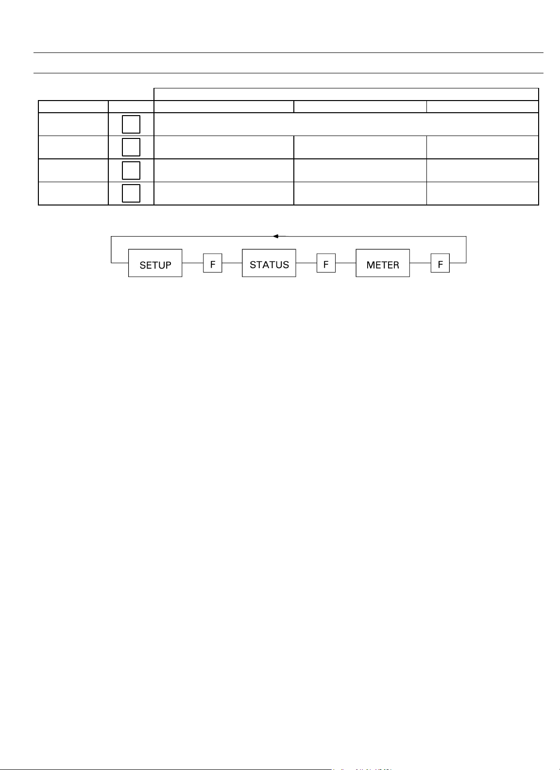
5. Operation of FUNCTION key, showing progression among Trip Unit operating modes.......................................9
6. Trip Unit setup mode programming function flow.............................................................................................10
7. Trip Unit display for long-time pickup................................................................................................................. 14
8. Time-current curve illustrating long-time pickup................................................................................................ 14
9. Trip Unit display for long-time delay. ..................................................................................................................14
10. Time-current curve illustrating long-time delay................................................................................................... 14
11. Trip Unit display for short-time pickup coupled with long-time pickup............................................................. 14
12. Time-current curve illustrating short-time pickup...............................................................................................15
13. Trip Unit display for short-time delay. ................................................................................................................. 15
14. Time-current curve for short-time delay with I
15. Time-current curve for short-time delay with I
16. Trip Unit display for instantaneous pickup. ........................................................................................................15
17. Instantaneous overcurrent protection set point...................................................................................................16
18. Trip Unit display for ground-fault pickup............................................................................................................16
19. Time-current curve for ground-fault pickup........................................................................................................ 16
20. Trip Unit display for ground-fault delay, showing I
21. Time-current curve for ground-fault delay with I
22. Time-current curve for ground-fault delay with I
23. Trip Unit display for voltage-unbalance relay pickup.......................................................................................... 17
24. Trip Unit display for voltage-unbalance relay delay.............................................................................................17
25. Trip Unit display for current-unbalance relay pickup......................................................................................... 17
26. Trip Unit display for current-unbalance relay delay............................................................................................ 18
27. TripUnit display for undervoltage relay pickup................................................................................................... 18
28. Trip Unit display for undervoltage relay zero-volt trip disabled..........................................................................18
29. Trip Unit display for undervoltage relay zero-volt trip enabled........................................................................... 18
30. Trip Unit display for undervoltage relay delay..................................................................................................... 18
31. Trip Unit display for overvoltage relay pickup..................................................................................................... 18
32. Trip Unit display for overvoltage relay delay........................................................................................................ 18
33. Trip Unit display for power-reversal relay pickup................................................................................................19
34. Trip Unit display for power direction setup, showing line to load......................................................................19
35. Trip Unit display for power-reversal relay delay................................................................................................... 19
36. Trip Unit display for rating plug current set point.............................................................................................. 19
37. Trip Unit display for potential transformer primary voltage set point................................................................19
38. Trip Unit display for potential transformer connection choice..........................................................................20
39. Trip Unit display for power demand interval.......................................................................................................20
40. Trip Unit display for setting communication address......................................................................................... 20
2
T OUT..........................................................................................15
2
T IN. ............................................................................................ 15
2
T OUT.................................................................................. 16
2
T OUT...................................................................................... 17
2
T IN. ........................................................................................ 17
iv
Page 7

MicroVersaTrip Plus™ and MicroVersaTrip PM™ Trip Units
List of Figures
41. Trip Unit metering mode function flow...............................................................................................................21
42. Trip Unit display for current metering.................................................................................................................23
43. Trip Unit display for line-to-neutral voltages........................................................................................................ 23
44. Trip Unit display for line-to-line voltages. ............................................................................................................23
45. Trip Unit display for aggregate energy.................................................................................................................23
46. Trip Unit display for aggregate real power...........................................................................................................23
47. Trip Unit display for aggregate apparent power..................................................................................................23
48. Trip Unit display for power demand....................................................................................................................24
49. Trip Unit display for frequency. ...........................................................................................................................24
50. Trip Unit display for normal status.......................................................................................................................25
51. Trip Unit status display for long-time overcurrent pickup...................................................................................25
52. Typical fault display following a breaker trip.......................................................................................................25
53. Trip Unit Status display for long-time overcurrent trip........................................................................................26
54. Trip Unit status display for short-time overcurrent trip....................................................................................... 26
55. Trip Unit status display for instantaneous overcurrent trip.................................................................................26
56. Trip Unit status display for ground-fault trip.......................................................................................................26
57. Trip Unit status display for protective-relay trip...................................................................................................26
58. Trip Unit status display for long-time overcurrent trip counter. ......................................................................... 27
59. Removing the interchangeable rating plug..........................................................................................................29
v
Page 8

MicroVersaTrip Plus™ and MicroVersaTrip® PM Trip Units
List of Tables
1. Breaker frame size maximum CT referred to by second character of Trip Unit catalog number....................... 2
2. Installed breaker CT size referred to by third and fourth characters of Trip Unit catalog number.................... 2
3. Trip Unit catalog number suffixes for optional functions..................................................................................... 2
4. MicroVersaTrip PM Trip Unit suffixes for communication, metering, and relaying. .........................................3
5. Rating plug catalog numbers..................................................................................................................................3
6. Protective relay and metering accuracies and resolutions.....................................................................................6
7. Abbreviations used in setup procedure descriptions.............................................................................................. 8
8. Comparison of Trip Unit settings abbreviations....................................................................................................8
9. Actions of function keys in Trip Unit operating modes......................................................................................... 9
10. Lower-limit delays for long-time delay bands. ......................................................................................................14
11. Lower-limit delays for I
12. Instantaneous pickup settings for various frame sizes with and without the short-time function......................16
13. Ground-fault pickup settings, as a function of sensor rating. .............................................................................. 16
14. Lower-limit delays for ground-fault delay bands. ................................................................................................. 17
15. Trip Unit rating plug options............................................................................................................................... 19
16. Trip Unit display targets for protective relays. .....................................................................................................26
2
T OUT short-time delay bands......................................................................................... 15
vi
Page 9
MicroVersaTrip Plus™ and MicroVersaTrip PM™ Trip Units
Chapter 1. Introduction
1-1 Product Desription
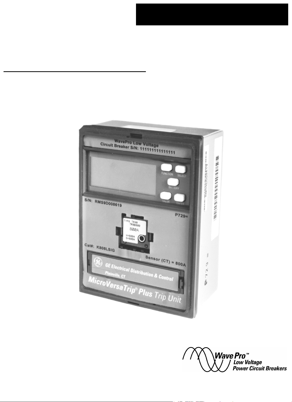
The MicroVersaTrip Plus™ and MicroVersaTrip PM™
Trip Units described in this publication are used on
WavePro™ low-voltage power circuit breakers. A front view
of the MicroVersaTrip Plus Trip Unit is shown in Figure 1.
The Trip Unit has a 50-pin rear connector that provides
the Trip Unit’s main connections to the circuit breaker
frame and to the equipment control signals.
There is a recessed connector in the front panel to accept
interchangeable current rating plugs.
CAUTION: Do not attempt to operate the breaker without
its assigned Trip Unit. Installation of an incorrect Trip
Unit may result in unsafe operation of the breaker.
ATTENTION: Ne pas utiliser le disjoncteur sans son
déclencheur. Une mauvaise installation du déclencheur
peut être dangereuse.
CAUTION: Removal of the rating plug while the breaker
is carrying current reduces the breaker’s current-carrying
capacity to approximately 25% of the current sensor rating. This may result in undesired tripping.
ATTENTION: Si le calibreur est retiré alors que le
disjoncteur est sous tension, le déclencheur se régle
automatiquement à approximativement 25% du calibre
du transformateur de courant. Ceci peut entrainer un
déclenchement indésirable.
NOTE: Trip Units as received may have settings that are
undesirable for the specific application. Ensure that settings are appropriately adjusted before energizing.
Figure 1. Front view of a MicroVersaTrip Plus Trip Unit.
CAUTION: Removal of a Trip Unit from its breaker must
be performed with the breaker in the OPEN or TRIPPED
position. Draw-out breakers should be racked out first.
ATTENTION: Pour retirer déclencheur, le disjoncteur
doit être en position ouverte ou déclenchée. Les
disjoncteurs débrochables doivent ètre en position
débrochée.
NOTE: Les disjoncteurs sont livrés avec des réglages
standards qui peuvent être inadéquates pour certaines
applications. Vérifier ces réglages avant de mettre le
disjoncteur sous tension.
1-2 Trip Unit Functions
MicroVersaTrip Plus and MicroVersaTrip PM Trip Units
have specific standard and optional functions. All Trip
Units share a series of interchangeable rating plugs. The
standard functions for both types of Trip Unit are as follows:
• Protection
– Long-time protection
– Instantaneous protection
• Status
– Trip target (trip type)
– Trip information (magnitude and phase)
– Trip operations counters
• Metering display
– Phase current (selectable among phases)
The optional functions available on both types of Trip
Unit are as follows:
• Short-time protection, with or without I2T
• Ground-fault protection, with or without I2T
1
Page 10
MicroVersaTrip Plus™ and MicroVersaTrip PM™ Trip Units
Chapter 1. Introduction
• Defeatable ground fault, with or without I2T
• Zone-selective interlock, with ground fault only or
with both ground fault and short-time protection
• Switchable short time and instantaneous with ground
fault
Additional optional functions available only with
MicroVersaTrip PM Trip Units are as follows:
• Available configurations
– Communication and metering
– Communication, metering, and protective
relaying
• Remote communication with POWER LEADER™
communications network (commnet)
• Metering functions
– Voltage (V)
– Energy (kWh/MWh/GWh)
– Total real power (kW/MW)
– Total apparent power (kVA/MVA)
– Demand power (kW/MW)
– Peak demand power (kW/MW)
– Frequency (Hz)
• Protective relaying
– Undervoltage
– Overvoltage
– Voltage unbalance
– Current unbalance
– Power reversal
NOTE: MicroVersaTrip PM style Trip Units require
external +24 Vdc control power.
NOTE: Le déclencheur de type MicroVersaTrip PM
necessite l’utilisation d’une alimentation extérieure 24
Vcc.
1-3 Trip Unit Catalog Numbers
A simple catalog-numbering system defines all of the standard and optional Trip Unit functions for each of the two
series of Trip Units. K332LSIGDZ1R is an example of a
valid catalog number.
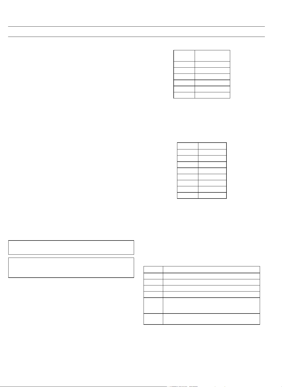
The first character of the catalog number, K, defines the
Trip Unit as configured for a WavePro circuit breaker.
Table 1. Breaker frame size referred to by the second character of the
The third and fourth characters of the catalog number
indicate the CT that is actually installed in the breaker, as
listed in Table 2.
Table 2. Installed breaker CT size referred to by third and fourth
The fifth character of the catalog number is the letter L,
which indicates that all Trip Units come with long-time
overcurrent protection. Additional letters are appended to
the catalog number to indicate installed protective functions, as in Table 3. These suffixes are valid for both
MicroVersaTrip Plus and MicroVersaTrip PM Trip Units.
They are appended from left to right in the order given.
Suffix Protective Function
S Short-time overcurrent protection
I Instantaneous overcurrent protection
G Ground fault
GD Defeatable ground fault (not UL listed)
Z1 orZ2Zone-selective interlock:
X Switchable instantaneous/short time and ground
Table 3. Trip Unit catalog number suffixes for optional functions.
Code
Trip Unit catalog number.
characters of Trip Unit catalog number.
Z1 – ground fault only
Z2 -– ground fault and short time
fault (not UL listed)
Breaker
Frame Size
8 800 A
1 1600 A
2 2000 A
3 3200 A
4 4000 A
5 5000 A
Code CT Size
01 150 A
04 400 A
08 800 A
16 1600 A
20 2000 A
32 3200 A
40 4000 A
50 5000 A
The second character of the catalog number indicates the
breaker frame size, as listed in Table 1.
MicroVersaTrip PM catalog numbers contain an additional one- or two-letter suffix to indicate the communication, metering, and relaying functions installed, as shown
2
Page 11

MicroVersaTrip Plus™ and MicroVersaTrip PM™ Trip Units
Chapter 1. Introduction
in Table 4. MicroVersaTrip Plus catalog numbers do not
have this final suffix.
Suffix Function
(none) MicroVersaTrip Plus Trip Unit
PM Metering, relaying, and communication
M Metering and communication
Table 4. MicroVersaTrip PM Trip Unit suffixes for communication,
metering, and relaying.
Finally, if the Trip Unit is ordered as a replacement, an
“R” suffix is appended to the catalog number.
For example, a Trip Unit with catalog number
K332LSIGDZ1PMR has the following functions:
K -- Trip Unit for Wave Pro circuit breaker
3 – Frame size of 3200 A
32 – breaker current sensor (CT) of 3200 A
L -- long-time overcurrent protection
Catalog
Number
TR1B60 60 TR20B750 750
TR1B80 80 TR20B800 800
TR1B100 150 100 800 TR20B1000 2000 1000 2000
TR1B125 125 TR20B1200 1200
TR1B150 150 TR20B1500 1500
TR4B150 150 TR20B1600 1600
TR4B200 200 TR20B2000 2000
TR4B225 400 225 800 TR32B1200 1200
TR4B250 250 TR32B1600 3200 1600 3200
TR4B300 300 TR32B2400 2400
TR4B400 400 TR32B3200 3200
TR8B300 300 TR40B1600 1600
TR8B400 400 TR40B2000 2000
TR8B450 450 TR40B2500 4000 2500 4000
TR8B500 800 500 800 TR40B3000 3000
TR8B600 600 1600 TR40B3600 3600
TR8B700 700 TR40B4000 4000
TR8B800 800 TR50B3200 3200
TR16B600 600 TR50B4000 5000 4000 5000
TR16B800 800 1600 TR50B5000 5000
TR16B1000 1600 1000
TR16B1100 1100
TR16B1200 1200
TR16B1600 1600
Sensor
Rating,
Amps
Plug
Rating
Breaker
Frame Size,
Amps
S -- short-time overcurrent protection
I -- adjustable instantaneous protection
GD -- defeatable ground-fault protection
Z1 – ground-fault zone-selective interlock
PM -- MicroVersaTrip PM with relaying, metering, and
communication
R – Replacement Trip Unit
1-4 Rating Plugs
Interchangeable rating plugs are used to establish or
change the current rating of the breaker. Rating plugs for
MicroVersaTrip Plus or MicroVersaTrip PM Trip Units in
WavePro breakers are interchangeable within the same
sensor rating. A built-in rejection feature prevents the
insertion of a rating plug with an incorrect sensor rating
into a Trip Unit.
Rating plug catalog numbers are listed in Table 5.
Catalog
Number
Sensor
Rating,
Amps
Plug
Rating
Breaker
Frame Size,
Amps
Table 5. Rating plug catalog numbers.
3
Page 12

MicroVersaTrip Plus™ and MicroVersaTrip PM™ Trip Units
Chapter 1. Introduction
1-5 Equipment Interfaces
MicroVersaTrip Plus Trip Units
MicroVersaTrip Plus Trip Units do not usually require
connections within the equipment, since all wiring is contained within the circuit breaker. The only two connections are for optional zone-selective interlock (Z1 and Z2)
and the neutral sensor. Connections are made through
the breaker’s secondary disconnect A.
Zone-selective interlocking coordinates breakers, so that
the downstream breaker is allowed the first opportunity to
clear a disturbance. The two types of available zone-selective interlocking are Z1, which reacts only to ground faults,
and Z2, which reacts to both ground faults and short-time
overcurrent pickups. Separately mounted zone-selective
interlock modules are required between upstream and
downstream breakers.
Neutral Current Sensors
CAUTION: Neutral current sensors are required for
single-phase, three-wire and three-phase, four-wire systems. When the Trip Unit is connected to a three-phase,
three-wire system, the neutral sensor terminals of the
breaker are left open. Do not short any neutral current
sensor terminals in a three-phase, three-wire system, as
this could result in damage to, or malfunction of, the
electrical system.
ATTENTION: Un transformateur de courant de neutre est
nécessaire pour les réseaux 3 phases + neutre. Si le neutre
n’est pas distribué, les bornes de neutre du déclencheur
doivent être laissées ouvertes. Ne pas les court-circuiter
(ceci peut endommager le déclencheur et entrainer un
mauvais fonctionnement du système électrique.
MicroVersaTrip PM Trip Units
In addition to the inputs received by MicroVersaTrip Plus
Trip Units, MicroVersaTrip PM Trip Units also receive
inputs from external voltage conditioners, a +24 Vdc auxiliary power supply, and communication connections.
External +24 Vdc auxiliary power is required for operation.
POWER LEADER™ Communication Network
MicroVersaTrip PM Trip Units may be integrated into a
Power Management Control System through the POWER
LEADER™ Modbus Concentrator, which collects data
from a MicroVersaTrip PM Trip Unit (a commnet device)
and communicates across the RS485 network to a remote
PC. Also, MicroVersaTrip PM Trip Units can be wired to a
POWER LEADER Modbus Monitor through a Modbus
Concentrator. The Modbus Monitor, which is mounted
either in the equipment or independently, provides a central station for viewing metering and status information
collected from multiple remote power management
devices.
Commnet connections are made directly to wiring terminations on breaker frames. All commnet connections to
the Trip Units are made through the 50-pin plug on the
Trip Unit, which mates with a receptacle on the breaker
frame. These additional connections are made to the
equipment through the secondary disconnects of the
breaker.
Voltage Inputs
Voltage inputs are sensed by conventional instrument
potential transformers(PTs). PTs have 120 Vac secondaries and must always be used in groups of three; no
open-delta connections are permitted. PT primaries are
connected either line-to-line or line-to-neutral, as required.
PTs may be used for other monitoring functions, subject to
reasonable burden limitations. Note that PTs must be
connected in a specific sequence to ensure proper phase
relations and power-flow sensing.
Each PT output feeds an individual voltage conditioner
that scales the nominal voltage to approximately 1.76 Vac
for use by the Trip Unit.
Power Requirements
A small amount of power is necessary to energize the liquid
crystal display (LCD) during setup, for viewing breaker
status, and for metering displays. MicroVersaTrip PM Trip
Units require external +24 Vdc auxiliary power for proper
operation. The four sources of such power are the
following:
• Flow of current -- Breaker current sensors provide sufficient power to energize the LCD when at least 20% of
the sensor’s ampere rating is flowing.
• +24 Vdc Auxilliary Power – Breakers with MicroVersaTrip PM Trip Units are supplied with external +24
Vdc power that, whenever present, energizes the
LCD.
• Internal Battery Power – The Trip Unit has an internal
battery that powers the unit temporarily when the
BATTERY key on the display is pressed. Battery power
automatically turns off 30 seconds after the last keypad press. The battery power supply is disabled when
any current is sensed through the current sensors.
• MicroVersaTrip Portable Power Pack -- The
MicroVersaTrip Portable Power Pack contains a dc
4
Page 13

MicroVersaTrip Plus™ and MicroVersaTrip PM™ Trip Units
Chapter 1. Introduction
power source and a cable. The LCD is energized
when the cable is plugged into the rating plug test
receptacle.
1-6 Trip Unit Information
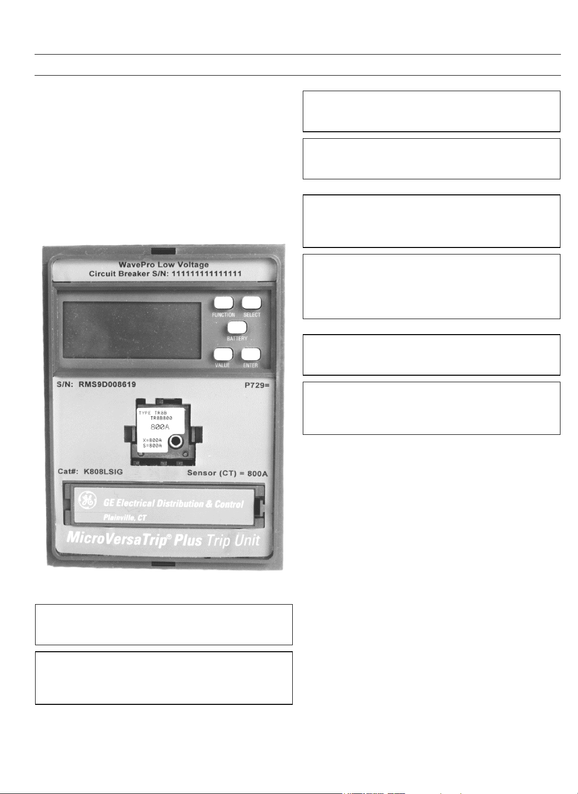
Trip Unit Label Information
Following are descriptions of the various label information
on the front of the Trip Unit, as illustrated in Figure 2.
• Extreme top -- circuit breaker series and serial number
of the breaker, unless it is a replacement unit.
• Upper-left center – Trip Unit serial number, such as
RMS9D008587.
• Upper-right center -- Trip Unit date of manufacture
code, such as P729=.
• Lower-left center -- catalog number of the Trip Unit,
such as K440LSGPM.
• Lower-right center-- sensor rating of the Trip Unit, such
as SENSOR (CT) = 4000A.
• Below battery cover -- indicates whether the unit is
MicroVersaTrip Plus or MicroVersaTrip PM.
Function Keys
The Trip Unit has four programming keys and a battery
enable key. These are marked FUNCTION, SELECT, VALUE,
ENTER, and BATTERY, as illustrated in Figure 3. All setup,
status, and metering functions and displays are accessed
through these keys. As each set point is entered, it is stored
in the Trip Unit’s nonvolatile memory, so subsequent loss
of power does not result in loss or change of any settings.
FUNCTION SELECT
BATTERY
VALUE ENTER
Figure 3. Function key placement on face of Trip Unit.
The functions of the five keys are
• FUNCTION -- selects the mode of display.
• SELECT -- chooses the next item for display.
• VALUE -- selects the phase-to-phase display or allows
changing of set points.
• ENTER -- stores set points.
• BATTERY -- powers the Trip Unit from the internal
battery.
Figure 2. Label information on the front of the Trip Unit.
Chapter 2 describes the operation of these keys in detail.
Battery Function
Pressing the BATTERY key on the face of the Trip Unit
powers the unit from its internal battery. Battery power is
maintained for 30 seconds after the last key is pressed.
This self-powered mode allows setting up the Trip Unit or
viewing trip targets when the breaker is de-energized and
external control power is unavailable. All normal setup,
meter, and status functions can be performed with battery
power.
The battery is intended to power the Trip Unit when it is
otherwise unpowered. At low line currents (less than 20%
of the sensor rating) the Trip Unit display is not active.
Pressing the BATTERY key under these conditions will not
power the Trip Unit.
Note that at temperatures above 40° C, the BATTERY key
may have to be held down for up to 5 seconds for the Trip
Unit to be powered.
5
Page 14

MicroVersaTrip Plus™ and MicroVersaTrip PM™ Trip Units
Chapter 1. Introduction
Batteries
The Trip Unit uses a lithium manganese dioxide battery
with a typical life of two years in a normally energized
breaker. Typical usage could include one half-hour of use
for first-time cold setup, 10 Trip Unit status checks per year
on a de-energized breaker, and one or two configuration
changes per year.
The battery is not required for proper operation or protection of the breaker. It is not needed nor used to store setpoints, configurations, or trip target information. It
provides a source of power to display setpoints and trip
information only if no other source of power is available.
Battery Replacement
Replace the battery if it does not power up the Trip Unit or
if the low-battery symbol appears in the display when the
BATTERY key is pressed. Lift the right-side tab of the
battery cover on the front of the Trip Unit to expose the
3.0 V lithium magnesium dioxide cell. A suitable replacement is the Duracell DL123A, which is available from
industrial distributors.
WARNING: Replace the battery with Duracell DL123A
only. Use of a different battery may present risk of fire,
explosion, or damage to equipment. Observe proper battery polarity when installing in the Trip Unit battery
compartment.
ATTENTION: Remplacer la batterie avec uniquement des
Duracell DL123A. L’utilisation d’autres batteries peut
présenter un risque de feu, d’explosion ou
d’endommagement du matériel. Respecter la polarité de
la batterie en l’installant dans son logement.
WARNING: The battery may explode if mistreated. Do
not recharge, disassemble, or dispose of in fire. Keep the
battery away from children and dispose of the used battery promptly.
Liquid Crystal Display
Figure 4 illustrates the LCD with all segments illuminated.
The various segments are energized in response to conditions sensed by the Trip Unit.
1-7 MicroVersaTrip Plus and
MicroVersaTrip PM Accuracies
The accuracy data in Table 6 represent the average
expected performance of MicroVersaTrip Plus and
MicroVersaTrip PM Trip Units. These data are valid for
setup, metering, and status mode displays. They include
the effects of Trip Unit ambient-temperature variation
from 0° C to 70° C.
All percentages are based on full-scale values. Full-scale
current is xIn, the rating of the breaker’s rating plug. Fullscale voltage is the potential transformer primary voltage
rating. These data do not include the accuracy rating of
any measuring instrument.
For characteristics and accuracies of overcurrent protection, refer to DES–001 for long- time delay, short-time
delay, and instantaneous time-current curves and DES–
002 for ground-fault time-current curves.
Value
Current (A, kA) ± 2% ± 0.5 digit
Voltage (V) ± 1.5% ± 0.5 digit
Energy (kWh, MWh, GWh) ± 3.5% ± 0.5 digit
Real power (kW, MW) ± 3.5% ± 0.5 digit
Total power (kVA, MVA) ± 3.5% ± 0.5 digit
Frequency (Hz) ± 1 Hz ± 1 Hz
Time delay (sec) ± 1 sec ± 1 sec
Table 6. Protective relay and metering accuracies and resolutions.
Full-Scale
Accuracy Resolution
ATTENTION: La batterie peut exploser en cas de
mauvaise utilisation. Ne pas la recharger, l’ouvrir ou la
jeter dans un feu. Doit être garder hors de portée des
enfants. Une fois usée, la batterie doit être jeté
rapidement.
6
Page 15

MicroVersaTrip Plus™ and PM Trip Units
Figure 4. Liquid crystal display segments.
Chapter 1. Introduction
7
Page 16

MicroVersaTrip Plus™ and MicroVersaTrip PM™ Trip Units
Chapter 2. Setup Mode
2-1 Overview
This chapter describes the operation of the four programming keys, set point and time-delay adjustments, and
their accuracies. The setup procedures should only be
repeated if the Trip Unit or the protection characteristics
are changed, requiring different set points and time
delays.
These procedures apply to MicroVersaTrip Plus and
MicroVersaTrip PM Trip Units. Setup programming must
be performed with the rating plug installed.
For Trip Units set up through the Power Management
Control System, refer to instructions published for that
system.
Table 7 contains a list of abbreviations used throughout
the description of the setup procedures.
Abbr. Description
xIn Rating plug ampere rating.
xCT Current sensor ampere rating.
xLT Long–time (LT) current setting in amperes. Multiply LT
WavePro circuit breakers are available with Power+™ as
well as MicroVersaTrip Plus and MicroVersaTrip PM Trip
Units. There are two different sets of abbreviations used to
describe the same TripUnit settings in the documentation
and on the Trip Unit labels. These abbreviations are listed
in Table 8.
set point by rating plug amperes.
xLT = (LT setpoint multiplier) x (xIn)
FUNCTION key on face of Trip Unit.
F
SELECT key on face of Trip Unit.
S
VALUE key on face of Trip Unit.
V
ENTER key on face of Trip Unit.
E
Table 7. Abbreviations used in setup procedure descriptions.
Trip Unit Setting Abbreviations
Rating Plug rating, A xIn X
Current Sensor rating, A xCT S
Current setting, A xLT C
2-2 Operating Modes
MicroVersaTrip Plus and MicroVersaTrip PM Trip Units
have three operating modes: Setup, Metering, and Status.
The effects of each of the four programming keys in each
mode are listed in Table 9.
All the programming keys, except for ENTER, automatically
step the Trip Unit display to the next available option each
time the key is pressed. Continued pressing of a key
eventually loops the display back to the initial option for
that function. This is illustrated in Figure 5 for the
FUNCTION key, which shows that repeatedly pressing this
key cycles the mode among Status, Metering, and Setup.
Pressing the ENTER key more than once has no effect.
In Setup mode, depressing the VALUE key for about 5 seconds activates a fast scan that rapidly displays each of the
available set points or time delays for some of the trip
characteristics.
2-3 Setup Mode Operation
The following instructions describe setup procedures for
all available Trip Unit functions. These are illustrated in
Figure 6. All Trip Units provide long-time overcurrent
protection, long-time delay, and some form of short-circuit
protection. All other functions are optional.
If a specific set of Trip Unit functions, such as relaying or
short-time overcurrent protection, has not been ordered,
that function will not appear on the Trip Unit display.
Ignore setup mode instructions for such functions.
The Trip Unit must be provided with auxiliary power during setup. This can come from internal battery power,
from a MicroVersaTrip Portable Power Pack, or from an
external +24 Vdc power supply.
To begin the process, press the FUNCTION key until SETUP
appears in the upper-right corner of the Trip Unit display.
Setup mode always begins with long-time pickup. After a
choice has been made for this and each subsequent trip
function, press SELECT to advance to the next function.
Table 8. Comparison of Trip Unit settings abbreviations.
8
Page 17
MicroVersaTrip Plus™ and MicroVersaTrip PM™ Trip Units
Chapter 2. Setup Mode
Trip Unit Operating Mode
Key Symbol Setup Metering Status
FUNCTION
SELECT
VALUE
ENTER
F
Select next programming display Select next metering display Select next status display
S
Display next set point or time-delay
V
value
Store set point or time-delay value
E
into memory
Table 9. Actions of function keys in Trip Unit operating modes.
Figure 5. Operation of FUNCTION key, showing progression among Trip Unit operating modes.
Select one of three modes: Setup, Metering, Status
Display next phase value No effect
No effect No effect
Set points are entered into memory in three steps: display,
select, and activate, as described below:
1. Press the VALUE key until the desired set point is displayed flashing on the LCD.
2. Press the ENTER key to select this set point. The displayed value stops flashing and the SETUP icon
flashes on the LCD. This indicates that the value has
been stored in memory but is not yet active. If a new
set point is displayed but not selected by pressing the
ENTER key (set point value still flashing), then the
displayed set point is not entered into memory and
the original value is maintained. Multiple set point
changes can be made in this fashion without changing the active settings. For each of these changes, the
SETUP icon continues to flash.
3. Press the FUNCTION key to activate these settings in
the Trip Unit. The SETUP icon no longer flashes,
which indicates that any selected settings are also
currently active. The FUNCTION key should always be
pressed following set point changes to ensure that the
active settings match the stored settings.
The set point change steps are summarized as follows:
• Display set point – Press the VALUE key until the
desired setting is flashing.
• Select set point – Press the ENTER key; the setting
stops flashing and the SETUP icon starts flashing.
• Activate set points – Press the FUNCTION key to activate the settings; the SETUP icon stops flashing.
Always confirm settings on the Trip Unit after making
changes by exiting and re-entering Setup mode and
rechecking each changed setting.
9
Page 18

MicroVersaTrip Plus™ and MicroVersaTrip PM™ Trip Units
Chapter 2. Setup Mode
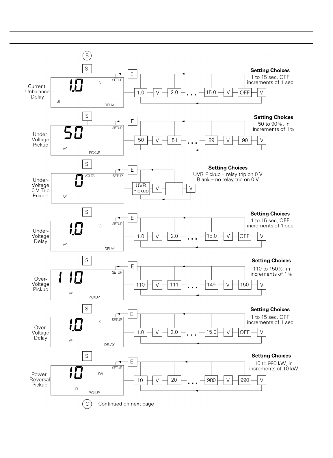
Figure 6. Trip Unit setup mode programming function flow.
10
Page 19

MicroVersaTrip Plus™ and MicroVersaTrip PM™ Trip Units
Chapter 2. Setup Mode
Figure 6. Trip Unit setup mode programming function flow (continued).
11
Page 20
MicroVersaTrip Plus™ and MicroVersaTrip PM™ Trip Units
Chapter 2. Setup Mode
Figure 6. Trip Unit setup mode programming function flow (continued).
12
Page 21

MicroVersaTrip Plus™ and MicroVersaTrip PM™ Trip Units
Chapter 2. Setup Mode
Figure 6. Trip Unit setup mode programming function flow (continued).
13
Page 22

MicroVersaTrip Plus™ and MicroVersaTrip PM™ Trip Units
Chapter 2. Setup Mode
Long-Time Pickup
The first setup-mode display is always the long-time pickup
setpoint, as illustrated in Figure 7. This set point
establishes the breaker’s nominal ampere rating, xLT, as a
fraction of the rating plug value, xIn (xLT = LT multiplier
x xIn). Press the VALUE key to scroll through the available
choices. Press ENTER to store the desired set point.
Figure 9. Trip Unit display for long-time delay.
Band Delay, sec
1 2.4
2 4.9
3 9.8
4 20
Figure 7. Trip Unit display for long-time pickup.
The choices are 0.50 to 1.10 times xIn, in steps of 0.05. The
pickup value is defined for −10% to +10% of the set point.
Figure 8 illustrates the long-time pickup settings.
Figure 8. Time-current curve illustrating long-time pickup.
Long-Time Delay
The Trip Unit display for long-time delay is illustrated in
Figure 9. This function allows normal momentary overloads without nuisance tripping. The time delays at the
lower limit of the bands at 600% of the long-time current
setting, xLT, are listed in Table 10. Figure 10 illustrates the
effect of this delay on trip time. Press the VALUE key to
cycle through the four choices of time-delay bands. Press
ENTER to store the desired value.
Table 10. Lower-limit delays for long-time delay bands.
Figure 10. Time-current curve illustrating long-time delay.
Short-Time Pickup
The short-time pickup function establishes the current at
which short-time trip is activated. Short-time pickup is
coupled with long-time pickup and the choices of pickup
settings are from 1.5 to 9.0 times the long-time setting, xLT,
in steps of 0.5 xLT. The Trip Unit display is illustrated in
Figure 11. The time-current curve for short-time pickup is
shown in Figure 12.
Figure 11. Trip Unit display for short-time pickup coupled with long-
time pickup.
14
Page 23

MicroVersaTrip Plus™ and MicroVersaTrip PM™ Trip Units
Chapter 2. Setup Mode
Figure 12. Time-current curve illustrating short-time pickup.
Short-Time Delay
The Trip Unit display for short-time delay is shown in
Figure 13. This function delays the breaker trip on a shorttime trip. The choices of time-delay bands are listed in
Table 11. The delay with I
xLT at the lower limit of the band. The delay with I
is for the lower limit of each band.
On ANSI Trip Units ordered with the user-selectable,
switchable instantaneous overcurrent and ground-fault
option, “X,” an additional value of OFF appears at the end
of the delay band settings. Choosing OFF disables shorttime protection. The short-time OFF band is interlocked
with instantaneous pickup, so that only one function can
be turned off at a time.
2
The I
T OUT function, illustrated in Figure 14, establishes
a constant time delay. I
stant slope, as shown in Figure 15.
2
T IN is for a current of 600% of
2
T IN biases the delay with a con-
2
T OUT
Figure 14. Time-current curve for short-time delay with I
Figure 15. Time-current curve for short-time delay with I
2
T OUT.
2
T IN.
Instantaneous Pickup
Instantaneous overcurrent protection, with Trip Unit display illustrated in Figure 16, causes an immediate breaker
trip when the chosen current level is reached. The pickup
value may be set in steps of 0.5 xIn from 1.5 xIn to a maximum dependent on the frame size and the presence of the
short-time function, as listed in Table 12.
Figure 13. Trip Unit display for short-time delay.
Band Time Delays, sec
1 0.10
2 0.21
3 0.35
Table 11. Lower-limit delays for I
2
T OUT short-time delay bands.
Note the difference from short-time pickup, which is based
on a multiple of xLT. The time-current characteristic is
shown in Figure 17.
Figure 16. Trip Unit display for instantaneous pickup.
15
Page 24

MicroVersaTrip Plus™ and MicroVersaTrip PM™ Trip Units
Chapter 2. Setup Mode
Sensor, A Set Points
150–2000 0.20–0.60
3200 0.20–0.37
4000 0.20–0.30
5000 0.20–0.24
Table 13. Ground-fault pickup settings, as a function of sensor rating.
Figure 17. Instantaneous overcurrent protection set point.
Frame Max. Amp
Rating
2000 1.5–10.0 xIn 1.5–15.0 xIn
3200 1.5–10.0 xIn 1.5–13.0 xIn
4000 1.5–9.0 xIn 1.5–9.0 xIn
5000 1.5–7.0 xIn 1.5–7.0 xIn
Setpoints Without
ST
Setpoints
With ST
Table 12. Instantaneous pickup settings for various frame sizes with
and without the short-time function.
On Trip Units with the user-selectable switchable instantaneous overcurrent and ground-fault option, X, an additional value of OFF appears at the end of the listing of
numerical values. Choose this setting to disable instantaneous protection. The instantaneous OFF selection is
interlocked with short-time pickup, so that only one
function can be turned off at a time.
Ground-Fault Pickup
The trip unit display for ground-fault pickup is shown in
Figure 18. This function sets the pickup current for
ground-fault protection. The available settings are listed in
Table 13 as multiples of xCT the current sensor rating, in
steps of 0.01 xCT. The maximum value is limited to 1200
A. Figure 19 illustrates the time-current curve for groundfault pickup.
Figure 19. Time-current curve for ground-fault pickup.
Ground-Fault Delay
This function sets the delay before the breaker trips when
the ground-fault pickup current has been detected. The
Trip Unit display is shown in Figure 20. The choices are
listed in Table 14. The delay for I
limit of each band. The delay for I
pickup setting at the lower limit of the band.
2
The I
T OUT function establishes a constant time delay, as
shown in Figure 21. I
2
T IN biases the delay with a constant
slope, as shown in Figure 22.
With the X or GD options (switchable or defeatable
ground fault), an OFF selection appears as an additional
time-delay set point. Selecting OFF disables ground-fault
protection.
2
T OUT is at the lower
2
T IN is at 200% of the
Figure 18. Trip Unit display for ground-fault pickup.
Figure 20. Trip Unit display for ground-fault delay, showing I
16
2
T out.
Page 25

MicroVersaTrip Plus™ and MicroVersaTrip PM™ Trip Units
Band Time Delay, sec
OFF Disabled
1 0.10
2 0.21
3 0.35
Table 14. Lower-limit delays for ground-fault delay bands.
Chapter 2. Setup Mode
Figure 23. Trip Unit display for voltage-unbalance relay pickup.
Voltage-Unbalance Relay Delay
This function sets the delay time before a voltage-unbalance trip occurs. The range of delays is 1 to 15 seconds, in
steps of 1 second. Choosing OFF disables voltage-unbalance protection. The Trip Unit display is shown in Figure
24.
Figure 21. Time-current curve for ground-fault delay with I
Figure 22. Time-current curve for ground-fault delay with I
2
T OUT.
2
T IN.
Voltage-Unbalance Relay Pickup
This function compares the highest or lowest phase voltage with the average of all three phases and initiates a trip
if the difference exceeds the set point. The true rms voltage is computed for each phase. The range of set points is
from 10 to 50% of the unbalance, with an increment of
1%. The Trip Unit display is shown in Figure 23.
Figure 24. Trip Unit display for voltage-unbalance relay delay.
Current-Unbalance Relay Pickup
This function compares the true RMS current in the
highest or lowest phase with the average of all three phases
and initiates a trip if the difference exceeds the set point.
The range of set points is 10 to 50% of the unbalance, with
an increment of 1%. The Trip Unit display is shown in
Figure 25.
Figure 25. Trip Unit display for current-unbalance relay pickup.
Current-Unbalance Relay Delay
This function sets the delay time before a current-unbalance trip occurs. The range of delays is 1 to 15 seconds, in
steps of 1 second. Choosing OFF disables current-unbalance protection. The Trip Unit display is shown in Figure
26.
17
Page 26

MicroVersaTrip Plus™ and MicroVersaTrip PM™ Trip Units
Chapter 2. Setup Mode
Undervoltage Relay Delay
This function sets the delay time before an undervoltage
trip occurs. The range of delays is 1 to 15 seconds, in steps
of 1 second. Choosing OFF disables undervoltage protection. The Trip Unit display is shown in Figure 30.
Figure 26. Trip Unit display for current-unbalance relay delay.
Undervoltage Relay Pickup
This function measures the true rms voltage in all phases
and initiates a trip if any phase voltage drops below the set
point. The range of set points is 50 to 90% of the nominal
voltage, with an increment of 1%. The Trip Unit display is
shown in Figure 27.
Figure 30. Trip Unit display for undervoltage relay delay.
Overvoltage Relay Pickup
This function measures the true rms voltage in all phases
and initiates a trip if any phase voltage exceeds the set
point. The range of set points is 110 to 150% of the nominal voltage, with an increment of 1%. The Trip Unit display is shown in Figure 31.
Figure 27. Trip Unit display for undervoltage relay pickup.
Undervoltage Relay Zero-Volt Trip Enable
This function determines if the relay trips when all three
phase voltages drop to zero volts. The Trip Unit display for
zero-volt trip disabled is shown in Figure 28. The Trip Unit
display for zero-volt trip enabled is shown in Figure 29.
Figure 28. Trip Unit display for undervoltage relay zero-volt trip
disabled.
Figure 31. Trip Unit display for overvoltage relay pickup.
Overvoltage Relay Delay
This function sets the delay time before an overvoltage trip
occurs. The range of delays is 1 to 15 seconds, in steps of 1
second. Choosing OFF disables overvoltage protection. The
Trip Unit display is shown in Figure 32.
Figure 32. Trip Unit display for overvoltage relay delay.
Figure 29. Trip Unit display for undervoltage relay zero-volt trip
enabled.
Power-Reversal Relay Pickup
This function measures the direction of power flow
through the breaker and initiates a trip if a sufficient
magnitude of reverse power is detected. The range of set
18
Page 27

MicroVersaTrip Plus™ and MicroVersaTrip PM™ Trip Units
Chapter 2. Setup Mode
points is 10 kW to 990 kW, in steps of 10 kW. The Trip
Unit display is shown in Figure 33.
Figure 33. Trip Unit display for power-reversal relay pickup.
Power Direction Setup
This function selects the normal power flow direction for
the breaker, either from line to load or from load to line.
Figure 34 shows the setup display for normal power flow of
line to load. This direction setup also affects the sign of the
normal power metering displays.
CAUTION: Incorrect storage of this set point will result in
incorrect metering values.
ATTENTION: Si une valeur incorrecte est enregistrée
pour ce réglage, les mesures seront fausses.
Figure 36. Trip Unit display for rating plug current set point.
Breaker
Frame
Size, A Rating Plug Options, Amps
800–2000
3200 1200, 1600, 2400, 3200
4000 1600, 2000, 2500, 3000, 3600, 4000
5000 3200, 4000, 5000
60, 80, 100, 125, 150, 200, 225, 250, 300, 400, 450,
500, 600, 700, 750, 800, 1000, 1100, 1200, 1500,
1600, 2000
Figure 34. Trip Unit display for power direction setup, showing line to
load.
Power-Reversal Relay Delay
This function sets the delay time before a power-reversal
trip occurs. The range of delays is 1 to 15 seconds, in steps
of 1 second. Choosing OFF disables power-reversal protection. The Trip Unit display is shown in Figure 35.
Figure 35. Trip Unit display for power-reversal relay delay.
Rating Plug Current Setting
The Trip Unit display for rating plug setting is shown in
Figure 36. Enter the current setting of the rating plug by
scrolling through the list with VALUE and pressing ENTER
when the correct value is reached. Table 15 lists the available rating plugs for the various Trip Units.
Table 15. Trip Unit rating plug options.
Potential Transformer Primary Voltage
Enter the primary voltage rating of the potential transformer, as illustrated in Figure 37. The range of values is
120 to 600 volts, with an increment of 1 volt.
CAUTION: Incorrect storage of this set point will result in
incorrect metering values. Even if this setting is entered
remotely, it must be entered again locally.
ATTENTION: Si une valeur incorrecte est enregistrée
pour ce réglage, les mesures seront fausses. Cette valeur
doit être enregistrée locallement même dans le cas d’une
utilisation à distance avec commnet.
Figure 37. Trip Unit display for potential transformer primary voltage
set point.
19
Page 28
MicroVersaTrip Plus™ and MicroVersaTrip PM™ Trip Units
Chapter 2. Setup Mode
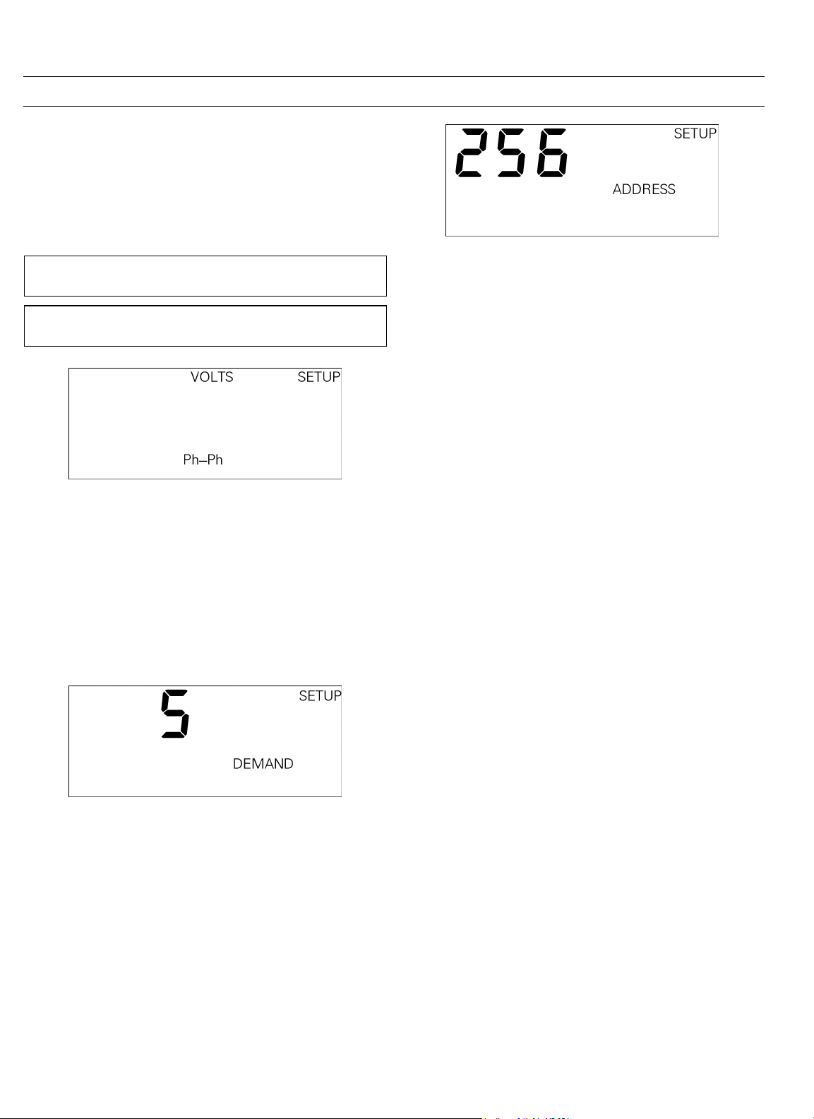
Potential Transformer Connection
Note that this step applies only to MicroVersaTrip PM Trip
Units.
Select the appropriate potential transformer connection,
either line-to-line (PH-PH) or line-to-neutral (PH-N), as
illustrated in Figure 38.
Figure 40. Trip Unit display for setting communication address.
CAUTION: Incorrect storage of this set point will result in
incorrect metering values.
ATTENTION: Si une valeur incorrecte est enregistrée
pour ce réglage, les mesures seront fausses.
Figure 38. Trip Unit display for potential transformer connection
choice.
Power Demand Intervals
This function sets the power demand interval, which can
be in the range of 5 to 60 minutes, in steps of 5 minutes.
This setpoint specifies the time interval for power demand
averaging. The Trip Unit calculates a rolling average of
breaker power over this time interval. The Trip Unit display is illustrated in Figure 39.
Figure 39. Trip Unit display for power demand interval.
Communication Address
Note that this step applies only to MicroVersaTrip PM Trip
Units connected to the Power Management Control
System.
With POWER LEADER systems, the address is assigned at
the breaker. The address options are from 256 to 999, in
steps of 1, as illustrated in Figure 40.
20
Page 29

MicroVersaTrip Plus™ and MicroVersaTrip PM™ Trip Units
Chapter 3. Metering Mode
3-1 Overview
The metering mode displays parameter values for that part
of the electrical system controlled by the breaker’s
MicroVersaTrip Plus or MicroVersaTrip PM Trip Unit.
Both currents and voltages are computed as true rms values. There is no loss of accuracy even in the presence of
high levels of harmonics. All metering displays are
updated once each second. Accuracies and resolutions are
described in Section 1-8 and Table 6.
All values except frequency are displayed to three significant figures. For example, phase currents might be displayed as 60.7 AMPS, 492 AMPS, or 1.22 KA.
The Trip Unit metering displays are appropriate to the
actual configuration ordered. All MicroVersaTrip Plus and
MicroVersaTrip PM Trip Units include current metering.
Two configurations of the MicroVersaTrip PM Trip Units
(with PM and M suffixes in their catalog numbers) have
the full complement of metering displays.
The Trip Unit must be provided with auxiliary power to
display metered values. This can come from internal battery power, from a MicroVersaTrip Portable Power pack,
from an external +24 Vdc power supply, or by energizing
the breaker to at least 20% of its sensor load.
3-2 Metering Mode Operation
Metering mode is reached by pressing FUNCTION until
METER appears in the upper-right corner of the display.
Metering mode always begins with the phase currents. The
sequence in which the metered values appear is illustrated
in Figure 41.
Figure 41. Trip Unit metering mode function flow.
21
Page 30

MicroVersaTrip Plus™ and MicroVersaTrip PM™ Trip Units
Chapter 3. Metering Mode
Figure 41. Trip Unit metering mode function flow (continued).
22
Page 31

MicroVersaTrip Plus™ and MicroVersaTrip PM™ Trip Units
Chapter 3. Metering Mode
Current
The initial metering display is phase 1 line current, as
illustrated in Figure 42. Press VALUE to cycle among the
three phases. Current is displayed from 0 to 999 amperes
and from 1.00 to a maximum of 999 kA. For current values
less than 5% of the current sensor rating, the displayed
value is zero.
Figure 42. Trip Unit display for current metering.
Voltage
The voltage displayed by this function depends on how the
Trip Unit was configured during Setup. If the breaker was
configured with phase-to-neutral connections, the display
shows individual phase voltages, as in Figure 43. If the
breaker was configured with phase-to-phase connections,
the display shows voltages between the phases, as in Figure
44. Press VALUE to cycle through the three phase voltages.
switches back to 0 kWh. The largest negative energy value
displayed is −99 GWh.
Accumulated energy is stored in nonvolatile memory. The
value in the display can be reset through the Trip Unit
keypad. To reset the energy value, hold down the VALUE
key and press the SELECT key. The displayed energy value
will reset to zero.
Figure 45. Trip Unit display for aggregate energy.
Total Real Power
The value displayed for total real power, illustrated in Figure 46, represents the aggregate real power in watts flowing through all three phases. The value is displayed from 0
to 999 kW, then automatically switches units to display 1.00
to 999 MW.
Figure 43. Trip Unit display for line-to-neutral voltages.
Figure 44. Trip Unit display for line-to-line voltages.
Energy
This display, illustrated in Figure 45, shows the aggregate
energy flow through the breaker. The value is displayed
from 0 to 999 kWh, then automatically switches units to
display 1.00 to 999 MWh, and then again to display 1.00 to
999 GWh. When 999 GWh is exceeded, the display
Figure 46. Trip Unit display for aggregate real power.
Total Apparent Power
The value displayed for total apparent power, as illustrated
in Figure 47, represents the aggregate total apparent
power in volt-amperes flowing through all three phases.
The value is displayed from 0 to 999 kVA, then
automatically switches units to display 1.00 to 999 MVA.
Figure 47. Trip Unit display for aggregate apparent power.
23
Page 32
MicroVersaTrip Plus™ and MicroVersaTrip PM™ Trip Units
Chapter 3. Metering Mode
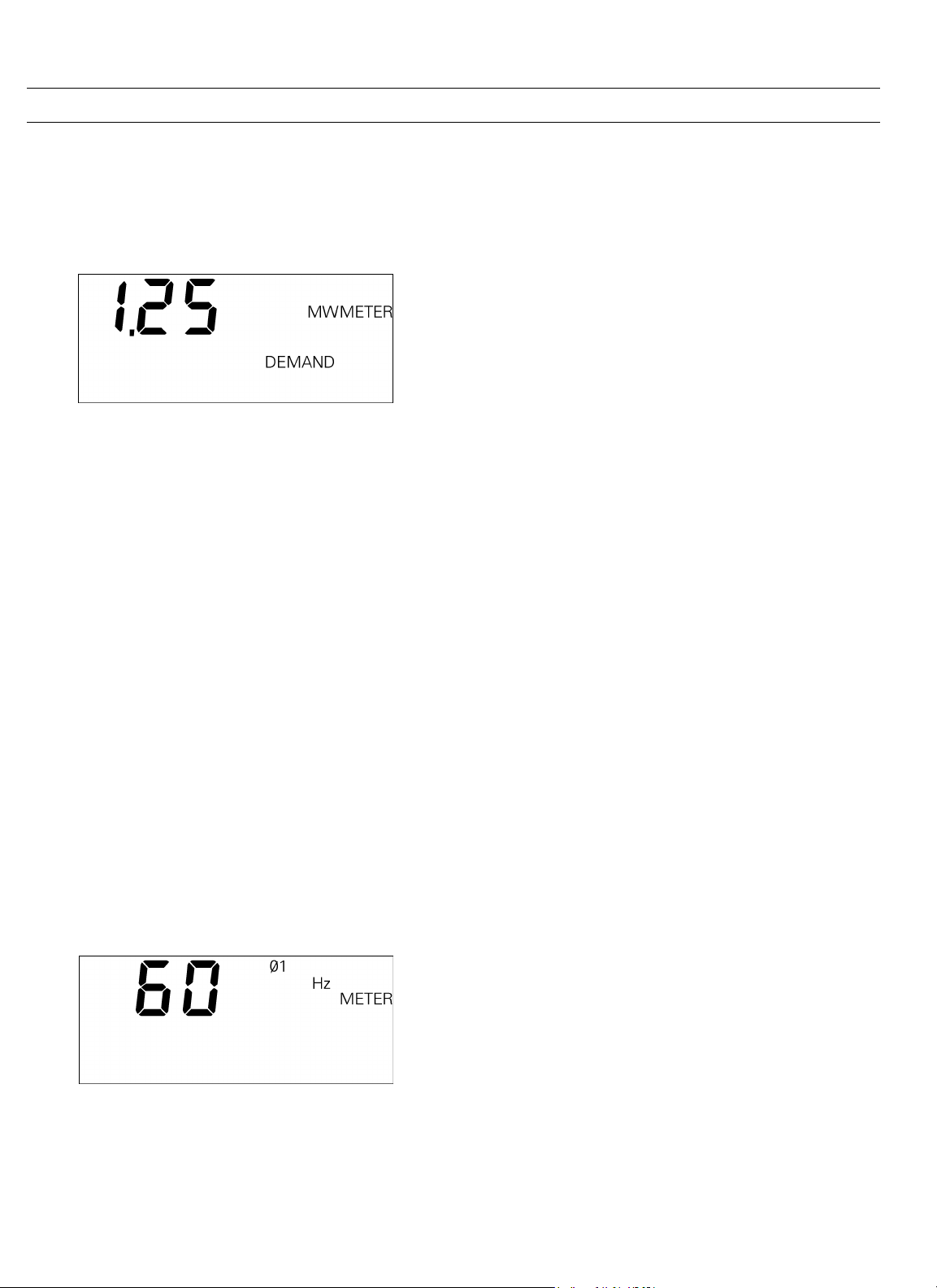
Power Demand
Power demand is the average of total power over the
selected interval (5, 10, …, 55, 60 minutes). This display is
updated every minute. The power demand display is illustrated in Figure 48.
Figure 48. Trip Unit display for power demand.
Peak Power Demand
Peak power demand is stored in nonvolatile memory.
Every minute, the power demand is calculated and compared against the stored peak power demand. If the new
power demand is greater than the stored peak demand,
the Trip Unit stores the new power demand as the peak
value. The display of peak power demand is identical to
the display illustrated in Figure 48, except that the units
segment (in this case, MW) flashes.
Peak demand is stored in nonvolatile memory. The value
in the display can be reset through the Trip Unit keypad.
To reset the peak demand to the present demand, hold
down the VALUE key and press the SELECT key.
Frequency
This display, illustrated in Figure 49, shows the frequency
of the line current. Either line voltage or current must be
present for this display to appear.
The frequency is calculated from the current and voltage
signals. If both are present, the voltage frequency is displayed. If neither are present, this display does not appear.
The frequency is displayed in steps of 1 Hz.
Figure 49. Trip Unit display for frequency.
24
Page 33

MicroVersaTrip Plus™ and MicroVersaTrip PM™ Trip Units
4-1 Overview
Trip Unit Status mode is selected by pressing the
FUNCTION key until STATUS appears on the display. Status
mode indicates the present status of the Trip Unit and
circuit breaker. It also displays information about trip
conditions and the trip history of the breaker. Two categories of information can be displayed: trip information
and trip operations counters.
Trip Information
Various trip information parameters are displayed when
an overcurrent trip or protective relay trip occurs.
The Status display indicates when a long trip is imminent
(breaker is in pickup). Following a trip, the Trip Unit displays a trip target to indicate the type of trip, the fault current magnitude at trip, and the phase of the fault (where
appropriate). For adjustable-instantaneous trips, the Trip
Unit displays the instantaneous function setpoint rather
than the actual current.
Chapter 4. Status Mode
Figure 50. Trip Unit display for normal status.
Long-Time Overcurrent Pickup Display
When the long-time overcurrent function has reached
95% of the Trip Unit’s long-time current rating, xLT,
PICKUP begins to flash on the display, as illustrated in Fig-
ure 51. During the transition from 95% to 100% of the set
point, the frequency of flashing increases. When the set
point is reached, but before the time delay has expired, the
flashing stops, indicating that tripping is imminent.
Trip information is stored in the Trip Unit memory and
displayed when Trip Unit power is returned or if internal
battery power is enabled. Trip information is always available if Trip Unit power is maintained following a fault.
The Status display records trip information only for those
options ordered with the Trip Unit. For example, only
MicroVersaTrip PM Trip Units can be equipped with protective relays and thus display information about them.
Trip Operations Counters
Trip operations counters record the total number of overcurrent trips. Separate internal counters are provided for
each of the following types of trips: long-time, short-time,
adjustable-instantaneous, and ground-fault. The corresponding counter is incremented after any of these trips. A
maximum of 256 trips can be counted for each type of
fault, after which the counter rolls over to zero.
4-2 Status Mode Operation
This section describes each of the Status mode displays.
Normal Status Display
When the breaker is closed and its circuit energized, the
normal status display appears, as illustrated in Figure 50.
This display indicates that the Trip Unit is not in longtime pickup and that all trip targets are cleared.
Figure 51. Trip Unit status display for long-time overcurrent pickup.
Trip Target and Fault Displays
When the breaker trips, information about the trip can be
displayed in Status mode. Figure 52 illustrates a typical
fault display following a trip.
Figure 52. Typical fault display following a breaker trip.
The FAULT segment indicates that the breaker has tripped
because of an overcurrent condition or a protective relay.
This segment remains visible until it is cleared, including
displays in Setup and Meter mode. This provides an indication that trip information is available, even if other
screens are being displayed. If the trip was caused by a
25
Page 34
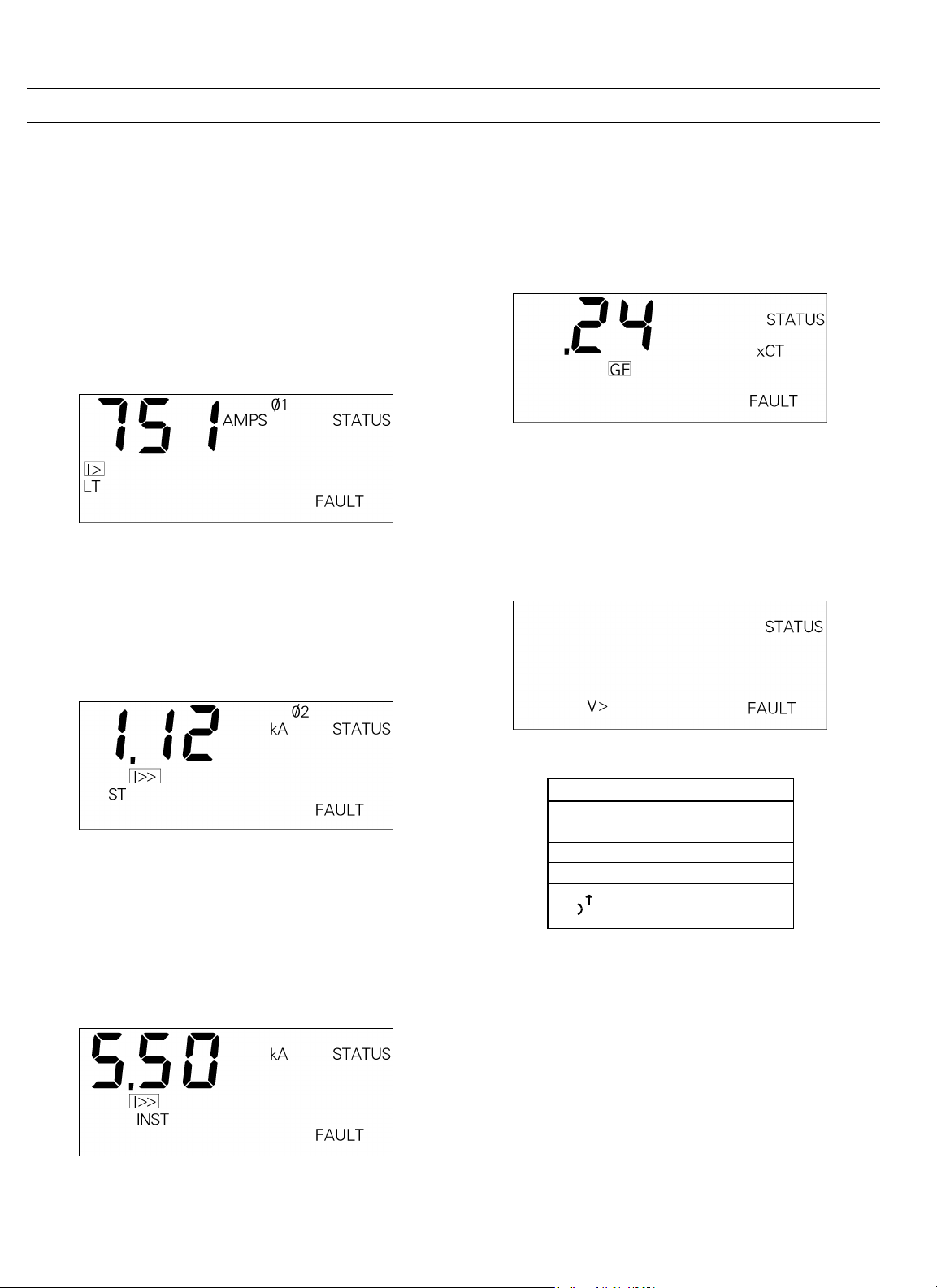
MicroVersaTrip Plus™ and MicroVersaTrip PM™ Trip Units
I
Chapter 4. Status Mode
protective relay, the FAULT segment flashes in Setup or
Meter mode. After an overcurrent trip, the FAULT segment
and the appropriate overcurrent target are displayed in all
modes, without blinking, until cleared.
Long-Time Overcurrent Fault Display
After a long-time overcurrent trip, the trip information
display contains the fault current magnitude at trip, the
phase on which the fault occurred, and the overload (I>)
and long-time (LT) trip targets. This display is illustrated
in Figure 53.
Figure 53. Trip Unit Status display for long-time overcurrent trip.
Short-Time Overcurrent Fault Display
After a short-time trip, the status display appears as in Figure 54. The information presented is similar to that in the
long-time overcurrent display, with the short-circuit (I>>)
and short-time (ST) targets.
Ground-Fault Display
When a ground-fault trip occurs, the display illustrated in
Figure 56 appears. The fault current is displayed in units
of xCT, the breaker CT sensor rating. Multiply the sensor
rating of the breaker by the displayed fault current multiplier to obtain the ground-fault current at trip.
Figure 56. Trip Unit status display for ground-fault trip.
Protective-Relay Fault Display
After a protective-relay trip, the display indicates FAULT
with a target for the type of relay that initiated the trip.
This is illustrated in Figure 57 for an overvoltage trip. The
targets for the five protective relays are listed in Table 16.
Figure 54. Trip Unit status display for short-time overcurrent trip.
Instantaneous Fault Display
The status display for an adjustable instantaneous trip is
illustrated in Figure 55. Because of the fast response of this
function, the Trip Unit displays only the threshold current
for the fault, not the actual fault current nor the phase on
which the fault occurred.
Figure 55. Trip Unit status display for instantaneous overcurrent trip.
Figure 57. Trip Unit status display for protective-relay trip.
Code Protective Relay
∆V Voltage unbalance
∆I Current unbalance
V< Undervoltage
V> Overvoltage
Power reversal
I
Table 16. Trip Unit display targets for protective relays.
Clearing the Trip Information
Since trip information is stored in nonvolatile memory, the
Trip Unit continues displaying the trip information until it
is manually cleared or a new trip occurs. After the trip
information has been recorded or reviewed, it can be
cleared with the keypad. With the Trip Unit in Status
mode, hold down the VALUE key and press the SELECT
key. The trip information is then cleared and the display
reverts to STATUS OK, as in Figure 50.
26
Page 35
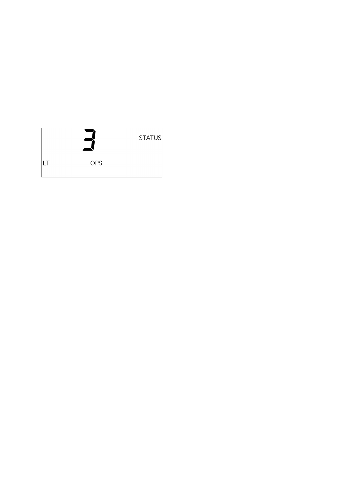
MicroVersaTrip Plus™ and MicroVersaTrip PM™ Trip Units
Trip Operations Counter Display
Trip operations counters record the total number of overcurrent trips. To review any of the trip operations counters
while in Status mode, press the SELECT key until the
desired count appears. Figure 58 illustrates a typical trip
operations counter display. This example indicates that
there have been three long-time trips on this breaker since
the counter was last reset.
Figure 58. Trip Unit status display for long-time overcurrent trip
counter.
Clearing the Trip Operations Counters
Chapter 4. Status Mode
Since the trip operations counters are stored in nonvolatile
memory, the Trip Unit maintains the information
indefinitely. To clear a particular counter, first display the
corresponding count, then hold down the VALUE key and
press the SELECT key. The trip counter is reset to zero.
27
Page 36

MicroVersaTrip Plus™ and MicroVersaTrip PM™ Trip Units
Chapter 5. Maintenance and Trouble-Shooting
MicroVersaTrip Plus and MicroVersaTrip PM Trip Units
and rating plugs are factory tested and normally shipped
installed in their breaker frame assemblies or as part of a
conversion kit. There is no requirement for periodic
maintenance of the Trip Units. There are no user-serviceable
components within the Trip Units.
5-1 Trip Unit Removal and Replacement
Rejection pins are installed on the rear of all Trip Units to
prevent installation of an incorrect Trip Unit into a
breaker. Do not use excessive force when installing a Trip
Unit. Replacement of a Trip Unit always requires repeating the setup procedures, as described in Chapter 2.
WARNING: Before beginning this procedure, turn the
breaker off, disconnect it from all voltage sources, and
discharge the closing springs.
AVERTISSEMENT: Avant de commencer cette procédure,
mettre le disjoncteur en position off, le déconnecter de
toute tension d’alimentation, et décharger les ressorts de
fermeture.
1. Open the breaker and remove it from the cubicle or
substructure. Place it on a suitable work surface. Note
that 3200–5000 A frame breakers must be suitably
supported so that the spring discharge mechanism is
not engaged.
2. Insert the Racking Handle (catalog number
568B731G1) and move the racking mechanism to the
TEST position, as shown on the draw-out position
indicator.
3. Remove the four screws securing the trim plate on the
breaker, then remove the trim plate.
4. Remove the six screws securing the escutheon to the
breaker. Pull the manual charging handle out partway, then slide off the escutcheon.
5. Pull out the locking slide on the right of the Trip
Unit mounting plate, then pull the Trip Unit out,
carefully disengaging the pins on the rear connector.
out partway, then slide the handle through the slot in
the escutcheon and move the escutcheon into place.
Insert the six mounting screws and tighten to 14–20
in-lb.
3. Replace the trim ring around the escutcheon, with
the narrow side at the bottom. Insert the four mounting screws and tighten to 14–20 in-lb.
4. Insert the Racking Handle and return the racking
mechanism to the DISC position, as shown by the
draw-out position indicator.
5. Reinstall the breaker into its cubicle or substructure.
5-2 Rating Plug Removal and Replacement
CAUTION: Removal of the rating plug while the breaker
is carrying current reduces the breaker’s current-carrying
capacity to approximately 25% of the current sensor rating.
ATTENTION: Si le calibreur est retiré le disjoncteur et
traversé par un courant, le niveau de protection s’ajuste à
approximativement 25% du calibre du transformateur
d’intensité.
Interchangeable rating plugs are removed with a Rating
Plug Extractor, Catalog No. TRTOOL. (Suitable equivalents are commercially available as “integrated circuit
(DIP) extractors.”) Grasp the rating plug tabs with the
extractor and pull the plug out as illustrated in Figure 59.
Be sure to grab the tabs and not the front cover of the rating plug, or the plug may be damaged.
Rejection features are provided on all rating plugs to prevent application mismatches. Never force a rating plug
into place. Refer to Chapter 1 to find the appropriate rating plugs for each sensor rating and breaker frame.
If a replacement rating plug has a different rating than the
plug that was removed, follow the appropriate setup
procedure in Chapter 2 to enter the new rating.
To reinstall the Trip Unit, perform the following procedure:
1. Pull out the locking slide on the right of the mounting plate. Push the Trip Unit into place, carefully
engaging the 50-pin connector and lining up the
rejection posts on the rear of the Trip Unit with the
holes in the mounting plate. Release the locking
slide.
2. Check that the breaker racking mechanism is still in
the TEST position. Pull the manual charging handle
28
Page 37

MicroVersaTrip Plus™ and MicroVersaTrip PM™ Trip Units
Chapter 5. Maintenance and Trouble-Shooting
Figure 59. Removing the interchangeable rating plug.
29
Page 38

MicroVersaTrip Plus™ and MicroVersaTrip PM™ Trip Units
Chapter 5. Maintenance and Trouble-Shooting
5-3 Trouble-Shooting Guide
The following guide is provided for trouble-shooting and
isolating common problems. It does not cover every possible condition. Contact the Customer Support Center at
800-843-3742 if the problem is not resolved by these procedures.
Symptom Possible Cause Corrective Action
1. The Trip Unit display is
blank.
Line current is below 20% of the
breaker sensor rating
(MicroVersaTrip Plus).
External +24 Vdc is absent
(MicroVersaTrip PM).
At least 20% of the current sensor rating, xCT, must be flowing
through the breaker to activate the display. If not, power the Trip
Unit with the internal battery or the Portable Power Pack. The
battery power supply is disabled when any current is sensed
through the current sensors.
Check that the auxiliary power supply is present and operational.
2. The Trip Unit display
flashes.
3. The Trip Unit display flashes
ERR.
4. The trip indication target will
not clear.
5. Unit does not communicate
with the Modbus Monitor or
the Power Management
Control System
6. Current readings are
incorrect.
7. Voltage readings are
incorrect.
8. The display is blank or the
Low Battery symbol appears
when the BATTERY key is
pressed.
Can occur on Plus-style Trip Units
when the load current fluctuates near
20% of the breaker sensor rating.
The built-in self test has detected an
error.
Trip Unit is not in Status mode. Press FUNCTION until STATUS is displayed. Hold down the
The communication wires are shorted
or improperly connected.
The Trip Unit address is incorrect.
The rating plug value was defined
incorrectly.
The potential transformer (PT)
primary voltage was defined
incorrectly.
The PT connection was defined
incorrectly.
The battery is discharged. Replace the battery.
Power the Trip Unit with the internal battery or the Portable
Power Pack.
Replace the Trip Unit.
VALUE key and press the SELECT key to clear the target.
Locate and repair the short or the incorrect connection.
Check that the address assigned to the Trip Unit, as in Chapter 2,
agrees with the address at the host.
Read the X value from the rating plug name plate and enter this
as the xIn value with the rating plug current set point procedure
in Chapter 2. Do not enter the sensor rating, S.
Read the PT primary rating from the PT name plate and enter this
value with the PT primary voltage procedure in Chapter 2.
Follow the PT connection procedure in Chapter 2 to enter Ph-N
for a wye-connected PT primary or Ph-Ph for a delta-connected
PT.
30
Page 39

Page 40

g
General Electric Company
510 East Agency Road, West Burlington, IA 52655
DEH178 R01 1297 © 1997 General Electric Company
GE Industrial Systems
 Loading...