

GE Industrial Solutions WattStation Pedestal EVSE Charger Operation and Maintenance User Manual

WattStation™ EV Charer User Manual
GE Energy
TM
GE WattStation
EVSE Charger
Operation and Maintenance
Pedestal

WattStation™ EV Charger User Manual
CONTENTS
1 Safety and Compliance................................................................................................................................................................4
1.1 Important Safety Instructions...................................................................................................................................................4
1.2 FCC Requirements..........................................................................................................................................................................5
2 Notes.....................................................................................................................................................................................................5
3 Features ..............................................................................................................................................................................................6
3.1 Overview .............................................................................................................................................................................................6
3.1.1 Cable reel............................................................................................................................................................................................7
3.1.2 Cable edge guard ...........................................................................................................................................................................7
3.1.3 Plug........................................................................................................................................................................................................7
3.1.4 Dome (Base).......................................................................................................................................................................................7
3.1.5 Shell.......................................................................................................................................................................................................7
3.1.6 Inlet........................................................................................................................................................................................................7
3.1.7 Maintenance Access Door..........................................................................................................................................................7
3.1.8 IP Address Reset..............................................................................................................................................................................7
3.1.9 Removable Top Assembly...........................................................................................................................................................8
3.1.10 LED Ring ..............................................................................................................................................................................................8
3.1.11 Top Cover............................................................................................................................................................................................9
3.1.12 Back-lit Icons.....................................................................................................................................................................................9
3.1.13 RFID swipe indicator...................................................................................................................................................................11
3.1.14 QR Code............................................................................................................................................................................................11
3.2 Communication Options ..........................................................................................................................................................12
3.2.1 Integrated Ethernet communications port......................................................................................................................12
3.2.2 Integrated WiFi Module option..............................................................................................................................................12
3.2.3 Cellular router option.................................................................................................................................................................12
3.2.4 Payment...........................................................................................................................................................................................13
3.3 Electronics.......................................................................................................................................................................................13
3.3.1 Supplemental overload Protection......................................................................................................................................14
3.3.2 Ground Fault protection...........................................................................................................................................................14
3.3.3 Ground Monitor Interrupter ....................................................................................................................................................14
3.3.4 Ventilation Fault............................................................................................................................................................................14
3.3.5 Metering ...........................................................................................................................................................................................14
3.3.6 RFID ....................................................................................................................................................................................................14
3.4 GE WattStation Connect...........................................................................................................................................................14
3.4.1 Status.................................................................................................................................................................................................15
3.4.2 Building Management Systems............................................................................................................................................15
3.4.3 Firmware Updates
3
.5 Technical Details..........................................................................................................................................................................16
4 Operation.........................................................................................................................................................................................17
4.1 Basic Operational Overview....................................................................................................................................................17
4.2 Configuration.................................................................................................................................................................................17
4.2.1 Connecting to Configuration Tool........................................................................................................................................17
4.2.2 Accepting Connection to the Configuration Tool..........................................................................................................20
4.2.3 Using the Configuration Tool..................................................................................................................................................24
4.2.4 Common Settings tab................................................................................................................................................................27
4.2.5 Authorization Options................................................................................................................................................................29
4.2.6 GE WattStation Connect Options.........................................................................................................................................31
.......................................................................................................................................................................15
2 GE Energy ©2012 GE Company All Rights Reserved

WattStation™ EV Charger User Manual
4.2.7 Modbus Options ...........................................................................................................................................................................32
4.2.8 Network Settings..........................................................................................................................................................................33
5 Networking .....................................................................................................................................................................................35
5.1 Overview ..........................................................................................................................................................................................35
5.2 Terms & Definitions.....................................................................................................................................................................35
5.3 Network Topologies....................................................................................................................................................................37
5.3.1 Basic Topologies...........................................................................................................................................................................37
5.3.2 Intermediate Topologies...........................................................................................................................................................39
5.3.3 Advanced Topologies.................................................................................................................................................................41
5.4 Firewall and security considerations..................................................................................................................................46
5.4.1 Firewalls ...........................................................................................................................................................................................46
5.4.2 Proxy Servers .................................................................................................................................................................................46
6 Kits ......................................................................................................................................................................................................47
6.1 Pedestal Assembly Catalog Numbers................................................................................................................................47
6.2 Replacement kits..........................................................................................................................................................................47
7 Maintenance Notes.....................................................................................................................................................................48
8 Trouble shooting ..........................................................................................................................................................................51
8.1 Fault Icon flash codes................................................................................................................................................................51
8.2 Hard Faults .....................................................................................................................................................................................51
8.3 Soft faults.........................................................................................................................................................................................52
8.4 Alarms ...............................................................................................................................................................................................53
9 LIMITED WARRANTY FOR GE WattStationTM (Pedestal) (“this Warranty”) ....................................................56
3 GE Energy ©2012 GE Company All Rights Reserved

WattStation™ EV Charger User Manual
Safety and Compliance
1.1.1 Important Safety Instructions
WARNING:
• Read all the instructions before using this product.
• Do not put fingers into the electric vehicle connector.
• Do not use this product if the flexible power cord or EV cable is frayed, has broken insulation, or
shows any other signs of damage.
• Do not use this product if the enclosure or the EV connector is broken, cracked, open, or shows
any other indication of damage.
• To reduce the risk of fire, replacement fuses should be of the same type and rating.
• Risk of Explosion. This equipment has internal arcing or sparking parts which should not be
exposed to flammable vapors. It should not be located in a recessed area or below floor level
• This device is intended only for charging vehicles not requiring ventilation during charging
• The Electric Vehicle Supply Equipment (EVSE) must be connected to a centrally grounded system.
The ground conductor entering the EVSE must be connected to the equipment grounding lug
inside the charger. This should be run with circuit conductors and connected to the equipment
grounding bar or lead on the EVSE. Connections to the EVSE are the responsibility of the installer
and purchaser, not GE and must comply with all applicable electrical codes and ordinances.
• Risk of electric shock. Do not remove cover or attempt to open the enclosure. No user serviceable
parts inside. Refer servicing to qualified service personnel.
4 GE Energy ©2012 GE Company All Rights Reserved

Reeff.. NNoo..
WattStation™ EV Charger User Manual
1.1.2 FCC Requirements
Note: This equipment has been tested and found to comply with the limits for a Class A digital device,
pursuant to part 15 of the FCC Rules. These limits are designed to provide reasonable protection
against harmful interference when the equipment is operated in a commercial environment. This
equipment generates, uses, and can radiate radio frequency energy and, if not installed and used in
accordance with the instruction manual, may cause harmful interference to radio communications.
Operation of this equipment in a residential area is likely to cause harmful interference in which case
the user will be required to correct the interference at his own expense.
Important:
affect the EMC compliance and revoke your authority to operate this product.
Exposure to Radio Frequency Energy: The radiated power output of the optional IEEE 802.11b/g
wireless radio and optional cellular modem in this device are below the FCC radio frequency exposure
limits for uncontrolled equipment. This device should be operated with a minimum distance of at
least 20 cm between the IEEE 802.11b/g wireless and Cellular antennas and a person’s body and
must not be co-located or operated with any other antenna or transmitter by the manufacturer,
subject to the conditions of the FCC Grant.
Changes or modifications to this product not authorized by GE Industrial Solutions could
2 Notes
This manual is designed to provide you commissioning, preventative maintenance, trouble-shooting and
proper operating instructions for your GE WattStation Pedestal EVSE charger unit. A complete review is
suggested prior to installation and subsequent operation of the product.
Reference Documents
R
DEH -41579 WattStation Pedestal Installation Manual
DEH-41581 WattStation Pedestal MODBUS Register Mapping
Before proceeding to the instructions note that throughout this manual are several warnings, cautions and
notes which are highlighted in bold letters. Please take time to read these special instructions because they
contain important information regarding protection and safety of personnel and equipment.
TTiittllee
5 GE Energy ©2012 GE Company All Rights Reserved
WattStation™ EV Charger User Manual
Owners should contact 1-888-GE-RESOLVE or wattstation.support@ge.com for any operational issues with
WattStation.
Users should contact 1-855-4GE-EVSE for any issues.
The following symbols are used for important safety information in this document:
WARNING:: Denotes operating procedures and practices that may result in
personal injury or loss of life if not correctly followed
CAUTION: Denotes operating procedures and practices that, If not strictly
observed, may result in damage to, or destruction of equipment.
NOTE: Notes call attention to information that is especially significant in
understanding and operating the equipment.
3 Features
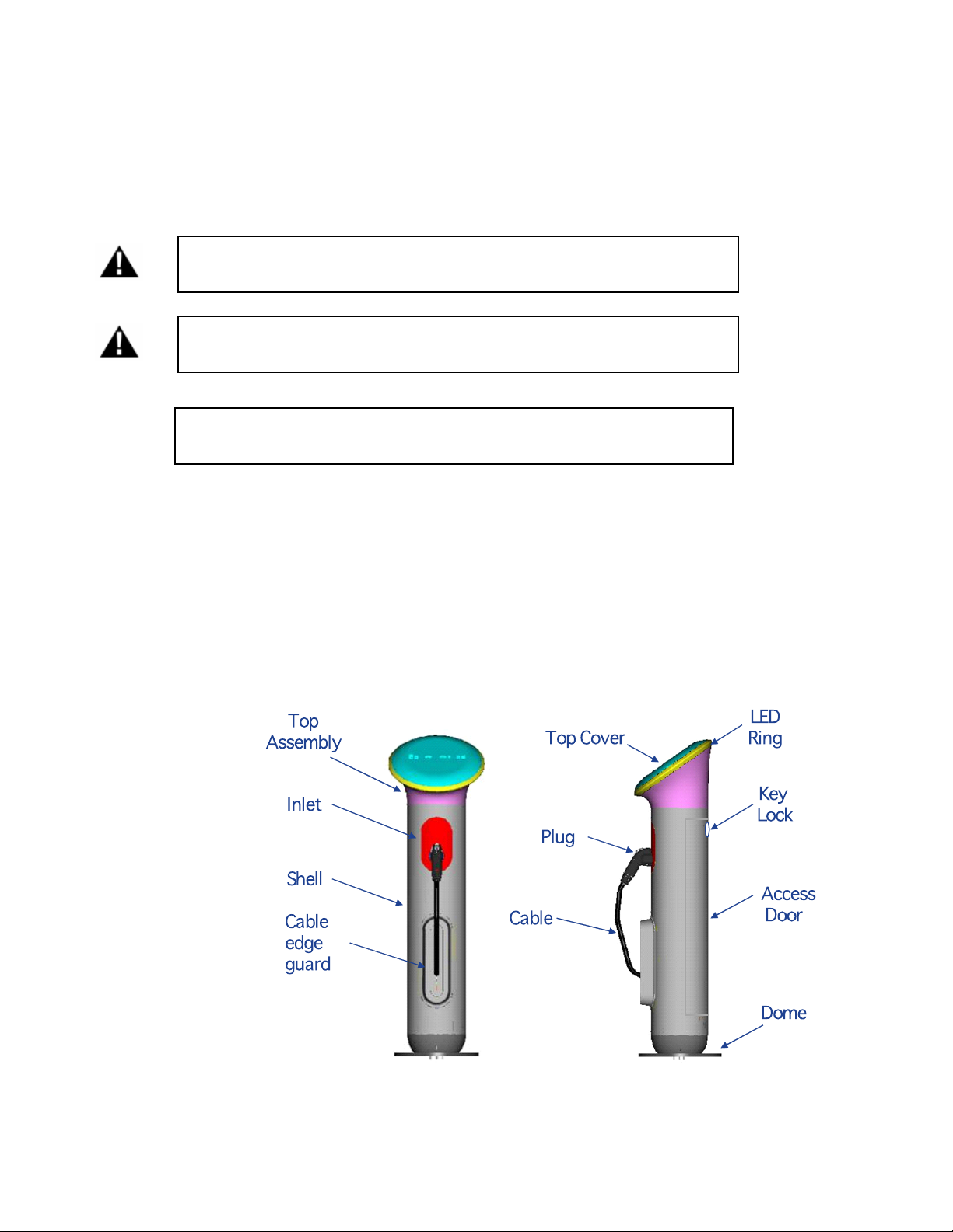
3.1 Overview
The WattStation
current rating. This product will be floor/ground mounted and designed to reside indoors or outdoors (NEMA
type 3R enclosure)
Pedestal is a SAE J1772TM compliant Level 2 (208 – 240VAC) EVSE and has a 30A maximum
Figure – 3.1
6 GE Energy ©2012 GE Company All Rights Reserved

WattStation™ EV Charger User Manual
3.1.1 Cable reel
WattStation Pedestal unit comes with a retractable cable reel with a 15’ 6” cable. The cable will stop
retracting when plugged into a vehicle.
1. Cable should not be extended beyond the red indicator line at the end of the cable. Pulling beyond this indicator
may cause the cable reel to bind, prohibiting retraction.
2. If cable becomes bound due to over-extension, the following steps must be followed to retract the cable before
returning to normal operation
[2.1] Turn off the power
[2.2] Open the access door
[2.3] Manually rotate the cable reel in a counter-clockwise direction until the cable is fully retracted.
3.1.2 Cable edge guard
[2.4] Power up the unit as normal, unit can be returned to normal operation
The cable edge guard protects the cable from rubbing against the metal surface of the shell.
3.1.3 Plug
The Pedestal WattStation has a SAE J1772
feature which allows the user to lock the connector to the vehicle or pedestal
3.1.4 Dome (Base)
The pedestal must be mounted to the ground or floor only.
3.1.5 Shell
The Shell houses the major electrical and communication components. It also holds the inlet and the
access door.
3.1.6 Inlet
The inlet allows a user to store the EVSE plug on the front of the unit.
3.1.7 Maintenance Access Door
A maintenance access door is provided on the back side of the pedestal to allow for installers and
electricians to access internal components inside the EVSE. The maintenance access door has a lock
and key to restrict access
3.1.8 IP Address Reset
The WattStation Pedestal comes with a jumper plug to allow a customer to reset the IP address of the
WattStation Pedestal unit to the default settings. This jumper plug is secured to the DC wire harness
and is accessible upon removing the maintenance access door.
WARNING: The customer must remove power to the EVSE before
attempting to open the access door.
After removing power the customer should disconnect the DC harness at the male/female
connection, insert the jumper plug to the top assembly portion of the connection, close the access
door and reboot the EVSE.
TM
compliant connector. The connector has a padlock
7 GE Energy ©2012 GE Company All Rights Reserved
WattStation™ EV Charger User Manual
TTaabbllee –– 33..11
The LED Ring and fault icon will flash RED when the jumper is connected to the DC harness.
After the IP address is reset, the customer must power down the EVSE, remove the
jumper cable, and reboot.
3.1.9 Removable Top Assembly
The plastic top assembly of the EVSE can be removed by an electrician or installer in order to perform
maintenance or upgrades. Opening the access door is required to allow top assembly removal.
WARNING: The customer must remove power to the EVSE before
attempting to open the access door.
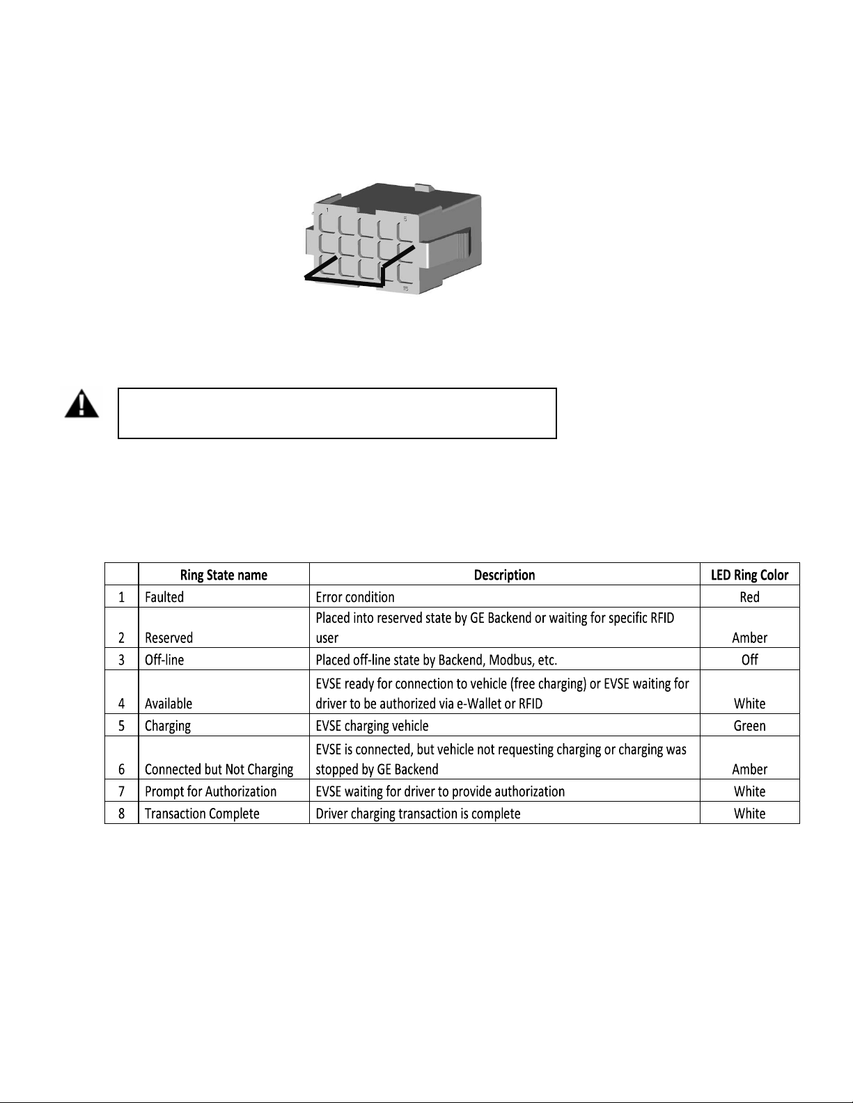
3.1.10 LED Ring
A LED ring will surround the top portion of the EVSE. The LED ring changes color depending on the
EVSE state. Table 3.1 shows the LED ring states and colors. The LED ring can be enabled or disabled
by the EVSE owner via the configuration tool. When the LED Ring is disabled, the LED will still flash
once when initially connected or disconnected from a vehicle
LED Ring state and color
8 GE Energy ©2012 GE Company All Rights Reserved

WattStation™ EV Charger User Manual
3.1.11 Top Cover
The top cover provides EVSE status and instructions to the user. It features several back-lit icons, an
RFID indicator and a QR code.
Top cover assembly
Figure 3.2
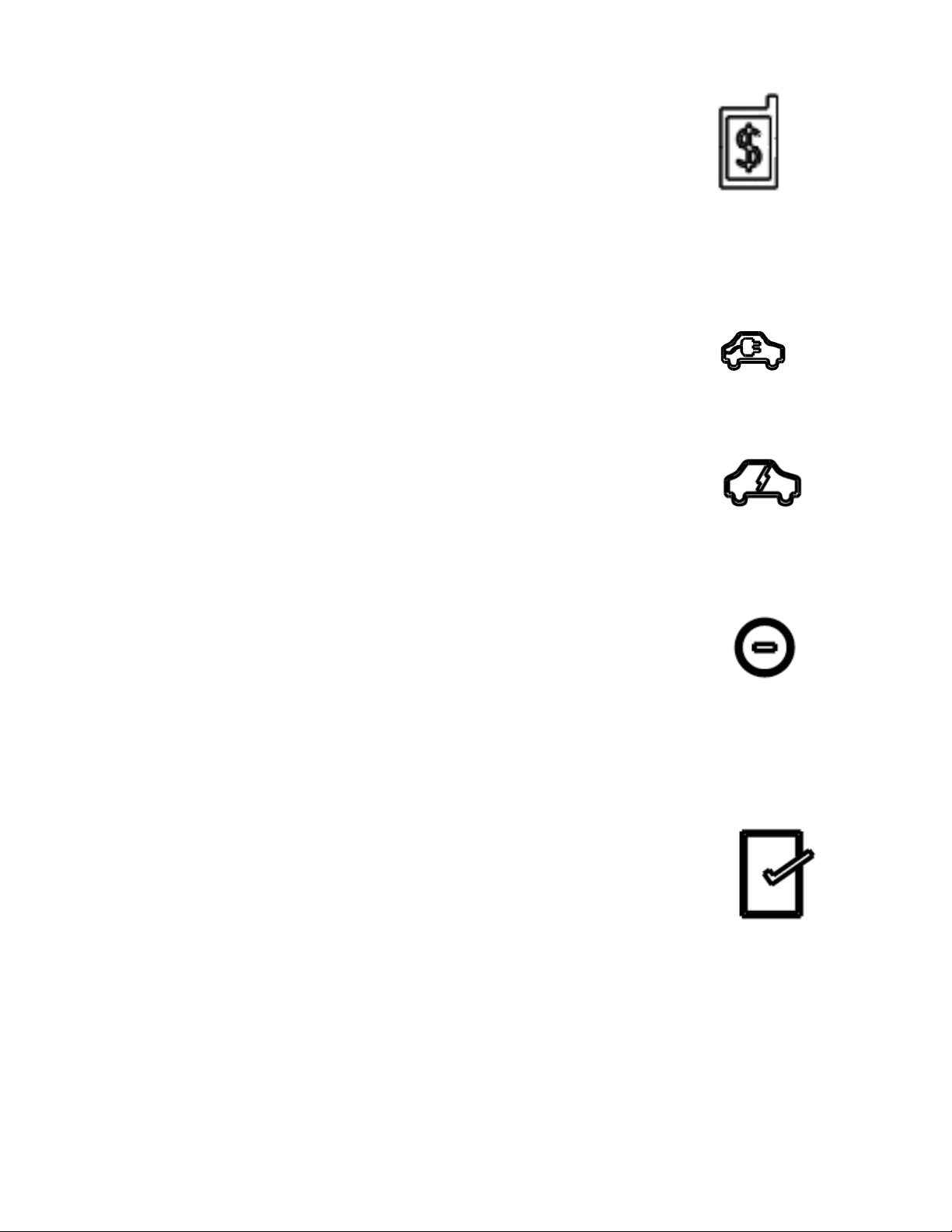
3.1.12 Back-lit Icons
Icon 1: Place RFID card
Solid White: Waiting for user to place
card
Blinking White: Authorizing
Solid Red: Denied
The RFID icon will only be lit if the
Pedestal WattStation is configured for
RFID and the RFID card has not been
swiped or authorized.
9 GE Energy ©2012 GE Company All Rights Reserved
WattStation™ EV Charger User Manual
Icon 2: Payment
Solid White: Waiting for user to initiate
Payment transaction
The Payment icon will only be lit if the
Pedestal WattStation is configured for
Payment option and the Payment
Transaction has not been authorized.
Icon 3: Ready to charge
Solid white when access granted, but not connected to
vehicle. The icon is OFF when not in ready to charge state
Icon 4: Charging
Solid White when charging. The icon is OFF when not in charge
state
Icon 5: Pause
Solid Amber when connected, but waiting for car to request charge.
The Pause icon resides right next to charging icon.
Icon 6: Transaction complete
Solid white when access transaction has completed if the charge
transaction was initiated using a RFID card or Payment. When the
user disconnects the EV connector from the vehicle, the transaction
complete icon will remain lit for 30 seconds before turning off.
Once 30 seconds have passed, the Place card icon will illuminate.
The transaction complete icon is only available if the unit has RFID
and/or a payment system available.
10 GE Energy ©2012 GE Company All Rights Reserved

WattStation™ EV Charger User Manual
Icon 7: Fault
Red when a fault has occurred. The fault icon blinks a unique
pattern that indicates the type of fault that has occurred (see Section
8.1). The fault icon will not illuminate RED if no fault has occurred or
the fault has cleared.
3.1.13 RFID swipe indicator
The RFID swipe indicator is on the top assembly that indicates
where a user should swipe their RFID card.
3.1.14 QR Code
The top assembly of the Pedestal WattStation has a ¾¾”” xx ¾¾”” Quick Response (QR) code label placed
under the top assembly cover, viewable through the top cover. Each QR code holds a unique serial
number in its image. The QR code serial number is stored in the EVSE’s SBC (Single Board Computer).
An EV driver or EVSE owner can use their iPhone and the GE WattStation application to scan the QR
code. Once the QR code is captured, the application will automatically connect to the GE WattStation
Connect and provide the driver or EVSE owner with access and information for the Pedestal
WattStation.
Figure 3.3
11 GE Energy ©2012 GE Company All Rights Reserved

WattStation™ EV Charger User Manual
3.2 Communication Options
The WattStation has different types of TCP/IP communication interfaces to the customer: Cellular router,
integrated WiFi module or CAT5
3.2.1 Integrated Ethernet communications port
TCP/IP communication over an IEEE 802.3 (a.k.a. “Ethernet”) compliant network between the EVSE and
customer network is available in all EVSE models. A single CAT5e or better cable can be run from each
EVSE to a network hub, router or switch in a star configuration. If the star configuration is not desired,
the customer can use the 4 port Ethernet switch that is standard in all EVSE models to daisy chain
CAT5e cables from one EVSE to another.
WattStation Ethernet ports support only 10BASE-T (10 Mbit/s) or 100BASE-TX (100 Mbit/s) network
speeds. Installation on networks running at 1000BASE-T (100 Mbit/s) will require that the networks be
configured to support devices that operate at 100 Mbit/s.
The maximum length of the communication cables is determined by the CAT5e standard, which
stipulates a maximum length of 100 m (328 feet). If longer runs are required, the use of active
hardware such as a repeater or a switch is necessary.
3.2.2 Integrated WiFi Module option
A Pedestal WattStation with WiFi communication incorporates a IEEE 802.11b/g compliant radio
module. EVSE customers that do not select the WiFi communication option will not receive this radio
module. The WiFi module allows the EVSE owner to communicate to their Building Management
System (BMS) or GE WattStation Connect over WiFi. The WiFi module will have a connection to attach
to the EVSE’s WiFi antenna. The WiFi module will support IEEE 802.11 b/g networks. Operation on
IEEE 802.11n networks will therefore require that the networks be configured to support 802.11g
devices. The WiFi module is disabled when shipped and is enabled by first connecting to the
configuration tool via a CAT5 connection.
The IEEE 802.11b/g compliant WiFi radio is certified as an intentional radiator per FCC Part 15 Subpart
C rules and has been granted the following Federal Communication Commission and Industry Canada
(Industrie Canada) identification numbers.
FCC ID U9R-W2CBW009DI
IC ID 7089-W2CBW09D
Note that a Pedestal WattStation that has the WiFi radio and antenna installed cannot utilize the
cellular option.
3.2.3 Cellular router option
The cellular router will provide wireless communication for a single or group of EVSEs over a cellular
provider’s network. A customer can choose to put a cellular router into each EVSE they have at a
location or they can add one cellular router into a group of EVSEs and daisy chain the EVSEs together
using the CAT5.
12 GE Energy ©2012 GE Company All Rights Reserved

WattStation™ EV Charger User Manual
VVeerriizzoonn
Two types of cellular routers are supported offered for the Pedestal WattStation: CDMA/EV-DO and
GSM/HSPA. Both routers will support speeds up to 3G and default to lower speeds when the
maximum is not available. The cellular carrier for the CDMA router is Verizon for US installations and
the cellular carrier for the GSM router is Vodafone for Canada installations. All cellular claims are
based on the US coverage map provided by Verizon and Canadian coverage map from Vodafone.
The cellular router is powered from the EVSE controller. Only one type of the router can be installed in
an individual Pedestal.
GE recommends that customers perform a site survey with a third party to ensure adequate cellular
performance. The exact environmental factors of the location and orientation to the nearest cell
tower strongly affect cellular performance.!
The cellular router is certified as an intentional radiator per FCC Part 15 Subpart C rules and has been
granted the following Federal Communication Commission and Industry Canada (Industries Canada)
identification numbers.
FFCCCC IIDD
IICC IIDD
Note that a Pedestal WattStation that has the cellular router and antenna installed cannot
utilize the WiFi option.
NN77NN--MMCC88779955
22441177CC--MMCC88779955
VVooddaaffoonnee
NN77NN--MMCC88779955
22441177CC--MMCC88779955
3.2.4 Payment
A payment option allows an EVSE owner to provide users who have an online payment account
(PayPal) the ability to charge their vehicle. There are two methods of payments: smartphone (iPhone
or Android) or RFID.
When using a smartphone, the driver shall scan the QR code on the EVSE using the camera on the
smartphone and the GE WattStation Connect smartphone application. The GE WattStation Connect
smartphone application will access the GE WattStation network to show the EVSE owner’s fees for
using the charger to the driver. Once the driver has decided on accepting the EVSE owner’s fees, the
GE WattStation Connect will grant access of the EVSE to the driver.
When using RFID to utilize a driver’s online payment account, the driver will swipe their RFID card
(WattStation Connect Payment Card) at the EVSE. . The driver must first link the WattStation Connect
Payment Card to their PayPal account via the WattStation Connect web application. If the driver
accepts the fees, the GE WattStation Connect will grant access of the EVSE to the driver.
3.3 Electronics
The Electronics Control Unit in the Top Assembly integrates Control Pilot Functions, Metering, Overload
monitoring, ground fault protection and all local monitoring.
13 GE Energy ©2012 GE Company All Rights Reserved

WattStation™ EV Charger User Manual
FCCCC IIDD
3.3.1 Supplemental overload Protection
The controller will open the main power contactor at 125% of nominal current for NEMA.
3.3.2 Ground Fault protection
Pedestal WattStation includes 15 - 20 mA GF protection per UL 2231. The EVSE provides fault
indication if a ground fault has occurred. The fault will automatically reset per UL 2231 if the fault has
occurred after charging has begun. This reset will occur after 15 minutes. Only 4 automatic retries
can occur in a charging session. Unplugging the EVSE connector from the vehicle will close out a
charging session and reset the number of automatic retries. If the ground fault is detected
immediately after charging, the EVSE will stop charging and indicate a fault.
3.3.3 Ground Monitor Interrupter
The EVSE will perform ground monitoring on the line and load side per UL 2231. Ground monitoring
on the load side requires the EVSE to stop or not initiate charging if earth ground is broken between
vehicle and EVSE. Ground monitoring on the line side requires the EVSE to stop initiate charging if
earth ground is not present on the incoming power side of the EVSE. If the ground monitor detects the
loss of ground on the vehicle side of the EVSE, the EVSE will disconnect the contactor if charging or
prevent charging if the vehicle is requesting charge. If the ground monitor detects the loss of ground
on the line side of the EVSE, the LED ring will indicate fault and prevent the EVSE from charging a
vehicle.
3.3.4 Ventilation Fault
If a vehicle requests facility ventilation, the Pedestal WattStation will not charge the vehicle and issue
a fault indication on the LED Ring and fault icon. The fault will be cleared once the EVSE connector is
removed from the vehicle.
3.3.5 Metering
Pedestal WattStation measures the voltage, current, power and Energy consumed by the EV during a
charge and the measured data is available through Modbus or WattStation Connect.
3.3.6 RFID
The RFID reader will scan RFID cards and pass the scanned information to WattStation Connect for
user authorization.
The RFID reader is certified as an intentional radiator per FCC Part 15 Subpart C rules and has been
granted the following Federal Communication Commission and Industry Canada (Industrie Canada)
identification numbers.
F
IICC IIDD
JJQQ66--MMCCLLAASSSS1155NN
22223366BB--MMCCLLAASSSS1155NN
3.4 GE WattStation Connect
GE WattStation Connect is a server application that allows owners to configure and monitor their EVSEs
remotely. GE WattStation Connect also handles RFID authentication and setup. The customer will access GE
WattStation Connect through their web browser on their PC
14 GE Energy ©2012 GE Company All Rights Reserved

WattStation™ EV Charger User Manual
Noottee::
3.4.1 Status
GE WattStation Connect will provide EVSE status to customers. The customer will receive these
updates through their web browser, text message and/or email. Here is a list of status updates the
customer will receive:
• Algorithm Status
• History/Reporting
• Actual current draw by each group member
- Summary of current draw for the entire group
- Max current renegotiated
- Algorithm settings committed
- Algorithm enabled/disabled
- Internal EVSE temperature
• Monitoring
- EVSE state: disconnected, connected, charging and fault
- Internal EVSE temperature
• Control
- Scheduled charging
- Override of charging
- Charging delay
• Diagnostics
- Ground fault
- Loss communication
- RFID failure
- Un-authorized users
- Contactor monitor
- Overload
- Over/Under voltage
- Invalid payment
- Additional fault diagnostics
3.4.2 Building Management Systems
The Pedestal WattStation will communicate to building management systems (BMS) via Modbus over
the CAT5 connection or WiFi. The EVSE comes with a Modbus register map that the BMS integrator
can integrate into their SCADA or server system(s).
N
Static IP addressing should be used for the WattStation(s) and all Modbus clients.
3.4.3 Firmware Updates
The firmware for the EVSE will be upgradeable over the EVSE’s TCP/IP interface (CAT5 or wirelessly
through the cellular router or WiFi Access Point). The firmware updates will allow GE to supply
customers with updated firmware that adds additional features to flexible charging algorithms,
ground fault detection performance, pricing models, communication protocols and other
performance enhancements. All firmware updates will be accessed and controlled through the GE
WattStation Connect.
15 GE Energy ©2012 GE Company All Rights Reserved

WattStation™ EV Charger User Manual
3.5 Technical Details
SAE Compliant Level II per J1772
Vehicle Interface SAE J1772 EV connector
Cable Length 15’ 6” cable
AC Max Charging Power Output** 7.2 kW (240VAC @ 30A)
Voltage and Rated current 208-240VAC @ 30A
AC Power Input
Short Circuit Rating 5kA @ 240 VAC
Recommended Service Panel
Breaker
Ground Fault Protection
Cold Load Start Random start up between 0 and 5 minutes
Local Area Network IEEE 802.3 (“Ethernet”) compliant: 10BASE-T, 100BASE-TX
Network Communication Protocol TCP/IP
Network Security GE recommends that network be VPN and Firewall protected
Cellular Router (Optional) EV-DO / HSPA
WiFi (Optional) IEEE 802.11b/g compatible with Antenna
Metering Accuracy < +/-2% accurate for all values (Current, Voltage, Power & Energy)
RFID Reader HID MultiClass RP15
Display LED Icon
Standby Power 25W typical
Outdoor Rated Enclosure NEMA 3R
Safety Compliance
Surge Protection 6kV @ 3000A
EMI Compliance FCC Part 15 Class A
Operating Temperature
Operating Humidity Up to 95% non-condensing
Approximate Shipping Weights 120 lb
Dimensions 51”H x 15”Dia
Table – 3.2
208-240VAC requiring only Line 1 and Line 2, or Line and Neutral,
and Earth ground
2-pole 40A breaker on dedicated circuit
Internal 20mA CCID with auto-re-closure, does not require a GFCI
in service panel
UL 2231, UL 2251, UL 2594, cUL 2231, cUL 2594, NEC 625, SAE J1772,
ETL and CETL listed
-30°C to +50°C ambient (Operating temp. limit for cord reel is -15
Deg. C)
**The maximum power consumption is determined by EVSE. The actual power consumption
is determined by EV.
16 GE Energy ©2012 GE Company All Rights Reserved

WattStation™ EV Charger User Manual
4 Operation
4.1 Basic Operational Overview
• LED ring on the EVSE WattStation pedestal unit will glow white when the unit is not in use and not
in a faulted or reserved condition.
• Before unplugging the connector from the EVSE, swipe the RFID card (if enabled) to initiate the
charge process. Once the RFID card is recognized the RFID icon on the top cover will glow solid
white and the Ready to Charge icon will be lit.
• Plug the connector into car. The LED ring will turn from white to amber in color. The white
Charging icon will glow and stay lit for the duration of the time the vehicle is connected. The
amber Charging Paused icon will stay lit until charging actually commences, and will glow again
when the vehicle is fully charged or if a Modbus or GE WattStation Connect command has caused
the charge to go into a paused state.
• Once the car is connected and initiated charging, The LED ring on the unit will change from amber
to green and the amber Charging Paused icon on the top cover will turn OFF.
• LED ring on the unit will change from green to amber once the car is fully charged.
• When the vehicle is disconnected, the transaction complete icon will light for 30 seconds. The LED
ring on the unit will change from amber to white color
• The LED ring will turn red if there are any faults occurred, the fault icon blinks in a unique pattern
that indicates the type of fault. Refer to Section 8 for fault codes and troubleshooting details.
4.2 Configuration
4.2.1 Connecting to Configuration Tool
The WattStation Pedestal contains a configuration tool which can be used to establish owner
preferences and to setup the communication parameters for the customer’s network. The initial
connection to the Configuration Tool must be made via the Integrated Ethernet Communications port
(see Section 3.2.1). Subsequent connections to the tool can be made over WiFi after the wireless
network settings have been made to connect to the appropriate network.
The default IP address for the WattStation’s Ethernet communications port depends on whether or
not the cellular option is present. For the purposes of customer convenience, the WattStation is
shipped from the factory with default network setting of “DHCP enabled”. This means that the
WattStation will try to obtain an IP address from a DCHP server if one is available.
17 GE Energy ©2012 GE Company All Rights Reserved
WattStation™ EV Charger User Manual
8
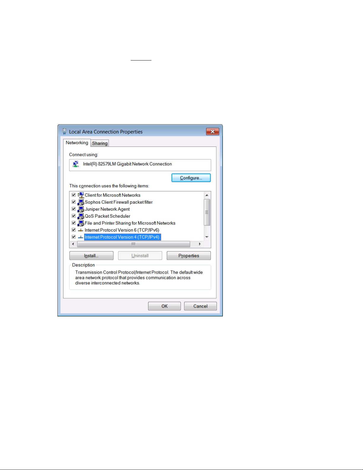
Approach 1:
In the case of WattStation without
network with a DHCP server then it will default to an IP address of 192.168.13.1. Before connecting to
the tool, ensure your computer has an IP address on the same subnet as the WattStation. The
method to do this varies by operating system. Pull up a menu that lets you modify the Local Area
Connection properties (see below). On Windows machines this is done through the Control Panel,
then selecting Network, then selecting Adapter settings. Then right click on Local Area Connection
and select Properties.
the cellular router option, if the WattStation is not connected to a
Figure – 4.1
118
GE Energy ©2012 GE Company All Rights Reserved
 Loading...