

Page 1
GEK–97367C
g
TVRMS2 Digital Test Kit
User’s Guide
Page 2

MicroVersaTrip® Digital Test Kit
Controls, Indicators, and Connections
2
Page 3

WARNINGS
CAUTIONS
GEK–97367C
WARNINGS, CAUTIONS, AND NOTES
AS USED IN THIS PUBLICATION
Warning notices are used in this publication to emphasize that hazardous voltages, currents, or
other conditions that could cause personal injury are present in this equipment or may be
associated with its use.
Warning notices are also used for situations in which inattention or lack of equipment knowledge
could cause either personal injury or damage to equipment.
Caution notices are used for situations in which equipment might be damaged if care is not taken.
NOTES
Notes call attention to information that is especially significant to understanding and operating the
equipment.
This document is based on information available at the time of its publication. While efforts have
been made to ensure accuracy, the information contained herein does not cover all details or
variations in hardware and software, nor does it provide for every possible contingency in
connection with installation, operation, and maintenance. Features may be described herein that
are not present in all hardware and software systems. GE Electrical Distribution & Control assumes
no obligation of notice to holders of this document with respect to changes subsequently made.
GE Electrical Distribution & Control makes no representation or warranty, expressed, implied, or
statutory, with respect to, and assumes no responsibility for the accuracy, completeness, sufficiency,
or usefulness of the information contained herein. No warrantees of merchantability or fitness for
purpose shall apply.
The following are trademarks of GE Company:
MicroVersaTrip®, MicroVersaTrip Plus™, MicroVersaTrip PM™, Spectra RMS™, Power+™
i
Page 4

TVRMS2 Digital Test Kit
Table of Contents
Chapter 1. Introduction
1–1 Description ............................................................................................................................................. 1
1–2 Application to Pre-RMS-9 Trip Units.....................................................................................................1
1–3 Definition of Terms ...............................................................................................................................2
1–4 Test Selection .........................................................................................................................................2
Chapter 2. Controls, Indicators, and Connections
2–1 Front Panel.............................................................................................................................................3
2–2 Top Panel (Test Cable Connection.......................................................................................................3
2–3 Bottom Panel..........................................................................................................................................4
Chapter 3. Initialization and Setup
3–1 Introduction...........................................................................................................................................5
3–2 Initialization and Self-Test.....................................................................................................................5
3–3 Trip Unit Type Selection .......................................................................................................................5
3–4 Test Selection Sequence.........................................................................................................................7
Chapter 4. Power+™, RMS-9, and Epic Trip Units
4–1 Test Structure (Power+™, RMS-9, and Epic)........................................................................................8
4–2 Switch Settings Test................................................................................................................................9
Rating Plug Value (X).....................................................................................................................9
Current Setting (C).........................................................................................................................9
Long Time Delay.............................................................................................................................9
Short Time Pickup and Delay.........................................................................................................9
Instantaneous Pickup (INST).......................................................................................................10
Ground Fault .................................................................................................................................10
Failures ..........................................................................................................................................11
4–3 Self-Test Report....................................................................................................................................11
4–4 Overcurrent Simulation.......................................................................................................................12
Long Time Test.............................................................................................................................12
Short Time Test.............................................................................................................................12
Ground Fault Test .........................................................................................................................12
Overcurrent Simulation Test ........................................................................................................12
4–5 High-Current Primary Injection ..........................................................................................................13
Trip Unit Ground Fault Defeat..................................................................................................... 13
Trip Unit Pickup and Trip Monitor .............................................................................................14
4–6 Trip Unit Quick Test ...........................................................................................................................14
Chapter 5. MicroVersaTrip Plus™ and MicroVersaTrip PM™ Trip Units
5–1 Test Structure (MicroVersaTrip Plus™ and MicroVersaTrip PM™).................................................15
5–2 Pickup Settings .....................................................................................................................................16
5–3 Self-Test Report....................................................................................................................................16
5–4 Overcurrent Simulation.......................................................................................................................16
Long Time Test.............................................................................................................................17
Short Time Test.............................................................................................................................17
Ground Fault Test .........................................................................................................................18
ii
Page 5

TVRMS2 Digital Test Kit
Table of Contents
Overcurrent Simulation Test ........................................................................................................18
5–5 High Current Primary Injection ..........................................................................................................19
Trip Unit Ground Fault Defeat.....................................................................................................19
Trip Unit Pickup and Trip Monitor .............................................................................................20
5–6 Trip Unit Quick Test............................................................................................................................20
iii
Page 6

TVRMS2 Digital Test Kit
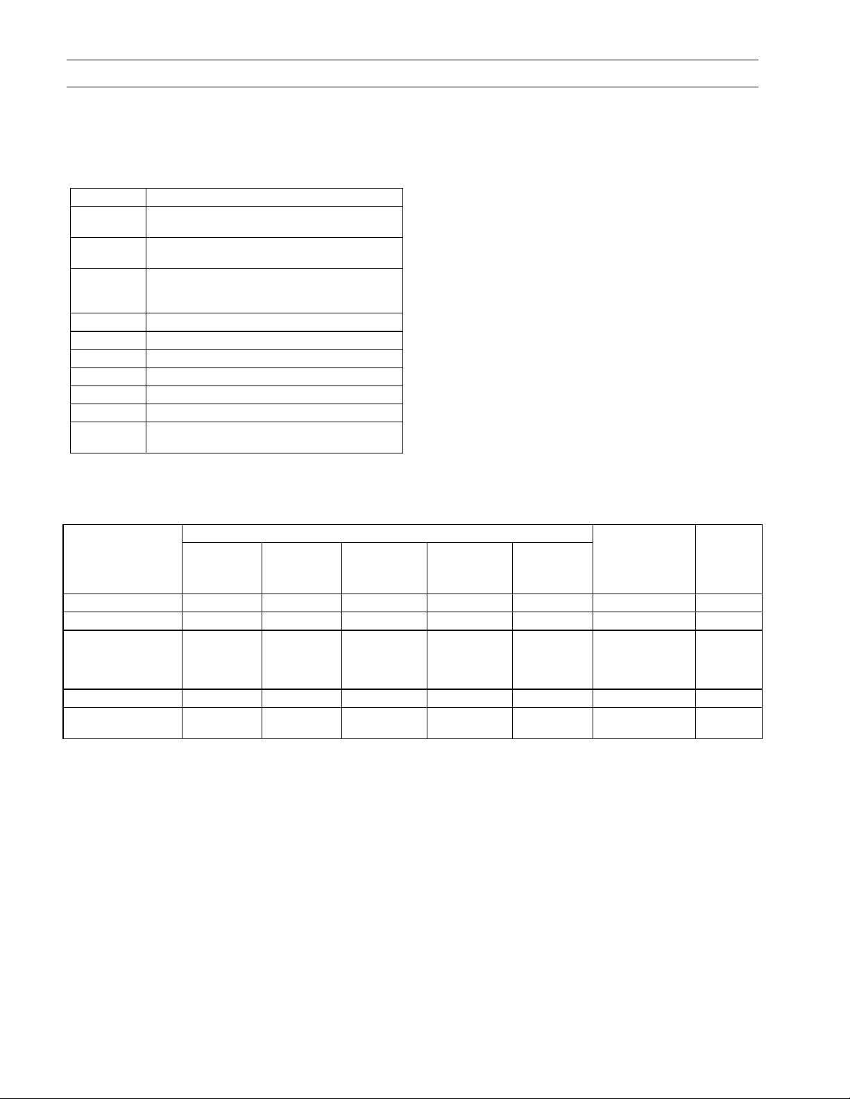
List of Figures and Tables
Figures
1. TVRMS2 Digital Test Kit connected to a MicroVersaTrip PM™ Trip Unit............................................ 1
2. Front panel of the Test Kit........................................................................................................................ 3
3. Bottom panel of the Test Kit, showing the 120 Vac power cord and the battery-storage area. ............... 4
4. Block diagram of Test Kit initialization and Trip Unit selection. ........................................................... 5
5. TS-style Trip Unit (Power+™, RMS-9 and Epic)...................................................................................... 6
6. TT-style Trip Unit (MicroVersaTrip Plus™ and MicroVersaTrip PM™)............................................... 6
7. A-, B-, or C-style Trip Unit (enhanced MicroVersaTrip Plus™ and MicroVersaTrip PM™).................. 6
8. MicroVersaTrip Plus™ and MicroVersaTrip PM™ Trip Units in Spectra RMS™ molded-case
circuit breakers.......................................................................................................................................... 6
9. Power+™ Trip Unit. .................................................................................................................................. 6
10. Test-selection structure for Power+™, RMS-9 and Epic Trip Units. ........................................................ 8
11. Test-selection structure for MicroVersaTrip Plus™ and MicroVersaTrip PM™ Trip Units ................. 15
Tables
1. Matrix showing compatibility among Test Kit models and Trip Unit types............................................ 1
2. Definitions of terms used in this guide..................................................................................................... 2
3. Tests available with the TVRMS2 Digital Test Kit and the functions tested ........................................... 2
iv
Page 7

TVRMS2 Digital Test Kit
Chapter 1. Introduction
1–1 Description
The TVRMS2 Digital Test Kit is a light-weight, portable
test instrument designed for field testing of RMS-9, Epic,
Power+™, MicroVersaTrip Plus™, and MicroVersaTrip
PM™ Trip Units. The Test Kit includes the following
features:
• Operation from 120 Vac or six D-cell batteries.
• Trip Unit testing without de-energizing the breaker
or removing the Trip Unit from the breaker.
• Verification of switch settings on Power+, RMS-9 and
Epic Trip Units.
• Either trip or no-trip testing for time-overcurrent
characteristics.
• Monitoring of pickup current and trip time during
high-current injection testing.
• Menu-driven test procedures for ease of use.
The Test Kit interface with the Trip Unit is a three-wire
digital communication link through the test jack on the
front of the Trip Unit, as illustrated in Figure 1.
1–2 Application to Pre-RMS-9 Trip Units
The TVRMS2 Test Kit cannot be used to test earlier
MicroVersaTrip solid-state programmers. Table 1 is a
matrix showing the compatibility among types of Trip
Units and Test Kit models.
CAUTION: The older TVTS1 Test Kit cannot be used to
test RMS-9, Epic, Power+, MicroVersaTrip Plus, and
MicroVersaTrip PM Trip Units and could cause damage
to the Trip Unit if an attempt is made to do so.
ATTENTION: Ne pas utiliser TVTS1 (modèle précedent)
Test Kit avec les déclencheurs RMS-9, Epic, Power+,
MicroVersaTrip Plus, et MicroVersaTrip PM (le
déclencheur pourrait être endommagé).
CAUTION: The older TVRMS Test Kit cannot be used to
test MicroVersaTrip Plus and MicroVersaTrip PM Trip
Units and could cause incorrect test results if an attempt
is made to do so.
ATTENTION: Ne pas utiliser TVRMS (modèle précedent)
Test Kit avec les déclencheurs MicroVersaTrip Plus et
MicroVersaTrip PM (les résultants peuvent être
incorrects).
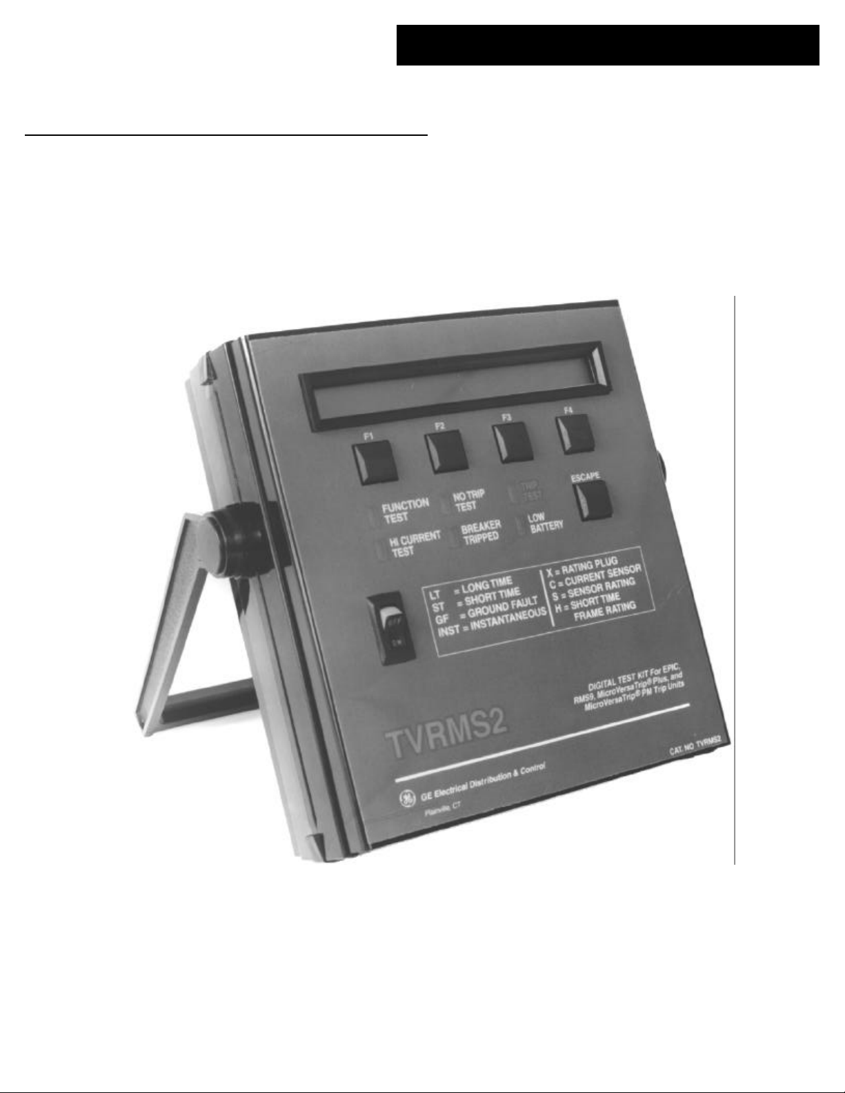
Figure 1. TVRMS2 Digital Test Kit connected to a
MicroVersaTrip PM™ Trip Unit.
Trip Unit Type
Test Kit
TVTS1 Yes No No
TVRMS No Yes No
TVRMS2 No Yes Yes
¿ ANSI and UL applications only.
MicroVersaTrip® TP4VT, TP9VT,
TAVT, and T4VT
RMS9 and Epic (“TS” type)
Power+™ ¿,
MicroVersaTrip Plus™ and
MicroVersaTrip PM™ (“TT” and
“A,B,orC” type) or Spectra RMS™
breaker
Table 1. Matrix showing compatibility among Test Kit models and Trip Unit types.
1
Page 8
TVRMS2 Digital Test Kit
Chapter 1. Introduction
1–3 Definition of Terms
The terms listed and defined in Table 2 are displayed on
the Test Kit and are used throughout this guide.
Term Definition
S,
xCT
X,
xIn
C,
xLT
LT Long Time overcurrent protection function
ST Short Time overcurrent protection function
INST Instantaneous overcurrent protection function
GF Ground Fault overcurrent protection function
H The Short Time rating of the breaker frame.
Trip Test A test that causes the breaker to trip.
No-Trip
Test
Table 2. Definitions of terms used in this guide.
The current sensor rating – the primary
current rating of the breaker’s current sensors.
The current rating of the Trip Unit, set by the
rating plug.
The current setting of the Trip Unit –
determined as a multiplier of the rating plug
value.
A test that does not cause the breaker to trip.
1–4 Test Selection
The Test Kit can perform three types of tests on Trip
Units:
• Function tests verify the operation of the Trip Unit,
including:
– Time-overcurrent tests, both trip and no-trip
– Switch-setting verification (Power+, RMS-9 and
Epic only)
– Trip Unit self-test report
• High-current tests monitor the functioning of the Trip
Unit during primary current-injection testing of the
breaker with a separate, commercially available highcurrent test set. Under high-current tests, the Test Kit
can temporarily suppress or defeat Ground Fault
protection. The Test Kit monitors the time at which
the Trip Unit goes into overcurrent pickup and
displays the overcurrent condition and the time
required to trip.
• Quick test verifies that the Trip Unit and the breaker
mechanism can cause the breaker to trip by actually
tripping the breaker.
The tested functions are listed in Table 3.
Trip Unit
Test Selected
Switch Settings¿ X X X X X
Self-Test X X X
Overcurrent
Simulation:
No Trip
Trip
Quick Test X X
High-Current
(Primary) Injection
¿
RMS-9, Power+, and Epic only.
Function
Switches
X
X
X X X X X X X
A/D
Converter
Micro-
processor
(also ROM &
RAM)
X
X
Nonvolatile
Memory
X
X
Rating Plug
X
X
Flux Shifter
Trip Activator &
Breaker
Tripping
Mechanism
X
Input
Sensors
(CTs)
Table 3. Tests available with the TVRMS2 Digital Test Kit and the functions tested.
2
Page 9
TVRMS2 Digital Test Kit
Chapter 2. Controls, Indicators, and Connections
2–1 Front Panel
Figure 2 shows the front panel of the Test Kit.
Figure 2. Front panel of the Test Kit.
The functions of the various switches and displays on the
front panel are as follows:
• Display Panel – The display panel is a 40-character by
2-line liquid crystal display (LCD). The top line
contains instructions and information for each stage
of the test. The bottom line identifies the functions of
each of the four function keys during each test.
• Function Keys – The function of each of the keys is
determined by the test state of the Test Kit and is
identified on the bottom line of the display panel.
The function keys are labeled form left to right as F1,
F2, F3, and F4.
• LEDs – There are six light-emitting diodes (LEDs) on
the front panel:
FUNCTION TEST – A yellow LED that lights when
the Test Kit is in the function test sequence.
HI CURRENT TEST – A yellow LED that lights
when the Test Kit is in the High-Current test
sequence.
NO TRIP TEST – A yellow LED that lights if the test
being performed will not trip the breaker.
BREAKER TRIPPED – A red LED that flashes when
the Trip Unit under test has tripped the breaker.
TRIP TEST – A red LED that flashes if the test
being performed will trip the breaker. This will
occur if Quick Test is selected or if Trip Test is
selected during an Overcurrent Test sequence.
LOW BATTERY – A red LED that lights when the
Test Kit battery is becoming weak. Further testing
under low-battery conditions can yield erroneous
test results.
• Escape Key – Pressing the ESCAPE key returns the Test
Kit to its power-up or “home” state and initiates the
self-test sequence.
• On-Off Switch – The ON-OFF rocker switch has a red
band that is visible when the Test Kit is on.
• Legend – The legend provides a quick reference to the
various abbreviations used on the display.
2–2 Top Panel (Test Cable Connection)
The top panel contains a test port, Test Port A, which
accepts the 3.5 mm, three-conductor plug attached to the
test cable. The other end of the test cable is inserted into
the test jack of the Trip Unit rating plug. A similar test
cable can be obtained from Radio Shack (catalog number
42-2387).
CAUTION: Switch the Test Kit power off before inserting
the test jack into or removing it from the Trip Unit rating
plug.
ATTENTION: Eteindre le Test Kit avant de connecter ou
de déconnecter la prise jack du calibreur.
3
Page 10

TVRMS2 Digital Test Kit
Chapter 2. Controls, Indicators, and Connections
2–3 Bottom Panel
The battery compartment and power-cord storage compartment are located in the bottom panel of the Test Kit,
as illustrated in Figure 3. Plugging the power cord into a
120 Vac outlet automatically switches the Test Kit from
battery to line operation. The battery compartment
(located under the power-cord storage area) accepts six
“D” cells; these may be zinc oxide, alkaline, or
rechargeable nickel-cadmium batteries. The Test Kit does
not recharge nickel-cadmium batteries when operating on
120 Vac. To replace the batteries, loosen the thumb screws
and remove the battery cover.
Figure 3. Bottom panel of the Test Kit, showing the 120
Vac power cord and the battery-storage area.
4
Page 11

TVRMS2 Digital Test Kit
Chapter 3. Initialization and Setup
3–1 Introduction
This section describes the process of setting up the Test Kit
for Trip Unit testing. Figure 4 is a block diagram of the
initialization process.
Initialization
Self-Test
Trip Unit Type
Selection
Power+™,
RMS-9, or Epic
("TS" type)
MicroVersaTrip Plus™,
MicroVersaTrip PM™
("TT", "A, B, or C" type),
or Spectra RMS™ breaker
Figure 4. Block diagram of Test Kit initialization and Trip
Unit selection.
3–2 Initialization and Self-Test
Every time the Test Kit is turned on, it performs a self-test
of all major functions before tests can begin. These
functions include:
• Keyboard
• Read-only memory (ROM) to verify program
integrity
• Random-access memory (RAM)
• Battery
If the keyboard fails, try pressing each of the four keys in
turn to clear a possible stuck key, then press ESCAPE or
toggle the power switch to rerun the self-test. If the error is
still present after several attempts to clear it, refer the Test
Kit to an authorized GE service representative.
If the battery failure message appears, either replace the
batteries or power the Test Kit with the 120 Vac line cord.
If the battery failure message appears after these have been
done, refer the Test Kit to an authorized GE service
representative.
3–3 Trip Unit Type Selection
Pressing the F1 key displays the following menu on the
Test Kit:
Select Trip Unit CAT. NO. Prefix
.
|– MORE –|– TS –|– TT –| A,B,orC|
Trip Unit selection menu #1.
The catalog number prefix “TS” refers to Power+, RMS-9
and Epic Trip Units, while “TT” and “A, B, or C” refer to
various models of MicroVersaTrip Plus and MicroVersaTrip PM trip Units. Press the MORE (F1) key to display
an additional menu allowing the selection of a
MicroVersaTrip Plus or MicroVersaTrip PM in a Spectra
RMS™ molded-case circuit breaker:
Select Breaker type
...
|– MORE –|–Spectra–|
Trip Unit selection menu #2.
If all functions pass the self-test, the following message
appears on the display:
Testkit Okay
.
|– MORE –|
Self-test okay display.
Press the F1 key (identified as MORE) to begin Trip Unit
testing.
If any function fails the self-test, an appropriate message
appears on the display. Press MORE (F1) to display all error
messages if there are more than one.
If the RAM or ROM fails the self-test, press the ESCAPE key
(several times, if necessary) to repeat the self-test. If this
fails to clear the error, turn the power switch off and on. If
the error is still not cleared, refer the Test Kit to an
authorized GE service representative.
Select MORE (F1) to return to the previous menu.
Selecting the wrong type of Trip Unit causes the following
message to appear on the Test Kit display:
.....WRONG TRIP UNIT; Verify Selection
|– MORE –|
Wrong Trip Unit type display.
However, the Test Kit is not always capable of distinguishing among some Trip Unit types.
NOTE: Selecting the wrong type of Trip Unit (when not
detected) will cause incorrect test results.
NOTE: Une mauvaise selection du déclencheur peut
entrainer des résultats incorrects du test.
5
Page 12

TVRMS2 Digital Test Kit
Chapter 3. Initialization and Setup
Figures 5–9 show the various Trip Unit types that can be
tested by the Test Kit, with their reference names as shown
on the Test Kit display.
Figure 5. TS-style Trip Unit (Power+™, RMS-9, and Epic).
Figure 8. MicroVersaTrip Plus™ and MicroVersaTrip
PM™ Trip Units in Spectra RMS™ molded-case circuit
breakers.
Figure 6. TT-style Trip Unit (MicroVersaTrip Plus™ and
MicroVersaTrip PM™).
Figure 7. A-, B-, or C-style Trip Unit (enhanced
MicroVersaTrip Plus™ and MicroVersaTrip PM™).
Figure 9. Power+™ Trip Unit.
6
Page 13

3–4 Test Selection Sequence
After the Trip Unit type has been selected, the Test Kit
verifies that a Trip Unit is connected through the
communication link. If no Trip Unit is connected, the
following message appears:
Digital Link Open; Check Connection
|– MORE –|
Display indicating that Trip Unit is not connected.
A Trip Unit must be properly connected before the test
sequence can continue. When this has been done, press
MORE (F1) to return to the main Trip Unit selection menu.
If the Trip Unit is properly connected, the Test Kit displays
the main test-selection menu:
Press F1,F2, or F3 for test selection
.. ..... .......... ......
|FUNCTION |HICURRENT| QUICK |
Main test-selection menu.
TVRMS2 Digital Test Kit
Chapter 3. Initialization and Setup
If the following message appears while any test is being
run, press MORE (F1) to restart the test.
Program interrupted; restart test
.....
|- MORE -|
Message indicating that test should be restarted.
If a TS-type (RMS-9, Power+, or Epic) Trip Unit is to be
tested, see Chapter 4 for detailed instructions.
If a TT-, A-, B-, or C-type (MicroVersaTrip Plus or
MicroVersaTrip PM) or Spectra (MicroVersaTrip Plus or
MicroVersaTrip PM in a Spectra RMS molded-case circuit
breaker) Trip Unit is to be tested, see Chapter 5 for
detailed instructions.
7
Page 14

TVRMS2 Digital Test Kit
Chapter 4. Power+™, RMS-9, and Epic Trip Units
4–1 Test Structure (Power+™, RMS-9,
and Epic)
Figure 10 shows the test-selection structure for Power+,
RMS-9, and Epic Trip Units. Each test sequence is
described in detail below.
Selecting FUNCTION from the main menu displays the
function test menu:
Press F1 or F3 (F4 to EXIT)
.. ..... .......... ........ ..
|– TESTS –| |–SETTNGS-|– EXIT –|
Function test menu.
Press SETTNGS (F3) to enter the switch settings test mode
(described in the Switch Settings Test section), EXIT (F4)
Function
Tests
to return to the main menu, or TESTS (F1) to display the
Trip Unit tests menu:
Press F1 or F3 (F4 to EXIT)
.. ..... .......... ........ ... .
|TRIP TEST| |SELF TEST|– EXIT –|
Trip Units tests menu.
Trip Test mode is described in section 4-5 Overcurrent
Simulation and Self-Test is described in section 4-4 Self-Test
Report. Press EXIT (F4) to return to the function test menu.
Test Selection
High-Current
Tests
Quick
Test
Settings
X C LT ST GF Inst
Figure 10. Test-selection structure for Power+™, RMS-9, and Epic Trip Units.
Tests
Trip
Tests
LT ST GF
Overcurrent
Tests
8
GF Defeat
and Monitor
No-Trip
Tests
LT ST GF
Trip
Breaker
Self-
Tests
Trip Unit
Status Report
Page 15

TVRMS2 Digital Test Kit
Chapter 4. Power+™, RMS-9, and Epic Trip Units
4–2 Switch Settings Test
This test checks the settings stored in the Trip Unit to
verify that they correspond to the values indicated by the
rotary knobs.
The Test Kit reports on the following Power+, RMS-9, or
Epic function switches and settings:
• Rating plug value
• Current setting
• Long Time Delay
• Short Time Pickup
• Short Time Delay and slope (I2t IN or OUT)
• Ground Fault Pickup
• Ground Fault Delay and slope (I2t IN or OUT)
• Instantaneous Pickup
• Zone Selective Interlock input
Selecting SETTNGS (F3) from the function test menu
displays the first Settings menu:
Select Setting (F3 for MORE choices)
.. ..... .......... ........ ... ...
|– X –|– C –|– MORE -|– EXIT –|
Settings menu #1.
Select MORE (F3) to display the other settings choices:
installed in the Trip Unit. The Test Kit should display the
following values for these rating plugs:
TR2SX: 150 A
TR4SX: 4000 A
These values are not the actual breaker current rating,
which can be found on the breaker nameplate.
For example, if the current sensor rating is 1600 A and a
TR2SX rating plug is installed, the Test Kit will read 150
A. However, the actual rating is 1600 A and not 150 A.
Press AGAIN (F1) to repeat the test. Press MORE (F3) to
return to settings menu #1 or EXIT (F4) to return to the
function test menu.
Current Setting (C)
Select C (F2) on Settings menu #1 to display the current
setting, as illustrated below for a setting of .9X.
Current Setting = .90X
.
|– AGAIN –| |– MORE -|– EXIT –|
Current setting display.
Press AGAIN (F1) to repeat the test at a different switch
setting. Press MORE (F3) to return to settings menu #1 or
EXIT (F4) to return to the function test menu.
Select Setting (F3 for MORE choices)
.. ..... .......... ........ ... .....
|– LT –|– ST –|– MORE -|– EXIT –|
Settings menu #2.
Select Setting (F3 for MORE choices)
.. ..... .......... ........ ... .......
|– GF –|– INST –|– MORE -|– EXIT –|
Settings menu #3.
Select EXIT (F4) on any of these menus to return to the
function test menu. Each of the settings tests is described
below.
Rating Plug Value (X)
Select X on Settings menu #1 to display the rating plug
value, as illustrated below for a 1600 A plug.
Rating Plug = 1600 Amps
........ .......... ............... .......... ............... .......... .......... .......
|– AGAIN –| |– MORE -|– EXIT –|
Rating plug display.
For some special applications, a noninterchangeable
rating plug with a catalog number of TR2SX or TR4SX is
Long Time Delay
Select LT (F1) on Settings menu #2 to display the Long
Time Delay setting, as illustrated below:
Long Time Delay Band = 2 (4.6 sec at 6C)
...
|– AGAIN –| |– MORE -|– EXIT –|
Long Time Delay band setting display.
There are four Long Time Delay bands numbered 1
through 4. The corresponding minimum delay times are
2.4, 4.6, 9.5, and 20 seconds.
Press AGAIN (F1) to repeat the test at a different switch
setting. Press MORE (F3) to return to settings menu #2 or
EXIT (F4) to return to the function test menu.
Short Time Pickup and Delay
If ST (F2) is selected from Settings menu #2, the Test Kit
first determines whether the Trip Unit has the Short Time
function. If this option was not installed, the display
contains the message:
9
Page 16

TVRMS2 Digital Test Kit
Chapter 4. Power+™, RMS-9, and Epic Trip Units
Short Time Option Not Included
.....
|– MORE -|– EXIT –|
Display when Short Time Pickup is not installed in the
Trip Unit.
Press MORE (F3) to return to Settings menu #2 or EXIT
(F4) to return to the function test menu.
If the Trip Unit has the Short Time function, the first
display contains the Short Time Pickup value:
Short Time Pickup = 2.0C
.......
|– AGAIN –| |– MORE -|– EXIT –|
Short Time Pickup setting display.
Press AGAIN (F1) to repeat the test at a different switch
setting. Press MORE (F3) to display the Short Time Delay
setting:
Short Time Delay = I2T IN, MIN Band
........ .
|– MORE -|– EXIT –|
Short Time Delay setting display.
This display shows the delay slope (I2T IN or I2T OUT)
and the delay length (MIN, INT, or MAX). This display
shows the actual setting of the Short Time Delay switch,
which is not affected by the Zone Selective Interlock input.
Pressing MORE (F3) causes the Test Kit to check for the
Zone Selective Interlock option for Short Time. If it is not
installed, the display contains the message:
Zone Interlock not included
........ ...
|– MORE -|– EXIT –|
Display when Zone Selective Interlock is not installed.
If this option is installed in the Trip Unit, the present state
(ON or OFF) is displayed, along with the modified value of
the Short Time Delay band, as illustrated below:
Zone Interlock ON (Delay Band = MAX)
........ .....
|– AGAIN -| |– MORE -|– EXIT –|
Zone Selective Interlock status display.
Instantaneous Pickup (INST)
When INST (F2) is selected from settings menu #3, the
Test Kit first checks whether the Instantaneous option is
installed in the Trip Unit. If it is not installed, or if the
switch is set to OFF, the display contains the message:
Instantaneous Pickup is OFF
........ .......... .........
|– AGAIN –| |– MORE –|– EXIT –|
Instantaneous Pickup off display.
If the Instantaneous option is installed, the pickup setting
is displayed:
Instantaneous Pickup = 0.8H
........ .......... ...........
|– AGAIN –| |– MORE –|– EXIT –|
Instantaneous Pickup setting display.
The Instantaneous Pickup is displayed as a multiple of X
(the rating plug value) for the standard Instantaneous
option. If the high-range Instantaneous option is installed,
the pickup setting is displayed as a multiple of H, the Short
Time frame rating of the breaker. H cannot be read by the
Test Kit, but is shown on the circuit breaker rating label.
Press MORE (F3) to return to settings menu #3 or EXIT
(F4) to return to the function test menu.
Ground Fault
When GF (F1) is selected from Settings menu #3, the Test
Kit first determines whether the Ground Fault option is
installed in the Trip Unit. If it is not present, the display
contains the message:
Ground Fault Option not included
........ .......
|– MORE -|– EXIT –|
Display when Ground Fault is not installed in the Trip
Unit.
Press MORE (F3) to return to Settings menu #3 or EXIT
(F4) to return to the function test menu.
If the Ground Fault option is included and the Ground
Fault Pickup switch is set to OFF, the display contains the
message:
If the Zone Selective Interlock option is installed and the
input is active, the delay band is the same as set by the
switch setting. If the Zone Selective Interlock input is off,
then the delay band is set to minimum (MIN) delay
Press MORE (F3) to return to settings menu #2 or EXIT to
return to the function test menu.
Ground Fault Pickup is OFF
........ .........
|– AGAIN –| |– MORE -|– EXIT –|
Ground Fault off display.
Otherwise, the Ground Fault Pickup setting is displayed:
10
Page 17

TVRMS2 Digital Test Kit
Chapter 4. Power+™, RMS-9, and Epic Trip Units
Ground Fault Pickup = .25S
........ .......... .
|– AGAIN –| |– MORE -|– EXIT –|
Ground Fault Pickup setting display.
Ground Fault Pickup is always displayed as a multiple of S,
the current sensor rating. This value is found on the
faceplate of the Trip Unit rating plug and on the circuit
breaker nameplate.
Press AGAIN (F1) to repeat the test at a different switch
setting. Press MORE (F3) to display the Ground Fault Delay
setting:
Ground Fault Delay = I2T IN, MAX Band
........ .......... ...
|– AGAIN –| |– MORE -|– EXIT –|
Ground Fault Delay setting display.
This display shows the delay slope (I2T IN or I2T OUT)
and the delay length (MIN, INT, or MAX). This display
shows the actual setting of the Ground Fault Delay switch,
which is not affected by the Zone Selective Interlock input.
Pressing MORE (F3) causes the Test Kit to check for the
Zone Selective Interlock option for Ground Fault. If it is
not installed, the display contains the message:
Zone Interlock not included
........ .......... .....
|– MORE -|– EXIT –|
Display when Zone Selective Interlock is not installed.
If this option is installed in the Trip Unit, the present state
(ON or OFF) is displayed, along with the modified value of
the Short Time Delay band, as illustrated below:
Zone Interlock ON (Delay Band = MAX)
........ .......... .......
|– AGAIN -| |– MORE -|– EXIT –|
Zone Selective Interlock status display.
If the Zone Selective Interlock option is installed and the
input is active, the delay band is the same as set by the
switch setting. If the Zone Selective Interlock input is off,
then the delay band is set to minimum (MIN) delay
properly, the Trip Unit under test should be replaced and
referred to an authorized GE service representative.
If the rating plug value read by the Test Kit does not
match the value shown on the front of the rating plug, deenergize the breaker, remove and then reinstall the rating
plug. If the value read by the Test Kit still does not match,
the rating plug should be replaced.
4–3 Self-Test Report
Select SELF TEST (F3) from the Trip Unit tests menu to
initiate the Trip Unit self-test. The test verifies the
operation of the following:
• Analog-to-digital converter
• Read-only memory (ROM)
• Random-access memory (RAM)
• Nonvolatile memory
If all modules pass the self-test, the following message is
displayed:
Trip Unit is OK
|– MORE –|– EXIT –|
Trip Unit self-test display.
Press the MORE (F3) key to return to the Trip Unit test
menu or EXIT (F4) to return to the function test menu.
If the Trip Unit fails the self-test, a failure message is
displayed for each of the subunits that failed. If more than
one subunit failed, press the MORE (F3) key to display them
all. The failure messages are displayed as follows:
A/D Converter Failed
........ .......... ...............
|– MORE –|– EXIT –|
RAM Failed
........ .......... ............... ..
|– MORE –|– EXIT –|
A/D converter failure message.
RAM failure message.
Press MORE (F3) to return to settings menu #3 or EXIT (F4)
to return to the function test menu.
Failures
If any switch setting is not read properly during the test,
first verify that the switch is properly seated by turning it to
a different setting, then back to the desired setting. Press
AGAIN (F1) to repeat the test. If the switch is still not read
ROM Failed
........ .......... ............... ....
|– MORE –|– EXIT –|
ROM failure message.
Non-volatile Memory Failed
........ .......... ............... ......
|– MORE –|– EXIT –|
Nonvolatile memory failure message.
11
Page 18

TVRMS2 Digital Test Kit
Chapter 4. Power+™, RMS-9, and Epic Trip Units
Press the MORE (F3) key after the last failure message to
return to the Trip Unit test menu, or EXIT (F4) to return
to function test menu.
In the event of any subunit failure, remove the breaker
from service and refer the Trip Unit to an authorized GE
service representative.
4–4 Overcurrent Simulation
The Test Kit can simulate a time-overcurrent condition for
each of the following fault types:
• Long Time fault
• Short Time fault
• Ground Fault
The Test Kit first determines whether or not the breaker is
to be allowed to trip with the message:
Do you want the breaker to trip?
........ .......... ............... ........
|– YES –| |– NO –|– EXIT –|
Trip query display.
If YES (F1) is selected, the TRIP TEST LED begins to flash.
If NO (F3) is selected, the NO TRIP TEST LED activates. The
next menu lists the available tests:
Select Test (F4 to EXIT)
........ .......... ............... ..........
|– LT –|– ST –|– GF –|– EXIT –|
Overcurrent test selection menu.
If ST (F2) or GF (F3) is selected, the Test Kit first verifies
that the option is installed in the Trip Unit. If that option
is not installed, the appropriate message is displayed, as
illustrated above in the Short Time and Ground Fault
settings tests.
Long Time Test
If LT (F1) is selected, the Test Kit displays the message:
Press CONT (F3) to initiate the test or EXIT (F4) to return
to the function test menu.
Short Time Test
If ST (F2) is selected from the overcurrent test selection
menu, the Test Kit displays the message:
Set Short Time Pickup and press F3
........ .......... ............... .......... ......
|– CONT –|– EXIT –|
Short Time Pickup setting display.
Select the desired Short Time Pickup setting on the Trip
Unit, then press CONT (F3), which displays the verification
message:
SHORT TIME TEST WITHOUT BREAKER TRIP
........ .......... ............... .......... ........
|– CONT –|– EXIT –|
Short Time test verification display.
Press CONT (F3) to initiate the test or EXIT (F4) to return
to the function test menu.
Ground Fault Test
If GF (F3) is selected from the overcurrent test selection
menu, the Test Kit displays the message:
Set Ground Fault Pickup and press F3
........ .......... ............... .......... ..........
|– CONT –|– EXIT –|
Ground Fault Pickup setting display.
Select the desired Ground Fault Pickup setting on the Trip
Unit, then press CONT (F3), which displays the verification
message:
GND FAULT TEST WITHOUT BREAKER TRIP
........ .......... ............... .......... ............
|– CONT –|– EXIT –|
Ground Fault test verification display.
Set Current Setting and press F3
........ .......... ............... .......... ..
|– CONT –|– EXIT –|
Long Time current setting display.
Select the desired current setting on the Trip Unit, then
press CONT (F3), which displays the verification message:
LONG TIME TEST WITHOUT BREAKER TRIP
........ .......... ............... .......... ....
|– CONT –|– EXIT –|
Long Time test verification display.
Overcurrent Simulation Test
During the simulation for any of the three types of test, the
Test Kit first ramps up the simulation current, starting
from less than .9 times the pickup current and continuing
until pickup is reached. At that point, the display contains
the message:
Input Current = 1.00C IN PICKUP
........ .......... ............... .......... ..............
<Press any key to test at current shown>
Overcurrent simulation pickup display.
12
Page 19

TVRMS2 Digital Test Kit
Chapter 4. Power+™, RMS-9, and Epic Trip Units
The current continues to ramp up until either one of the
function keys is pressed or 15.00C (or 15.00S for Ground
Fault) is reached. In either case, the simulated current is
held constant and a message similar to the following is
displayed:
Current = 15.00C (Press F3 to run test)
........ .......... ............... .......... ............... .
|– CONT –|– EXIT –|
Overcurrent test current display.
Pressing CONT (F3) starts the test and initiates a
countdown timer, which is displayed until the Trip Unit
“trips”:
IN PICKUP: Approx time left = 250 secs
........ .......... ............... .......... ............... ...
|– <Press any key to abort test> –|
Overcurrent in pickup display.
The simulation can be aborted at any time during the test
by pressing any function key, which displays the following
message:
–––TEST ABORTED–––
........ .......... ............... .......... ............... .....
|– MORE –|– EXIT –|
Test aborted display.
When the simulated trip occurs the Test Kit display
contains a message similar to the following:
Time = 262.64 secs; Current = 1.25C
........ .......... ............... .......... ............... .......
|– MORE –|– EXIT –|
Trip parameters display.
If a trip test was selected, the Test Kit sends a trip
command to the Trip Unit and activates the (flashing)
BREAKER TRIPPED LED.
Press MORE (F3) to return to the trip query display or EXIT
(F4) to return to the function test menu.
NOTE: The Pickup LED on Power+, RMS-9, and Epic
Trip Units is not lit and the Fault Trip annunciators do
not pop out during a time-overcurrent trip simulation,
since the Trip Unit is not actually experiencing an
overcurrent condition.
NOTE: Sur le déclencheur Power+, RMS-9, ou Epic, la
LED Pickup ne s’illumine pas et le temoin mécanique de
déclenchement ne sort pas pendant une simulation de
surcharge (à moins que le disjoncteur ne soit reéllement
dans ces conditions).
4–5 High-Current Primary Injection
The Test Kit can also monitor Trip Units during primary
current injection or “high-current” tests. While in monitor
mode, the Test Kit display indicates whether the Trip Unit
has “picked up” (detected an overcurrent condition) and,
if so, the type of overcurrent condition (Long Time, Short
Time, or Ground Fault). If the Trip Unit trips the breaker
while the Test Kit is monitoring it, the type of trip and
time to trip (the time between pickup and trip) are
displayed.
The Ground Fault function, if included, must be temporarily defeated when performing high-current primary
(single-pole) injection. The Test Kit can perform the
Ground Fault defeat function; a separate Ground Fault
defeat cable is not available.
Trip Unit Ground Fault Defeat
To initiate high-current testing, select HICURRENT (F2)
from the main test selection menu. The Test Kit first
verifies that it is connected to a Trip Unit with a digital
communication port; if not, the Digital Link Open
message is displayed. Press MORE (F3) at this point to
return to the main test selection menu.
If the Test Kit is connected to a Trip Unit with a
communication port, the HI CURRENT TEST LED is
activated and the Trip Unit options are checked. If the
Ground Fault option is installed, the Test Kit displays the
message:
Defeat Ground Fault Protection?
........ .......... ............... .......... ............... .........
|– YES –| |– NO –|– EXIT –|
Ground Fault defeat query.
If the Trip Unit under test does not have the Ground Fault
option, the Test Kit goes immediately to monitor mode.
If YES (F1) is selected in response the Ground Fault defeat
query, the Test Kit attempts to suppress the Ground Fault
option in the Trip Unit, after which it again checks the
Trip Unit options to ensure that Ground Fault protection
was defeated. If Ground Fault protection is still active, the
Test Kit displays the message:
Ground Fault not defeated; try again?
........ .......... ............... .......... ............... .......... .
|– YES –| |– NO –|– EXIT –|
Ground Fault defeat failure message.
Press YES (F1) to try again; press NO (F3) to send the Test
Kit to monitor mode. If Ground Fault protection is
successfully defeated, the Test Kit displays the message:
13
Page 20

TVRMS2 Digital Test Kit
Chapter 4. Power+™, RMS-9, and Epic Trip Units
Ground Fault temporarily defeated
........ .......... ............... .......... ............... .......... ...
|– CONT –|– EXIT –|
Ground Fault defeated message.
Press CONT (F3) to send the Test Kit to monitor mode.
Press EXIT (F4) at any time in the process to re-enable
Ground Fault protection. The Test Kit then displays the
message:
.......WRONG TRIP UNIT; Verify Selection
|– MORE –|
Ground Fault restored message.
Press CONT (F3) to return to the main test-selection menu.
Press EXIT (F4) to return to the Trip Unit selection menu.
Trip Unit Pickup and Trip Monitor
When the Test Kit is in monitor mode, it displays the
message:
........ .Press F1 to exit when test is complete
|– EXIT –|
Monitor mode display.
While this message is displayed, the Test Kit is constantly
monitoring the status of the Trip Unit.
When the Trip Unit signals that it has entered pickup, the
Test Kit displays a message indicating the type(s) of
pickup, as in the illustration:
4–6 Trip Unit Quick Test
The Trip Unit quick test is a one-step test to verify that the
Trip Unit can trip the breaker. Since this test actually
causes the breaker to trip, suitable precautions should be
made before this test is performed.
Selecting QUICK (F3) from the main test selection menu
starts the TRIP TEST LED flashing and displays the
message:
Press F1 to trip breaker
........ .......... ............... .......... ............... .......... .......... .
|– TRIP –| |– EXIT –|
Breaker trip query.
Press EXIT (F4) to return to the main test selection menu
or TRIP (F1) to send a trip command to the Trip Unit.
When the trip command is issued, the Test Kit displays the
message:
........ .......... ............... .......... ............... .......... .......... ...Breaker should now be tripped
|– EXIT –|
Breaker tripped display.
Press EXIT (F1) to return to the breaker trip query.
If the Trip Unit fails to trip the breaker in this test, remove
the breaker from service and refer the Trip Unit to an
authorized GE service representative.
........ ...TU in pick-up: LT ST
|– EXIT –|
Sample Trip Unit pickup message.
The Test Kit continues to display the pickup message until
the Trip Unit signals that it is no longer in pickup.
If the Trip Unit initiates a trip, the Test Kit displays a
message showing the type of trip and the time to trip, as in
the example:
LONG TIME: CURRENT= 1.25C TIME= 575.75s
|– MORE –|
Sample display for Long Time trip.
Press MORE (F1) to return the Test Kit to monitor mode.
14
Page 21

TVRMS2 Digital Test Kit
Chapter 5. MicroVersaTrip Plus™ and MicroVersaTrip PM™ Trip Units
5–1 Test Structure (MicroVersaTrip
Plus™ and MicroVersaTrip PM™)
Figure 11 shows the test-selection structure for MicroVersaTrip Plus and MicroVersaTrip PM Trip Units. Each
test sequence is described in detail below.
If an A, B, C, or TT Trip Unit or Spectra breaker is
selected, the Test Kit immediately displays the main testselection menu:
Press F1,F2, or F3 for test selection
........ .......
|FUNCTION |HICURRENT| QUICK |
Main test-selection menu.
With some versions of A, B, or C type Trip Units, the Test
Kit displays the following menu:
Is the GF option included?
........ .....
|- YES -| |- NO -|– EXIT –|
Ground Fault option query menu.
If the Ground Fault option is included in the Trip Unit,
press YES (F1). Otherwise, press NO (F3) to go to the main
test selection menu. Press EXIT (F4) at any time to return
to the Trip Unit selection menu.
Selecting FUNCTION (F1) from the main test-selection
menu displays the Trip Units tests menu:
Press F1 or F3 (F4 to EXIT)
.. ..... .......... ........ ... .
|TRIP TEST| |SELF TEST|– EXIT –|
Trip Units tests menu.
Trip Test mode is described in section 5-3 Overcurrent
Simulation and Self-Test is described in section 5-2 Self-Test
Report. Press EXIT (F4) to return to the function test menu.
Test Selection
Quick
Test
Trip
Breaker
Self-
Tests
Trip Unit
Status Report
Function
Tests
LT ST GF
Trip
Tests
LT ST GF
Overcurrent
Tests
Enter Settings
High-Current
Tests
GF Defeat
and Monitor
No-Trip
Tests
LT ST GF
Figure 11. Test-selection structure for MicroVersaTrip Plus™ and MicroVersaTrip PM™ Trip Units.
15
Page 22

TVRMS2 Digital Test Kit
Chapter 5. MicroVersaTrip Plus™ and MicroVersaTrip™ PM Trip Units
5–2 Pickup Settings
The Test Kit cannot be used to check the pickup settings
of MicroVersaTrip Plus and MicroVersaTrip PM Trip
Units.
NOTE: Settings of MicroVersaTrip Plus and MicroVersaTrip PM Trip Units should be verified at the Trip
Unit display. The Trip Unit LCD always displays the
correct stored settings. The Test Kit is not designed to
read the settings of these Trip Units.
NOTE: Les réglages des MicroVersaTrip Plus et
MicroVersaTrip PM sont vérifiés sur l’écran des
déclencheurs. Cet écran indique les réglages memorisés.
Ces valeurs ne peuvent pas être visualisées avec l’écran du
Test Kit.
5–3 Self-Test Report
Select SELF TEST (F3) from the Trip Unit tests menu to
initiate the Trip Unit self-test. The test verifies the
operation of the following:
• Analog-to-digital converter
• Read-only memory (ROM)
• Random-access memory (RAM)
• Nonvolatile memory
If all modules pass the self-test, the following message is
displayed:
Trip Unit is OK
|– MORE –|– EXIT –|
Trip Unit self-test display.
Press the MORE (F3) key to return to the Trip Unit test
menu or EXIT (F4) to return to the function test menu.
If the Trip Unit fails the self-test, a failure message is
displayed for each of the subunits that failed. If more than
one subunit failed, press the MORE (F3) key to display them
all. The failure messages are displayed as follows:
A/D Converter Failed
........ .......... ...............
|– MORE –|– EXIT –|
A/D converter failure message.
RAM Failed
........ .......... ............... ..
|– MORE –|– EXIT –|
RAM failure message.
ROM Failed
........ .......... ............... ....
|– MORE –|– EXIT –|
ROM failure message.
Non-volatile Memory Failed
........ .......... ............... ......
|– MORE –|– EXIT –|
Nonvolatile memory failure message.
Press the MORE (F3) key after the last failure message to
return to the Trip Unit test menu, or EXIT (F4) to return
to function test menu.
In the event of any subunit failure, remove the breaker
from service and refer the Trip Unit to an authorized GE
service representative.
5–4 Overcurrent Simulation
The Test Kit can simulate time-overcurrent conditions for
each of the following fault types:
• Long Time fault
• Short-time fault
• Ground fault
However, overcurrent simulations for MicroVersaTrip Plus
and MicroVersaTrip PM Trip Units may require that the
Long Time current, Short Time Pickup, and Ground Fault
Pickup settings be entered manually into the Test Kit. The
following sequence should be followed in order to perform
an overcurrent simulation with one of these Trip Units:
1. Connect the TVRMS2 Test Kit to the MicroVersaTrip
Plus or MicroVersaTrip PM Trip Unit and turn on
the Test Kit.
2. Select the Trip Unit on the appropriate Trip Unit
selection menu, then select FUNCTION (F1) from the
main test-selection menu and TRIP TEST (F1) from
the Trip Unit tests menu.
3. The Test Kit displays a Long Time Pickup value, as
shown:
LT Pickup .90X
........ .......... ............... .......... ............... .......... .......... .............
|– MORE –|– VALUE –|– ENTER –|– EXIT –|
Long Time Pickup setting display #1.
In Setup mode on the Trip Unit, read the Long Time
Pickup setting from the Trip Unit display.
4. If the Long Time Pickup setting on the Test Kit
display does not match the value on the Trip Unit
display, press the VALUE (F2) key on the Test Kit until
the value displayed on the Test Kit matches the value
displayed on the Trip Unit.
16
Page 23

TVRMS2 Digital Test Kit
Chapter 5. MicroVersaTrip Plus™ and MicroVersaTrip PM™ Trip Units
5. Press ENTER (F3) on the Test Kit to store the correct
Long Time Pickup value in the Test Kit.
6. Press MORE (F1) to display the next Long Time
Pickup setting display:
LT Pickup .90X
........ .......... ............... .......... ............... .......... .......... ...............
|– NEXT –|– PREV –|– TEST –|– EXIT –|
Long Time Pickup setting display #2.
Select PREV (F2) to return to the previous display.
Select NEXT (F1) to display the Short Time Pickup
setting:
ST Pickup 3.00C
........ .......... ............... .......... ............... .......... .......... ................ .
|– MORE –|– VALUE –|– ENTER –|– EXIT –|
Short Time Pickup setting display #1.
(If Short Time trip is not an option on the Trip Unit
under test, the next parameter displayed is Ground
Fault Pickup.)
7. In Setup mode on the Trip Unit, read the Short Time
Pickup setting from the Trip Unit display. If it does
not match the value shown on the Test Kit display,
press the VALUE (F2) key on the Test Kit until it
matches the Trip Unit setting.
8. Press the ENTER (F3) key on the Test Kit to store the
correct Short Time Pickup value in the Test Kit.
9. Press MORE (F1) to display the second Short Time
Pickup display:
ST Pickup 3.00C
.
|– NEXT –|– PREV –|– TEST –|– EXIT –|
Short Time Pickup setting display #2.
10. Press NEXT (F1) to move to the Ground Fault Pickup
value:
GF Pickup 0.2S
.......
|– MORE –|– VALUE –|– ENTER –|– EXIT –|
Ground Fault Pickup setting display #1.
11. In Setup mode on the Trip Unit, read the Ground
Fault Pickup setting from the Trip Unit display. If it
does not match the value shown on the Test Kit
display, press the VALUE (F2) key on the Test Kit until
it matches the Trip Unit setting.
12. Press ENTER (F3) to store the correct Ground Fault
Pickup value in the Test Kit.
13. Press MORE (F1) followed by TEST (F3) to initiate the
test sequence.
NOTE: Hitting the EXIT key at any time after entering
values will reset all set points to their default values.
NOTE: A tout moment, si vous appuyez sur le touche
EXIT, les réglages sont réinitialisés avec les valeurs par
défaut.
The Test Kit first determines whether or not the breaker is
to be allowed to trip with the message:
Do you want the breaker to trip?
........ .......... ............... ........
|– YES –| |– NO –|– EXIT –|
Trip query display.
If YES (F1) is selected, the TRIP TEST LED begins to flash.
If NO (F3) is selected, the NO TRIP TEST LED activates. The
next menu lists the available tests:
Select Test (F4 to EXIT)
........ .......... ............... ..........
|– LT –|– ST –|– GF –|– EXIT –|
Overcurrent test selection menu.
If ST (F2) or GF (F3) is selected, the Test Kit first verifies
that the option is installed in the Trip Unit. If that option
is not installed, the appropriate message is displayed, as
illustrated above in the Short Time and Ground Fault
settings tests.
Long Time Test
If LT (F1) is selected, the Test Kit displays the message:
Set Current Setting and press F3
........ .......... ............... .......... ..
|– CONT –|– EXIT –|
Long Time current setting display.
Select the desired current setting on the Trip Unit, then
press CONT (F3), which displays the verification message:
LONG TIME TEST WITHOUT BREAKER TRIP
........ .......... ............... .......... ....
|– CONT –|– EXIT –|
Long Time test verification display.
Press CONT (F3) to initiate the test or EXIT (F4) to return
to the function test menu.
Short Time Test
If ST (F2) is selected from the overcurrent test selection
menu, the Test Kit displays the message:
17
Page 24

TVRMS2 Digital Test Kit
Chapter 5. MicroVersaTrip Plus™ and MicroVersaTrip™ PM Trip Units
Set Short Time Pickup and press F3
........ .......... ............... .......... ......
|– CONT –|– EXIT –|
Short Time Pickup setting display.
Select the desired Short Time Pickup setting on the Trip
Unit, then press CONT (F3), which displays the verification
message:
SHORT TIME TEST WITHOUT BREAKER TRIP
........ .......... ............... .......... ........
|– CONT –|– EXIT –|
Short Time test verification display.
Press CONT (F3) to initiate the test or EXIT (F4) to return
to the function test menu.
Ground Fault Test
If GF (F3) is selected from the overcurrent test selection
menu, the Test Kit displays the message:
Set Ground Fault Pickup and press F3
........ .......... ............... .......... ..........
|– CONT –|– EXIT –|
Ground Fault Pickup setting display.
Select the desired Ground Fault Pickup setting on the Trip
Unit, then press CONT (F3), which displays the verification
message:
Current = 15.00C (Press F3 to run test)
........ .......... ............... .......... ............... .
|– CONT –|– EXIT –|
Overcurrent test current display.
Pressing CONT (F3) starts the test and initiates a
countdown timer, which is displayed until the Trip Unit
“trips”:
IN PICKUP: Approx time left = 250 secs
........ .......... ............... .......... ............... ...
|– <Press any key to abort test> –|
Overcurrent in pickup display.
The simulation can be aborted at any time during the test
by pressing any function key, which displays the following
message:
–––TEST ABORTED–––
........ .......... ............... .......... ............... .....
|– MORE –|– EXIT –|
Test aborted display.
When the simulated trip occurs the Test Kit display
contains a message similar to the following:
Time = 262.64 secs; Current = 1.25C
........ .......... ............... .......... ............... .......
|– MORE –|– EXIT –|
Trip parameters display.
GND FAULT TEST WITHOUT BREAKER TRIP
........ .......... ............... .......... ............
|– CONT –|– EXIT –|
Ground Fault test verification display.
Overcurrent Simulation Test
During the simulation for any of the three types of test, the
Test Kit first ramps up the simulation current, starting
from less than .9 times the pickup current and continuing
until pickup is reached. At that point, the display contains
the message:
Input Current = 1.00C IN PICKUP
........ .......... ............... .......... ..............
<Press any key to test at current shown>
Overcurrent simulation pickup display.
The current continues to ramp up until either one of the
function keys is pressed or 15.00C (or 15.00S for Ground
Fault) is reached. In either case, the simulated current is
held constant and a message similar to the following is
displayed:
If a trip test was selected, the Test Kit sends a trip
command to the Trip Unit and activates the (flashing)
BREAKER TRIPPED LED.
Press MORE (F3) to return to the trip query display or EXIT
(F4) to return to the function test menu.
CAUTION: When an overcurrent test with breaker trip is
performed, the pickup indicator and the trip targets are
not illuminated on the Trip Unit display, since the
breaker is not actually experiencing an overcurrent
condition. The only indication is that OVERLOAD flashes
on TT-type Trip Unit displays, while FAULT illuminates
on A-, B-, or C-type Trip Unit displays.
ATTENTION: Quand un test de surcharge avec
déclenchement est effetué, les indicateurs de
déclenchement et pickup ne sont pas allumés sur l’écran
de déclencheur (le disjoncteur n’étant pas reéllement en
condition de surcharge). La seule indication est le
clignotement du segment OVERLOAD pour les
déclencheurs de types TT et l’illumination du segment
FAULT pour les types A, B, ou C.
18
Page 25

TVRMS2 Digital Test Kit
Chapter 5. MicroVersaTrip Plus™ and MicroVersaTrip PM™ Trip Units
5–5 High Current Primary Injection
The Test Kit can also monitor Trip Units during primary
current injection or “high-current” tests. While in monitor
mode, the Test Kit display indicates whether the Trip Unit
has “picked up” (detected an overcurrent condition) and,
if so, the type of overcurrent condition (Long Time, Short
Time, or Ground Fault). If the Trip Unit trips the breaker
while the Test Kit is monitoring it, the type of trip and
time to trip (the time between pickup and trip) are
displayed.
Trip Unit Ground Fault Defeat
The Ground Fault function, if included, must be temporarily defeated when performing high-current primary
(single-pole) injection. The Test Kit can perform the
Ground Fault defeat function; a separate Ground Fault
defeat cable is not required.
CAUTION: When using the TVRMS2 Test Kit to defeat
the Ground Fault function of a TT-type Trip Unit or a
Spectra RMS™ circuit breaker, DO NOT change the Trip
Unit’s line-to-line or line-to-neutral voltage configuration
unless the main test selection menu is displayed on the
Test Kit.
Failure to follow this procedure can result in permanent
deactivation of the Trip Unit’s Ground Fault protection.
Always verify that Ground Fault protection is active
immediately after changing the line-to-line or line-toneutral voltage configuration. With the Trip Unit in
Setup mode, check the trip-time set points. If a set point
is displayed for Ground Fault Pickup, then the function is
operating correctly.
ATTENTION: Quand on utilise le TVRMS2 Test Kit pour
annuler la fonction protection défault terre pour les
déclencheurs de types TT et les disjoncteurs Spectra, NE
PAS CHANGER la configuration de la tension phasephase ou phase-neutre à moins que le menu de sélection
soit indiqué sur l’écran du Test Kit.
communication port; if not, the Digital Link Open
message is displayed. Press MORE (F1) at this point to
return to the main test selection menu.
If the Test Kit is connected to a Trip Unit with a
communication port, the HI CURRENT TEST LED is
activated and the Trip Unit options are checked. If the
Ground Fault option is installed, the Test Kit displays the
message:
Defeat Ground Fault Protection?
........ .......... ............... .......... ............... .......... .......... ................ ...
|– YES –| |– NO –|– EXIT –|
Ground Fault defeat query.
If the Trip Unit under test does not have the Ground Fault
option, the Test Kit goes immediately to monitor mode.
If YES (F1) is selected in response the Ground Fault defeat
query, the Test Kit attempts to suppress the Ground Fault
option in the Trip Unit, after which it again checks the
Trip Unit options to ensure that Ground Fault protection
was defeated. If Ground Fault protection is still active, the
Test Kit displays the message:
Ground Fault not defeated; try again?
........ .......... ............... .......... ............... .......... .......... ................ .....
|– YES –| |– NO –|– EXIT –|
Ground Fault defeat failure message.
Press YES (F1) to try again; press NO (F3) to send the Test
Kit to monitor mode. If Ground Fault protection is
successfully defeated, the Test Kit displays the message:
Ground Fault temporarily defeated
........ .......... ............... .......... ............... .......... .......... ................ .......
|– CONT –|– EXIT –|
Ground Fault defeated message.
Press CONT (F3) to send the Test Kit to monitor mode.
Press EXIT (F4) at any time in the process to re-enable
Ground Fault protection. The Test Kit then displays the
message:
Le non respect de cette procedure peut entrainer une
desactivation permanente de la protection défault terre.
Toujours verifier que la protection défault terre est active
immédiatement après avoir changé la configuration de
la tension. Dans la mode Setup du déclencheur, verifier
les réglages. Si une valeur de réglage est indiquée pour le
“Ground Fault Pickup,” alors la protection défault terre
est activée.
To initiate high-current testing, select HICURRENT (F2)
from the main test-selection menu. The Test Kit first
verifies that it is connected to a Trip Unit with a digital
Ground Fault Protection is RESTORED
........ .......... .
|– CONT –|– EXIT –|
Ground Fault restored message.
Press CONT (F3) to return to the main test-selection menu.
Press EXIT (F4) to return to the Trip Unit selection menu.
NOTE: When the TVRMS2 Test Kit is used to defeat
Ground Fault protection on MicroVersaTrip® Plus or
MicroVersaTrip PM Trip Units, the following warning
message will flash repeatedly on the display:
CAUTION...Exit BEFORE changing settings!
19
Page 26

TVRMS2 Digital Test Kit
Chapter 5. MicroVersaTrip Plus™ and MicroVersaTrip™ PM Trip Units
The message will stop flashing when Ground Fault
protection is re-enabled.
NOTE: Quand le Test Kit TVRMS2 est utilisé pour
annuler la protection défault terre sur les déclencheurs
MicroVersaTrip® Plus ou MicroVersaTrip PM, le
message suivant dignote sur le display:
CAUTION...Exit BEFORE changing settings!
Le message s’arrête de dignoter quand la protection
défault terre est rétablie.
Trip Unit Pickup and Trip Monitor
When the Test Kit is in monitor mode, it displays the
message:
........ .......... ...Press F1 to exit when test is complete
|– EXIT –|
Monitor mode display.
While this message is displayed, the Test Kit is constantly
monitoring the status of the Trip Unit. Press any key at any
time in this procedure to return to the main test-selection
menu.
causes the breaker to trip, suitable precautions should be
made before this test is performed.
Selecting QUICK (F3) from the main test selection menu
starts the TRIP TEST LED flashing and displays the
message:
Press F1 to trip breaker
........ .......... ............... .......... ............... .......... .......... ................ .......... .......
|– TRIP –| |– EXIT –|
Breaker trip query.
Press EXIT (F4) to return to the main test selection menu
or TRIP (F1) to send a trip command to the Trip Unit.
When the trip command is issued, the Test Kit displays the
message:
........ .......... ............... .......... ............... .......... .......... ................ .......... .........Breaker should now be tripped
|– EXIT –|
Breaker tripped display.
Press EXIT (F1) to return to the breaker trip query.
If the Trip Unit fails to trip the breaker in this test, remove
the breaker from service and refer the Trip Unit to an
authorized GE service representative.
When the Trip Unit signals that it has entered pickup, the
Test Kit displays a message indicating the type(s) of
pickup, as in the illustration:
........ .......... .....TU IN PICKUP: LT
|– EXIT –|
Sample Trip Unit pickup message.
The Test Kit continues to display the pickup message until
the Trip Unit signals that it is no longer in pickup.
If the Trip Unit initiates a trip, the Test Kit displays a
message showing the type of trip and the time to trip, as in
the example:
........ .......... ............... .......... ............... .......... .......... ................ .......... .....LONG TIME: TIME = 575.75s
|– MORE –|
Sample display for Long Time trip.
Press MORE (F1) to return the Test Kit to monitor mode.
5–6 Trip Unit Quick Test
The Trip Unit quick test is a one-step test to verify that the
Trip Unit can trip the breaker. Since this test actually
20
Page 27

Page 28

g
GE Electrical Distribution & Control
General Electric Company
41 Woodford Ave., Plainville, CT 06062
GEK97367 R04 0398 © 1998 General Electric Company
 Loading...