

GEIGER GEIGER-SOLIDline x/55 Series, GEIGER-SoftWireless-55, GEIGER-SoftZeroWireless-55, GU4506/55, GU4509/55 Operating Instructions Manual
...
1
www.geiger.de
EN
EN
DE
Bedienungsanleitung
Operating Instructions
Manuel d’utilisation
Manual de instrucciones
Istruzioni per l’uso
EN
FR
ES
IT
Tubular motor:
GEIGER-SOLIDline ../55
Motor control:
GEIGER-SoftZeroWireless-55 (GU45..F02)
for facade awnings, screens and ZIP screens
GEIGER-SoftWireless-55 (GU45..F02)
for side awnings

2
Gerhard Geiger GmbH & Co. KG | 100W0595 0818V001
en
EN
EN
Index
1. General information .........................................................4
2. Guarantee ..........................................................................4
3. Safety information ............................................................4
4. Intended use .....................................................................5
5. Installation instructions ...................................................6
6. Bringing into service ........................................................6
7. Learning/deleting the radio code ....................................7
8. Adjustment of the end positions .....................................8
9. Side awnings operation ...................................................9
10. GEIGER-Powertronic .......................................................9
11. Function description of radio motor .............................11
12. Radio codes ....................................................................11
13. Obstacle recognition ......................................................12
14. End position correction .................................................13
15. Technical data .................................................................13
16. Notes on waste disposal ...............................................13
17. Information for the specialist electrician .....................14
18. Declaration of conformity ..............................................14
19. What to do if… ................................................................15

3
www.geiger.de
EN
EN
Characteristics of the GEIGER-SoftZeroWireless-55
and GEIGER-SoftWireless-55
Radio-controlled motor for facade awnings and side awnings
• Facade awnings, screens and ZIP screens can be operated with the
GEIGER SoftZeroWireless-55
• The GEIGER-SoftWireless-55 is designed exclusively for the
operation of side awnings
Safety
• A safe locking of the casing through torque shutoff
Fabric Protection
• GEIGER-Locking power minimisation (automatic function)
• GEIGER-Powertronic (manual function: power level)
…for a nice long lasting fabric.
Hanging Length Adjustment
• Modifications in fabric lengths are recognised and compensated for.
Obstacle Recognition
• Active obstacle detection when extending the installation
• Protection of the awning system by retracting the equipment
GEIGER-Operating Radius Identification
• Modern electronic control identifies the equipment’s torque curve,
and makes available to the motor the exact amount of power needed
during operation, and while closing.

4
Gerhard Geiger GmbH & Co. KG | 100W0595 0818V001
en
EN
EN
1.
General information
Dear customer,
By purchasing a GEIGER tubular motor you have decided on a quality product from
GEIGER.
Thank you very much for your decision and the confidence placed in us.
Before you put this drive into operation please observe the following safety
information. It serves for the prevention of danger and for the avoidance of personal
injury and damage to property.
Please retain this information for future reference.
f For all facade awnings, side awnings, screens and ZIP screens
f Drives are switchable in parallel
f Suitable for all GEIGER radio products
f Automatic detection of right/left installation
2.
Guarantee
In the case of incorrect installation contrary to the operating instructions and/
or constructional modification, the legal and contractual guarantee for property
damage and product liability lapses.
3.
Safety information
I
ATTENTION: Important safety information. For personal safety, it is
important to follow these instructions. The instructions should be
kept.
f This appliance is not to be used by persons (including children) whose
physical, sensorial or mental capacities are impaired, or who have no
expe rience or know-how, unless they have been supervised or been given
instructions on the use of the appliance by someone who is responsible for
their safety.
f Children must be supervised to make sure they do not play with the
appliance.
f The installation is to be checked regularly for defective balance, wear and
damage.
f Damaged connecting leads must be replaced by the GEIGER connecting
lead of the same wire type.
f During operation observe the danger zone.
f If people or objects are in the danger zone, do not use the installation.
f Urgently shut down damaged installations until repair.
f Unconditionally shut down the unit during maintenance and cleaning
operations.
f Pinching and shearing sites are to be avoided and to be safeguarded
against.
f When operating the manual actuator with the open sun protection system,
exercise caution as it can fall down quickly if springs expand or are broken.

5
www.geiger.de
EN
EN
f Do not operate the device if operations such as, for example, window
cleaning are to be carried out in the vicinity.
f Disconnect the device from the mains power supply if operations such as,
for example, window cleaning are being carried out in the vicinity.
I
ATTENTION: Important safety information. Follow all installation
instructions, as incorrect installation can lead to serious injuries.
f Connection must be carried out by a skilled electrician according to the
regulations in force locally.
f The mains plug of the tubular motor must be accessible after installation.
f On the installation of the tubular motor without mechanical protection of
the driven parts, the tubular motor must be installed at a height of at least
2.5 m above the ground or of another level which provides access to the
drive.
f Before the tubular motor is installed, all leads which are not needed are to
be removed and all equipment which is not needed for actuation is to be
put out of operation.
f If the tubular motor is controlled by a switch or pushbutton, the switch
or pushbutton must be mounted within eyeshot of the tubular motor. The
switch or pushbutton must not be located in the vicinity of moving parts.
The height of installa tion must be at least 1.5 m above the floor.
If the apparatus is equipped without a pin and a socket connector (STAS3K)
in the connecting lead, or other means for disconnecting from the mains
with at least a 3 mm contact opening on each pole, a disconnecting device
of this type must be incorporated into the permanently installed electrical
installation according to the wiring rules.
f Permanently installed control devices must be attached visibly.
f The correct dimensioning of the drive is to be observed.
We recommend the following procedure:
1. Installation of the motor ..................................(Section 5)........................... Page 6
2. Bringing into service ........................................(Section 6)........................... Page 6
3. Teaching the radio code ..................................(Section 7)........................... Page 7
4. Teaching the end positions .............................(Section 8)........................... Page 8
4.
Intended use
The tubular motors of the model range SOLIDline ../55 with the SoftZeroWireless-55 system are designed exclusively for the operation of facade awnings,
screens and ZIP screens.
The radio control SoftWireless-55 is designed exclusively for the operation of side
awnings.
If the tubular motors are used for other applications and/or modifications are
performed to the tubular motors, which have not been discussed with GEIGER
Antriebstechnik, then the manufacturer is not liable for personal injury and/or
damage to property and for consequential damage.

6
Gerhard Geiger GmbH & Co. KG | 100W0595 0818V001
en
EN
EN
5.
Installation instructions
Before fixing, the strength of the masonry or of the subsurface is to be checked.
I
Caution: If the tube is screwed/riveted to the drive, the measure must
be taken from the tube end to the center of the drive and marked on the
tube.
When drilling the winding shaft never drill into the
area of the tubular motor!
When inserting into the shaft, the tubular motor
must not be struck and must not be allowed to fall
into the shaft.
Installation into facade awnings and
screens:
Insert motor with a suitable adapter and drive into
the shaft up to the stop of the shaft adapter.
Fix the motor support on the awning. Fix the motor
together with the shaft on the motor support. The
bearer locks into place.
Depending on the selected motor head,
different fixation systems can be used:
– Place the motor with square insert in the star-
shaped bearer and lock with pin
– Place the motor into the existing engine bearer and lock
– Place the motor in a compatible engine bearer with clip system and lock with
spring or rotating lever
6.
Bringing into service
Definition of „near range“:
Distance of the hand-held transmitter to the motor
control: max. 15 cm,
or
hold at the hand-held transmitter directly on to the
motor-connecting cable.
The motor-connecting cable thus serves up to a
length of 3 metres as an “antenna“.
Definition of „far range“:
Distance of the hand-held transmitter to the motor
control: min.1.5 metres,
and
Distance of the hand held transmitter to the motor
connecting cable min.0.5 metres
max.
15 cm
min.
1,5 m
7
www.geiger.de
EN
EN
Connect the motor to the power grid.
Switch on the mains.
The motor makes a short back and forth movement (1 x „click-click“).
After each interruption of the voltage supply, the
learning mode can be activated for 30 min.
I
The learning mode is necessary in order
to transmit radio codes, or in order to be
able to adjust the end positions.
Activate learning mode:
In the near range press UP or DOWN key and keep
it pressed for about 3 seconds until the motor
actuates (1 x “click–click“).
I
If no action takes place within
60 seconds, the learning mode is
deactivated! The motor returns to normal
operation (3 x „click-click“).
7.
Learning/deleting the radio
code
I
The learning mode must be activated first
in order to learn the radio codes.
In the close range press UP or DOWN key for
about 1 second. The motor actuates. (1 x “ clickclick “).
The remote code is taught to the motor!
The learning mode is now concluded.
Deleting the radio code
I
The learning mode must be activated first
in order to delete the radio codes.
At close range, press the UP or DOWN key and hold
approx. 5 seconds. The motor reacts immediately
(1 x ‘Click-Click’).
I
Please note:
You can only delete all remote codes and
sensor remote codes together. It is not
possible to delete individual remote codes.
230 V
On
Off
connect to
mains
1 x “click-click“
max. 15 cm
clickclick
or
about 3 sec.
1 x
max. 15 cm
clickclick
or
about 1 sec.
1 x
max. 15 cm
clickclick
or
about 5 sec.
1 x
8
Gerhard Geiger GmbH & Co. KG | 100W0595 0818V001
en
EN
EN
8.
Adjustment of the end positions
I
It is required for the upper end position to act as a stopper for torque
deactivation (e.g. casing contour).
I
In order to adjust the end position,
the learning mode must first be activated
(see page 7)!!
Activating the end position mode:
From far range, press the up or down button and
hold until you hear the motor (1 x ‘Click-Click’).
I
Please note! The correct button allocation
for up and down happens automatically
after programming of the end position is complete.
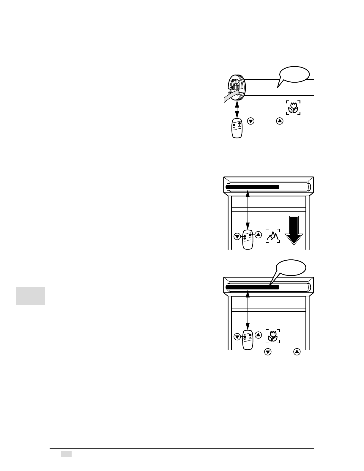
Adjusting the Lower End Position
I
The lower end position must be
adjusted first.
From far range, press the up or down button and
hold until the installation has reached the desired
end position.
Corrections are possible with the up and down
buttons.
Saving the lower end position:
From close range, press the up or down button
and hold approx. 1 second, then release.
The motor responds (1 x ‘Click-Click’).
max. 15 cm
clickclick
or
approx. 1 sec.
1 x
min.
1,5 m
clickclick
1 x
max.
15 cm
or
approx. 1 sec.
9
www.geiger.de
EN
EN
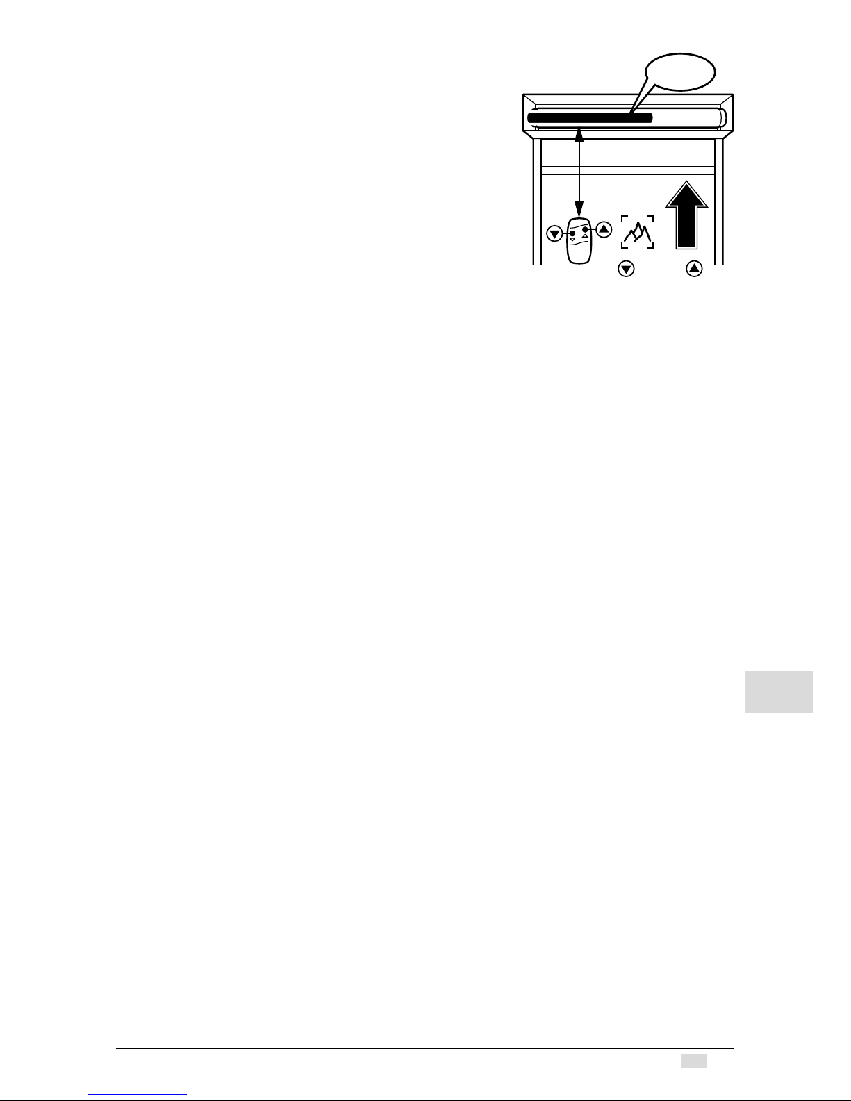
Adjusting the Upper End Position
From far range, press the up or down button
and hold approx. 3 seconds until the installation
retracts and locks.
As soon as the upper end position is reached,
the motor automatically turns off and the upper
end position is saved. You will hear the motor (1 x
‘Click-Click‘). The up and down buttons are now
assigned to the corresponding turning direction of
the motors!
The learning mode is now concluded.
I
Finally, conduct at least one trial run,
so that the motor electronics can
automatically detect the threshold of the torque disconnection.
9.
Side awnings operation
After the tensioning of the cloth on the outer end position retract the awning until
the motor disconnects via torque recognition.
A perfect tensioning of the cloth is thus ensured.
10.
GEIGER-Powertronic
The GEIGER-Powertronic enables the user to change the motor’s closing characteristics. The user can raise or reduce the closing power applied through the motor.
This way, he or she influences the closing characteristics of the casing. A rise in the
closing power causes a tighter closing of the casing with increased stress on the
fabric; a reduction in the closing power causes a looser closing and less strain to
the fabric.
Closing power levels: from level 0 to level 7
GEIGER-delivery setting: level 0
I
Caution: By manually raising the closing power (e.g. from level 0 to
level 7) the fabric endures more strain.
In which situations is the GEIGER-Powertronic applied?
• If the closing operation should be optimised for better fabric protection.
When can the GEIGER-Powertronic be applied?
• Anytime; this function can be activated during initial operation, as well as at a
later date.
Which resources are necessary?
• GEIGER-hand-held remote, which is taught-in in accordance with Chapter 7
(page 7).
Please note:
• The end positions are not affected when the GEIGER-Powertronic is activated.
• Only activate the GEIGER-Powertronic after the end positions have been taughtin and a complete trial has been conducted.
clickclick
1 x
min.
1,5 m
or
approx.3 sec.

10
Gerhard Geiger GmbH & Co. KG | 100W0595 0818V001
en
EN
EN
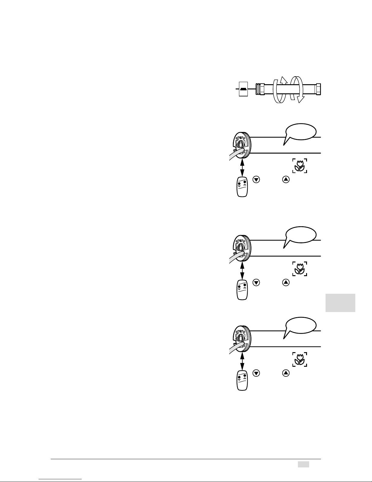
Activating the GEIGER-Powertronic:
1. At close range, press the ‘Up’ or ‘Down’ button
and hold approx. 3 seconds until you hear the
motor (1 x ‘Click-Click‘).
2. From far range, press the ‘Up’ or ‘Down’ button
and hold approx. 1 second until you hear the
motor (1 x ‘Click-Click‘).
3. At close range, press the ‘Up’ or ‘Down’ button
and hold approx. 3 seconds until you hear the
motor (1 x ‘Click-Click‘).
Now the power can be incrementally increased
with the ‘Up’ button and incrementally reduced
with the ‘Down’ button.
4. When the desired power level is reached, at
close range, press the ‘Up’ or ‘Down’ button
and hold approx. 1 second. The motor is now in
its normal operating mode. (1 x ‘Click-Click‘).
The learning mode is now concluded.
I
As soon as the lowest or highest power
level has been reached and you try to
continue to raise or lower the level, you
will hear a signal from the motor (2 x
‘Click-Click‘).
Should there be no activity for 60 seconds,
learning mode will be deactivated. The power level
set will be assumed!
clickclick
1 x
max.
15 cm
or
approx. 3 sec.
clickclick
1 x
min.
1,5 m
or
approx. 1 sec.
clickclick
1 x
max.
15 cm
or
approx. 3 sec.
clickclick
1 x
max.
15 cm
or
approx. 1 sec.
11
www.geiger.de
EN
EN
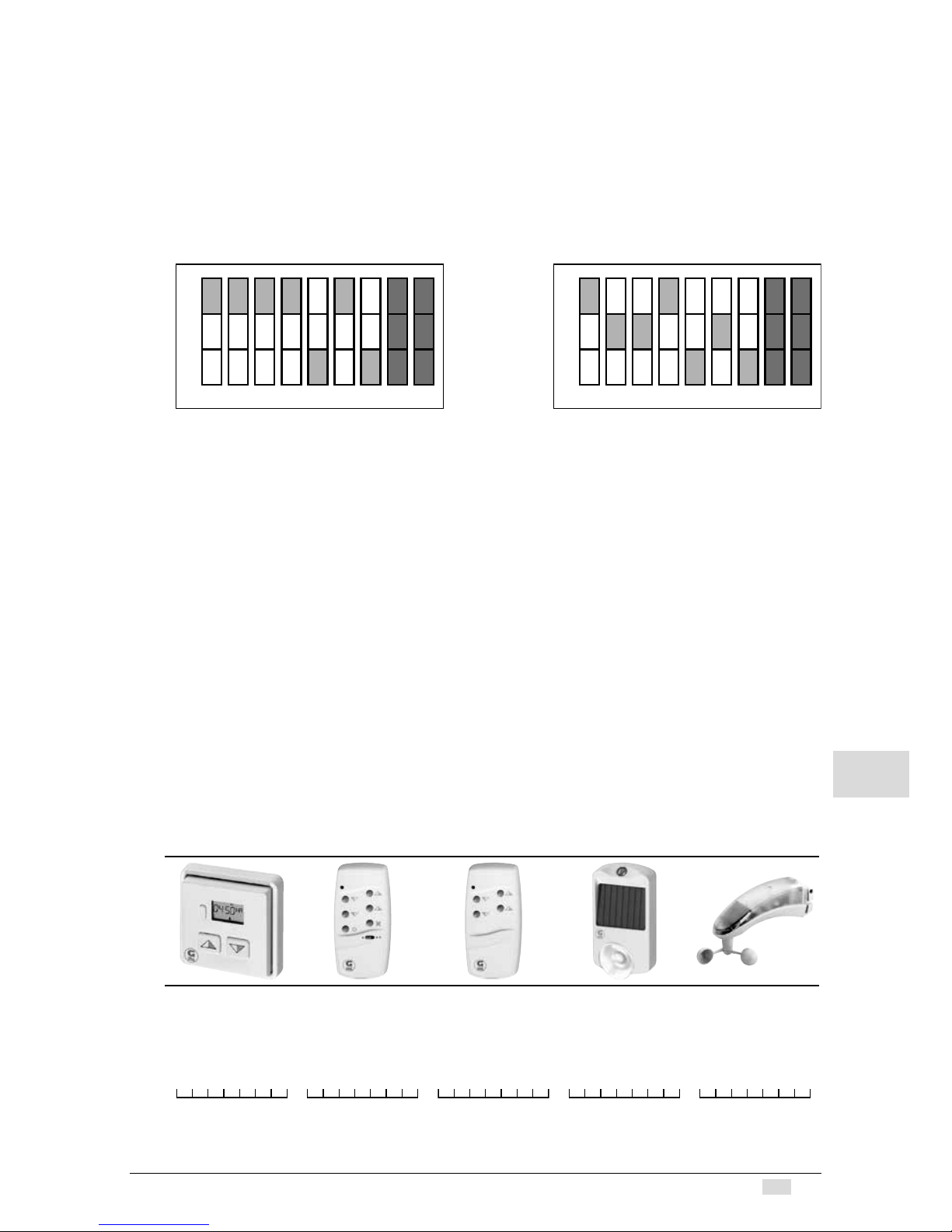
11.
Function description of radio motor
In the delivery state, each GEIGER radio receiver and radio transmitter is equipped
with the “GEIGER-Code“ + + + + - + - so that the motor can be operated
immediately, in order, for example, to facilitate the installation of hangings on the
winding shaft.
I
For security reasons, the „GEIGER-Code“ must be overwritten by an
individual code! This takes place automatically in the teaching for the
first time of an individual code (see page 6 learn/delete radio codes).
„GEIGER code“ individual code (example)
The DIP switches No. 8 and No. 9 have no function!
Please take the description and adjustments from the operating instructions of the
appropriate hand-held/wall transmitter.
12.
Radio codes
A maximum of three different functional codes can be taught. The motor can thus be
a member in three groups that are independent of one another. Additionally, a further
two radio sensor codes can be taught.
If three radio codes have already been taught and it is attempted to teach a fourth
code, the radio code learnt as the third code is cancelled and replaced by the new
code. If two radio sensor codes have already been taught and it is attempted to
teach a third code, the radio sensor code learnt as the second code is cancelled and
replaced by the new code.
Example:
Wireless receiver in the motor
Group 1
Code
+ o o + - o -
Group 2
Code
+ + + o o + +
Group 3
Code
+ - + + - + +
Sensor 1
Code
+ - + + - + +
Sensor 2
Code
+ + + - - + +
For your documentation record any hand-held remote/sensor codes taught
into the motor here:
Group 1 Group 2 Group 3 Sensor 1 Sensor 2
+
0
-
2 3 4 5 6 7 8
+
0
-
2 3 4 5 6 7 8

12
Gerhard Geiger GmbH & Co. KG | 100W0595 0818V001
en
EN
EN
Programming in the far range/near range
In the radio receiver of the motor is integrated an approach detector that
recognizes whether a radio transmitter is operated from some distance = far range,
(at least 1.5 metres distance to the motor control or 0.5 metres to the motor cable),
or it is operated close to the antenna = near range, (at most 15 cm removed or
directly on the motor connecting cable).
I
Caution: If radio receivers or motor connecting cables lie near to
one another, unintentional codes can be transmitted to other radio
receivers.
Recommendation:
When starting the motor for the first time, disconnect motors that are intended to
be operated by another pair of keys, or by another code, from the mains.
13.
Obstacle recognition
When, after the teaching of the first complete, uninterrupted travel from one end
position to the other end position is carried out, the torque needed is learnt.
In any following complete, uninterrupted travel from end position to end position,
the torque needed is automatically reset. Slow changes in the installation due to
ageing, soiling, cold or heat are thus automatically taken into consideration.
If a travel movement in UP or DOWN direction is blocked by an obstacle, the
motor switches off and a small return motion takes place (no return motion with the
SoftWireless-55).
The running direction in which the obstacle was recognized is blocked.
The block is removed if the motor has been operated in the opposite direction for
a certain time. An obstacle must thus first be released before the motor can be
operated again in the direction of the obstacle.
I
Because of the motor sensitive obstacle detection, the correct
dimensioning of the torque for the respective installation size is
essential.
In the following table please find a selection aid to find out the right motor size:
These are estimated values so please check the correct functioning of the
installation.
1 2 3 4 5 6 8 10 12 15 20 25 30
0,2 0,5 0,7 1,0 1,2 1,5 2,0 2,5 2,9 3,7 4,9 6,1 7,4
0,3 0,5 0,8 1,1 1,3 1,6 2,2 2,7 3,2 4,0 5,4 6,7 8,1
0,3 0,6 0,9 1,2 1,5 1,8 2,4 2,9 3,5 4,4 5,9 7,4 8,8
0,3 0,6 1,0 1,3 1,6 1,9 2,6 3,2 3,8 4,8 6,4 8,0 9,6
0,3 0,7 1,0 1,4 1,7 2,1 2,7 3,4 4,1 5,2 6,9 8,6 10,3
0,4 0,7 1,1 1,5 1,8 2,2 2,9 3,7 4,4 5,5 7,4 9,2 11,0
0,4 0,8 1,2 1,6 2,0 2,4 3,1 3,9 4,7 5,9 7,8 9,8 11,8
0,4 0,8 1,3 1,7 2,1 2,5 3,3 4,2 5,0 6,3 8,3 10,4 12,5
0,4 0,9 1,3 1,8 2,2 2,6 3,5 4,4 5,3 6,6 8,8 11,0 13,2
0,5 0,9 1,4 1,9 2,3 2,8 3,7 4,7 5,6 7,0 9,3 11,6 14,0
0,5 1,0 1,5 2,0 2,5 2,9 3,9 4,9 5,9 7,4 9,8 12,3 14,7
0,5 1,1 1,6 2,2 2,7 3,2 4,3 5,4 6,5 8,1 10,8 13,5 16,2
Weight of bottom bar [kg]
3 Nm 6 Nm 9 Nm 12 Nm
Winding diameter [mm]
50
55
60
65
70
75
80
85
90
95
100
110

13
www.geiger.de
EN
EN
I
When using a wind sensor (GF0024/GF0025) the correct functioning of
the retract command under wind load should be checked by the manufacturer of the sun protection before commissioning.
14.
End position correction
If a lengthening/shortening of the hanging has resulted due to e.g. temperature
changes, this will be automatically corrected by closing the awning.
If, due to temperature changes, an adjusted sleeve performance is set and the
hanging runs against the stop unit, the end position is immediately corrected.
After the first trial, the motor automatically identifies the torque necessary to close
the awning and closes it with the lowest possible power, so that the fabric is
optimally protected.
15.
Technical data
Technical data of short motor SOLIDline-KS (GU45..)
GU4503/55 GU4506/55 GU4509/55 GU4512/55
Voltage
230 V~/50 Hz 230 V~/50 Hz 230 V~/50 Hz 230 V~/50 Hz
Current
0,47 A 0,63 A 0,8 A 1,0 A
Cos Phi (cosj)
>0,95 >0,95 >0,95 >0,95
Inrush current
(factor)
x 1,2 x 1,2 x 1,2 x 1,2
Power
105 W 140 W 180 W 220 W
Torque
3 Nm 6 Nm 9 Nm 12 Nm
Speed of rotation
55 1/min 55 1/min 55 1/min 55 1/min
Protection type
IP 44 IP 44 IP 44 IP 44
Total length
1)
515,5 mm 545,5 mm 565,5 mm 585,5 mm
Operating type
S2 4 min S2 5 min S2 4 min S2 4 min
Diameter
45 mm 45 mm 45 mm 45 mm
Weight
approx.
1,9 kg
approx.
2,2 kg
approx.
2,4 kg
approx.
2,7 kg
1)
SOLIDline-ZN +1 mm / SOLIDline-COM/-SIC + 4,5 mm / SOLIDline-SOC: + 4 mm
Subject to technical modifications
16.
Notes on waste disposal
Recycling of packaging materials
In the interest of environmental protection, please contact your local government’s
recycling or solid waste management department to learn more about the services it
provides.
Waste disposal of electric and electronic equipment
Electronic equipment or batteries cannot be discarded along with the normal
household waste. Keep for more information on the recycling and disposal
methods envisaged by the local regulations in your area.

14
Gerhard Geiger GmbH & Co. KG | 100W0595 0818V001
en
EN
EN
17.
Information for the specialist electrician
H
Caution:
Wrong installation and wrong connection
can lead to serious injuries.
The parallel operation of the several SOLIDline
SoftZeroWireless-55/SOLIDline SoftWireless-55
is possible.
PVC cables are not suitable for equipment used
outdoors or exposed to prolonged high levels of
UV radiation.
These cables should not be used if they are likely
to touch metal parts that can heat up to temperatures exceeding 100°C.
Connecting cables with plug connectors of the
Hirschmann Company, type STAS 3K or the
Phoenix Mecano Company, type GLS/3+PE may
only be used in connection with the Hirschmann
cable socket STAK 3K.
18.
Declaration of conformity
We herewith explicitly declare that this product complies with the essential requirements and relevant directives. It is authorised for use in all EC member states and
in Switzerland without any need of prior registration. The Declaration of Conformity
concerning this product is available on our website: www.geiger-antriebstechnik.de.
Electronic
limit stop
+
radio receiver
1
blue
brown
black
green/yellow
23
PE NL1
L1
N
PE
Mains 230V / 50Hz
15
www.geiger.de
EN
EN
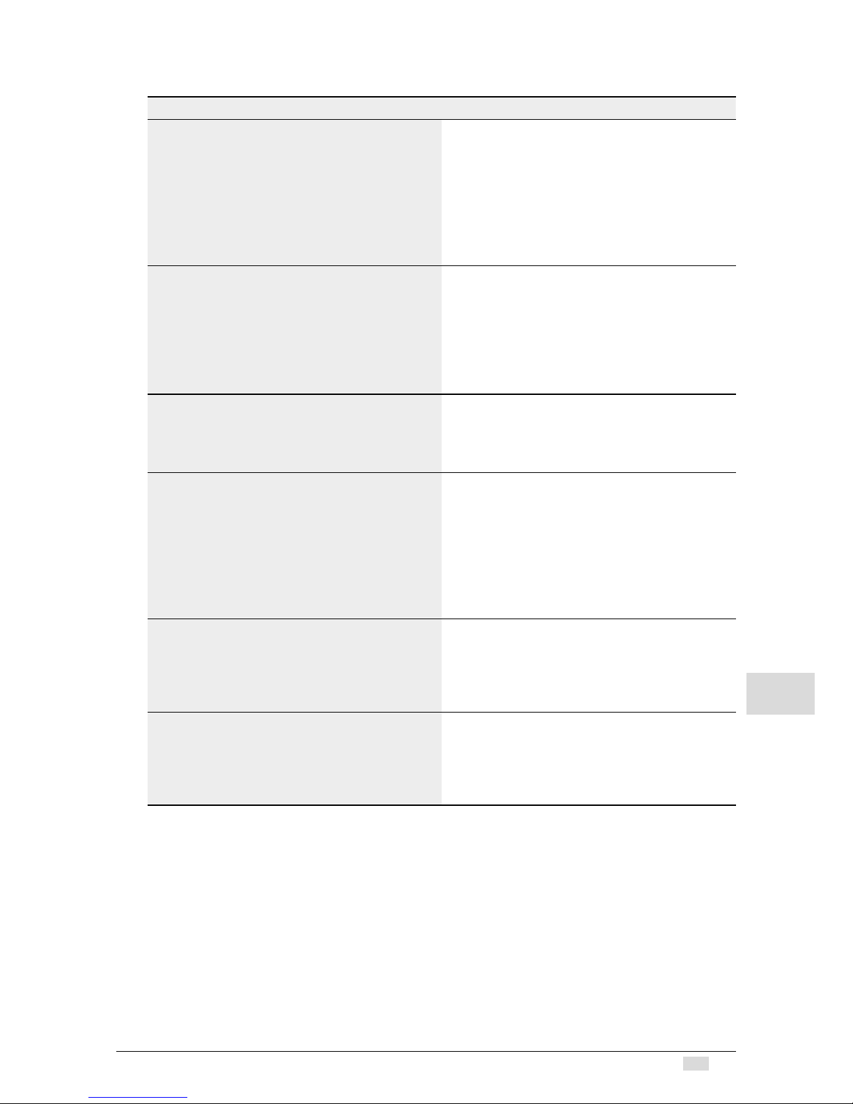
19.
What to do if…
Problem Solution
No short “click-click“
on switching on the motor.
• Motor not plugged in.
Please check the plug connection.
Check connecting cable for possible
damage.
• Check the mains voltage and allow
the cause of the voltage breakdown
to be tested by a specialist electrician.
Hand-held transmitter
does not work.
• Check the battery.
• The wind sensor has triggered. Try
it again after the expiry of the wind
cut-off time.
• Inadvertent deletion of the radio code.
Start learning radio code again (see
page 7).
After running several times,
the motor breaks down and
no longer responds.
• The motor became too hot and has
switched off.
Try it again after a cooling time of
about 15 min.
The motor no longer
runs automatically.
• The sun automatic control mechanism was switched off.
• The wind sensor has triggered.
Try it again after the expiry of the wind
cut-off time.
• Inadvertent deletion of the radio
code. Start learning radio code again
(see page 7).
The motor does not react to the near
range
• Move as close as possible to the
motor head with the hand-held
transmitter.
• Exchange the batteries in the handheld transmitter.
The motor stops between the upper
and the lower end stop.
• The motor has detected an obstacle.
Please remove the obstacle. The
device will be unlocked if the motor
is run for a short time period in the
opposite direction.

16
Gerhard Geiger GmbH & Co. KG | 100W0595 0818V001
en
EN
EN
For technical questions, please call our service team at: +49 (0) 7142 938-333.
They will be happy to assist you.
Gerhard Geiger GmbH & Co. KG
Schleifmühle 6
D-74321 Bietigheim-Bissingen
Telephone: +49 (0) 7142 938-0
Telefax: +49 (0) 7142 938-230
E-Mail: info@geiger.de
Internet: www.geiger.de
 Loading...