

Gehl SL7600, SL7800 Operator's Manual
SL7600
SL7800
SKID STEER
LOADER
Form No.
908274
English
OPERATOR’S MANUAL
®

Gehl Company, in cooperation
with the American Society of
Agricultural Engineers and the
Society of Automotive Engineers, has
adopted this Safety Alert Symbol to
pinpoint precautions which, if not
properly followed, can create a safety
hazard. When you see this symbol in
this manual or on the machine itself,
you are reminded to BE ALERT! Your
personal safety is involved!
Operators must have instructions
before running the machine.
Untrained operators can cause
injury or death.
CORRECT
WRONG
Never use loader
without ROPS/FOPS.
Never modify the
ROPS/FOPS structure.
WRONG
Read Operator's Manual
before using machine.
CORRECT
Always fasten seatbelt
snugly. Always keep feet
on the floor/pedals when
operating loader.
Never use the loader to
lift personnel.
WRONG
Do not use loader around
explosive dust or gas, or
where exhaust can contact
flammable material.

SL7600 and SL7800 Skid Steer Loader
Operator’s Manual
TABLE OF CONTENTS
Introduction .........................1
Safety ...........................5
Controls And Safety Equipment..............15
Operation .........................34
Service ..........................45
Troubleshooting ......................63
Maintenance Schedule ..................71
Specifications .......................75
Index ...........................81
Torque Specifications ...................83
Warranty .........................84
Loader Model Number
Loader Serial Number
Engine Serial Number
All-Tach, Hydraloc and Hydraglide are trademarks of Gehl Company.
Gehl and Powerview are registered trademarks of Gehl Company.

INTRODUCTION
This Operator’s Manual gives the owner/operator information about
maintaining and servicing SL7600 and SL7800 skid steer loader models.
More importantly, this manual provides anoperating plan for safe and proper
use of the machine. Major points of safe operation are detailed in the Safety
chapter of this manual.
We ask that you read and understand the contents of this manual completely
and become familiar with your new machine before operating it. See your
authorized Gehl dealer if you have any questions concerning information in
the manual, require extra manuals or for information concerning the
availability of manuals in other languages.
Throughout this manual, information is provided set in italic type and
introduced by the word Note or Important. Read carefully and comply with
the message — it will improve your operating and maintenance efficiency,
help avoid breakdowns and damage, and extend your machine’s life.
A manual storage box in the operator’s compartment holds the Operator’s
Manual and AEM Safety Manual. Please return the manuals to this box and
keep them with the unit at all times. If this machine is resold, we recommend
that these manuals be given to the new owner.
The attachments and equipment available for use with this machine have a
wide variety of potential applications. Read the manual provided with the
attachment to learn how to safely maintain and operate the equipment. Be
sure the machineis suitably equipped for thetype of workto be performed.
Do not use this machine for any applications or purposes other than those
described in this manual or applicable for approved attachments. If the
machine is to be used with special attachments or equipment other thanthose
approved by Gehl Company, consult your Gehl dealer. Any person using
non-approved attachments or making unauthorized modifications is
responsible for the consequences.
The Gehl dealership network stands ready to provide you with any assistance
you may require, including providing genuine Gehl service parts. All service
parts should be obtained from your Gehl dealer. Give complete information
about the part and include the model and serial numbers of your machine.
Record these numbersin the spaceprovided on theTable of Contentspage, as
a handy reference.
Please be aware that Gehl strives to continuously improve its products and
reserves the right to make changes and improvements in the design and
construction of any part without incurring the obligation to install such
changes on any unit previously delivered.
1 908274/BP1202

If this machine was purchased "used," or if the owner's address has changed,
please provide your Gehl dealer or Gehl Company Service Department with
the owner's name and current address, along with the machine model and
serial number. This will allow the registered owner information to be
updated, so that the owner can be notified directly in case of an important
product issue, such as a safety update program.
908274/BP1202 2
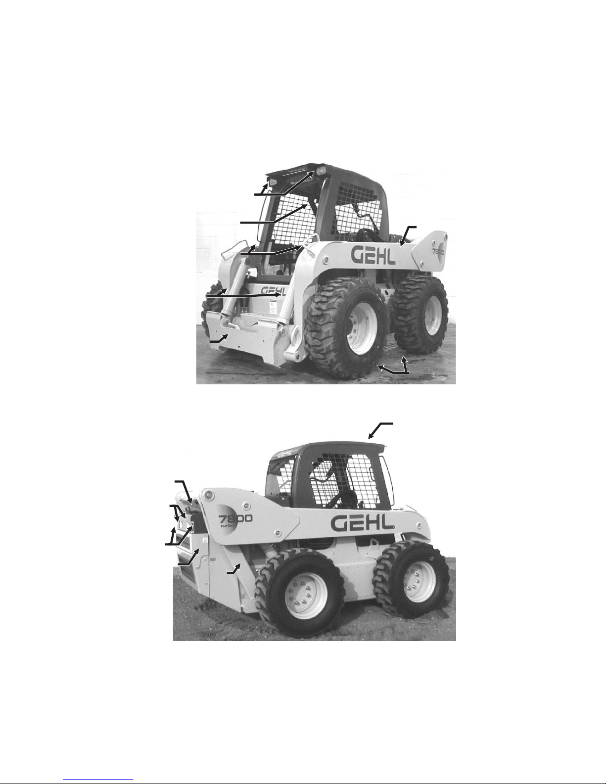
Model Identification
Front Work Lights
Engine
Cover
Rear Work
Lights
Restraint Bar
Hand Holds
Tilt
Cylinders
Hitch
Lift Arm
Tires
Roll Over/
Falling Object
Protective
Structure
(ROPS/FOPS)
Tail Lights
Rear Door
3 908274/BP1202
Rear Link
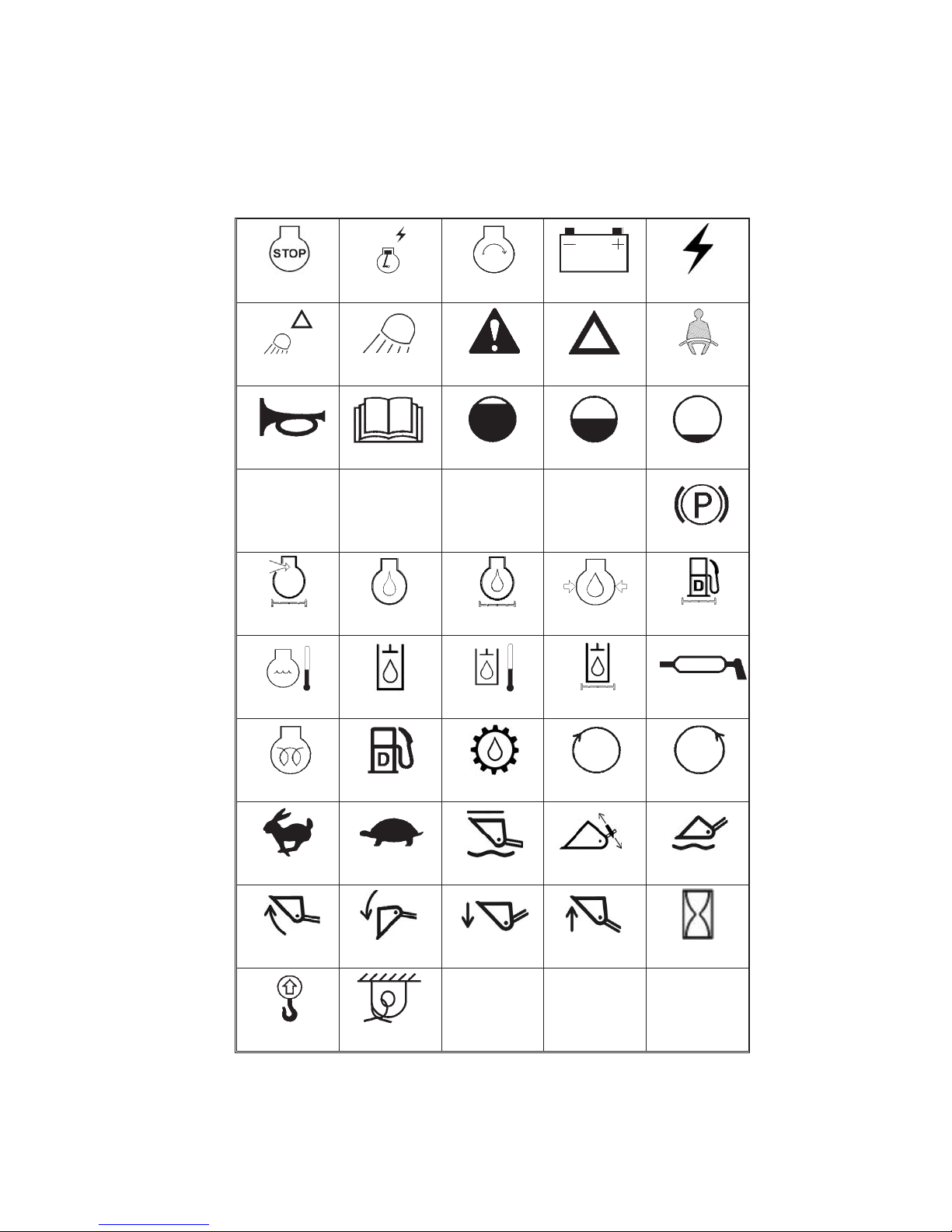
Control/Indicator Symbols
Worklight
w/Flasher
Horn
H-L
High - Low
Engine Air Filter
Engine Coolant
Temperature
Worklight
Read Operator’s
Manual
N
Neutral
Engine Oil
Hydraulic System
Engine StartPower Off Power On
Safety Alert
Volume - Full
F
Forward
Engine Oil Filter Fuel Filter
Hydraulic Oil
Temperature
Battery Charge
Hazard Flasher
Volume- Half Full Volume - Empty
Electrical Power
Seatbelt - Lap
Only
R
Reverse
Engine Oil
Pressure
Hydraulic Oil
Filter
Parking Brake
Grease
Lubrication Point
Pre-Heat
Fast
Bucket - Rollback Bucket - Dump
Lift Point
908274/BP1202 4
Diesel Fuel
Slow
Tie-Down
Chaincase Oil
Bucket - Lower
Clockwise
Rotation
Power HitchRide Control
Bucket - Raise
Counterclockwise
Rotation
Bucket - Float
Service Hours

SAFETY
This safety alertsymbol means Attention! Become alert!Your safety
is involved! It stresses an attitude of “Heads Up for Safety” and can
be found throughout this Operator’s Manual and on the decals on the
machine.
Before operating this machine, read and study the following safety
information. In addition, be sure that everyone who operates or works with
this machine, whether family member or employee, is familiar with these
safety precautions. It is essential to have competent and careful operators,
who are not physically or mentally impaired, and who are thoroughly trained
in the safe operation of the machine and the handling of loads. It is
recommended that the operator be capable of obtaining a valid motor vehicle
operator’s license.
The use of skid steer loaders is subject to certain hazards that cannot be
eliminated by mechanical means, but only by exercising intelligence, care
and common sense. Such hazards include, but are not limited to, hillside
operation, overloading, instability of the load, poor maintenance and using
the equipment for a purpose for which it is not intended or designed.
Gehl
ALWAYS considers the operator’s safety when designing its machinery
and guards exposed moving parts for the operator’s protection. However,
some areas cannot beguarded or shielded in order to assure proper operation.
Furthermore, this Operator’s Manual and the decals on the machine warn of
additional hazards and they should be read and observed closely.
Some photographs in this manual may show doors, guards and shields open
or removed for illustrative purposes only. Be sure that all doors, guards and
shields are in their proper operating positions before starting the engine to
operate the unit.
Different applications may require optional safety equipment, such as a
back-up alarm, horn, mirror, strobe light or an impact-resistantfront door. Be
sure you know the job site hazards and equip your machine as needed.
DANGER
situation which, ifnot avoided, willresult indeath orserious injury.
WARNING
situation which, if not avoided, could result in death or serious
injury.
CAUTION
situation which, if not avoided may result in minor or moderate
injury. May also alert against unsafe practices.
5 908274/BP1202
“DANGER” indicates an imminently hazardous
“WARNING” indicates a potentially hazardous
“CAUTION” indicates a potentially hazardous

Mandatory Safety Shutdown Procedure
Before cleaning, adjusting, lubricating, servicing the unit or leaving it
unattended:
1. Move the drive control handle(s) to the neutral position.
2. Lower the lift arm and attachment completely. If the lift arm must be left
in the raised position,
BE SURE to properly engage the lift arm support
device (page 17).
3. Move the throttle to the low idle position, shut off the engine and remove
the key.
4. Before exiting, move the lift/tilt control(s) to verify that the controls do
not cause movement of the lift arm and hitch.
Safety Reminders
Before Starting
Ü Do not modify the ROPS/FOPS unless instructed to do so in installation
instructions. Modifications such as welding, drillingor cutting can weaken
the structure and reduce the protection it provides. A damaged
ROPS/FOPS cannot be repaired — it must be replaced.
Ü To ensure safe operation, replace damaged or worn-out parts with genuine
Gehl service parts.
Ü Gehl skid steer loaders are designed and intended to be used onlywith Gehl
attachments or approved referral attachments. Gehl cannot be responsible
for operator safety if the loader is used with a non-approved attachment.
Ü Remove all trash and debris from the machine each day, especially in the
engine compartment, to minimize the risk of fire.
Ü
Always face the loader and use the hand holds and steps when getting on
and off the loader. Do not jump off the loader.
Ü
Never use starting fluid (ether).
Ü
Walk around the machine and warn allnearby personnel before starting the
machine.
Ü
Always perform a daily inspection of the machine before using it. Look for
damage, loose or missing parts, leaks, etc.
During Operation
Ü
Machine stability is affected by: the load being carried, the height of the
load, machine speed, abrupt control movements and driving over uneven
terrain.
LOADER TO TIP, THROWING THE OPERATOR OUT OF THE SEAT OR
LOADER, RESULTING IN DEATH OR SERIOUS INJURY.
ALWAYS operate with the seatbelt fastened and the restraint bar lowered.
DISREGARDING ANY OF THESE FACTORS CAN CAUSE THE
Therefore,
Do not exceed the machine’s Rated Operating Load. Carry the load low.
Move the controls smoothly and gradually, and operate at speeds
appropriate for the conditions.
908274/BP1202 6

Always travel with the heavier end of the loader toward the top of the
Ü
incline for additional stability when operating on inclines or ramps.
Do not raise or drop a loaded bucket or fork suddenly. Abrupt movements
Ü
under load can cause serious instability.
Never push the lift control into the “float” position with the bucket or
Ü
attachment loaded or raised, because this will cause the lift arm to lower
rapidly.
Do not drive too close to an excavation or ditch; be sure that the
Ü
surrounding ground has adequate strength to support the weight of the
loader and the load.
Never carry riders. Do not allow others to ride on the machine or
Ü
attachments, because they could fall or cause an accident.
Always look to the rear before backing up the skid steer loader.
Ü
Operate the controls only from the operator’s seat.
Ü
Always keep hands and feet inside the operator’s compartment while
Ü
operating the machine.
Ü New operators must operate the loader in an open area away from
bystanders. Practice with the controls until the loader can be operated
safely and efficiently.
Ü Exhaust fumes can kill. Do not operate this machine in an enclosed area
unless there is adequate ventilation.
Ü When you park the machine and before you leave the seat, check the
restraint bar for proper operation. The restraint bar, when raised,
deactivates the lift/tilt controls and auxiliary hydraulics, and applies the
parking brake.
Maintenance
Ü
Never attempt to by-pass the keyswitch to start the engine. Use only the
jump starting proceduredetailed in theOperation chapter ofthis manual.
Ü
Never use your hands to search for hydraulic fluid leaks. Instead, use a
piece of paper or cardboard. Escaping fluid under pressure can be invisible
and can penetrate the skin and cause serious injury. If any fluid is injected
into your skin, see a doctor at once. Injected fluid must be surgically
removed by a doctor or gangrene may result.
Ü
Always wear safety glasses with side shields when striking metal against
metal. In addition, it is recommended that a softer (chip resistant) material
be used to cushion the blow. Failure to heed could lead to serious injury to
the eyes or other parts of the body.
Ü
Do not smoke or have any spark producing equipment in the area while
filling the fuel tank or while working on the fuel or hydraulic systems.
7 908274/BP1202

Potential Hazards
A skid steer loader operator must
ALWAYS be conscious of the working
environment. Operator actions, the environmental conditions and the job at
hand require thefull attention ofthe operator sothat safetyprecautions can be
taken.
ALWAYS maintaina safe distance from electric power lines andavoid contact
with any electrically charged conductor or gas line. Accidental contact or
rupture can result in electrocution or an explosion. Contact the North
American One CallReferral System at(888) 258-0808 forthe local "Digger's
Hotline" number or the proper local authorities for utility line locations
BEFORE starting to dig!
Exposure to crystalline silica (found in sand, soil and rocks) has been
associated with silicosis,a debilitating andoften fatal lung disease. A Hazard
Review (Pub. No. 2002-129) by the U.S. National Institute for Occupational
Safety and Health(NIOSH) indicates a significant risk of chronicsilicosis for
workers exposed to inhaled crystalline silica over a working lifetime.
NIOSH recommends an exposure limit of 0.05 mg/m
3
as a time-weighted
average for up to a 10-hr workday during a 40-hr workweek. NIOSH also
recommends substituting less hazardous materials when feasible, using
respiratory protection and regular medical examinations for exposed
workers.
Safety Decals
The skid steer loader has decals that provide safety information and
precautions around the loader. These decals must be kept legible. If missing
or illegible, they must be replaced promptly. Replacements may be obtained
from your Gehl dealer. New equipment must have all decals specified by the
manufacturer affixed to their proper place.
New Decal Application
Surfaces must be free of dirt, dust, grease and foreign material before
applying the decal. Remove the smaller portion of the decal backing paper
and apply the exposed adhesive to the clean surface, maintaining proper
position and alignment. Peel the rest of the backing paper and apply hand
pressure to smooth out the decal surface. Refer to the following pages for
proper decal location. Text decals begin on page 9; no-text decals begin on
page 12.
908274/BP1202 8
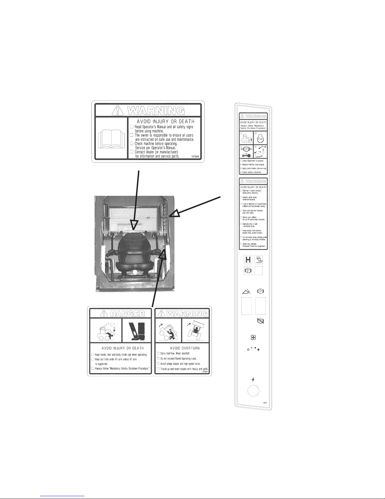
Safety Decals inside the ROPS
137628 - Located on manual box, behind seat
137647 - Located on operator’s lower left side
9 908274/BP1202
Part of left instrument panel
Safety Decals on the Outside of the Skid Loader
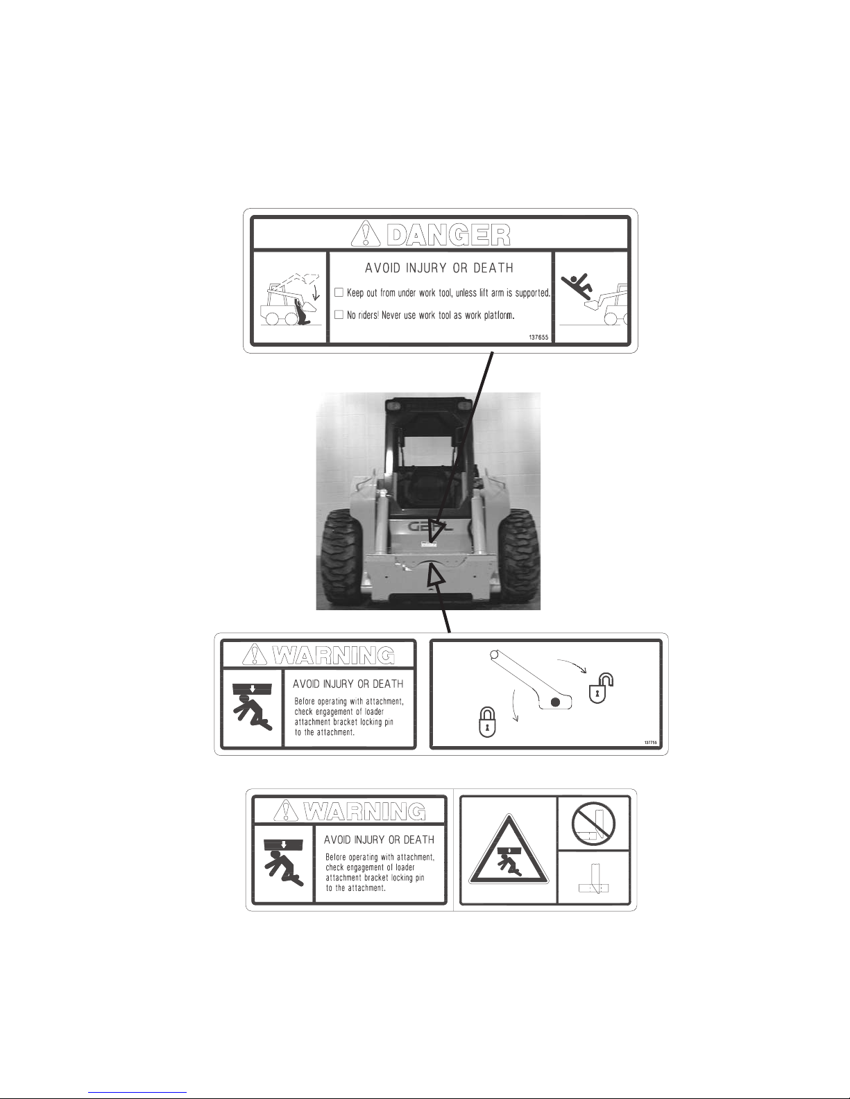
137655 - Located on front of loader
137755 - Located on hitch (manual hitch loaders only)
139101 - Located on hitch (power hitch loaders only)
908274/BP1202 10
Safety Decals in the Engine Compartment
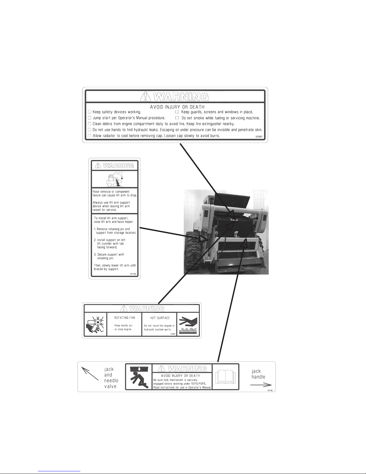
137657 - Located on radiator
137756 - Located on lift arm
support device
137658 - Located on radiator
137760 - Located on rear door
11 908274/BP1202
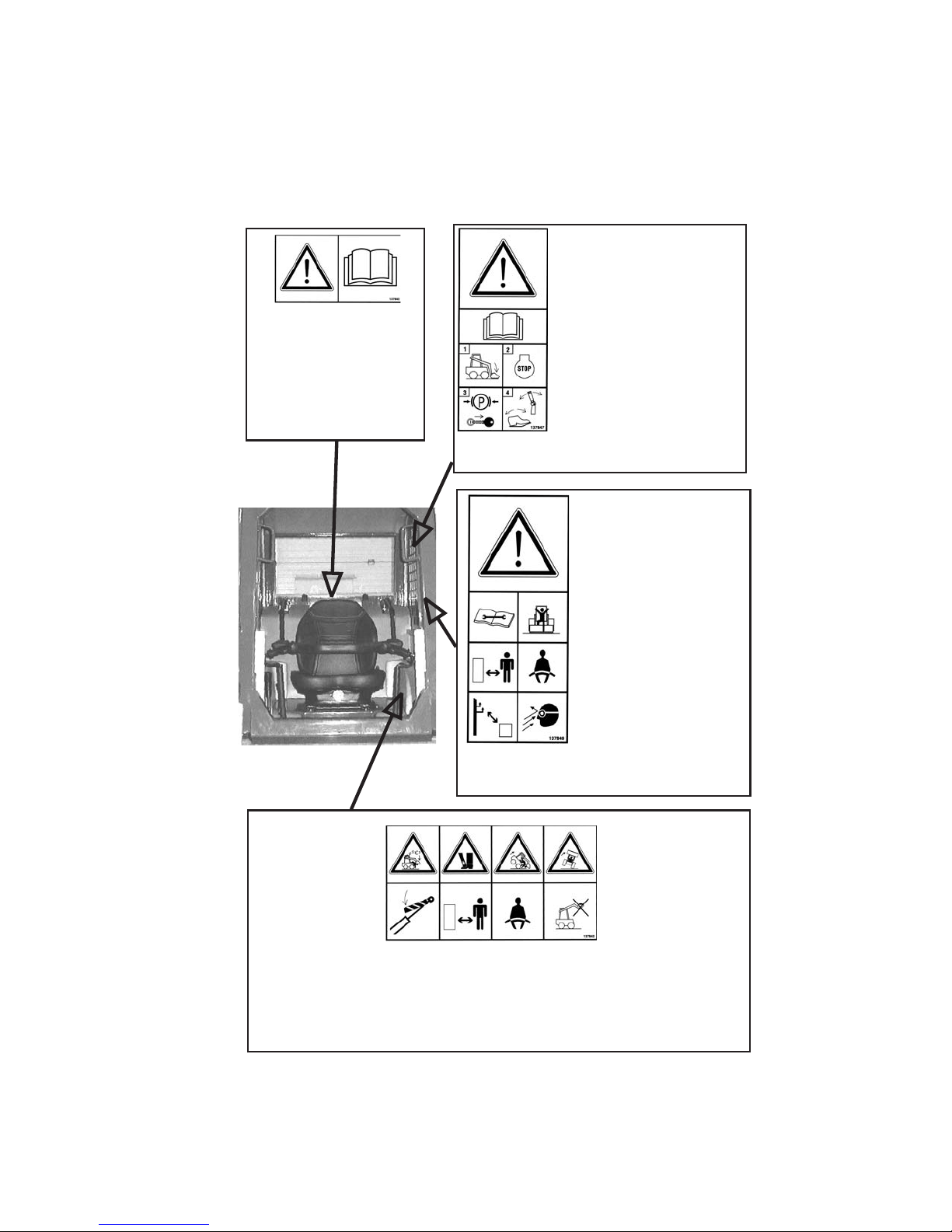
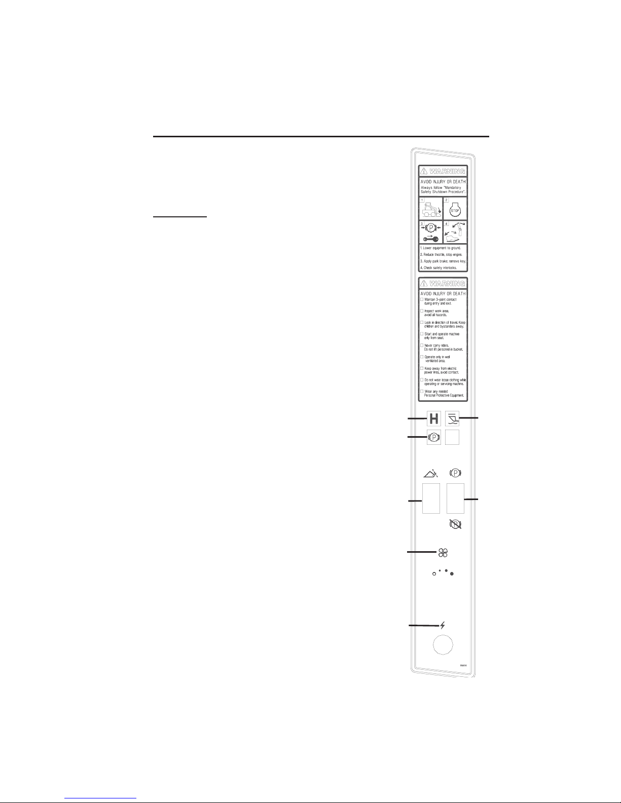
Safety Decals inside the ROPS
137842 - Located on manual
box, behind seat
Safety alert: Read Operator’s
Manual and all safety signs
before using machine. The
owner is responsible to
ensure all users are
instructed on safe use and
maintenance.
Safety alert: Always follow
“Mandatory Safety Shutdown
Procedure” in Operator’s Manual.
1-Lower equipment to ground.
2-Reduce throttle, stop engine.
3-Apply parking brake; remove
key.
4-Check safety interlocks.
137847 – Part of left
instrument panel
A
E
137849 – Part of
left instrument
panel
B
C
D
F
Safety alert:
A-Check machine before
operating; Service per
Operator’s Manual; Contact
dealer (or manufacturer) for
information and service
parts.
B-Maintain 3-point contact
during entry and exit.
C-Inspect work area; Avoid
all hazards; Look in direction
of travel; Keep children and
bystanders away.
D-Start and operate
machine only from seat.
E-Keep away from power
lines; Avoid contact.
F-Wear any needed
Personal Protective
Equipment; Do not wear
loose clothing while
operating or servicing
machine.
137843 - Located on operator’s lower left side
A-Crush hazard: Keep out from under lift arm unless lift arm is supported.
B-Crush hazard: Keep hands, feet and body inside cab when operating.
C-Forward tip hazard: Fasten seat belt; Carry load low; Do not exceed Rated
Operating Load.
D-Side tip hazard: Avoid steep slopes and high speed turns; Travel up and down
slopes with heavy end uphill.
908274/BP1202 12
A
B
C
D
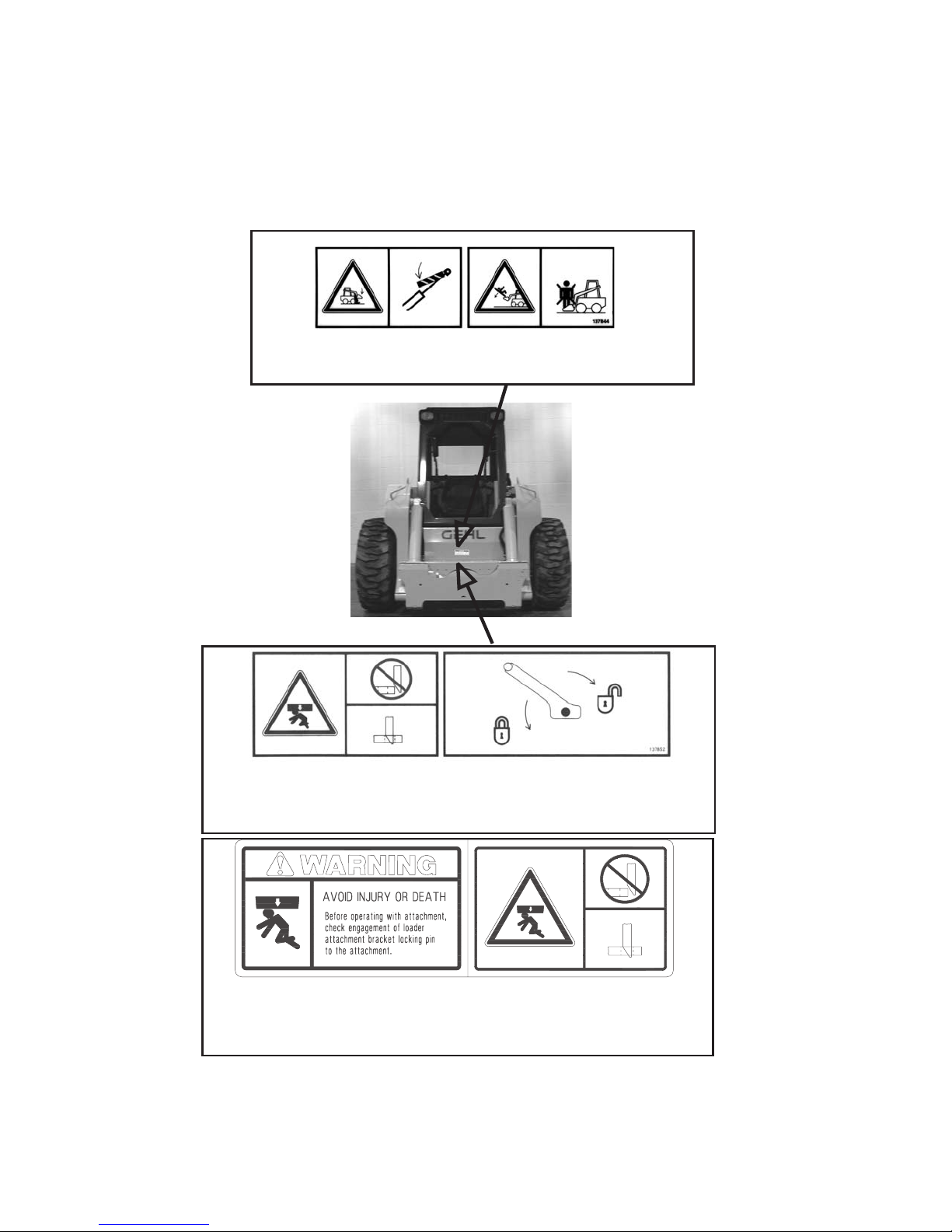
Safety Decals on the Outside of the Skid Loader
A
137844 – Located on front of loader
A-Crush hazard: Keep out from under worktool unless lift arm is supported.
B-Fall hazard: No riders; Never use work tool as work platform.
A
B
B
137852 – Located on hitch (manual hitch loaders only)
Crush hazard: Before operating with attachment, check engagement of hitch locking pin to
the attachment:
A-Incorrect attachment engagement C-Lock hitch lever
B-Correct attachment engagement D-Unlock hitch lever
139101 - Located on hitch (power hitch loaders only)
Crush hazard: Before operating with attachment, check engagement of hitch locking pin to
the attachment:
A-Incorrect attachment engagement
B-Correct attachment engagement
13 908274/BP1202
C
D
A
B
Safety Decals in the Engine Compartment
AB C D E F
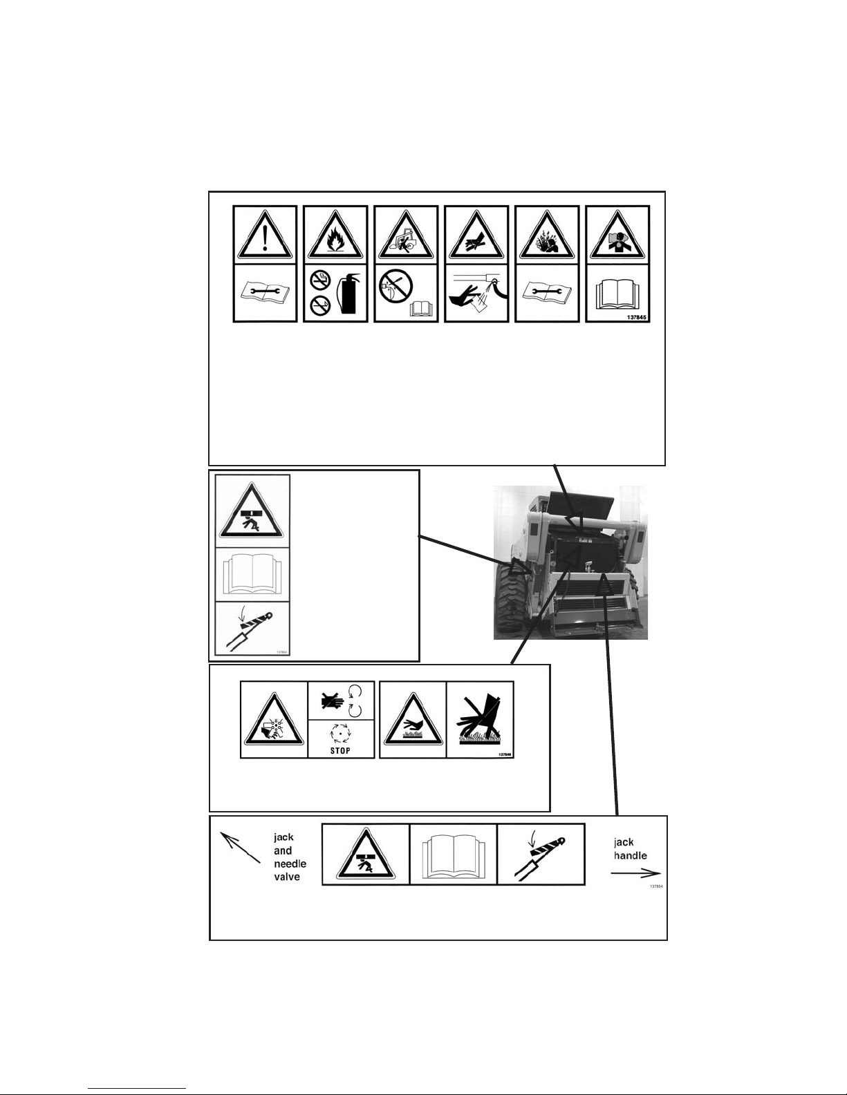
137845 – Located on radiator
A-Safety alert: Keep safety devices in place and in working order; Keep guards,
screens and windows in place.
B-Fire hazard: Do not smoke while fueling or servicing machine; Clean debris from
engine compartment daily to avoid fire; Keep fire extinguisher nearby.
C-Run-over hazard: Jump-start per Operator’s Manual procedure.
D-Oil injection hazard: Do not use hands to find hydraulic leaks; Escaping oil under
pressure can be invisible and penetrate skin; Use a piece of cardboard to find leaks.
E-Burn hazard: Allow radiator to cool before removing cap; Loosen cap slowly to avoid
burns.
F-Suffocation hazard: Operate only in a well-ventilated area.
137853 Located on lift
arm support
device
Crush hazard: Hose
removal or component
failure can cause lift
arm to drop. Always
use lift arm support
device when leaving
lift arm raised for
service.
A
137846 – Located on radiator
A-Rotating fan: Keep hands out or stop engine.
B-Hot surface: Do not touch hot engine or hydraulic system parts.
137854 - Located on rear door
Crush hazard: Be sure lock mechanism is securely engaged before working under
ROPS/FOPS.
908274/BP1202 14
B
CONTROLS and SAFETY EQUIPMENT
CAUTION
Become familiar with and know how to use all
safety devices and controls on the skid steer loader before
operating it. Know how to stop loader operation before starting it.
This Gehl loader is designed and intended to be used only with a
Gehl attachment or a Gehl-approved referral attachment or
accessory. Gehl cannot be responsible for operator safety if the
loader is used with a non-approved attachment.
Guards and Shields
Whenever possible and without affecting loader operation, guards and
shields are provided to protect against potentially hazardous areas. In many
places, safety decals are also provided to warn of potential hazards and/or to
display special operating procedures.
WARNING
Read and thoroughly understand all safety
decals on the loader before operating it. Do not operate the loader
unless all factory-installedguards and shields are properly secured
in place.
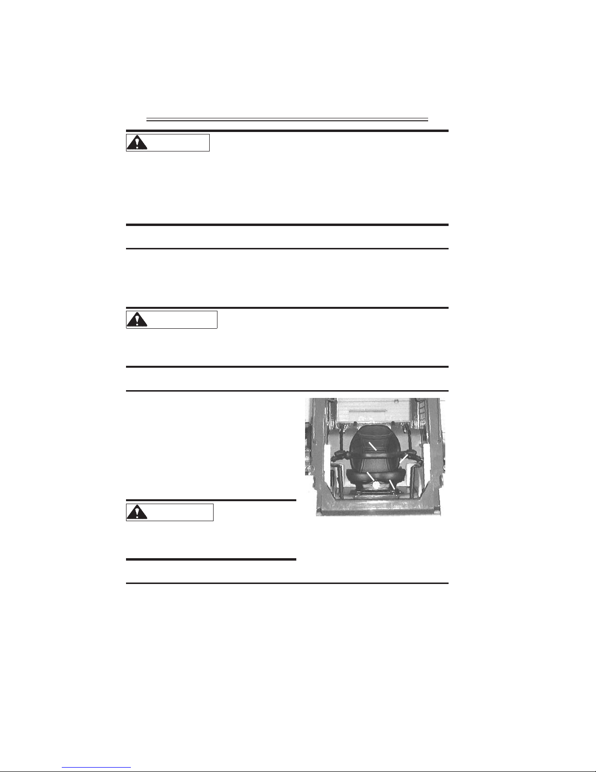
Operator Restraint Bar
Lower the restraint bar after entering the
operator’s compartment. The restraint
bar is securely anchored to the ROPS.
The restraint bar switch and the seat
switch form an interlock for the lift arm,
tilt, drive and starter circuits (refer to the
“Safety Interlock System” topic on
1
2
4
3
page 16 for more information).
WARNING
operator restraint bar or seat
switch electrically or mechanically.
Always wear your seatbelt.
Operator’s Seat
The seat is mounted on rails for backward or forward repositioning. A
spring-loaded latch handle activates the seat adjustment mechanism.
Suspension seat (optional): A weight adjustment knob is provided with this
seat for operator comfort.
15 908274/BP1202
Never defeat the
Fig. 1: Operator’s Seat
1. Restraint Bar
2. Seatbelt
3. Seat Adjustment Lever
4. Suspension Seat Knob
(optional)
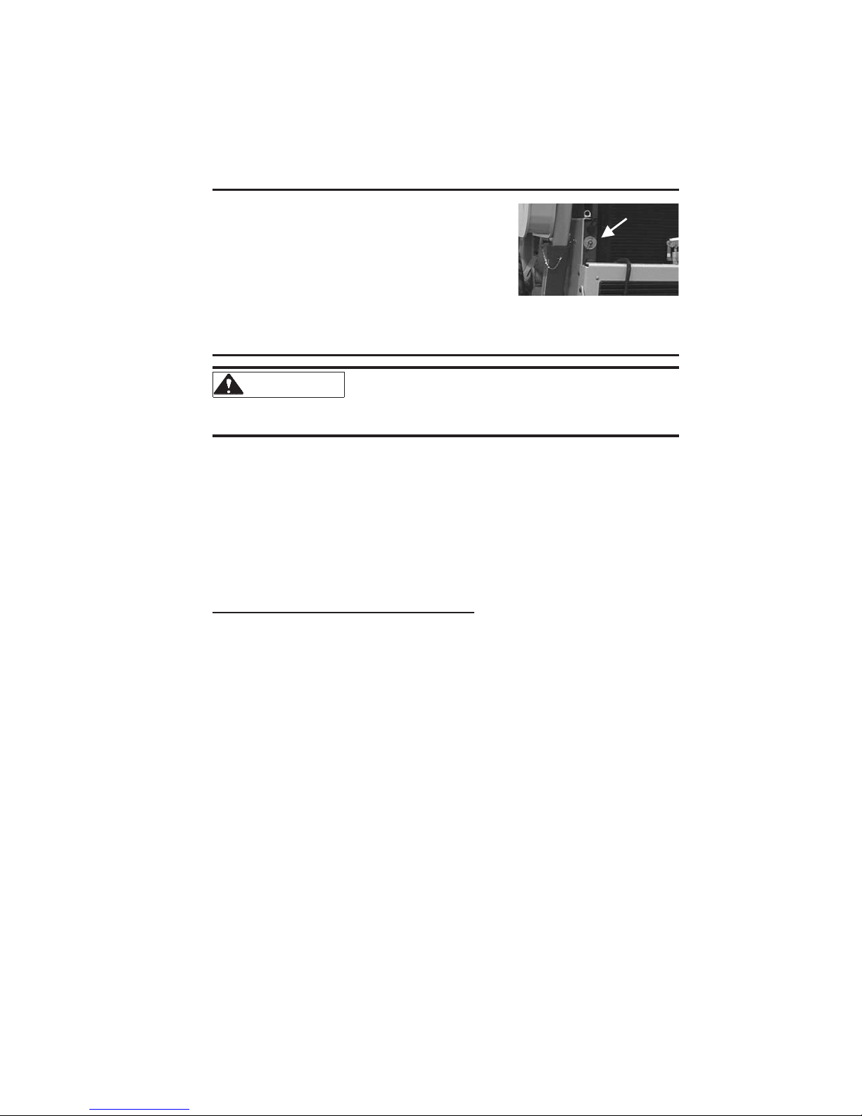
Battery Disconnect
A battery disconnect switch is located in the rear
of the skid loader. Turn the switch to the
OFF
position to disconnect the battery from the
electrical system.
Safety Interlock System
Fig. 2: Battery Disconnect
Switch
WARNING
NEVER defeat the safety interlock system by
mechanically or electrically bypassing any switches, relays or
solenoid valves.
An interlock system is provided on the loader for operator safety. Together
with solenoid valves, switches and relays, the interlock system:
» Prevents the engine from starting unless the operator is sitting on the seat
and the operator restraint bar is down.
» Disables the lift arm, auxiliary hydraulics, attachment tilt and wheel drives
anytime the operatorleaves the seat, turns thekeyswitch to
OFF or raisesthe
restraint bar.
Testing the Safety Interlock System
Before leaving a parked machine, check the safety interlock system for
proper operation:
Restraint Bar
With the engine running, raise the restraint bar. Test each of the controls.
There should be no more than a slight movement of the lift arm, hitch and
machine. If there is any significant movement, troubleshoot and correct
the problem immediately. Contact your dealer if necessary.
Seat Switch
With the engine off and the restraint bar lowered, unfasten your seatbelt.
Lift your weight off the seat. Try to start the engine. If the engine starts,
turn off the engine, and troubleshoot and correct the problem. Contact
your dealer if necessary.
908274/BP1202 16
ROPS/FOPS
The ROPS/FOPS (Roll Over/Falling Object ProtectiveStructure) is designed
to provide protection for the operator from falling objects and in case the
loader tips or rolls over, provided the operator is secured inside the ROPS by
the seatbelt and restraint bar.
WARNING
Never operate the loader with the ROPS
removed or locked back.
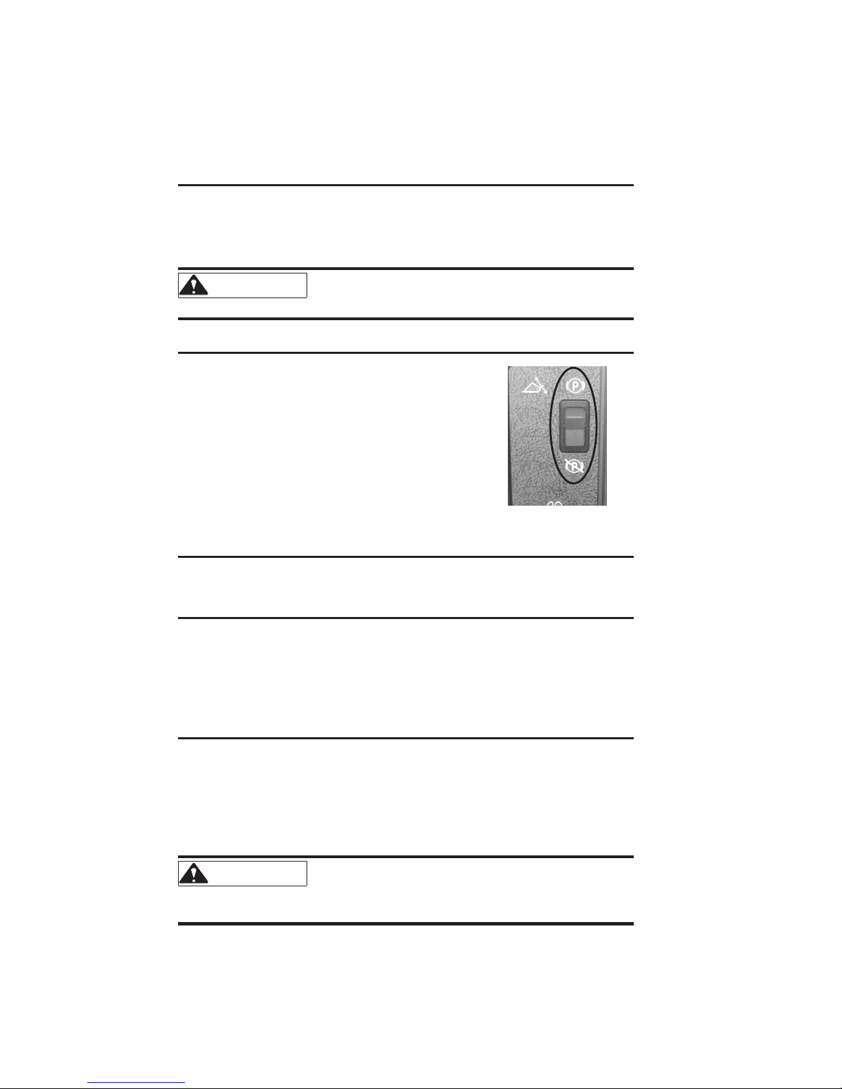
Parking Brake
This skid loader is equipped with a
spring-applied, hydraulic-released parking
brake. The parking brake engages when the
operator lifts the restraint bar, leaves the
operator’s seat or shuts off the engine. The
brake can also be applied manually by using
the switch located on the left control panel of
the ROPS. A red indicator on the left control
panel lights whenthe parking brake is applied.
Fig. 3: Parking Brake Switch
Horn
Pressing the
BLUE button on the left control handle sounds the horn.
Rear Window Emergency Exit
The ROPS rear window has three functions: noise reduction, falling objects
barrier and emergency exit.
To use the emergency exit, unlatch the two latches, push out the window and
exit.
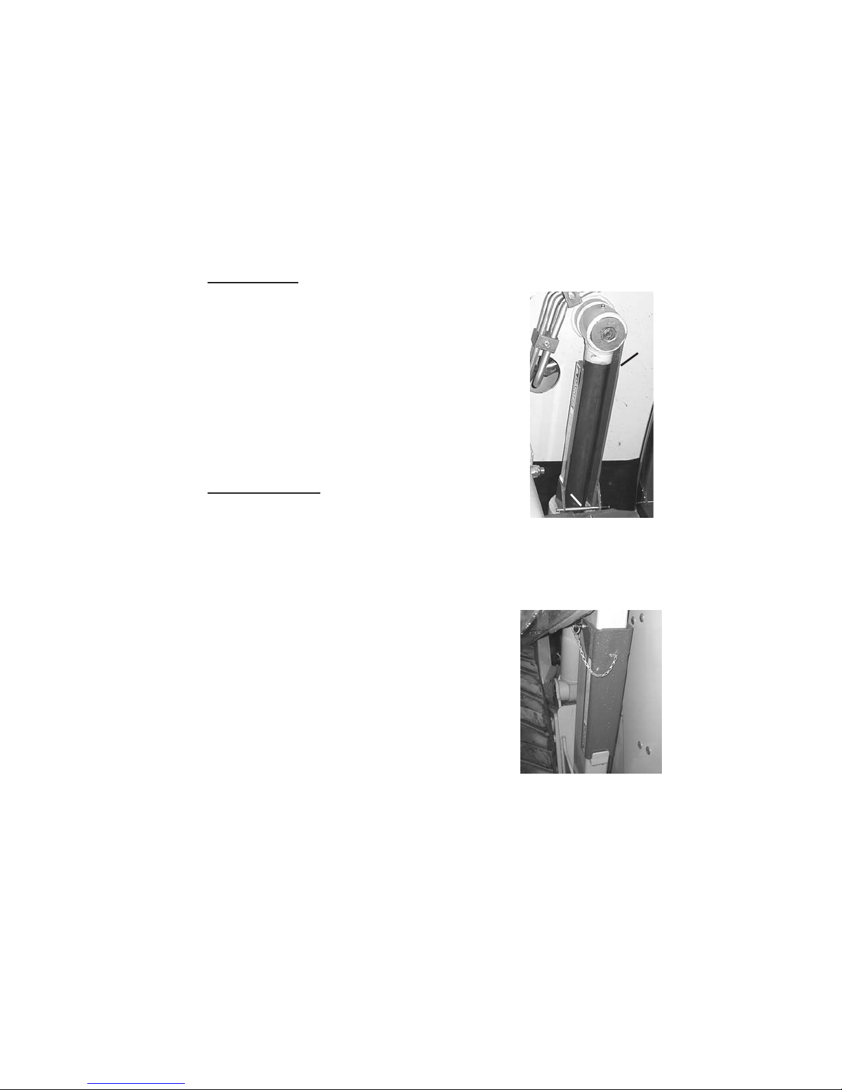
Lift Arm Support Device
The lift arm support device is used as a cylinder lock to prevent the raised lift
arm from unexpectedly lowering. Be sure to engage the support device when
the lift arm is raised for service. When the support device is not being used,
return it to its storage position. The support deviceis a safety device that must
be kept in proper operating condition at all times. The following steps ensure
correct usage:
WARNING
support device requires two people - one person inside the loader
and another person to engage the support device.
17 908274/BP1202
The safest method of engaging the lift arm
Important: With the keyswitch OFF and the solenoid valve functioning
properly, the lift arm will stay raised when the lift control is moved to lower
the lift arm. If the valve does not hold the lift arm, lower the lift arm
completely. Contact your Gehl dealer immediately to determine why the lift
arm lowers while the keyswitch is
OFF.
Engagement
To engage the lift arm support device:
1. Raise the lift arm fully.
2. Stop the engine.
2
3. Remove the lift arm support device from its
storage location on the left rear link.
4. Place the supportdevice on theleft liftcylinder
with the long end of the support device facing
the front of the loader (Fig. 4).
5. Secure the support device with the lock pin.
Disengagement
To disengage the lift arm support device:
1. Raise the lift arm completely.
2. Stop the engine.
3. Remove the support device from the lift
cylinder and return it to its storage position on
the left rear link (Fig. 5).
4. Secure the support device with the lock pin.
1
Fig. 4:Lift Arm Support
Device Engaged
1. Lock Pin
2. Long End of Support
Device
Fig. 5: Lift Arm Support
Device Stored
908274/BP1202 18
Accessory Plug (Optional)
The optional accessory plug is located at the bottom of the left instrument
panel.
Heater (Optional)
Loaders with the optional heater have a dial on the left instrument panel to
control the fan operation of the heater.
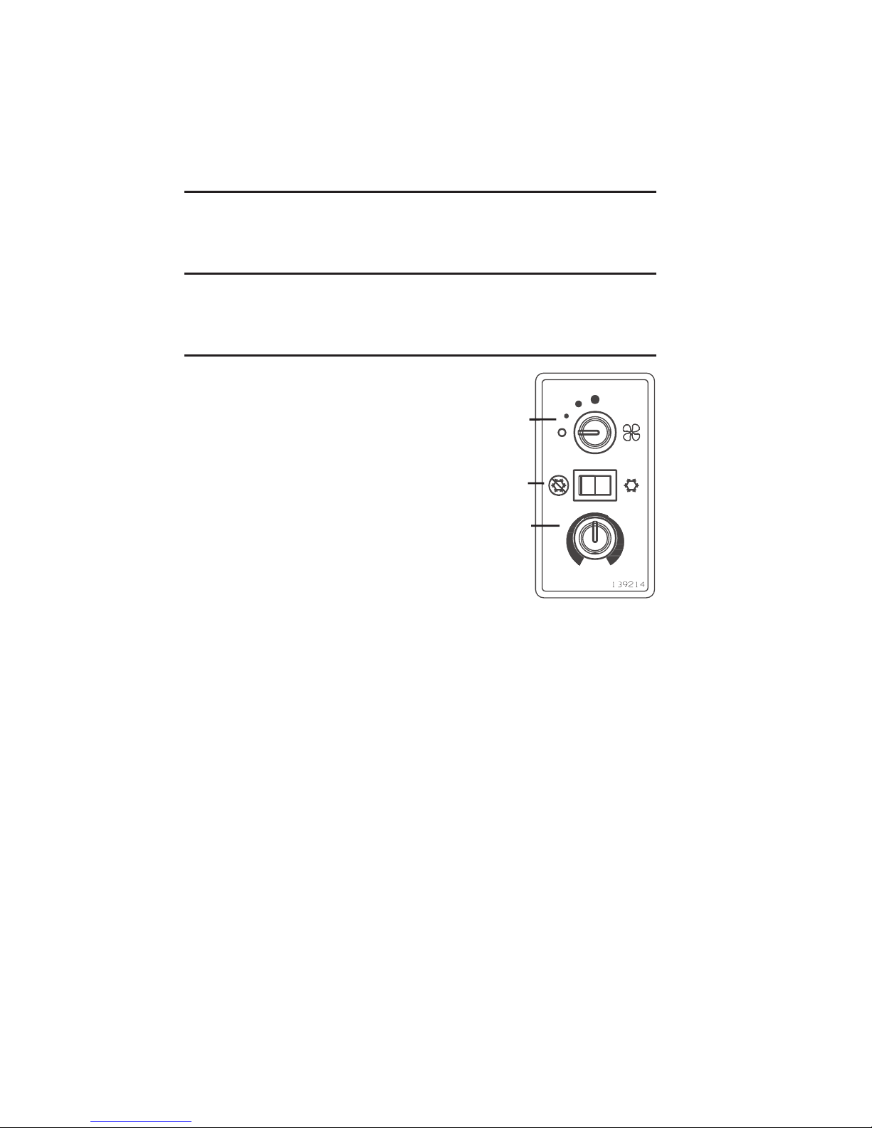
Heater and Air Conditioner (Optional)
Loaders with the combined heater/air conditioner
have three controls on the left instrument panel:
fan speed, airconditioner on/off and temperature.
1
1. Fan Speed: Controls the rate at which air
exits the vents
2. Air Conditioner On/Off: Turns the air
conditioner unit
ON and OFF
3. Temperature: Controls the temperature of
the air exiting the vents
Hint: The operator will feelcooler withjust the two
front vents opened and aimed at the upper body.
2
3
Fig. 6: Heater/
Air Conditioner Controls
19 908274/BP1202

Speed Control
A right-hand controlled throttle lever is provided
on all models for adjusting the engine speed.
Move the control forward to increase the engine
speed and rearwardto decrease the engine speed.
T-Bar and Dual Hand Controls Only: A
right-foot operated accelerator pedal is provided
to control the engine RPM. The pedal linkage is
spring-loaded to return to the adjusted
hand-operated throttle setting.
Fig. 8: Foot Pedal (T-Bar & Dual Hand)
Fig. 7: Throttle Lever
Two-Speed Transmission (optional)
Loaders with two-speed transmissions have a
YELLOW button on the left
control handle for shifting between High (H) and Low (L). Shifting to High
allows the operator to exceed the standard 8 mph (13 km/h) upto a maximum
speed of 14 mph (22.5 km/h).
Note: Loaders sold to European Union nations can exceed the standard speed
up to a maximum speed of 12.4 mph (20 km/h).
Hydraglide™ Ride Control System (optional)
Loaders with the optional ride control feature have a
BLUE button on the right
control handle for shifting between normal mode and ride control mode. The
ride control system provides a smoother ride over uneven surfaces. Press the
button once to activate and again to deactivate. The ride control system is
automatically deactivated when the machine shuts down.
Note: The lift arm will drop slightly when ride control is activated.
908274/BP1202 20
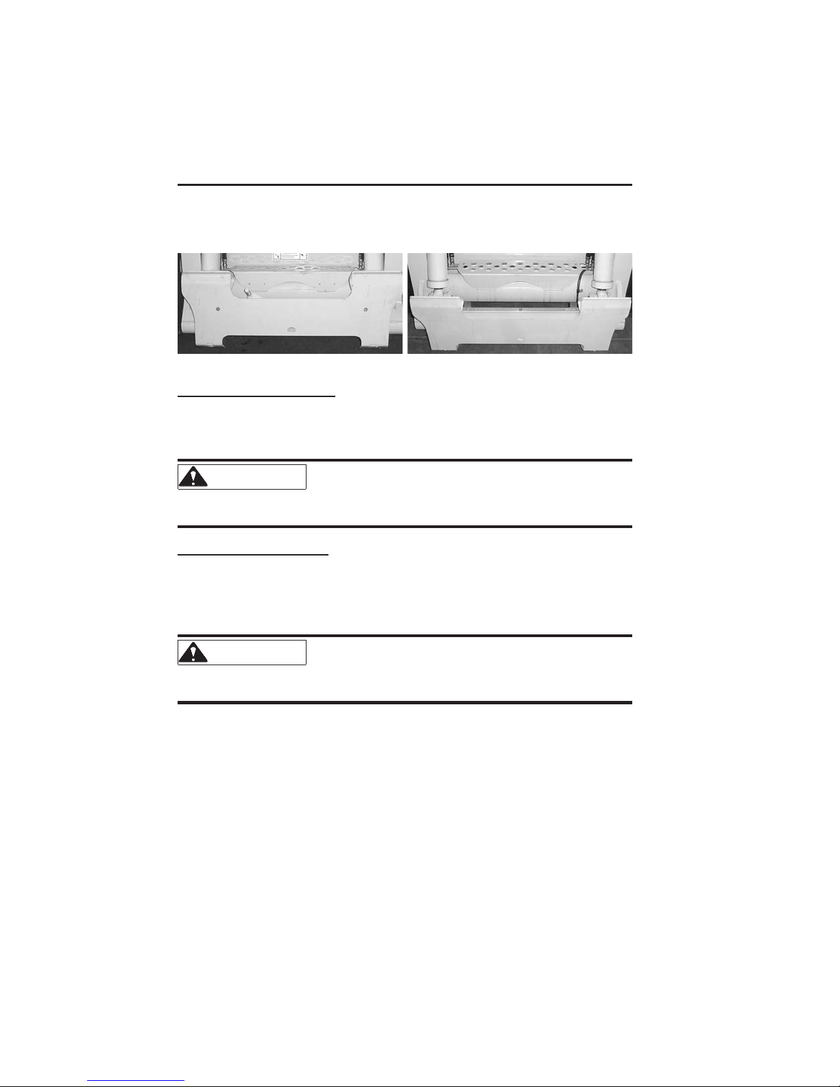
Attachment Mounting
Your Gehl loader may be equipped with either a manual All-Tach™
attaching mechanism (hitch) or power All-Tach™ hitch for mounting a
bucket or other attachment.
Fig. 9: Manual All-Tach Hitch
Fig. 10: Power All-Tach Hitch
Manual All-Tach Hitch
A manual latchlever engages the latch pins. Rotate the lever all theway to the
left to engage the latch pins. Rotate the lever all the way to the right to
disengage the latch pins. Refer to page 37 for more information.
WARNING
To prevent unexpected attachment release
from the hitch, be sure to secure the latch pins by rotating the lever
all the way to the left.
Power All-Tach Hitch
A switch on the left control panel activates the latch pins. Flags on the pins
indicated their position; the pin flags will move towards the outside of the
hitch when engaging the pins and towards the inside of the hitch when
disengaging the pins. Refer to page 37 for more information.
WARNING
To prevent unexpected attachment release
from the hitch, be sure the latch pins are secure by verifying that the
pin flags havemoved as faras possibleto theoutside ofthe hitch.
21 908274/BP1202
Instrument Panel
The instrument panel contains the following
switches and indicators. Symbols on the panel
represent various functions and conditions, and are
visible only when indicator lamps are on.
Left Panel
Note: Items 1 through 3 are indicator lights which
display the following:
1. Two-Speed High (optional) – Lights when high
speed is engaged.
2. Parking Brake – Lights when the parking brake
is applied.
3. Ride Control System (optional) – Lights when
the ride control system is activated.
4. Parking Brake Switch– Used tomanually apply
the parking brake.
5. Fan (optional) – Used to manually control the
fan for the air conditioner or heater.
6. Accessory Plug (optional) – A 12 VDC power
outlet.
7. Power All-Tach Hitch (optional) – Used to
operate the power All-Tach hitch.
1
2
3
7
5
6
Fig. 11: Left Panel
908274/BP1202 22
4

Right Panel
Note: Items 1 through 8 are indicator lights which
display the following:
1. Air Filter Restriction (optional) -Lights if
the air filter becomes restricted, warning the
operator to stop the engine. Inspect the air
cleaner filters and replace if necessary. During
normal operation, thisindicator should be
2. Engine Coolant Temperature – Lights if the
OFF.
9
engine coolant gets too hot, warning the
operator to stop the engine. Allow the engine
to cool, determine the cause for the high
10
temperature and correct the problem before
restarting the engine. During normal
operation, this indicator should be
OFF.
11
3. Hydraulic Oil Filter Restriction– Lights if
the hydraulic return filter becomes restricted,
warning the operator to stop the engine. Allow
the engine tocool then change the oiland filter.
1
5
During normal operation, this indicator should
be
OFF.
4. Hydraulic Oil Temperature – Lights if the
hydraulic oil becomes too hot, warning the
2
3
4
6
7
8
operator to stop engine. Allow the hydraulic
system to cool and determine the cause of the
high temperature. During normal operation,
this indicator should be
OFF.
12
5. Fasten Seatbelt – A momentary visual (and
audible) indicator to remind the operator to
fasten the seatbelt.
6. Engine Oil Pressure – Lights if the engine oil
13
pressure drops toolow, warning theoperator to
immediately stop theengine and determine the
cause for the pressure drop. During normal
operation, this indicator should be
OFF.
14
7. Battery – Lights if the charging voltage is too
high or too low. During normal operation, this
indicator should be
OFF.
8. Preheat Indicator Lamp – Lights when the
preheat is active. During normal operation,
this indicator should be
23 908274/BP1202
OFF.
Fig. 12: Right Panel

9. Hourmeter – Indicates the total operating hours of the loader.
10. Fuel Level Gauge – Indicates the amount of fuel in the tank.
11. Engine Coolant Temperature Gauge – Indicates the engine coolant
temperature.
12. Light Switch – Controls all the lights (standard and optional) on the
loader. Symbols denote the four positions of the light switch. In a
clockwise direction these are: Off, Flashers (Hazards), Work Lights with
Flashers, and Tail Lights. For thelights to function,the keyswitch must be
in the
RUN position.
13. Keyswitch – In a clockwise rotation, these positions are:
Off Position – With the key vertical (
OFF) in the keyswitch, power from
the battery is disconnected from the controls and instrument panel
electrical circuits. This is the only position the key can be inserted or
removed from the keyswitch.
On or Run Position – With the key turned one position clockwise (
from the vertical (
OFF) position, power from the battery is supplied to all
RUN)
control and instrument panel electrical circuits.
Start Position – With the key turned fully clockwise (
START) and held in
position, the electric starter energizes, startingthe engine. Releasethe key
after the engine starts (it returns to the
RUN position by itself).
Note: The engine cannot be started unless the operator sits in the seat and the
restraint bar is lowered.
14. Circuit Breakers – Four circuit breakers on the instrument panel protect
the loader’s electrical circuits.
Important: Do not attempt to defeat the circuit protection by jumping
across a circuit breaker or by using a higher amperage circuit breaker.
908274/BP1202 24
 Loading...