


MANUALEQUIPOSPESADOS.COM
SL3640, SL3840
and SL4240
Skid-Steer
Loaders
Form No.
917170
Revision A
01/06
®
Service Manual
MANUALEQUIPOSPESADOS.COM
INTRODUCTION
With correct maintenance and proper use, Gehl skid-steer loaders will give years of dependable service. This service manual is intended to be a guide in the assembly and disassembly, installation and removal, adjustment and testing, troubleshooting and replacement of components that together make up the Gehl SL3640/3840/4240 family of skid-steer loaders.
In many of the procedures found within, the installation steps are the exact opposite of the removal steps and vice versa, and therefore, the opposite procedure is not written. Instead, a note to reverse the procedure will be stated. This reduces redundancy and excessive pages in the manual. In cases though, where the assembly and disassembly or removal and installation procedures differ and additional steps or safety concerns are paramount, the entire reverse procedure will be written out to include the new information.
The Table of Contents and Index can be used to make the procedure you need to find an easier process. Also, there are black tabs extending off the pages highlighting the chapters for those who prefer to thumb through the manual. Many schematics, photographs, and line art drawings are used to help perform the necessary repairs, tests, or adjustments that the SL3640/3840/4240 skid-steer loaders need to keep them in good running condition.
If you have any additional questions, please contact your authorized Gehl dealer or call the Gehl Service Department for assistance.
Gehl is a registered trademark of the Gehl Company.

MANUALEQUIPOSPESADOS.COM |
TABLE OF CONTENTS |
SL3640/3840/4240 |
|
TABLE OF CONTENTS |
Specifications |
Page 1-1 |
Specifications · · · · · · · · · · · · · · · · · · · · · · · · · · · · · · · · · · · · · · · · · · · · · · · · · · · · · · · · · · · · · · · · · · · · · · 1-1 Tire Options · · · · · · · · · · · · · · · · · · · · · · · · · · · · · · · · · · · · · · · · · · · · · · · · · · · · · · · · · · · · · · · · · · · · · · · 1-1 Buckets and Capacities · · · · · · · · · · · · · · · · · · · · · · · · · · · · · · · · · · · · · · · · · · · · · · · · · · · · · · · · · · · · · · 1-1 General Specifications · · · · · · · · · · · · · · · · · · · · · · · · · · · · · · · · · · · · · · · · · · · · · · · · · · · · · · · · · · · · · · · 1-2
Safety Page 2-1
General Information · · · · · · · · · · · · · · · · · · · · · · · · · · · · · · · · · · · · · · · · · · · · · · · · · · · · · · · · · · · · · · · · · 2-1 Signal Words · · · · · · · · · · · · · · · · · · · · · · · · · · · · · · · · · · · · · · · · · · · · · · · · · · · · · · · · · · · · · · · · · · · · · · 2-1 Additional Safety Reminders · · · · · · · · · · · · · · · · · · · · · · · · · · · · · · · · · · · · · · · · · · · · · · · · · · · · · · · · · · 2-1 Mandatory Safety Shutdown Procedure · · · · · · · · · · · · · · · · · · · · · · · · · · · · · · · · · · · · · · · · · · · · · · · · · 2-2 Liftarm Support Device · · · · · · · · · · · · · · · · · · · · · · · · · · · · · · · · · · · · · · · · · · · · · · · · · · · · · · · · · · · · · · 2-3 Liftarm Support Device Engagement · · · · · · · · · · · · · · · · · · · · · · · · · · · · · · · · · · · · · · · · · · · · · · · · · · · 2-3 Liftarm Support Device Disengagement · · · · · · · · · · · · · · · · · · · · · · · · · · · · · · · · · · · · · · · · · · · · · · · · · 2-4 Rollover Protective Structure (ROPS) - Raising · · · · · · · · · · · · · · · · · · · · · · · · · · · · · · · · · · · · · · · · · · · 2-4 Rollover Protective Structure (ROPS) - Lowering · · · · · · · · · · · · · · · · · · · · · · · · · · · · · · · · · · · · · · · · · 2-5 Relieving Hydraulic Pressure· · · · · · · · · · · · · · · · · · · · · · · · · · · · · · · · · · · · · · · · · · · · · · · · · · · · · · · · · · 2-6 Skid-Steer Loader Raising Procedure · · · · · · · · · · · · · · · · · · · · · · · · · · · · · · · · · · · · · · · · · · · · · · · · · · · 2-6 Skid Loader Lowering Procedure · · · · · · · · · · · · · · · · · · · · · · · · · · · · · · · · · · · · · · · · · · · · · · · · · · · · · · 2-7
Lubrication Page 3-1
General Information · · · · · · · · · · · · · · · · · · · · · · · · · · · · · · · · · · · · · · · · · · · · · · · · · · · · · · · · · · · · · · · · · 3-1 Hydraulic Oil Reservoir · · · · · · · · · · · · · · · · · · · · · · · · · · · · · · · · · · · · · · · · · · · · · · · · · · · · · · · · · · · · · · 3-1 Crankcase Oil · · · · · · · · · · · · · · · · · · · · · · · · · · · · · · · · · · · · · · · · · · · · · · · · · · · · · · · · · · · · · · · · · · · · · · 3-2 Hydraulic Oil Tank Drain Procedure · · · · · · · · · · · · · · · · · · · · · · · · · · · · · · · · · · · · · · · · · · · · · · · · · · · · 3-2 Chaincases · · · · · · · · · · · · · · · · · · · · · · · · · · · · · · · · · · · · · · · · · · · · · · · · · · · · · · · · · · · · · · · · · · · · · · · · 3-3 Chaincase Oil Change Procedure· · · · · · · · · · · · · · · · · · · · · · · · · · · · · · · · · · · · · · · · · · · · · · · · · · · · · · · 3-3 Grease Fitting Locations · · · · · · · · · · · · · · · · · · · · · · · · · · · · · · · · · · · · · · · · · · · · · · · · · · · · · · · · · · · · · 3-3 Cooling System Drain Procedure· · · · · · · · · · · · · · · · · · · · · · · · · · · · · · · · · · · · · · · · · · · · · · · · · · · · · · · 3-4
PRINTED IN USA |
i |
917170/AP0106 |
MANUALEQUIPOSPESADOS.COM |
SL3640/3840/4240 |
||
|
TABLE OF CONTENTS |
||
|
Mainframe |
Page 4-1 |
|
|
|
|
|
Introduction · · · · · · · · · · · · · · · · · · · · · · · · · · · · · · · · · · · · · · · · · · · · · · · · · · · · · · · · · · · · · · · · · · · · · · · 4-1 Engine Access Cover Removal and Installation · · · · · · · · · · · · · · · · · · · · · · · · · · · · · · · · · · · · · · · · · · · 4-2 Rollover Protective Structure (ROPS) Removal and Installation · · · · · · · · · · · · · · · · · · · · · · · · · · · · · · 4-2 Seat Removal and Installation · · · · · · · · · · · · · · · · · · · · · · · · · · · · · · · · · · · · · · · · · · · · · · · · · · · · · · · · · 4-4 Seat Slide Replacement · · · · · · · · · · · · · · · · · · · · · · · · · · · · · · · · · · · · · · · · · · · · · · · · · · · · · · · · · · · · · · 4-4 Rollover Protective Structure (ROPS) Rear Window Removal and Installation · · · · · · · · · · · · · · · · · · 4-5 Restraint Bar Removal and Installation · · · · · · · · · · · · · · · · · · · · · · · · · · · · · · · · · · · · · · · · · · · · · · · · · · 4-7 All-Tach™ Bracket Removal and Installation· · · · · · · · · · · · · · · · · · · · · · · · · · · · · · · · · · · · · · · · · · · · · 4-9 Liftarm Removal and Installation · · · · · · · · · · · · · · · · · · · · · · · · · · · · · · · · · · · · · · · · · · · · · · · · · · · · · · 4-10 Liftarm Bushing Replacement · · · · · · · · · · · · · · · · · · · · · · · · · · · · · · · · · · · · · · · · · · · · · · · · · · · · · · · · · 4-13 Liftarm Stop Installation and Adjustment · · · · · · · · · · · · · · · · · · · · · · · · · · · · · · · · · · · · · · · · · · · · · · · · 4-14 Floor Cover and Kick Plate Removal and Installation · · · · · · · · · · · · · · · · · · · · · · · · · · · · · · · · · · · · · · 4-16 Fuel Level Sender Removal and Installation · · · · · · · · · · · · · · · · · · · · · · · · · · · · · · · · · · · · · · · · · · · · · · 4-19 Rear Grille Removal and Installation· · · · · · · · · · · · · · · · · · · · · · · · · · · · · · · · · · · · · · · · · · · · · · · · · · · · 4-20
Wheel Drives |
Page 5-1 |
|
|
Introduction · · · · · · · · · · · · · · · · · · · · · · · · · · · · · · · · · · · · · · · · · · · · · · · · · · · · · · · · · · · · · · · · · · · · · · · 5-1 Drive Chain Adjustment · · · · · · · · · · · · · · · · · · · · · · · · · · · · · · · · · · · · · · · · · · · · · · · · · · · · · · · · · · · · · 5-2 Drive Chain Removal and Installation· · · · · · · · · · · · · · · · · · · · · · · · · · · · · · · · · · · · · · · · · · · · · · · · · · · 5-3 Axle Removal and Installation· · · · · · · · · · · · · · · · · · · · · · · · · · · · · · · · · · · · · · · · · · · · · · · · · · · · · · · · · 5-4
Controls |
Page 6-1 |
|
|
Introduction · · · · · · · · · · · · · · · · · · · · · · · · · · · · · · · · · · · · · · · · · · · · · · · · · · · · · · · · · · · · · · · · · · · · · · · 6-1 Control Handle Removal and Installation · · · · · · · · · · · · · · · · · · · · · · · · · · · · · · · · · · · · · · · · · · · · · · · · 6-6 Control Handle Position and Tracking Adjustment· · · · · · · · · · · · · · · · · · · · · · · · · · · · · · · · · · · · · · · · · 6-7 Dual Control Weldment Removal and Installation - T-Bar Controls · · · · · · · · · · · · · · · · · · · · · · · · · · · 6-9 Neutral Centering Device and Pump Arm Removal and Installation · · · · · · · · · · · · · · · · · · · · · · · · · · · 6-10 Neutral Centering Device Adjustment· · · · · · · · · · · · · · · · · · · · · · · · · · · · · · · · · · · · · · · · · · · · · · · · · · · 6-11 Lift/Tilt Control Removal and Installation · · · · · · · · · · · · · · · · · · · · · · · · · · · · · · · · · · · · · · · · · · · · · · · 6-12 Lift/Tilt Control Adjustment · · · · · · · · · · · · · · · · · · · · · · · · · · · · · · · · · · · · · · · · · · · · · · · · · · · · · · · · · · 6-13 Auxiliary Hydraulics Removal and Installation · · · · · · · · · · · · · · · · · · · · · · · · · · · · · · · · · · · · · · · · · · · 6-14 Auxiliary Hydraulics Adjustment · · · · · · · · · · · · · · · · · · · · · · · · · · · · · · · · · · · · · · · · · · · · · · · · · · · · · · 6-15 Hand Throttle, Hand Throttle Cable and Throttle Rod Removal and Installation · · · · · · · · · · · · · · · · · 6-16 Foot Throttle and Foot Throttle Cable Removal and Installation - T-Bar Controls · · · · · · · · · · · · · · · · 6-18 Hand Throttle Adjustment · · · · · · · · · · · · · · · · · · · · · · · · · · · · · · · · · · · · · · · · · · · · · · · · · · · · · · · · · · · · 6-19 Hand Throttle Tension Adjustment · · · · · · · · · · · · · · · · · · · · · · · · · · · · · · · · · · · · · · · · · · · · · · · · · · · · · 6-20 Foot Throttle Adjustment - T-Bar Controls · · · · · · · · · · · · · · · · · · · · · · · · · · · · · · · · · · · · · · · · · · · · · · · 6-21
917170/AP0106 |
ii |
PRINTED IN USA |
MANUALEQUIPOSPESADOS.COM |
TABLE OF CONTENTS |
||
|
SL3640/3840/4240 |
||
|
|
Hydrostatic System |
Page 7-1 |
|
|
|
|
Introduction · · · · · · · · · · · · · · · · · · · · · · · · · · · · · · · · · · · · · · · · · · · · · · · · · · · · · · · · · · · · · · · · · · · · · · · 7-1 Troubleshooting Guide· · · · · · · · · · · · · · · · · · · · · · · · · · · · · · · · · · · · · · · · · · · · · · · · · · · · · · · · · · · · · · · 7-3 Charge Pressure Test and Adjustment · · · · · · · · · · · · · · · · · · · · · · · · · · · · · · · · · · · · · · · · · · · · · · · · · · · 7-7 Hydrostatic Pump Relief Valves · · · · · · · · · · · · · · · · · · · · · · · · · · · · · · · · · · · · · · · · · · · · · · · · · · · · · · · 7-8 Drive Motor Hot Oil Shuttle Valve · · · · · · · · · · · · · · · · · · · · · · · · · · · · · · · · · · · · · · · · · · · · · · · · · · · · · 7-8 Hydrostatic Pump Removal and Installation · · · · · · · · · · · · · · · · · · · · · · · · · · · · · · · · · · · · · · · · · · · · · · 7-9 Hydrostatic Pump Flexible Drive Plate Removal and Installation · · · · · · · · · · · · · · · · · · · · · · · · · · · · · 7-11 Drive Motor Removal and Installation · · · · · · · · · · · · · · · · · · · · · · · · · · · · · · · · · · · · · · · · · · · · · · · · · · 7-12
Hydraulic System |
Page 8-1 |
|
|
Introduction · · · · · · · · · · · · · · · · · · · · · · · · · · · · · · · · · · · · · · · · · · · · · · · · · · · · · · · · · · · · · · · · · · · · · · · 8-1 Troubleshooting Guide· · · · · · · · · · · · · · · · · · · · · · · · · · · · · · · · · · · · · · · · · · · · · · · · · · · · · · · · · · · · · · · 8-3 System Pressure Test - Control Valve · · · · · · · · · · · · · · · · · · · · · · · · · · · · · · · · · · · · · · · · · · · · · · · · · · · 8-7 Tilt Cylinder Test · · · · · · · · · · · · · · · · · · · · · · · · · · · · · · · · · · · · · · · · · · · · · · · · · · · · · · · · · · · · · · · · · · · 8-9 Self-Leveling Valve Test · · · · · · · · · · · · · · · · · · · · · · · · · · · · · · · · · · · · · · · · · · · · · · · · · · · · · · · · · · · · · 8-11 Self-Leveling Valve Adjustment · · · · · · · · · · · · · · · · · · · · · · · · · · · · · · · · · · · · · · · · · · · · · · · · · · · · · · · 8-12 Lift Cylinder Test · · · · · · · · · · · · · · · · · · · · · · · · · · · · · · · · · · · · · · · · · · · · · · · · · · · · · · · · · · · · · · · · · · · 8-13 Solenoid Valve Test · · · · · · · · · · · · · · · · · · · · · · · · · · · · · · · · · · · · · · · · · · · · · · · · · · · · · · · · · · · · · · · · · 8-14 Hydraulic Oil Filter Element Replacement · · · · · · · · · · · · · · · · · · · · · · · · · · · · · · · · · · · · · · · · · · · · · · · 8-16 Tilt Cylinder Removal and Installation · · · · · · · · · · · · · · · · · · · · · · · · · · · · · · · · · · · · · · · · · · · · · · · · · · 8-19 Lift Cylinder Removal and Installation · · · · · · · · · · · · · · · · · · · · · · · · · · · · · · · · · · · · · · · · · · · · · · · · · · 8-21 Lift and Tilt Cylinder Disassembly and Assembly · · · · · · · · · · · · · · · · · · · · · · · · · · · · · · · · · · · · · · · · · 8-23 Gear Pump Removal and Installation · · · · · · · · · · · · · · · · · · · · · · · · · · · · · · · · · · · · · · · · · · · · · · · · · · · 8-24 Self-Leveling Valve Removal and Installation · · · · · · · · · · · · · · · · · · · · · · · · · · · · · · · · · · · · · · · · · · · · 8-26 Safety Lock Valves - Removal and Installation · · · · · · · · · · · · · · · · · · · · · · · · · · · · · · · · · · · · · · · · · · · 8-27 Lift, Tilt and Brake Safety Lock Valves - Disassembly and Assembly · · · · · · · · · · · · · · · · · · · · · · · · · 8-29 Control Valve Removal and Installation · · · · · · · · · · · · · · · · · · · · · · · · · · · · · · · · · · · · · · · · · · · · · · · · · 8-30 Hydraulic/Hydrostatic System Schematic · · · · · · · · · · · · · · · · · · · · · · · · · · · · · · · · · · · · · · · · · · · · · · · · 8-32
All-Tach is a trademark of the Gehl Company.
PRINTED IN USA |
iii |
917170/AP0106 |

MANUALEQUIPOSPESADOS.COM |
SL3640/3840/4240 |
||
|
TABLE OF CONTENTS |
||
|
Electrical System |
Page 9-1 |
|
|
|
|
|
Description of Operation · · · · · · · · · · · · · · · · · · · · · · · · · · · · · · · · · · · · · · · · · · · · · · · · · · · · · · · · · · · · · 9-1 Troubleshooting Guide· · · · · · · · · · · · · · · · · · · · · · · · · · · · · · · · · · · · · · · · · · · · · · · · · · · · · · · · · · · · · · · 9-4 Relay Test and Operation· · · · · · · · · · · · · · · · · · · · · · · · · · · · · · · · · · · · · · · · · · · · · · · · · · · · · · · · · · · · · 9-6 Electrical Circuits· · · · · · · · · · · · · · · · · · · · · · · · · · · · · · · · · · · · · · · · · · · · · · · · · · · · · · · · · · · · · · · · · · · 9-8 Seat Switch Removal and Installation · · · · · · · · · · · · · · · · · · · · · · · · · · · · · · · · · · · · · · · · · · · · · · · · · · · 9-15 Restraint Bar Switch Removal and Installation · · · · · · · · · · · · · · · · · · · · · · · · · · · · · · · · · · · · · · · · · · · · 9-16 Front and Rear Work Light Bulb Replacement · · · · · · · · · · · · · · · · · · · · · · · · · · · · · · · · · · · · · · · · · · · · 9-17 Electrical System Schematic · · · · · · · · · · · · · · · · · · · · · · · · · · · · · · · · · · · · · · · · · · · · · · · · · · · · · · · · · · 9-18
Engine |
Page 10-1 |
|
|
|
|
Introduction · · · · · · · · · · · · · · · · · · · · · · · · · · · · · · · · · · · · · · · · · · · · · · · · · · · · · · · · · · · · · · · · · · · · · · · 10-1 Troubleshooting Guide· · · · · · · · · · · · · · · · · · · · · · · · · · · · · · · · · · · · · · · · · · · · · · · · · · · · · · · · · · · · · · · 10-2 Engine Oil Filter Element Removal and Installation· · · · · · · · · · · · · · · · · · · · · · · · · · · · · · · · · · · · · · · · 10-4 Air Cleaner Assembly Removal and Installation· · · · · · · · · · · · · · · · · · · · · · · · · · · · · · · · · · · · · · · · · · · 10-7 Air Filter Element Removal and Installation · · · · · · · · · · · · · · · · · · · · · · · · · · · · · · · · · · · · · · · · · · · · · · 10-7 Fuel Filter Removal and Installation · · · · · · · · · · · · · · · · · · · · · · · · · · · · · · · · · · · · · · · · · · · · · · · · · · · · 10-8 Water Separator Element Removal and Installation · · · · · · · · · · · · · · · · · · · · · · · · · · · · · · · · · · · · · · · · 10-8 Electric Fuel Pump Removal and Installation · · · · · · · · · · · · · · · · · · · · · · · · · · · · · · · · · · · · · · · · · · · · · 10-9 Priming Diesel Fuel System· · · · · · · · · · · · · · · · · · · · · · · · · · · · · · · · · · · · · · · · · · · · · · · · · · · · · · · · · · · 10-9 Battery Removal and Installation· · · · · · · · · · · · · · · · · · · · · · · · · · · · · · · · · · · · · · · · · · · · · · · · · · · · · · · 10-10 Starter Removal and Installation · · · · · · · · · · · · · · · · · · · · · · · · · · · · · · · · · · · · · · · · · · · · · · · · · · · · · · · 10-11 Exhaust Assembly Removal and Installation · · · · · · · · · · · · · · · · · · · · · · · · · · · · · · · · · · · · · · · · · · · · · 10-11 Fan Belt Adjustment · · · · · · · · · · · · · · · · · · · · · · · · · · · · · · · · · · · · · · · · · · · · · · · · · · · · · · · · · · · · · · · · 10-12 Radiator/Cooler Removal and Installation· · · · · · · · · · · · · · · · · · · · · · · · · · · · · · · · · · · · · · · · · · · · · · · · 10-15 Fan Shroud Removal and Installation - 4240 Models · · · · · · · · · · · · · · · · · · · · · · · · · · · · · · · · · · · · · · · 10-16 Fuel Tank Removal and Installation · · · · · · · · · · · · · · · · · · · · · · · · · · · · · · · · · · · · · · · · · · · · · · · · · · · · 10-17 Engine Removal and Installation · · · · · · · · · · · · · · · · · · · · · · · · · · · · · · · · · · · · · · · · · · · · · · · · · · · · · · · 10-19
Index
917170/AP0106 |
iv |
PRINTED IN USA |

MANUALEQUIPOSPESADOS.COM |
SPECIFICATIONS |
SL3640/3840/4240 |
SPECIFICATIONS
|
SL3640/3840 |
SL4240 |
Engine Make |
Yanmar |
Yanmar |
Model |
3TNV88-XMS2 |
4TNV88-XMS2 |
Fuel |
Diesel |
Diesel |
Displacement |
100 CID (1,64 L) |
133 CID (2,19 L) |
Horsepower - Net (SAE) |
35 hp (26 kW) @ 2600 rpm |
46 hp (34 kW) @ 2600 rpm |
Torque - Maximum |
80 ft.-lbs. (108,5 N•m) @ 1200 rpm |
103 ft.-lbs. (139,7 N•m) @ 1200 rpm |
Rated Operating Load (SAE)* |
1050 lbs. (476 kg) |
1350 lbs. (612 kg) |
Operating Weight |
4000 lbs. (1814 kg) |
4600 lbs. (2087 kg) |
Shipping Weight |
3515 lbs. (1594 kg) |
4065 lbs. (1844 kg) |
Engine Oil |
7.6 US qts. (7,2 L) |
9.1 US qts. (8,6 L) |
Fuel Tank |
10.3 US gal. (39 L) |
12.4 US gal. (47 L) |
Standard Flow Rate |
14.5 gpm (55 L/min) |
16.5 gpm (62 L/min) |
Travel Speed (max) |
6.4 mph (10,3 km/h) |
6.8 mph (10,9 km/h) |
Specifications below apply to all 3640, 3840 and 4240 models
Capacities
Chaincases (each) |
|
8.0 US qts. (7,6 L) |
Hydraulic Reservoir |
|
8.0 US gal. (30 L) |
|
Electrical |
|
Battery |
|
12-volt DC, 675 CCA |
Starter |
|
12-volt DC (2.0 kW) |
Alternator |
|
40 A |
|
Hydraulic System |
|
Main Hydraulic System Pressure |
|
2750 psi (190 bar) |
|
|
|
|
Tire Options |
|
7 x 15 |
|
SS Narrow |
8.5 x 15 - 8 ply |
|
Heavy-Duty Flotation |
10.50 x 15 - 8 ply |
|
Heavy-Duty Flotation |
10 x 16.5 - 6 ply |
|
Standard Flotation |
10 x 16.5 - 8 ply |
|
Heavy-Duty Flotation/Foam-Filled |
10 x 16.5 - 10 ply |
|
Severe-Duty/Severe-Duty Foam-Filled |
6.5 x 16 |
|
Solid Rubber |
Buckets and Capacities
Width |
Description |
|
Capacity (Heaped) |
|
48 inches (1219 mm) |
Dirt/Construction |
9.75 cubic feet |
|
0,27 cubic meters |
48 inches (1219 mm) |
Utility |
11.9 cubic feet |
|
0,34 cubic meters |
54 inches (1372 mm) |
Dirt/Construction |
9.5 cubic feet |
|
0,27 cubic meters |
54 inches (1372 mm) |
Utility |
13.5 cubic feet |
|
0,38 cubic meters |
55 inches (1397 mm) |
Dirt/Construction |
10.5 cubic feet |
|
0,30 cubic meters |
60 inches (1524 mm) |
Utility |
15.2 cubic feet |
|
0,43 cubic meters |
61 inches (1550 mm) |
Dirt/Construction |
11.7 cubic feet |
|
0,33 cubic meters |
61.5 inches (1562 mm) |
Low Profile |
12.6 cubic feet |
|
0,36 cubic meters |
61.5 inches (1562 mm) |
Earth & Foundry |
13.0 cubic feet |
|
0,37 cubic meters |
61.5 inches (1562 mm) |
Construction |
13.0 cubic feet |
|
0,37 cubic meters |
3640/3840 SAE Rated Operating Load: Operating load rated with a 54" (1372 mm) dirt/construction bucket in accordance with SAE J818. 4240 SAE Rated Operating Load: Operating load rated with a 60" (1524 mm) dirt/construction bucket in accordance with SAE J818.
SPECIFICATIONS
PRINTED IN USA |
1-1 |
917170/AP0106 |
MANUALEQUIPOSPESADOS.COM |
SL3640/3840/4240 |
SPECIFICATIONS |
|
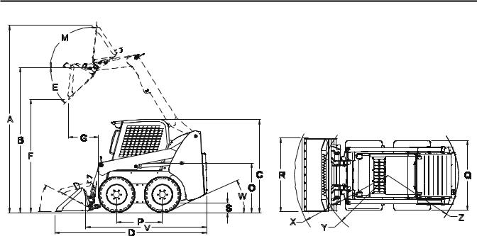
General Specifications |
SL3640/3840 (1) |
SL4240 (2) |
||||
|
inches |
|
millimeters |
inches |
|
millimeters |
|
|
|
|
|
||||
A |
Overall operation height - fully raised |
139.6 |
|
3546 |
141.1 |
|
3584 |
B |
Height to hinge pin - fully raised |
108.1 |
|
2746 |
110 |
|
2794 |
C |
Overall height - top of ROPS |
70.3 |
|
1786 |
71.9 |
|
1826 |
D |
Overall length (w/54” dirt/construction bucket down) |
114.5 |
|
2908 |
|
|
|
|
Overall length (w/60” dirt/construction bucket down) |
|
|
|
116.2 |
|
2952 |
E |
Dump angle @ full height |
|
42° |
|
42° |
||
F |
Dump height (w/54” dirt/construction bucket) |
84.5 |
|
2146 |
|
|
|
|
Dump height (w/60” dirt/construction bucket) |
|
|
|
86.5 |
|
2197 |
G |
Dump reach - w/54” dirt/construction bucket (full height) |
22.8 |
|
578 |
|
|
|
|
Dump reach - w/60” dirt/construction bucket (full height) |
|
|
|
20.6 |
|
523 |
I |
Rollback at ground |
|
29° |
29° |
|
|
|
M |
Rollback at full height |
|
99° |
99° |
|
|
|
O |
Seat-to-ground height |
32.6 |
|
828 |
33.6 |
|
853 |
P |
Wheelbase |
34.5 |
|
876 |
36.7 |
|
932 |
Q |
Overall width - no bucket (w/27 x 8.5 x 15 tires) |
48.4/58.2 |
|
1229/1428 |
|
|
|
|
Overall width - no bucket (w/10 x 16.5 tires) |
|
|
|
52.5/58.4 |
|
1334/1483 |
R |
Overall bucket width - 54” dirt/construction bucket |
55.3 |
|
1403 |
|
|
|
|
Overall bucket width - 60” dirt/construction bucket |
|
|
|
60.6 |
|
1539 |
S |
Ground clearance to mainframe (between wheels) |
6 |
|
152 |
8.3 |
|
211 |
V |
Overall length (no bucket) |
88.9 |
|
2258 |
91.1 |
|
2314 |
W |
Departure angle |
|
26° |
29° |
|
|
|
X |
Clearance circle - front (w/54” dirt/construction bucket) |
69.4 |
|
1763 |
|
|
|
|
Clearance circle - front (w/60” utility bucket) |
|
|
|
69.2 |
|
1758 |
Y |
Clearance circle - front (no bucket) |
44.1 |
|
1120 |
43.4 |
|
1102 |
Z |
Clearance circle - rear |
54.1 |
|
1374 |
58.4 |
|
1484 |
(1)Dimensions with 27 x 8.50 x 15 HD tires and 54” bucket.
(2)Dimensions with 10.00 x 16.5 HD tires and 60” bucket.
917170/AP0106 |
1-2 |
PRINTED IN USA |
 Loading...